US10928362B2 - Nondestructive inspection using dual pulse-echo ultrasonics and method therefor - Google Patents
Nondestructive inspection using dual pulse-echo ultrasonics and method therefor Download PDFInfo
- Publication number
- US10928362B2 US10928362B2 US15/971,270 US201815971270A US10928362B2 US 10928362 B2 US10928362 B2 US 10928362B2 US 201815971270 A US201815971270 A US 201815971270A US 10928362 B2 US10928362 B2 US 10928362B2
- Authority
- US
- United States
- Prior art keywords
- model
- component
- pulse
- echo
- scan
- Prior art date
- Legal status (The legal status is an assumption and is not a legal conclusion. Google has not performed a legal analysis and makes no representation as to the accuracy of the status listed.)
- Active, expires
Links
Images


Classifications
-
- G—PHYSICS
- G01—MEASURING; TESTING
- G01N—INVESTIGATING OR ANALYSING MATERIALS BY DETERMINING THEIR CHEMICAL OR PHYSICAL PROPERTIES
- G01N29/00—Investigating or analysing materials by the use of ultrasonic, sonic or infrasonic waves; Visualisation of the interior of objects by transmitting ultrasonic or sonic waves through the object
- G01N29/04—Analysing solids
- G01N29/043—Analysing solids in the interior, e.g. by shear waves
-
- G—PHYSICS
- G01—MEASURING; TESTING
- G01N—INVESTIGATING OR ANALYSING MATERIALS BY DETERMINING THEIR CHEMICAL OR PHYSICAL PROPERTIES
- G01N29/00—Investigating or analysing materials by the use of ultrasonic, sonic or infrasonic waves; Visualisation of the interior of objects by transmitting ultrasonic or sonic waves through the object
- G01N29/22—Details, e.g. general constructional or apparatus details
- G01N29/26—Arrangements for orientation or scanning by relative movement of the head and the sensor
-
- G—PHYSICS
- G01—MEASURING; TESTING
- G01N—INVESTIGATING OR ANALYSING MATERIALS BY DETERMINING THEIR CHEMICAL OR PHYSICAL PROPERTIES
- G01N29/00—Investigating or analysing materials by the use of ultrasonic, sonic or infrasonic waves; Visualisation of the interior of objects by transmitting ultrasonic or sonic waves through the object
- G01N29/04—Analysing solids
- G01N29/06—Visualisation of the interior, e.g. acoustic microscopy
- G01N29/0654—Imaging
-
- G—PHYSICS
- G01—MEASURING; TESTING
- G01N—INVESTIGATING OR ANALYSING MATERIALS BY DETERMINING THEIR CHEMICAL OR PHYSICAL PROPERTIES
- G01N29/00—Investigating or analysing materials by the use of ultrasonic, sonic or infrasonic waves; Visualisation of the interior of objects by transmitting ultrasonic or sonic waves through the object
- G01N29/04—Analysing solids
- G01N29/11—Analysing solids by measuring attenuation of acoustic waves
-
- G—PHYSICS
- G01—MEASURING; TESTING
- G01N—INVESTIGATING OR ANALYSING MATERIALS BY DETERMINING THEIR CHEMICAL OR PHYSICAL PROPERTIES
- G01N29/00—Investigating or analysing materials by the use of ultrasonic, sonic or infrasonic waves; Visualisation of the interior of objects by transmitting ultrasonic or sonic waves through the object
- G01N29/22—Details, e.g. general constructional or apparatus details
- G01N29/225—Supports, positioning or alignment in moving situation
-
- G—PHYSICS
- G01—MEASURING; TESTING
- G01N—INVESTIGATING OR ANALYSING MATERIALS BY DETERMINING THEIR CHEMICAL OR PHYSICAL PROPERTIES
- G01N29/00—Investigating or analysing materials by the use of ultrasonic, sonic or infrasonic waves; Visualisation of the interior of objects by transmitting ultrasonic or sonic waves through the object
- G01N29/22—Details, e.g. general constructional or apparatus details
- G01N29/26—Arrangements for orientation or scanning by relative movement of the head and the sensor
- G01N29/265—Arrangements for orientation or scanning by relative movement of the head and the sensor by moving the sensor relative to a stationary material
-
- G—PHYSICS
- G01—MEASURING; TESTING
- G01N—INVESTIGATING OR ANALYSING MATERIALS BY DETERMINING THEIR CHEMICAL OR PHYSICAL PROPERTIES
- G01N29/00—Investigating or analysing materials by the use of ultrasonic, sonic or infrasonic waves; Visualisation of the interior of objects by transmitting ultrasonic or sonic waves through the object
- G01N29/44—Processing the detected response signal, e.g. electronic circuits specially adapted therefor
- G01N29/4409—Processing the detected response signal, e.g. electronic circuits specially adapted therefor by comparison
- G01N29/4418—Processing the detected response signal, e.g. electronic circuits specially adapted therefor by comparison with a model, e.g. best-fit, regression analysis
-
- G—PHYSICS
- G01—MEASURING; TESTING
- G01N—INVESTIGATING OR ANALYSING MATERIALS BY DETERMINING THEIR CHEMICAL OR PHYSICAL PROPERTIES
- G01N2291/00—Indexing codes associated with group G01N29/00
- G01N2291/02—Indexing codes associated with the analysed material
- G01N2291/023—Solids
- G01N2291/0231—Composite or layered materials
-
- G—PHYSICS
- G01—MEASURING; TESTING
- G01N—INVESTIGATING OR ANALYSING MATERIALS BY DETERMINING THEIR CHEMICAL OR PHYSICAL PROPERTIES
- G01N2291/00—Indexing codes associated with group G01N29/00
- G01N2291/02—Indexing codes associated with the analysed material
- G01N2291/028—Material parameters
- G01N2291/0289—Internal structure, e.g. defects, grain size, texture
-
- G—PHYSICS
- G01—MEASURING; TESTING
- G01N—INVESTIGATING OR ANALYSING MATERIALS BY DETERMINING THEIR CHEMICAL OR PHYSICAL PROPERTIES
- G01N2291/00—Indexing codes associated with group G01N29/00
- G01N2291/04—Wave modes and trajectories
- G01N2291/044—Internal reflections (echoes), e.g. on walls or defects
-
- G—PHYSICS
- G01—MEASURING; TESTING
- G01N—INVESTIGATING OR ANALYSING MATERIALS BY DETERMINING THEIR CHEMICAL OR PHYSICAL PROPERTIES
- G01N2291/00—Indexing codes associated with group G01N29/00
- G01N2291/04—Wave modes and trajectories
- G01N2291/048—Transmission, i.e. analysed material between transmitter and receiver
-
- G—PHYSICS
- G01—MEASURING; TESTING
- G01N—INVESTIGATING OR ANALYSING MATERIALS BY DETERMINING THEIR CHEMICAL OR PHYSICAL PROPERTIES
- G01N2291/00—Indexing codes associated with group G01N29/00
- G01N2291/04—Wave modes and trajectories
- G01N2291/051—Perpendicular incidence, perpendicular propagation
-
- G—PHYSICS
- G01—MEASURING; TESTING
- G01N—INVESTIGATING OR ANALYSING MATERIALS BY DETERMINING THEIR CHEMICAL OR PHYSICAL PROPERTIES
- G01N2291/00—Indexing codes associated with group G01N29/00
- G01N2291/10—Number of transducers
-
- G—PHYSICS
- G01—MEASURING; TESTING
- G01N—INVESTIGATING OR ANALYSING MATERIALS BY DETERMINING THEIR CHEMICAL OR PHYSICAL PROPERTIES
- G01N2291/00—Indexing codes associated with group G01N29/00
- G01N2291/26—Scanned objects
- G01N2291/269—Various geometry objects
- G01N2291/2694—Wings or other aircraft parts
Definitions
- the present disclosure relates to nondestructive component inspection and, more particularly, to a nondestructive ultrasonic damage detection system for prognostics and health management, preventative maintenance, and repair of engine components.
- Manufactured components may incur defects or imperfections during manufacturing or suffer wear and damage during operation. These components, therefore, are episodically or periodically inspected for defects and damage.
- One particular form of imperfection or damage consists of a “kissing bond” (also referred to as a zero-volume disbond) which is an interfacial or interstitial defect within a bond of a composite structure which shows no sign of separation at the interface.
- the defect is such that the opposing surfaces are substantially in contact with one another but are not bonded together. This may happen, for instance, when an adhesive begins to cure (“skins over”) before the parts are mated. An interstitial defect in the adhesive greatly decreases the strength of the bond.
- Ultrasonic pulse echo one-sided
- Ultrasonic through-transmission two-sided
- the detection of the local difference may be improved by differential signal processing, by computing a difference between an expected energy, typically based on prior experimentation or a physics-based model, and the received energy. In the case of a proper bond, the difference is effectively zero; in the case of a disbond, the difference is non-zero.
- the traditional through-transmission technique aligns a transmitter on one side of a component under inspection and receiver opposite the transmitter on the other side along a common axis orthogonal to the component. This technique effectively ignores the actual acoustic path through any internal structure of the component. In particular, when the internal structure is not orthogonal to the surface, the receiver may not be aimed at the emergence location of the transmitted sound energy.
- a method for nondestructive inspection of a component includes determining a first pulse-echo scan from a first side of a component; determining a second pulse-echo scan from a second side of the component; comparing the first pulse-echo scan to a first model from the first side of the component, the first model comprises a rigid internal structure of the component; comparing the second pulse-echo scan to a second model from the second side of the component, the second model comprises the rigid internal structure of the component; and classifying the component based on the comparing.
- a further aspect of the present disclosure includes guiding a first pulse echo ultrasonic transducer in accords with the first model and a second pulse echo ultrasonic transducer in accords with the second model.
- a further aspect of the present disclosure includes that the guiding comprises identifying a defect only within a predetermined area.
- a further aspect of the present disclosure includes determining a defect in response to at least one of a difference between the first through-transmission scan and a first gold model and a difference between the second through-transmission scan and a second gold model.
- a further aspect of the present disclosure includes that the guiding aligns the first pulse-echo ultrasonic transducer and the second pulse-echo ultrasonic transducer along a path of maximum energy transmission.
- a further aspect of the present disclosure includes that the guiding comprises defining a predetermined area adjacent the rigid internal structure of the component.
- a further aspect of the present disclosure includes that the defining the predetermined area is associated with a side of the component.
- a further aspect of the present disclosure includes that classifying the component comprises identifying a delamination area.
- a further aspect of the present disclosure includes at least one of a through-transmission scan from the first side of the component to the second side of the component using the first model; and a through-transmission scan from the second side of the component to the first side of the component using the second model.
- a method for nondestructive inspection of a component includes guiding a first pulse echo ultrasonic transducer in accords with a first model of a component and a second pulse echo ultrasonic transducer in accords with a second model of the component; determining a first pulse-echo scan from a first side of a component; determining a second pulse-echo scan from a second side of the component; and identifying a defect only from within a predetermined area of the component based on the first model and the second model.
- a further aspect of the present disclosure includes that the predetermined area is an area that includes a rigid internal structure.
- a further aspect of the present disclosure includes comparing the first pulse-echo scan to the first model from the first side of the component; and comparing the second pulse-echo scan to the second model from the second side of the component.
- a further aspect of the present disclosure includes determining a difference between the first pulse-echo scan to a first gold model; and determining a difference between the second pulse-echo scan to a second gold model.
- a further aspect of the present disclosure includes orienting the first model and the second model with respect to the component based on an edge of the model and an edge of the component.
- a further aspect of the present disclosure includes that the first model and the second model are at least one of an as-designed model, an as-built model, and a previous condition model.
- a nondestructive inspection system to inspect a component includes a first pulse echo ultrasonic transducer to provide a first pulse-echo scan from a first side of a component, the first pulse echo ultrasonic transducer operable to receive a through-transmission from the second pulse echo ultrasonic transducer; a second pulse echo ultrasonic transducer to provide a second pulse-echo scan from a second side of the component, the second pulse echo ultrasonic transducer operable to receive a through-transmission from the first pulse echo ultrasonic transducer; and a controller in communication with the first pulse echo ultrasonic transducer and the second pulse echo ultrasonic transducer, the controller operable to identify a defect within a predetermined area of the component based on at least one of a difference between the first through-transmission scan and a first gold model and a difference between the second through-transmission scan and a second gold model.
- a further aspect of the present disclosure includes a database, the database identifies a location of an internal structure of the component from a perspective of the component associated with the first model and the second model.
- a further aspect of the present disclosure includes wherein the first model and the second model are at least one of an as-designed model, an as-built model, and a previous condition model.
- a further aspect of the present disclosure includes a first position control to position the first pulse echo ultrasonic transducer guided by the controller in response to the first model, and a second position control to position the second pulse echo ultrasonic transducer guided by the controller in response to the second model.
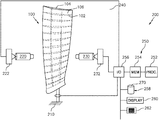
- FIG. 1 is a schematic view of a nondestructive ultrasonic damage detection system.
- FIG. 2 is a block diagram representing a method of inspection using the nondestructive ultrasonic damage detection system.
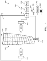
- FIG. 3 is a representation of the method of inspection.
- FIG. 1 schematically illustrates a nondestructive ultrasonic damage detection system 200 .
- the system 200 utilizes models of internal component structure to guide the detection, computation of shape features, and classification of defects based on those shape features.
- the techniques are particularly applicable to composite material manufacturing defects such as disbonding or delamination within a component 100 .
- the component 100 for example a fan blade of a gas turbine engine, may have a substrate 102 , a cover 104 , and a rigid internal structure 106 .
- the cover 104 is bonded to the internal structure 106 which, in turn, is either bonded to, or is an integral part of, the substrate 102 . While this disclosure is taught with respect to a fan blade, it is explicitly contemplated that the teaching herein is applicable to both natural and manufactured composite objects with internal structure.
- the nondestructive ultrasonic damage detection system 200 includes a fixture 210 to retain the component 100 , a first pulse echo ultrasonic transducer 220 , a first position control 222 to position the first pulse echo ultrasonic transducer 220 , a second pulse echo ultrasonic transducer 230 , a second position control 232 to position the second pulse echo ultrasonic transducer 230 , and a control system 250 .
- the first and second pulse echo ultrasonic transducers 220 , 230 transmit short-duration ultrasound pulses into the region to be studied, and echo signals resulting from scattering and reflection are detected and may be processed and displayed.
- Pulse echo ultrasonic transducers 220 , 230 may also receive through-transmission ultrasonic pulses from pulse echo ultrasonic transducers 230 , 220 , respectively. Since an ultrasonic transmitter is also effectively an ultrasonic receiver, no additional hardware is needed for pulse echo ultrasonic transducers 220 , 230 to operate as bi-directional through-transmission hardware.
- the first and second position control 222 , 232 may be a computer numerical control (CNC) robotic manipulator system that moves the first and second pulse echo ultrasonic transducer 220 , 230 in response to the control system 250 .
- the control system 250 may include hardware, firmware, and/or software components that are configured to perform the functions disclosed herein, including the operation of the first and second positon control 222 , 232 . While not specifically shown, the control system 250 may include other computing devices (e.g., servers, mobile computing devices, and the like) and computer aided manufacturer (CAM) systems which may be in communication with each other and/or the control system 250 via a communication network to perform one or more of the disclosed functions.
- computing devices e.g., servers, mobile computing devices, and the like
- CAM computer aided manufacturer
- the control system 250 may include at least one processor 252 (e.g., a controller, microprocessor, microcontroller, digital signal processor, and the like), memory 254 , and an input/output (I/O) subsystem 256 .
- the control system 250 may be embodied as any type of computing device (e.g., a workstation, an embedded computer, an FPGA, a tablet computer, smart phone, body-mounted device or wearable device, and the like, a server, an enterprise computer system, a network of computers, a combination of computers and other electronic devices, or other electronic devices).
- the I/O subsystem 256 typically includes, for example, an I/O controller, a memory controller, and one or more I/O ports.
- the processor 252 and the I/O subsystem 256 are communicatively coupled to the memory 254 .
- the memory 254 may be embodied as any type of computer memory device (e.g., volatile memory such as various forms of random access memory).
- the I/O subsystem 256 may also be communicatively coupled to a number of hardware, firmware, and/or software components, including a data storage device 258 , a display 260 , and a user interface (UI) subsystem 262 .
- the data storage device 258 may include one or more hard drives or other suitable persistent storage devices (e.g., flash memory, memory cards, memory sticks, and/or others).
- a database 270 for models of the component may reside at least temporarily in the data storage device 258 and/or other data storage devices (e.g., data storage devices that are “in the cloud” or otherwise connected to the control system 250 by a network).
- the models of the component 100 may be an as-designed model, an as-built model, a previous condition model, and the like.
- one disclosed non-limiting embodiment of a method 300 for nondestructive component inspection initially includes locating the component in the fixture 210 of the system 200 (step 302 ). Although a fan blade of a gas turbine engine is illustrated as the representative example component, any such composite component can be inspected by the system 200 .
- the first positon control 222 positons the first pulse echo ultrasonic transducer 220 to determine a first pulse-echo scan 120 from a first side of the component 100 and a second positon control 232 positons the second pulse echo ultrasonic transducer 230 from a second side of the component 100 .
- the first and second positon control 222 , 232 move the respective first and second pulse echo ultrasonic transducer 220 , 230 guided by the control system 250 in response to a first registration model 110 of the first side of the component and a second registration model 112 of the second side of the component.
- the models 110 , 112 include the rigid internal structure 106 such that predetermined areas can be delineated in association therewith. That is, the predetermined areas identify the location of the rigid internal structure 106 from the associated sides of the component 100 to isolate particular areas which both transmit ultrasonic energy and may be subject to defects such as disbonding and/or delamination.
- the internal structure 106 is registered via one or more models 110 , 112 of the component 100 . Multiple models may be required since the rigid internal structure 106 on one side of component 100 need not be directly aligned with the rigid internal structure 106 on the other side of component 110 .
- the registered structural models to both front and back pulse-echo images allow guidance of the first and second pulse echo ultrasonic transducer 220 , 230 and reasoning about expected through-transmission acoustic energy for defect detection.
- the models may be an as-designed model, an as-built model, a previous condition model, and the like.
- the registration may make use of edges of the composite component 100 to scale, rotate, and or translate the model to elucidate the internal structure 106 from the perspective of the first and second pulse echo ultrasonic transducer 220 , 230 for automated reasoning about the predetermined areas at which a defect may occur. That is, the registered models may be used to constrain detection of defects in the pulse-echo scans 120 , 122 or the corresponding through-transmission scans (one direction shown: 130 , 140 ) to only the predetermined areas.
- the registered models may also be used to guide the first and second pulse echo ultrasonic transducer 220 , 230 since, for efficient inspection speed, only the predetermined areas adjacent to the rigid internal structure 106 may need to be scanned.
- the predetermined areas with the rigid internal structure 106 from the models are used to influence the detection of damage, particularly where the damage manifests as a ‘distorted pattern’ in the pulse-echo or through-transmission scan.
- This influencing of the detection of damage may be based on, for example, the known internal structure, as initialization of an active contour shape determination, a geometric restriction for the predetermined area over which statistical characterization is performed, as priors in a Bayesian estimation, or other technique that limits portions of the pulse-echo scan.
- a disbond may be detected because it appears at a particular location with respect to the known location of the rigid internal structure 106 where the identical pulse-echo scan imagery that is not at a known location of the rigid internal structure 106 may be ignored.
- the through-transmission excitation is largely carried by the rigid internal structure 106 and, by using the models 110 , 112 , the expected energy transmission may be compared to the actual energy transmission for the detection of defects as represented by the interrupted energy path “D” in the through-transmission scan 140 due to a defect.
- the pulse-echo scan 120 of the first side of the component produces pulse-echo scan imagery substantially representing the top of the internal structure 106 .
- the pulse-echo scan 122 of the back of the component 100 produces an image substantially representing the bottom of the internal structure 106 .
- the models 110 , 112 of the top (bottom) structure may be registered to the respective top (bottom) pulse-echo scan imagery using, for instance, a random consensus (RANSAC) algorithm based on computed features where the features may include SIFT, SURF, ASIFT, other SIFT variants, Harris Corner features, SUSAN, FAST, a Phase Correlation, a Normalized Cross-Correlation, GLOH, BRIEF, CenSure/STAR, ORB, and the like.
- RANSAC random consensus
- the models 110 , 112 may be used to separately guide an acoustically-aligned through-transmission scan (one direction shown: 130 , 140 ) where the transducers are aligned along the acoustic transmission path rather than being simply opposite each other along an axis orthogonal to the component.
- the pulse-echo or through-transmission scans may be normalized and compared (step 306 ) with the models in the database 270 to initialize or constrain detection of damage in the pulse-echo or through-transmission scan features to only the relevant area or shape.
- the pulse-echo or through-transmission scans of the subject component may be normalized to account for overall differences in excitation energy, different gain in the transmitter or receiver, and the like.
- both the internal structure 106 and how any defects (step 308 ) may manifest are guided by the models 110 , 112 .
- the pulse-echo scans are used for guidance, while through-transmission may be used for damage detection.
- pulse-echo may be used for damage detection.
- the detection of defects may use a difference between the through-transmission of the subject component and a “gold model” scan derived from previous experimentation, an expected energy model derived from the physics of acoustic transmission, and the like.
- the gold model may be derived from the through-transmission data.
- the gold model may be those data values within a predetermined number of standard deviations from the mean of the data values.
- the difference may be analyzed by a statistical detector (hypothesis detector) where one hypothesis is that the differential energy is zero and the other hypothesis is that the differential energy is non-zero.
- PCA principal components analysis
- RPCA robust PCA
- SVM support vector machines
- LDA linear discriminant analysis
- EM expectation maximization
- Boosting Dictionary Matching
- ML maximum likelihood estimation
- MAP maximum a priori estimation
- LS least squares estimation
- NLS non-linear LS estimation
- Bayesian Estimation Bayesian Estimation, and the like.
- Additional morphological filtering may be used to effectively ignore very small detections that may result from noise or that would not significantly affect bond strength and component reliability.
- defects can be detected via a deep learning classifier trained from available data, such as a library of user characterized damage examples stored within the database 270 .
- Deep learning is the process of training or adjusting the weights of a deep neural network.
- the deep neural network is a deep convolutional neural network trained by presenting an error map or partial error map to an input layer and a damage/no-damage label to an output layer. The training of a deep convolutional network proceeds layer-wise and does not require a label until the output layer is trained.
- the weights of the deep network's layers are adapted, typically by a stochastic gradient descent algorithm, to produce a correct classification.
- the deep learning training may use only partially labeled data, only fully labeled data, or only implicitly labeled data, or may use unlabeled data for initial or partial training with only a final training on labeled data.
- the component may then be classified (step 310 ) based on the defect determination into binary (e.g. reject, accept) or multi-class categories (e.g., a score), using algorithms such as a logistics regression, nearest neighbor metrics, deep neural networks, Bayesian estimation, support vector machines, decision trees, random forests, and the like.
- binary e.g. reject, accept
- multi-class categories e.g., a score
- the nondestructive ultrasonic damage detection system 200 permits inspection of components to detect defects by registering a model and constraining the analytics based on the model.
- the nondestructive ultrasonic damage detection system 200 facilitates automated inspection that reduces cost of poor quality (COPQ) from faulty human visual inspection; reduces turn-backs from subsequent inspector disagreement; reduces dependence on increasingly scarce skilled inspectors; reduces inspection time and cost, increases inspector efficiency; and gathers machine-readable data on component condition for repair scheduling, life estimation, (re)design, and training.
- COPQ cost of poor quality
Landscapes
- Physics & Mathematics (AREA)
- Health & Medical Sciences (AREA)
- Life Sciences & Earth Sciences (AREA)
- Chemical & Material Sciences (AREA)
- Analytical Chemistry (AREA)
- Biochemistry (AREA)
- General Health & Medical Sciences (AREA)
- General Physics & Mathematics (AREA)
- Immunology (AREA)
- Pathology (AREA)
- Acoustics & Sound (AREA)
- Engineering & Computer Science (AREA)
- Signal Processing (AREA)
- Investigating Or Analyzing Materials By The Use Of Ultrasonic Waves (AREA)
Abstract
Description
Claims (15)
Priority Applications (1)
| Application Number | Priority Date | Filing Date | Title |
|---|---|---|---|
| US15/971,270 US10928362B2 (en) | 2018-05-04 | 2018-05-04 | Nondestructive inspection using dual pulse-echo ultrasonics and method therefor |
Applications Claiming Priority (1)
| Application Number | Priority Date | Filing Date | Title |
|---|---|---|---|
| US15/971,270 US10928362B2 (en) | 2018-05-04 | 2018-05-04 | Nondestructive inspection using dual pulse-echo ultrasonics and method therefor |
Publications (2)
| Publication Number | Publication Date |
|---|---|
| US20190339234A1 US20190339234A1 (en) | 2019-11-07 |
| US10928362B2 true US10928362B2 (en) | 2021-02-23 |
Family
ID=68385063
Family Applications (1)
| Application Number | Title | Priority Date | Filing Date |
|---|---|---|---|
| US15/971,270 Active 2039-04-04 US10928362B2 (en) | 2018-05-04 | 2018-05-04 | Nondestructive inspection using dual pulse-echo ultrasonics and method therefor |
Country Status (1)
| Country | Link |
|---|---|
| US (1) | US10928362B2 (en) |
Cited By (4)
| Publication number | Priority date | Publication date | Assignee | Title |
|---|---|---|---|---|
| US20210133295A1 (en) * | 2019-11-06 | 2021-05-06 | United Technologies Corporation | Parametric component design process |
| US11885767B2 (en) | 2021-06-21 | 2024-01-30 | Rtx Corporation | Automated scan data quality assessment in ultrasonic testing |
| US11913911B2 (en) | 2021-06-21 | 2024-02-27 | Rtx Corporation | System and method for dual pulse-echo sub-surface detection |
| US12265059B2 (en) | 2021-06-21 | 2025-04-01 | Rtx Corporation | System and method for automated indication confirmation in ultrasonic testing |
Families Citing this family (14)
| Publication number | Priority date | Publication date | Assignee | Title |
|---|---|---|---|---|
| US11079285B2 (en) | 2018-05-04 | 2021-08-03 | Raytheon Technologies Corporation | Automated analysis of thermally-sensitive coating and method therefor |
| US10943320B2 (en) | 2018-05-04 | 2021-03-09 | Raytheon Technologies Corporation | System and method for robotic inspection |
| US11268881B2 (en) | 2018-05-04 | 2022-03-08 | Raytheon Technologies Corporation | System and method for fan blade rotor disk and gear inspection |
| US10902664B2 (en) | 2018-05-04 | 2021-01-26 | Raytheon Technologies Corporation | System and method for detecting damage using two-dimensional imagery and three-dimensional model |
| US10914191B2 (en) | 2018-05-04 | 2021-02-09 | Raytheon Technologies Corporation | System and method for in situ airfoil inspection |
| US20230094981A1 (en) * | 2019-11-29 | 2023-03-30 | Ams Sensors Singapore Pte. Ltd. | Apparatus for monitoring mechanical integrity of an eye-safety component of an illuminator |
| EP4064963B1 (en) * | 2019-11-29 | 2024-08-07 | ams Sensors Singapore Pte. Ltd. | Apparatus for monitoring mechanical integrity of an eye-safety component of an illuminator |
| JP7570842B2 (en) * | 2020-07-31 | 2024-10-22 | 株式会社東芝 | Ultrasound image evaluation device and ultrasound image evaluation method |
| JP7428616B2 (en) * | 2020-08-27 | 2024-02-06 | 株式会社日立パワーソリューションズ | Ultrasonic inspection equipment and ultrasonic inspection method |
| CN115032276A (en) * | 2021-03-04 | 2022-09-09 | 中国航发商用航空发动机有限责任公司 | Ultrasonic detection method for complex composite material part |
| US12553862B2 (en) * | 2023-07-07 | 2026-02-17 | The Boeing Company | Method and apparatus for analyzing a composite structure |
| US20260092898A1 (en) * | 2024-10-01 | 2026-04-02 | Rtx Corporation | Automated method and system for ultrasonically inspecting components |
| US20260092897A1 (en) * | 2024-10-01 | 2026-04-02 | Rtx Corporation | Automated method and system for ultrasonically inspecting components |
| CN121208150B (en) * | 2025-11-26 | 2026-04-24 | 之江实验室 | Ultrasonic two-dimensional phased array probe and three-dimensional imaging method |
Citations (205)
| Publication number | Priority date | Publication date | Assignee | Title |
|---|---|---|---|---|
| US3804397A (en) | 1971-08-19 | 1974-04-16 | Gco | Automatic positioning vacuum cup |
| US4402053A (en) | 1980-09-25 | 1983-08-30 | Board Of Regents For Education For The State Of Rhode Island | Estimating workpiece pose using the feature points method |
| US4403294A (en) | 1979-11-30 | 1983-09-06 | Hitachi, Ltd. | Surface defect inspection system |
| US4873651A (en) | 1987-04-21 | 1989-10-10 | Case Western Reserve University | Method and apparatus for reconstructing three-dimensional surfaces from two-dimensional images |
| US5064291A (en) | 1990-04-03 | 1991-11-12 | Hughes Aircraft Company | Method and apparatus for inspection of solder joints utilizing shape determination from shading |
| US5119678A (en) | 1989-12-26 | 1992-06-09 | General Electric Company | Pulse echo and through transmission ultra-sound |
| JPH06235700A (en) | 1993-02-09 | 1994-08-23 | Toyota Motor Corp | Defective painting inspection system |
| US5345514A (en) | 1991-09-16 | 1994-09-06 | General Electric Company | Method for inspecting components having complex geometric shapes |
| US5345515A (en) | 1990-05-28 | 1994-09-06 | Kanebo Ltd. | Method and apparatus for inspecting the cleanliness of top slibers |
| US5351078A (en) | 1954-12-24 | 1994-09-27 | Lemelson Medical, Education & Research Foundation Limited Partnership | Apparatus and methods for automated observation of objects |
| DE19710743A1 (en) | 1997-03-14 | 1998-09-24 | Siemens Ag | Gas-turbine blades crack testing and crack depth measurement |
| US5963328A (en) | 1997-08-28 | 1999-10-05 | Nissan Motor Co., Ltd. | Surface inspecting apparatus |
| US6023637A (en) | 1997-03-31 | 2000-02-08 | Liu; Zhong Qi | Method and apparatus for thermal radiation imaging |
| US6153889A (en) | 1998-03-20 | 2000-11-28 | Rolls-Royce Plc | Method and an apparatus for inspecting articles |
| US6177682B1 (en) | 1998-10-21 | 2001-01-23 | Novacam Tyechnologies Inc. | Inspection of ball grid arrays (BGA) by using shadow images of the solder balls |
| US6271520B1 (en) | 1998-03-23 | 2001-08-07 | University Of Arkansas | Item defect detection apparatus and method |
| US6399948B1 (en) | 1999-09-16 | 2002-06-04 | Wayne State University | Miniaturized contactless sonic IR device for remote non-destructive inspection |
| US6434267B1 (en) | 1998-03-26 | 2002-08-13 | Rolls-Royce Plc | Interpretation of thermal paint |
| US20020121602A1 (en) | 1999-09-16 | 2002-09-05 | Thomas Robert L. | Hand-held sound source gun for infrared imaging of sub-surface defects in materials |
| US6462813B1 (en) | 1996-04-12 | 2002-10-08 | Perceptron, Inc. | Surface defect inspection system and method |
| US20020167660A1 (en) | 2001-05-09 | 2002-11-14 | Testship Automatic Test Solutions Ltd. | Illumination for integrated circuit board inspection |
| US20030117395A1 (en) | 2001-08-17 | 2003-06-26 | Byoungyi Yoon | Method and system for calculating a photographing ratio of a camera |
| US6690016B1 (en) | 1998-02-10 | 2004-02-10 | Philip Morris Incorporated | Process control by transient thermography |
| US20040089812A1 (en) | 2002-08-28 | 2004-05-13 | Wayne State University | System and method for multiple mode flexible excitation and acoustic chaos in sonic infrared imaging |
| US20040089811A1 (en) | 2002-11-12 | 2004-05-13 | Siemens Westinghouse Power Corporation | Methods and system for ultrasonic thermographic non-destructive examination for enhanced defect determination |
| US6737648B2 (en) | 2000-11-22 | 2004-05-18 | Carnegie Mellon University | Micromachined infrared sensitive pixel and infrared imager including same |
| US20040139805A1 (en) | 2002-10-31 | 2004-07-22 | Alstom (Switzerland) Ltd | Non-destructive method of detecting defects in braze-repaired cracks |
| US6804622B2 (en) | 2001-09-04 | 2004-10-12 | General Electric Company | Method and apparatus for non-destructive thermal inspection |
| US20040201672A1 (en) | 2003-04-11 | 2004-10-14 | Sridhar Varadarajan | System and method for warning drivers based on road curvature |
| US20040240600A1 (en) | 2003-05-30 | 2004-12-02 | Siemens Westinghouse Power Corporation | Positron annihilation for inspection of land based industrial gas turbine components |
| US20040247170A1 (en) | 2003-06-06 | 2004-12-09 | Furze Paul A. | Use of patterned, structured light to detect and measure surface defects on a golf ball |
| US20040245469A1 (en) | 1999-09-16 | 2004-12-09 | Wayne State University | Hand-held sound source for sonic infrared imaging of defects in materials |
| US20050008215A1 (en) | 1999-12-02 | 2005-01-13 | Shepard Steven M. | System for generating thermographic images using thermographic signal reconstruction |
| US20050113060A1 (en) | 2003-10-17 | 2005-05-26 | Lowery Kenneth E. | Wireless network system |
| US6907358B2 (en) | 2003-01-30 | 2005-06-14 | General Electric Company | Eddy current inspection method |
| US20050151083A1 (en) | 2002-08-28 | 2005-07-14 | Wayne State University | System and method for generating chaotic sound for sonic infrared imaging of defects in materials |
| US6965120B1 (en) | 1998-12-21 | 2005-11-15 | Hottinger Maschinenbau Gmbh | Method and apparatus for quality control in the manufacture of foundry cores or core packets |
| US20050276907A1 (en) | 2004-06-14 | 2005-12-15 | Harris Kevin M | Apparatus and method for inspecting golf balls using infrared radiation |
| US20060012790A1 (en) | 2004-06-14 | 2006-01-19 | Furze Paul A | Apparatus and method for inspecting golf balls using spectral analysis |
| US7026811B2 (en) | 2004-03-19 | 2006-04-11 | General Electric Company | Methods and apparatus for eddy current inspection of metallic posts |
| US20060078193A1 (en) | 2004-10-08 | 2006-04-13 | Siemens Westinghouse Power Corporation | Method of visually inspecting turbine blades and optical inspection system therefor |
| US20060086912A1 (en) | 2004-10-22 | 2006-04-27 | Northrop Grumman Corporation | System for detecting structural defects and features utilizing blackbody self-illumination |
| US7064330B2 (en) | 2003-04-30 | 2006-06-20 | United Technologies Corporation | Infrared defect detection via broad-band acoustics |
| US7119338B2 (en) | 2002-12-20 | 2006-10-10 | The Boeing Company | Translatable ultrasonic thermography inspection apparatus and method |
| US7129492B2 (en) | 2003-07-29 | 2006-10-31 | Toyota Motor Manufacturing North America, Inc. | Systems and methods for inspecting coatings |
| US20070007733A1 (en) | 2005-07-08 | 2007-01-11 | General Electric Company | Vaccum-assisted fixture for holding a part |
| US20070017297A1 (en) | 2005-07-21 | 2007-01-25 | The Boeing Company | Non-destructive inspection system and associated method |
| US7190162B2 (en) | 2004-07-23 | 2007-03-13 | General Electric Company | Methods and apparatus for inspecting a component |
| US7220966B2 (en) | 2003-07-29 | 2007-05-22 | Toyota Motor Manufacturing North America, Inc. | Systems and methods for inspecting coatings, surfaces and interfaces |
| US7233867B2 (en) | 2005-04-06 | 2007-06-19 | General Electric Company | Eddy current inspection method and system |
| US7240556B2 (en) | 2005-03-14 | 2007-07-10 | The Boeing Company | Angle beam shear wave through-transmission ultrasonic testing apparatus and method |
| US7272529B2 (en) | 2005-07-08 | 2007-09-18 | Honeywell International, Inc. | Dual wall turbine blade ultrasonic wall thickness measurement technique |
| US7313961B2 (en) | 2005-04-26 | 2008-01-01 | General Electric Company | Method and apparatus for inspecting a component |
| US20080022775A1 (en) | 2006-07-31 | 2008-01-31 | University Of Dayton | Non-contact thermo-elastic property measurement and imaging system for quantitative nondestructive evaluation of materials |
| US20080053234A1 (en) | 2006-09-05 | 2008-03-06 | United Technologies Corporation | Inverse thermal acoustic imaging part inspection |
| US20080111074A1 (en) | 2004-10-22 | 2008-05-15 | Northrop Grumman Corporation | Method for infrared imaging of substrates through coatings |
| US20080183402A1 (en) | 2007-01-30 | 2008-07-31 | The Boeing Company | Methods and Systems for Automatically Assessing and Reporting Structural Health |
| US7415882B2 (en) | 2005-12-19 | 2008-08-26 | The Boeing Company | Methods and systems for inspection of composite assemblies |
| EP1961919A2 (en) | 2007-02-21 | 2008-08-27 | United Technologies Corporation | Variable rotor blade for gas turbine engine |
| US20080229834A1 (en) | 2007-03-19 | 2008-09-25 | The Boeing Company | Method And Apparatus For Inspecting A Workpiece With Angularly Offset Ultrasonic Signals |
| US20080247636A1 (en) | 2006-03-20 | 2008-10-09 | Siemens Power Generation, Inc. | Method and System for Interactive Virtual Inspection of Modeled Objects |
| US20080247635A1 (en) | 2006-03-20 | 2008-10-09 | Siemens Power Generation, Inc. | Method of Coalescing Information About Inspected Objects |
| US7446886B2 (en) | 2003-10-02 | 2008-11-04 | Daimler Ag | Three-dimensional reconstruction of surface profiles |
| US20090000382A1 (en) | 2006-07-31 | 2009-01-01 | University Of Dayton | Non-contact acousto-thermal method and apparatus for detecting incipient damage in materials |
| US20090010507A1 (en) | 2007-07-02 | 2009-01-08 | Zheng Jason Geng | System and method for generating a 3d model of anatomical structure using a plurality of 2d images |
| US20090066939A1 (en) | 2007-09-07 | 2009-03-12 | General Electric Company | Method for automatic identification of defects in turbine engine blades |
| US20090128643A1 (en) | 2005-01-18 | 2009-05-21 | Tetsujiro Kondo | Image Pickup Apparatus, Method for Capturing Image, and Method for Designing Image Pickup Apparatus |
| US20090252987A1 (en) | 2008-04-02 | 2009-10-08 | United Technologies Corporation | Inspection and repair process using thermal acoustic imaging |
| US7602963B2 (en) | 2006-01-10 | 2009-10-13 | General Electric Company | Method and apparatus for finding anomalies in finished parts and/or assemblies |
| US20090279772A1 (en) | 2008-05-12 | 2009-11-12 | General Electric Company | Method and System for Identifying Defects in NDT Image Data |
| US20090312956A1 (en) | 1999-12-22 | 2009-12-17 | Zombo Paul J | Method and apparatus for measuring on-line failure of turbine thermal barrier coatings |
| US7689030B2 (en) | 2005-12-21 | 2010-03-30 | General Electric Company | Methods and apparatus for testing a component |
| US7738725B2 (en) | 2003-03-19 | 2010-06-15 | Mitsubishi Electric Research Laboratories, Inc. | Stylized rendering using a multi-flash camera |
| US20100212430A1 (en) * | 2007-09-28 | 2010-08-26 | Krautkramer Japan Co., Ltd. | Ultrasonic flaw detection method and ultrasonic flaw detection equipment |
| US20100220910A1 (en) | 2009-03-02 | 2010-09-02 | General Electric Company | Method and system for automated x-ray inspection of objects |
| US7823451B2 (en) | 2008-05-06 | 2010-11-02 | The Boeing Company | Pulse echo/through transmission ultrasonic testing |
| US20110062339A1 (en) | 2009-09-16 | 2011-03-17 | Ruhge Forrest R | System and Method for Analysis of Ultrasonic Power Coupling During Acoustic Thermography |
| US20110083705A1 (en) | 2008-11-06 | 2011-04-14 | Stone Roy L | Engine wash system |
| US20110119020A1 (en) | 2009-11-17 | 2011-05-19 | Meyer Tool, Inc. | Apparatus and Method For Measurement of the Film Cooling Effect Produced By Air Cooled Gas Turbine Components |
| US20110123093A1 (en) | 2009-11-25 | 2011-05-26 | Toyota Motor Engineering & Manufacturing North America, Inc. | Systems and methods for detecting defects in coatings utilizing color-based thermal mismatch |
| US7966883B2 (en) | 2006-12-06 | 2011-06-28 | Lockheed Martin Corporation | Non-destructive inspection using laser-ultrasound and infrared thermography |
| US8050491B2 (en) | 2003-12-17 | 2011-11-01 | United Technologies Corporation | CAD modeling system and method |
| US20110299752A1 (en) | 2010-06-04 | 2011-12-08 | Uchicago Argonne, Llc | Method for implementing depth deconvolution algorithm for enhanced thermal tomography 3d imaging |
| US20110302694A1 (en) | 2008-04-03 | 2011-12-15 | University Of Washington | Clinical force sensing glove |
| US20120154599A1 (en) | 2010-12-17 | 2012-06-21 | Pelco Inc. | Zooming factor computation |
| US8221825B2 (en) | 2009-03-30 | 2012-07-17 | Alstom Technology Ltd. | Comprehensive method for local application and local repair of thermal barrier coatings |
| US20120188380A1 (en) | 2010-05-03 | 2012-07-26 | Pratt & Whitney | Machine Tool - Based, Optical Coordinate Measuring Machine Calibration Device |
| US8239424B2 (en) | 2006-03-02 | 2012-08-07 | Thermoteknix Systems Ltd. | Image alignment and trend analysis features for an infrared imaging system |
| US20120249959A1 (en) | 2011-03-31 | 2012-10-04 | The Hong Kong Polytechnic University | Apparatus and method for non-invasive diabetic retinopathy detection and monitoring |
| US20120275667A1 (en) | 2011-04-29 | 2012-11-01 | Aptina Imaging Corporation | Calibration for stereoscopic capture system |
| US20120293647A1 (en) | 2011-05-16 | 2012-11-22 | General Electric Company | Method and system for multi-functional embedded sensors |
| US20130028478A1 (en) | 2010-05-04 | 2013-01-31 | St-Pierre Eric | Object inspection with referenced volumetric analysis sensor |
| US20130041614A1 (en) | 2010-03-17 | 2013-02-14 | Thermal Wave Imaging, Inc. | Thermographic Detection of Internal Passageway Blockages |
| US20130070897A1 (en) | 2010-05-28 | 2013-03-21 | Snecma | Method of non-destructive inspection and a device for implementing the method |
| US8413917B2 (en) | 2008-07-30 | 2013-04-09 | Flsmidth A/S | Roller mill with gas duct |
| US20130113914A1 (en) | 2011-11-03 | 2013-05-09 | Pratt & Whitney | System and Method for Automated Borescope Inspection User Interface |
| US20130113916A1 (en) | 2011-11-03 | 2013-05-09 | Pratt & Whitney | System and Method for Multiple Simultaneous Automated Defect Detection |
| US8449176B2 (en) | 2005-08-01 | 2013-05-28 | Thermal Wave Imaging, Inc. | Automated binary processing of thermographic sequence data |
| WO2013088709A1 (en) | 2011-12-15 | 2013-06-20 | パナソニック株式会社 | Endoscope and endoscope system provided with same |
| US20130163849A1 (en) | 2010-09-14 | 2013-06-27 | Ronny Jahnke | Apparatus and method for automatic inspection of through-holes of a component |
| SG191452A1 (en) | 2011-12-30 | 2013-07-31 | Singapore Technologies Dynamics Pte Ltd | Automatic calibration method and apparatus |
| US8520931B2 (en) | 2008-09-24 | 2013-08-27 | Canon Kabushiki Kaisha | Position and orientation measurement apparatus and method thereof |
| US8528317B2 (en) | 2009-08-21 | 2013-09-10 | Snecma | Method and system for detecting the ingestion of an object by an aircraft turbine engine during a mission |
| US20130235897A1 (en) | 2010-09-28 | 2013-09-12 | Astrium Sas | Method and device for non-destructive testing of wind turbine blades |
| US20130250067A1 (en) | 2010-03-29 | 2013-09-26 | Ludwig Laxhuber | Optical stereo device and autofocus method therefor |
| US20140022357A1 (en) | 2012-07-20 | 2014-01-23 | Test Research, Inc. | Three-dimensional image measuring apparatus |
| US20140056507A1 (en) | 2012-08-27 | 2014-02-27 | Joseph D. Doyle | Methods and systems for inspecting a workpiece |
| US8692887B2 (en) | 2010-08-27 | 2014-04-08 | General Electric Company | Thermal imaging method and apparatus for evaluating coatings |
| US20140098836A1 (en) | 2011-06-08 | 2014-04-10 | Rolls-Royce Plc | Temperature indicating paint |
| US20140184786A1 (en) | 2013-01-02 | 2014-07-03 | The Boeing Company | Systems and Methods for Stand-Off Inspection of Aircraft Structures |
| US20140185912A1 (en) | 2012-12-31 | 2014-07-03 | General Electric Company | Methods and Systems for Enhanced Automated Visual Inspection of a Physical Asset |
| US8781209B2 (en) | 2011-11-03 | 2014-07-15 | United Technologies Corporation | System and method for data-driven automated borescope inspection |
| US8781210B2 (en) | 2011-11-09 | 2014-07-15 | United Technologies Corporation | Method and system for automated defect detection |
| US20140198185A1 (en) | 2013-01-17 | 2014-07-17 | Cyberoptics Corporation | Multi-camera sensor for three-dimensional imaging of a circuit board |
| US20140200832A1 (en) | 2011-06-14 | 2014-07-17 | The Boeing Company | Autonomous Non-Destructive Evaluation System for Aircraft Structures |
| US8792705B2 (en) | 2011-11-03 | 2014-07-29 | United Technologies Corporation | System and method for automated defect detection utilizing prior data |
| US8913825B2 (en) | 2012-07-16 | 2014-12-16 | Mitsubishi Electric Research Laboratories, Inc. | Specular edge extraction using multi-flash imaging |
| CA2820732A1 (en) | 2013-06-27 | 2014-12-27 | Systemes Tecscan Inc. | Method and apparatus for scanning an object |
| US20150046098A1 (en) | 2012-03-20 | 2015-02-12 | Baylor University | Method and system of non-destructive testing for composites |
| US20150041654A1 (en) | 2013-08-08 | 2015-02-12 | Stichting SRON - Netherlands Institute for Space Research | Method and system for inspection of composite assemblies using terahertz radiation |
| US8983794B1 (en) | 2010-10-04 | 2015-03-17 | The Boeing Company | Methods and systems for non-destructive composite evaluation and repair verification |
| US20150086083A1 (en) | 2013-09-25 | 2015-03-26 | Sikorsky Aircraft Corporation | Structural hot spot and critical location monitoring system and method |
| US20150128709A1 (en) | 2013-11-14 | 2015-05-14 | The Boeing Company | Structural bond inspection |
| US9037381B2 (en) | 2013-02-19 | 2015-05-19 | Rolls-Royce Plc | Determining the deterioration of a gas turbine engine in use |
| US20150138342A1 (en) | 2013-11-19 | 2015-05-21 | United Technologies Corporation | System and method to determine visible damage |
| US9046497B2 (en) | 2011-03-09 | 2015-06-02 | Rolls-Royce Corporation | Intelligent airfoil component grain defect inspection |
| US9066028B1 (en) | 2010-01-08 | 2015-06-23 | The United States Of America As Represented By The Administator Of The National Aeronautics And Space Administration | Methods and systems for measurement and estimation of normalized contrast in infrared thermography |
| US20150185128A1 (en) | 2013-12-26 | 2015-07-02 | The Boeing Company | Detection and Assessment of Damage to Composite Structure |
| US20150233714A1 (en) | 2014-02-18 | 2015-08-20 | Samsung Electronics Co., Ltd. | Motion sensing method and user equipment thereof |
| US9116071B2 (en) | 2012-01-31 | 2015-08-25 | Siemens Energy, Inc. | System and method for visual inspection and 3D white light scanning of off-line industrial gas turbines and other power generation machinery |
| JP2015161247A (en) | 2014-02-27 | 2015-09-07 | 三菱重工業株式会社 | Wind turbine blade damage detection method and wind turbine |
| US20150253266A1 (en) | 2012-10-19 | 2015-09-10 | Resodyn Corporation | Methods and systems for detecting flaws in an object |
| US9134280B2 (en) | 2009-02-25 | 2015-09-15 | Saipem S.P.A. | Method for testing pipeline welds using ultrasonic phased arrays |
| US9146205B2 (en) | 2011-05-10 | 2015-09-29 | Areva Inc. | Vibrothermographic weld inspections |
| US9151698B2 (en) | 2010-04-23 | 2015-10-06 | Siemens Aktiengesellschaft | Testing system for examining turbine blades |
| US9154743B2 (en) | 2012-01-31 | 2015-10-06 | Siemens Energy, Inc. | System and method for optical inspection of off-line industrial gas turbines and other power generation machinery while in turning gear mode |
| US20150314901A1 (en) | 2014-05-02 | 2015-11-05 | Pouch Pac Innovations, Llc | Fitment delivery system |
| US20160012588A1 (en) | 2014-07-14 | 2016-01-14 | Mitsubishi Electric Research Laboratories, Inc. | Method for Calibrating Cameras with Non-Overlapping Views |
| US9240049B2 (en) | 2012-08-21 | 2016-01-19 | Pelican Imaging Corporation | Systems and methods for measuring depth using an array of independently controllable cameras |
| US20160043008A1 (en) | 2013-03-15 | 2016-02-11 | Todd Murray | Optical acoustic substrate assessment system and method |
| US9300865B2 (en) | 2014-01-24 | 2016-03-29 | Goodrich Corporation | Random imaging |
| US9305345B2 (en) | 2014-04-24 | 2016-04-05 | General Electric Company | System and method for image based inspection of an object |
| US20160109283A1 (en) | 2013-05-30 | 2016-04-21 | Snecma | Improved method for inspection by the transmission of ultrasounds |
| US20160178532A1 (en) | 2014-12-19 | 2016-06-23 | General Electric Company | System and method for engine inspection |
| WO2016112018A1 (en) | 2015-01-06 | 2016-07-14 | Sikorsky Aircraft Corporation | Structural masking for progressive health monitoring |
| WO2016123508A1 (en) | 2015-01-29 | 2016-08-04 | The Regents Of The University Of California | Patterned-illumination systems adopting a computational illumination |
| US20160241793A1 (en) | 2015-02-13 | 2016-08-18 | Qualcomm Incorporated | Systems and methods for power optimization for imaging devices with dual cameras |
| US20160284098A1 (en) | 2015-03-23 | 2016-09-29 | Kabushiki Kaisha Toshiba | Image processing device, image processing method, computer program product, and image processing system |
| US9458735B1 (en) | 2015-12-09 | 2016-10-04 | General Electric Company | System and method for performing a visual inspection of a gas turbine engine |
| US9467628B2 (en) | 2014-08-26 | 2016-10-11 | Sensors Unlimited, Inc. | High dynamic range image sensor |
| US9465385B2 (en) | 2013-01-11 | 2016-10-11 | Ckd Corporation | Inspecting device monitoring system |
| US9471057B2 (en) | 2011-11-09 | 2016-10-18 | United Technologies Corporation | Method and system for position control based on automated defect detection feedback |
| US9476842B2 (en) | 2010-05-03 | 2016-10-25 | United Technologies Corporation | On-the-fly dimensional imaging inspection |
| US9476798B2 (en) | 2014-02-21 | 2016-10-25 | General Electric Company | On-line monitoring of hot gas path components of a gas turbine |
| US20160314571A1 (en) | 2015-04-21 | 2016-10-27 | United Technologies Corporation | Method and System for Automated Inspection Utilizing A Multi-Modal Database |
| US9483820B2 (en) | 2014-05-20 | 2016-11-01 | General Electric Company | Method and system for detecting a damaged component of a machine |
| WO2016176524A1 (en) | 2015-04-29 | 2016-11-03 | Magna International Inc. | Flexible fixturing |
| US9488592B1 (en) | 2011-09-28 | 2016-11-08 | Kurion, Inc. | Automatic detection of defects in composite structures using NDT methods |
| US20160334284A1 (en) | 2013-12-19 | 2016-11-17 | Margarita KAPLUN MUCHARRAFILLE | System and method for calibrating and characterising instruments for temperature measurement by telemetry |
| US9519844B1 (en) | 2016-01-22 | 2016-12-13 | The Boeing Company | Infrared thermographic methods for wrinkle characterization in composite structures |
| US20170011503A1 (en) | 2013-03-15 | 2017-01-12 | Digital Wind Systems, Inc. | System and Method for Ground Based Inspection of Wind Turbine Blades |
| US20170023505A1 (en) | 2015-07-22 | 2017-01-26 | Leonardo S.P.A. | Method and system of thermographic non-destructive inspection for detecting and measuring volumetric defects in composite material structures |
| US20170052152A1 (en) | 2015-08-21 | 2017-02-23 | The Boeing Company | Analysis of a structure modeled with inconsistencies mapped thereon |
| US9594059B1 (en) | 2015-12-31 | 2017-03-14 | The Boeing Company | System and method for automated bond testing |
| US20170085760A1 (en) | 2015-09-21 | 2017-03-23 | Siemens Energy, Inc. | Method and apparatus for verifying lighting setup used for visual inspection |
| US20170090458A1 (en) | 2015-09-29 | 2017-03-30 | General Electric Company | Methods and systems for network-based detection of component wear |
| US20170122123A1 (en) | 2015-11-03 | 2017-05-04 | Rolls-Royce Plc | Inspection apparatus and methods of inspecting gas turbine engines |
| US20170142302A1 (en) | 2014-07-04 | 2017-05-18 | Millwatchip Pty Ltd | Apparatus for monitoring of grinding mill interior during operation |
| GB2545271A (en) | 2015-12-11 | 2017-06-14 | Airbus Operations Ltd | Determining physical characteristics of a structure |
| US20170184549A1 (en) | 2015-12-29 | 2017-06-29 | General Electric Company | Systems and methods for ultrasonic inspection of turbine components |
| US20170211408A1 (en) | 2016-01-21 | 2017-07-27 | United Technologies Corporation | Heat flux measurement system |
| US20170219815A1 (en) | 2012-01-31 | 2017-08-03 | Siemens Energy, Inc. | Single-axis inspection scope with bendable knuckle and method for internal inspection of power generation machinery |
| US20170221274A1 (en) | 2016-01-28 | 2017-08-03 | Beihang University | Structure self-adaptive 3d model editing method |
| US9734568B2 (en) | 2014-02-25 | 2017-08-15 | Kla-Tencor Corporation | Automated inline inspection and metrology using shadow-gram images |
| US20170234837A1 (en) | 2014-10-24 | 2017-08-17 | Renishaw Plc | Acoustic apparatus and method |
| US20170241286A1 (en) | 2016-02-24 | 2017-08-24 | General Electric Company | Detectable Datum Markers for Gas Turbine Engine Components for Measuring Distortion |
| US20170262965A1 (en) | 2016-03-14 | 2017-09-14 | Sensors Unlimited, Inc. | Systems and methods for user machine interaction for image-based metrology |
| US20170262979A1 (en) | 2016-03-14 | 2017-09-14 | Sensors Unlimited, Inc. | Image correction and metrology for object quantification |
| US20170258391A1 (en) | 2016-03-14 | 2017-09-14 | Sensors Unlimited, Inc. | Multimodal fusion for object detection |
| US20170262986A1 (en) | 2016-03-14 | 2017-09-14 | Sensors Unlimited, Inc. | Image-based signal detection for object metrology |
| US20170262977A1 (en) | 2016-03-14 | 2017-09-14 | Sensors Unlimited, Inc. | Systems and methods for image metrology and user interfaces |
| US20170262985A1 (en) | 2016-03-14 | 2017-09-14 | Sensors Unlimited, Inc. | Systems and methods for image-based quantification for allergen skin reaction |
| US20170270651A1 (en) | 2016-03-18 | 2017-09-21 | Siemens Energy, Inc. | System and method for enhancing visual inspection of an object |
| US20170284971A1 (en) | 2014-09-29 | 2017-10-05 | Renishaw Plc | Inspection apparatus |
| US9785919B2 (en) | 2015-12-10 | 2017-10-10 | General Electric Company | Automatic classification of aircraft component distress |
| US20170297095A1 (en) | 2016-04-15 | 2017-10-19 | U.S.A. As Represented By The Administrator Of The National Aeronautics And Space Administration | System and Method for In-Situ Characterization and Inspection of Additive Manufacturing Deposits Using Transient Infrared Thermography |
| US9804997B2 (en) | 2009-03-12 | 2017-10-31 | Etegent Technologies, Ltd. | Managing non-destructive evaluation data |
| US9808933B2 (en) | 2015-04-03 | 2017-11-07 | GM Global Technology Operations LLC | Robotic system with reconfigurable end-effector assembly |
| US20180002039A1 (en) | 2016-07-01 | 2018-01-04 | United Technologies Corporation | Systems and methods for detecting damage |
| US20180013959A1 (en) | 2016-07-08 | 2018-01-11 | United Technologies Corporation | Method for turbine component qualification |
| US20180019097A1 (en) | 2015-01-26 | 2018-01-18 | Hitachi High-Technologies Corporation | Sample observation method and sample observation device |
| US20180098000A1 (en) * | 2016-10-05 | 2018-04-05 | Samsung Electronics Co., Ltd. | Image processing systems including plurality of image sensors and electronic devices including the same |
| US9981382B1 (en) | 2016-06-03 | 2018-05-29 | X Development Llc | Support stand to reorient the grasp of an object by a robot |
| US20190299542A1 (en) | 2018-03-30 | 2019-10-03 | The Boeing Company | Automated fiber placement end effector with laminar gas cooling jet and infrared image processor for in-situ inspection |
| US10438036B1 (en) | 2015-11-09 | 2019-10-08 | Cognex Corporation | System and method for reading and decoding ID codes on a curved, sloped and/or annular object |
| US20190339235A1 (en) | 2018-05-04 | 2019-11-07 | United Technologies Corporation | Nondestructive inspection using thermoacoustic imagery and method therefor |
| US20190339207A1 (en) | 2018-05-04 | 2019-11-07 | United Technologies Corporation | System and method for flexibly holding workpiece and reporting workpiece location |
| US20190338666A1 (en) | 2018-05-04 | 2019-11-07 | United Technologies Corporation | System and method for in situ airfoil inspection |
| US20190339131A1 (en) | 2018-05-04 | 2019-11-07 | United Technologies Corporation | Automated analysis of thermally-sensitive coating and method therefor |
| US20190342499A1 (en) | 2018-05-04 | 2019-11-07 | United Technologies Corporation | Multi-camera system for simultaneous registration and zoomed imagery |
| US20190340742A1 (en) | 2018-05-04 | 2019-11-07 | United Technologies Corporation | Nondestructive coating imperfection detection system and method therefor |
| US20190339165A1 (en) | 2018-05-04 | 2019-11-07 | United Technologies Corporation | System and method for fan blade rotor disk and gear inspection |
| US20190339206A1 (en) | 2018-05-04 | 2019-11-07 | United Technologies Corporation | System and method for damage detection by cast shadows |
| US20190340805A1 (en) | 2018-05-04 | 2019-11-07 | United Technologies Corporation | System and method for detecting damage using two-dimensional imagery and three-dimensional model |
| US20190340721A1 (en) | 2018-05-04 | 2019-11-07 | United Technologies Corporation | System and method for robotic inspection |
-
2018
- 2018-05-04 US US15/971,270 patent/US10928362B2/en active Active
Patent Citations (225)
| Publication number | Priority date | Publication date | Assignee | Title |
|---|---|---|---|---|
| US5351078A (en) | 1954-12-24 | 1994-09-27 | Lemelson Medical, Education & Research Foundation Limited Partnership | Apparatus and methods for automated observation of objects |
| US3804397A (en) | 1971-08-19 | 1974-04-16 | Gco | Automatic positioning vacuum cup |
| US4403294A (en) | 1979-11-30 | 1983-09-06 | Hitachi, Ltd. | Surface defect inspection system |
| US4402053A (en) | 1980-09-25 | 1983-08-30 | Board Of Regents For Education For The State Of Rhode Island | Estimating workpiece pose using the feature points method |
| US4873651A (en) | 1987-04-21 | 1989-10-10 | Case Western Reserve University | Method and apparatus for reconstructing three-dimensional surfaces from two-dimensional images |
| US5119678A (en) | 1989-12-26 | 1992-06-09 | General Electric Company | Pulse echo and through transmission ultra-sound |
| US5064291A (en) | 1990-04-03 | 1991-11-12 | Hughes Aircraft Company | Method and apparatus for inspection of solder joints utilizing shape determination from shading |
| US5345515A (en) | 1990-05-28 | 1994-09-06 | Kanebo Ltd. | Method and apparatus for inspecting the cleanliness of top slibers |
| US5345514A (en) | 1991-09-16 | 1994-09-06 | General Electric Company | Method for inspecting components having complex geometric shapes |
| JPH06235700A (en) | 1993-02-09 | 1994-08-23 | Toyota Motor Corp | Defective painting inspection system |
| US6462813B1 (en) | 1996-04-12 | 2002-10-08 | Perceptron, Inc. | Surface defect inspection system and method |
| DE19710743A1 (en) | 1997-03-14 | 1998-09-24 | Siemens Ag | Gas-turbine blades crack testing and crack depth measurement |
| US6023637A (en) | 1997-03-31 | 2000-02-08 | Liu; Zhong Qi | Method and apparatus for thermal radiation imaging |
| US5963328A (en) | 1997-08-28 | 1999-10-05 | Nissan Motor Co., Ltd. | Surface inspecting apparatus |
| US6690016B1 (en) | 1998-02-10 | 2004-02-10 | Philip Morris Incorporated | Process control by transient thermography |
| US6153889A (en) | 1998-03-20 | 2000-11-28 | Rolls-Royce Plc | Method and an apparatus for inspecting articles |
| US6271520B1 (en) | 1998-03-23 | 2001-08-07 | University Of Arkansas | Item defect detection apparatus and method |
| US6434267B1 (en) | 1998-03-26 | 2002-08-13 | Rolls-Royce Plc | Interpretation of thermal paint |
| US6177682B1 (en) | 1998-10-21 | 2001-01-23 | Novacam Tyechnologies Inc. | Inspection of ball grid arrays (BGA) by using shadow images of the solder balls |
| US6965120B1 (en) | 1998-12-21 | 2005-11-15 | Hottinger Maschinenbau Gmbh | Method and apparatus for quality control in the manufacture of foundry cores or core packets |
| US20030205671A1 (en) | 1999-09-16 | 2003-11-06 | Wayne State University | Thermal imaging system for detecting defects |
| US20040245469A1 (en) | 1999-09-16 | 2004-12-09 | Wayne State University | Hand-held sound source for sonic infrared imaging of defects in materials |
| US6399948B1 (en) | 1999-09-16 | 2002-06-04 | Wayne State University | Miniaturized contactless sonic IR device for remote non-destructive inspection |
| US20020121602A1 (en) | 1999-09-16 | 2002-09-05 | Thomas Robert L. | Hand-held sound source gun for infrared imaging of sub-surface defects in materials |
| US6759659B2 (en) | 1999-09-16 | 2004-07-06 | Wayne State University | Thermal imaging system for detecting defects |
| US20050008215A1 (en) | 1999-12-02 | 2005-01-13 | Shepard Steven M. | System for generating thermographic images using thermographic signal reconstruction |
| US7724925B2 (en) | 1999-12-02 | 2010-05-25 | Thermal Wave Imaging, Inc. | System for generating thermographic images using thermographic signal reconstruction |
| US20090312956A1 (en) | 1999-12-22 | 2009-12-17 | Zombo Paul J | Method and apparatus for measuring on-line failure of turbine thermal barrier coatings |
| US6737648B2 (en) | 2000-11-22 | 2004-05-18 | Carnegie Mellon University | Micromachined infrared sensitive pixel and infrared imager including same |
| US20020167660A1 (en) | 2001-05-09 | 2002-11-14 | Testship Automatic Test Solutions Ltd. | Illumination for integrated circuit board inspection |
| US20030117395A1 (en) | 2001-08-17 | 2003-06-26 | Byoungyi Yoon | Method and system for calculating a photographing ratio of a camera |
| US6804622B2 (en) | 2001-09-04 | 2004-10-12 | General Electric Company | Method and apparatus for non-destructive thermal inspection |
| US20070045544A1 (en) | 2002-08-28 | 2007-03-01 | Wayne State University | System and method for defect detection by inducing acoustic chaos |
| US7122801B2 (en) | 2002-08-28 | 2006-10-17 | Wayne State University | System and method for generating chaotic sound for sonic infrared imaging of defects in materials |
| US20040089812A1 (en) | 2002-08-28 | 2004-05-13 | Wayne State University | System and method for multiple mode flexible excitation and acoustic chaos in sonic infrared imaging |
| US20050151083A1 (en) | 2002-08-28 | 2005-07-14 | Wayne State University | System and method for generating chaotic sound for sonic infrared imaging of defects in materials |
| US20050167596A1 (en) | 2002-08-28 | 2005-08-04 | Siemens Westinghouse Power Corporation | System and method for multiple mode flexible excitation in sonic infrared imaging |
| US20040139805A1 (en) | 2002-10-31 | 2004-07-22 | Alstom (Switzerland) Ltd | Non-destructive method of detecting defects in braze-repaired cracks |
| US20040089811A1 (en) | 2002-11-12 | 2004-05-13 | Siemens Westinghouse Power Corporation | Methods and system for ultrasonic thermographic non-destructive examination for enhanced defect determination |
| US7119338B2 (en) | 2002-12-20 | 2006-10-10 | The Boeing Company | Translatable ultrasonic thermography inspection apparatus and method |
| US6907358B2 (en) | 2003-01-30 | 2005-06-14 | General Electric Company | Eddy current inspection method |
| US7738725B2 (en) | 2003-03-19 | 2010-06-15 | Mitsubishi Electric Research Laboratories, Inc. | Stylized rendering using a multi-flash camera |
| US20040201672A1 (en) | 2003-04-11 | 2004-10-14 | Sridhar Varadarajan | System and method for warning drivers based on road curvature |
| US7064330B2 (en) | 2003-04-30 | 2006-06-20 | United Technologies Corporation | Infrared defect detection via broad-band acoustics |
| US20040240600A1 (en) | 2003-05-30 | 2004-12-02 | Siemens Westinghouse Power Corporation | Positron annihilation for inspection of land based industrial gas turbine components |
| US20040247170A1 (en) | 2003-06-06 | 2004-12-09 | Furze Paul A. | Use of patterned, structured light to detect and measure surface defects on a golf ball |
| US7129492B2 (en) | 2003-07-29 | 2006-10-31 | Toyota Motor Manufacturing North America, Inc. | Systems and methods for inspecting coatings |
| US7220966B2 (en) | 2003-07-29 | 2007-05-22 | Toyota Motor Manufacturing North America, Inc. | Systems and methods for inspecting coatings, surfaces and interfaces |
| US7446886B2 (en) | 2003-10-02 | 2008-11-04 | Daimler Ag | Three-dimensional reconstruction of surface profiles |
| US20050113060A1 (en) | 2003-10-17 | 2005-05-26 | Lowery Kenneth E. | Wireless network system |
| US8050491B2 (en) | 2003-12-17 | 2011-11-01 | United Technologies Corporation | CAD modeling system and method |
| US7026811B2 (en) | 2004-03-19 | 2006-04-11 | General Electric Company | Methods and apparatus for eddy current inspection of metallic posts |
| US20060012790A1 (en) | 2004-06-14 | 2006-01-19 | Furze Paul A | Apparatus and method for inspecting golf balls using spectral analysis |
| US20050276907A1 (en) | 2004-06-14 | 2005-12-15 | Harris Kevin M | Apparatus and method for inspecting golf balls using infrared radiation |
| US7190162B2 (en) | 2004-07-23 | 2007-03-13 | General Electric Company | Methods and apparatus for inspecting a component |
| US20060078193A1 (en) | 2004-10-08 | 2006-04-13 | Siemens Westinghouse Power Corporation | Method of visually inspecting turbine blades and optical inspection system therefor |
| US7489811B2 (en) | 2004-10-08 | 2009-02-10 | Siemens Energy, Inc. | Method of visually inspecting turbine blades and optical inspection system therefor |
| US20080111074A1 (en) | 2004-10-22 | 2008-05-15 | Northrop Grumman Corporation | Method for infrared imaging of substrates through coatings |
| US20060086912A1 (en) | 2004-10-22 | 2006-04-27 | Northrop Grumman Corporation | System for detecting structural defects and features utilizing blackbody self-illumination |
| US7164146B2 (en) | 2004-10-22 | 2007-01-16 | Northrop Grumman Corporation | System for detecting structural defects and features utilizing blackbody self-illumination |
| US20090128643A1 (en) | 2005-01-18 | 2009-05-21 | Tetsujiro Kondo | Image Pickup Apparatus, Method for Capturing Image, and Method for Designing Image Pickup Apparatus |
| US7240556B2 (en) | 2005-03-14 | 2007-07-10 | The Boeing Company | Angle beam shear wave through-transmission ultrasonic testing apparatus and method |
| US7233867B2 (en) | 2005-04-06 | 2007-06-19 | General Electric Company | Eddy current inspection method and system |
| US7313961B2 (en) | 2005-04-26 | 2008-01-01 | General Electric Company | Method and apparatus for inspecting a component |
| US7272529B2 (en) | 2005-07-08 | 2007-09-18 | Honeywell International, Inc. | Dual wall turbine blade ultrasonic wall thickness measurement technique |
| US20070007733A1 (en) | 2005-07-08 | 2007-01-11 | General Electric Company | Vaccum-assisted fixture for holding a part |
| US20070017297A1 (en) | 2005-07-21 | 2007-01-25 | The Boeing Company | Non-destructive inspection system and associated method |
| US8449176B2 (en) | 2005-08-01 | 2013-05-28 | Thermal Wave Imaging, Inc. | Automated binary processing of thermographic sequence data |
| US7415882B2 (en) | 2005-12-19 | 2008-08-26 | The Boeing Company | Methods and systems for inspection of composite assemblies |
| US7689030B2 (en) | 2005-12-21 | 2010-03-30 | General Electric Company | Methods and apparatus for testing a component |
| US7602963B2 (en) | 2006-01-10 | 2009-10-13 | General Electric Company | Method and apparatus for finding anomalies in finished parts and/or assemblies |
| US8239424B2 (en) | 2006-03-02 | 2012-08-07 | Thermoteknix Systems Ltd. | Image alignment and trend analysis features for an infrared imaging system |
| US20080247635A1 (en) | 2006-03-20 | 2008-10-09 | Siemens Power Generation, Inc. | Method of Coalescing Information About Inspected Objects |
| US20080247636A1 (en) | 2006-03-20 | 2008-10-09 | Siemens Power Generation, Inc. | Method and System for Interactive Virtual Inspection of Modeled Objects |
| US20080022775A1 (en) | 2006-07-31 | 2008-01-31 | University Of Dayton | Non-contact thermo-elastic property measurement and imaging system for quantitative nondestructive evaluation of materials |
| US20090000382A1 (en) | 2006-07-31 | 2009-01-01 | University Of Dayton | Non-contact acousto-thermal method and apparatus for detecting incipient damage in materials |
| US20080053234A1 (en) | 2006-09-05 | 2008-03-06 | United Technologies Corporation | Inverse thermal acoustic imaging part inspection |
| US7966883B2 (en) | 2006-12-06 | 2011-06-28 | Lockheed Martin Corporation | Non-destructive inspection using laser-ultrasound and infrared thermography |
| US20080183402A1 (en) | 2007-01-30 | 2008-07-31 | The Boeing Company | Methods and Systems for Automatically Assessing and Reporting Structural Health |
| EP1961919A2 (en) | 2007-02-21 | 2008-08-27 | United Technologies Corporation | Variable rotor blade for gas turbine engine |
| US20080229834A1 (en) | 2007-03-19 | 2008-09-25 | The Boeing Company | Method And Apparatus For Inspecting A Workpiece With Angularly Offset Ultrasonic Signals |
| US20090010507A1 (en) | 2007-07-02 | 2009-01-08 | Zheng Jason Geng | System and method for generating a 3d model of anatomical structure using a plurality of 2d images |
| US20090066939A1 (en) | 2007-09-07 | 2009-03-12 | General Electric Company | Method for automatic identification of defects in turbine engine blades |
| US8208711B2 (en) | 2007-09-07 | 2012-06-26 | General Electric Company | Method for automatic identification of defects in turbine engine blades |
| US20100212430A1 (en) * | 2007-09-28 | 2010-08-26 | Krautkramer Japan Co., Ltd. | Ultrasonic flaw detection method and ultrasonic flaw detection equipment |
| US20090252987A1 (en) | 2008-04-02 | 2009-10-08 | United Technologies Corporation | Inspection and repair process using thermal acoustic imaging |
| US20110302694A1 (en) | 2008-04-03 | 2011-12-15 | University Of Washington | Clinical force sensing glove |
| US7823451B2 (en) | 2008-05-06 | 2010-11-02 | The Boeing Company | Pulse echo/through transmission ultrasonic testing |
| US20090279772A1 (en) | 2008-05-12 | 2009-11-12 | General Electric Company | Method and System for Identifying Defects in NDT Image Data |
| US8413917B2 (en) | 2008-07-30 | 2013-04-09 | Flsmidth A/S | Roller mill with gas duct |
| US8520931B2 (en) | 2008-09-24 | 2013-08-27 | Canon Kabushiki Kaisha | Position and orientation measurement apparatus and method thereof |
| US20110083705A1 (en) | 2008-11-06 | 2011-04-14 | Stone Roy L | Engine wash system |
| US9134280B2 (en) | 2009-02-25 | 2015-09-15 | Saipem S.P.A. | Method for testing pipeline welds using ultrasonic phased arrays |
| US20100220910A1 (en) | 2009-03-02 | 2010-09-02 | General Electric Company | Method and system for automated x-ray inspection of objects |
| US9804997B2 (en) | 2009-03-12 | 2017-10-31 | Etegent Technologies, Ltd. | Managing non-destructive evaluation data |
| US8221825B2 (en) | 2009-03-30 | 2012-07-17 | Alstom Technology Ltd. | Comprehensive method for local application and local repair of thermal barrier coatings |
| US8528317B2 (en) | 2009-08-21 | 2013-09-10 | Snecma | Method and system for detecting the ingestion of an object by an aircraft turbine engine during a mission |
| US20110062339A1 (en) | 2009-09-16 | 2011-03-17 | Ruhge Forrest R | System and Method for Analysis of Ultrasonic Power Coupling During Acoustic Thermography |
| US20110119020A1 (en) | 2009-11-17 | 2011-05-19 | Meyer Tool, Inc. | Apparatus and Method For Measurement of the Film Cooling Effect Produced By Air Cooled Gas Turbine Components |
| US20110123093A1 (en) | 2009-11-25 | 2011-05-26 | Toyota Motor Engineering & Manufacturing North America, Inc. | Systems and methods for detecting defects in coatings utilizing color-based thermal mismatch |
| US8204294B2 (en) | 2009-11-25 | 2012-06-19 | Toyota Motor Engineering & Manufacturing North America, Inc. | Systems and methods for detecting defects in coatings utilizing color-based thermal mismatch |
| US9066028B1 (en) | 2010-01-08 | 2015-06-23 | The United States Of America As Represented By The Administator Of The National Aeronautics And Space Administration | Methods and systems for measurement and estimation of normalized contrast in infrared thermography |
| US9080453B2 (en) | 2010-03-17 | 2015-07-14 | Thermal Wave Imaging, Inc. | Thermographic detection of internal passageway blockages |
| US20130041614A1 (en) | 2010-03-17 | 2013-02-14 | Thermal Wave Imaging, Inc. | Thermographic Detection of Internal Passageway Blockages |
| US20130250067A1 (en) | 2010-03-29 | 2013-09-26 | Ludwig Laxhuber | Optical stereo device and autofocus method therefor |
| US9151698B2 (en) | 2010-04-23 | 2015-10-06 | Siemens Aktiengesellschaft | Testing system for examining turbine blades |
| US9476842B2 (en) | 2010-05-03 | 2016-10-25 | United Technologies Corporation | On-the-fly dimensional imaging inspection |
| US20120188380A1 (en) | 2010-05-03 | 2012-07-26 | Pratt & Whitney | Machine Tool - Based, Optical Coordinate Measuring Machine Calibration Device |
| US20130028478A1 (en) | 2010-05-04 | 2013-01-31 | St-Pierre Eric | Object inspection with referenced volumetric analysis sensor |
| US20130070897A1 (en) | 2010-05-28 | 2013-03-21 | Snecma | Method of non-destructive inspection and a device for implementing the method |
| US20110299752A1 (en) | 2010-06-04 | 2011-12-08 | Uchicago Argonne, Llc | Method for implementing depth deconvolution algorithm for enhanced thermal tomography 3d imaging |
| US8692887B2 (en) | 2010-08-27 | 2014-04-08 | General Electric Company | Thermal imaging method and apparatus for evaluating coatings |
| US20130163849A1 (en) | 2010-09-14 | 2013-06-27 | Ronny Jahnke | Apparatus and method for automatic inspection of through-holes of a component |
| US20130235897A1 (en) | 2010-09-28 | 2013-09-12 | Astrium Sas | Method and device for non-destructive testing of wind turbine blades |
| US8983794B1 (en) | 2010-10-04 | 2015-03-17 | The Boeing Company | Methods and systems for non-destructive composite evaluation and repair verification |
| US20120154599A1 (en) | 2010-12-17 | 2012-06-21 | Pelco Inc. | Zooming factor computation |
| US9046497B2 (en) | 2011-03-09 | 2015-06-02 | Rolls-Royce Corporation | Intelligent airfoil component grain defect inspection |
| US20120249959A1 (en) | 2011-03-31 | 2012-10-04 | The Hong Kong Polytechnic University | Apparatus and method for non-invasive diabetic retinopathy detection and monitoring |
| US20120275667A1 (en) | 2011-04-29 | 2012-11-01 | Aptina Imaging Corporation | Calibration for stereoscopic capture system |
| US9146205B2 (en) | 2011-05-10 | 2015-09-29 | Areva Inc. | Vibrothermographic weld inspections |
| US20120293647A1 (en) | 2011-05-16 | 2012-11-22 | General Electric Company | Method and system for multi-functional embedded sensors |
| US20140098836A1 (en) | 2011-06-08 | 2014-04-10 | Rolls-Royce Plc | Temperature indicating paint |
| US20140200832A1 (en) | 2011-06-14 | 2014-07-17 | The Boeing Company | Autonomous Non-Destructive Evaluation System for Aircraft Structures |
| US20160328835A1 (en) | 2011-09-28 | 2016-11-10 | Kurion, Inc. | Automatic detection of defects in composite structures using ndt methods |
| US9488592B1 (en) | 2011-09-28 | 2016-11-08 | Kurion, Inc. | Automatic detection of defects in composite structures using NDT methods |
| US20130113914A1 (en) | 2011-11-03 | 2013-05-09 | Pratt & Whitney | System and Method for Automated Borescope Inspection User Interface |
| US8781209B2 (en) | 2011-11-03 | 2014-07-15 | United Technologies Corporation | System and method for data-driven automated borescope inspection |
| US8761490B2 (en) | 2011-11-03 | 2014-06-24 | United Technologies Corporation | System and method for automated borescope inspection user interface |
| US8792705B2 (en) | 2011-11-03 | 2014-07-29 | United Technologies Corporation | System and method for automated defect detection utilizing prior data |
| US8744166B2 (en) | 2011-11-03 | 2014-06-03 | United Technologies Corporation | System and method for multiple simultaneous automated defect detection |
| US20130113916A1 (en) | 2011-11-03 | 2013-05-09 | Pratt & Whitney | System and Method for Multiple Simultaneous Automated Defect Detection |
| US8781210B2 (en) | 2011-11-09 | 2014-07-15 | United Technologies Corporation | Method and system for automated defect detection |
| US9471057B2 (en) | 2011-11-09 | 2016-10-18 | United Technologies Corporation | Method and system for position control based on automated defect detection feedback |
| WO2013088709A1 (en) | 2011-12-15 | 2013-06-20 | パナソニック株式会社 | Endoscope and endoscope system provided with same |
| US20140350338A1 (en) | 2011-12-15 | 2014-11-27 | Panasonic Corporation | Endoscope and endoscope system including same |
| SG191452A1 (en) | 2011-12-30 | 2013-07-31 | Singapore Technologies Dynamics Pte Ltd | Automatic calibration method and apparatus |
| US20170219815A1 (en) | 2012-01-31 | 2017-08-03 | Siemens Energy, Inc. | Single-axis inspection scope with bendable knuckle and method for internal inspection of power generation machinery |
| US9154743B2 (en) | 2012-01-31 | 2015-10-06 | Siemens Energy, Inc. | System and method for optical inspection of off-line industrial gas turbines and other power generation machinery while in turning gear mode |
| US9116071B2 (en) | 2012-01-31 | 2015-08-25 | Siemens Energy, Inc. | System and method for visual inspection and 3D white light scanning of off-line industrial gas turbines and other power generation machinery |
| US20150046098A1 (en) | 2012-03-20 | 2015-02-12 | Baylor University | Method and system of non-destructive testing for composites |
| US8913825B2 (en) | 2012-07-16 | 2014-12-16 | Mitsubishi Electric Research Laboratories, Inc. | Specular edge extraction using multi-flash imaging |
| US20140022357A1 (en) | 2012-07-20 | 2014-01-23 | Test Research, Inc. | Three-dimensional image measuring apparatus |
| US9240049B2 (en) | 2012-08-21 | 2016-01-19 | Pelican Imaging Corporation | Systems and methods for measuring depth using an array of independently controllable cameras |
| US20140056507A1 (en) | 2012-08-27 | 2014-02-27 | Joseph D. Doyle | Methods and systems for inspecting a workpiece |
| US20150253266A1 (en) | 2012-10-19 | 2015-09-10 | Resodyn Corporation | Methods and systems for detecting flaws in an object |
| US20140185912A1 (en) | 2012-12-31 | 2014-07-03 | General Electric Company | Methods and Systems for Enhanced Automated Visual Inspection of a Physical Asset |
| US9251582B2 (en) | 2012-12-31 | 2016-02-02 | General Electric Company | Methods and systems for enhanced automated visual inspection of a physical asset |
| US20140184786A1 (en) | 2013-01-02 | 2014-07-03 | The Boeing Company | Systems and Methods for Stand-Off Inspection of Aircraft Structures |
| US9465385B2 (en) | 2013-01-11 | 2016-10-11 | Ckd Corporation | Inspecting device monitoring system |
| US20140198185A1 (en) | 2013-01-17 | 2014-07-17 | Cyberoptics Corporation | Multi-camera sensor for three-dimensional imaging of a circuit board |
| US9037381B2 (en) | 2013-02-19 | 2015-05-19 | Rolls-Royce Plc | Determining the deterioration of a gas turbine engine in use |
| US20160043008A1 (en) | 2013-03-15 | 2016-02-11 | Todd Murray | Optical acoustic substrate assessment system and method |
| US20170011503A1 (en) | 2013-03-15 | 2017-01-12 | Digital Wind Systems, Inc. | System and Method for Ground Based Inspection of Wind Turbine Blades |
| US20160109283A1 (en) | 2013-05-30 | 2016-04-21 | Snecma | Improved method for inspection by the transmission of ultrasounds |
| CA2820732A1 (en) | 2013-06-27 | 2014-12-27 | Systemes Tecscan Inc. | Method and apparatus for scanning an object |
| US20150041654A1 (en) | 2013-08-08 | 2015-02-12 | Stichting SRON - Netherlands Institute for Space Research | Method and system for inspection of composite assemblies using terahertz radiation |
| US20150086083A1 (en) | 2013-09-25 | 2015-03-26 | Sikorsky Aircraft Corporation | Structural hot spot and critical location monitoring system and method |
| US20150128709A1 (en) | 2013-11-14 | 2015-05-14 | The Boeing Company | Structural bond inspection |
| US20150138342A1 (en) | 2013-11-19 | 2015-05-21 | United Technologies Corporation | System and method to determine visible damage |
| US20160334284A1 (en) | 2013-12-19 | 2016-11-17 | Margarita KAPLUN MUCHARRAFILLE | System and method for calibrating and characterising instruments for temperature measurement by telemetry |
| US20170184469A1 (en) | 2013-12-26 | 2017-06-29 | The Boeing Company | Detection and Assessment of Damage to Composite Structure |
| US20170184650A1 (en) | 2013-12-26 | 2017-06-29 | The Boeing Company | Detection and Assessment of Damage to Composite Structure |
| US20150185128A1 (en) | 2013-12-26 | 2015-07-02 | The Boeing Company | Detection and Assessment of Damage to Composite Structure |
| US9300865B2 (en) | 2014-01-24 | 2016-03-29 | Goodrich Corporation | Random imaging |
| US20150233714A1 (en) | 2014-02-18 | 2015-08-20 | Samsung Electronics Co., Ltd. | Motion sensing method and user equipment thereof |
| US9476798B2 (en) | 2014-02-21 | 2016-10-25 | General Electric Company | On-line monitoring of hot gas path components of a gas turbine |
| US9734568B2 (en) | 2014-02-25 | 2017-08-15 | Kla-Tencor Corporation | Automated inline inspection and metrology using shadow-gram images |
| JP2015161247A (en) | 2014-02-27 | 2015-09-07 | 三菱重工業株式会社 | Wind turbine blade damage detection method and wind turbine |
| US9305345B2 (en) | 2014-04-24 | 2016-04-05 | General Electric Company | System and method for image based inspection of an object |
| US20150314901A1 (en) | 2014-05-02 | 2015-11-05 | Pouch Pac Innovations, Llc | Fitment delivery system |
| US9483820B2 (en) | 2014-05-20 | 2016-11-01 | General Electric Company | Method and system for detecting a damaged component of a machine |
| US20170142302A1 (en) | 2014-07-04 | 2017-05-18 | Millwatchip Pty Ltd | Apparatus for monitoring of grinding mill interior during operation |
| US20160012588A1 (en) | 2014-07-14 | 2016-01-14 | Mitsubishi Electric Research Laboratories, Inc. | Method for Calibrating Cameras with Non-Overlapping Views |
| US9467628B2 (en) | 2014-08-26 | 2016-10-11 | Sensors Unlimited, Inc. | High dynamic range image sensor |
| US20170284971A1 (en) | 2014-09-29 | 2017-10-05 | Renishaw Plc | Inspection apparatus |
| US20170234837A1 (en) | 2014-10-24 | 2017-08-17 | Renishaw Plc | Acoustic apparatus and method |
| US20160178532A1 (en) | 2014-12-19 | 2016-06-23 | General Electric Company | System and method for engine inspection |
| US20180005362A1 (en) | 2015-01-06 | 2018-01-04 | Sikorsky Aircraft Corporation | Structural masking for progressive health monitoring |
| WO2016112018A1 (en) | 2015-01-06 | 2016-07-14 | Sikorsky Aircraft Corporation | Structural masking for progressive health monitoring |
| US20180019097A1 (en) | 2015-01-26 | 2018-01-18 | Hitachi High-Technologies Corporation | Sample observation method and sample observation device |
| WO2016123508A1 (en) | 2015-01-29 | 2016-08-04 | The Regents Of The University Of California | Patterned-illumination systems adopting a computational illumination |
| US20160241793A1 (en) | 2015-02-13 | 2016-08-18 | Qualcomm Incorporated | Systems and methods for power optimization for imaging devices with dual cameras |
| US20160284098A1 (en) | 2015-03-23 | 2016-09-29 | Kabushiki Kaisha Toshiba | Image processing device, image processing method, computer program product, and image processing system |
| US9808933B2 (en) | 2015-04-03 | 2017-11-07 | GM Global Technology Operations LLC | Robotic system with reconfigurable end-effector assembly |
| US20160314571A1 (en) | 2015-04-21 | 2016-10-27 | United Technologies Corporation | Method and System for Automated Inspection Utilizing A Multi-Modal Database |
| US20180111239A1 (en) | 2015-04-29 | 2018-04-26 | Alexander Zak | Flexible fixturing |
| WO2016176524A1 (en) | 2015-04-29 | 2016-11-03 | Magna International Inc. | Flexible fixturing |
| US20170023505A1 (en) | 2015-07-22 | 2017-01-26 | Leonardo S.P.A. | Method and system of thermographic non-destructive inspection for detecting and measuring volumetric defects in composite material structures |
| US20170052152A1 (en) | 2015-08-21 | 2017-02-23 | The Boeing Company | Analysis of a structure modeled with inconsistencies mapped thereon |
| US20170085760A1 (en) | 2015-09-21 | 2017-03-23 | Siemens Energy, Inc. | Method and apparatus for verifying lighting setup used for visual inspection |
| US20170090458A1 (en) | 2015-09-29 | 2017-03-30 | General Electric Company | Methods and systems for network-based detection of component wear |
| US20170122123A1 (en) | 2015-11-03 | 2017-05-04 | Rolls-Royce Plc | Inspection apparatus and methods of inspecting gas turbine engines |
| US10438036B1 (en) | 2015-11-09 | 2019-10-08 | Cognex Corporation | System and method for reading and decoding ID codes on a curved, sloped and/or annular object |
| US9458735B1 (en) | 2015-12-09 | 2016-10-04 | General Electric Company | System and method for performing a visual inspection of a gas turbine engine |
| US9785919B2 (en) | 2015-12-10 | 2017-10-10 | General Electric Company | Automatic classification of aircraft component distress |
| GB2545271A (en) | 2015-12-11 | 2017-06-14 | Airbus Operations Ltd | Determining physical characteristics of a structure |
| US20170184549A1 (en) | 2015-12-29 | 2017-06-29 | General Electric Company | Systems and methods for ultrasonic inspection of turbine components |
| US9594059B1 (en) | 2015-12-31 | 2017-03-14 | The Boeing Company | System and method for automated bond testing |
| US20170211408A1 (en) | 2016-01-21 | 2017-07-27 | United Technologies Corporation | Heat flux measurement system |
| US9519844B1 (en) | 2016-01-22 | 2016-12-13 | The Boeing Company | Infrared thermographic methods for wrinkle characterization in composite structures |
| US20170221274A1 (en) | 2016-01-28 | 2017-08-03 | Beihang University | Structure self-adaptive 3d model editing method |
| US20170241286A1 (en) | 2016-02-24 | 2017-08-24 | General Electric Company | Detectable Datum Markers for Gas Turbine Engine Components for Measuring Distortion |
| US20170262985A1 (en) | 2016-03-14 | 2017-09-14 | Sensors Unlimited, Inc. | Systems and methods for image-based quantification for allergen skin reaction |
| US20170262977A1 (en) | 2016-03-14 | 2017-09-14 | Sensors Unlimited, Inc. | Systems and methods for image metrology and user interfaces |
| US20170262986A1 (en) | 2016-03-14 | 2017-09-14 | Sensors Unlimited, Inc. | Image-based signal detection for object metrology |
| US20170258391A1 (en) | 2016-03-14 | 2017-09-14 | Sensors Unlimited, Inc. | Multimodal fusion for object detection |
| US20170262979A1 (en) | 2016-03-14 | 2017-09-14 | Sensors Unlimited, Inc. | Image correction and metrology for object quantification |
| US20170262965A1 (en) | 2016-03-14 | 2017-09-14 | Sensors Unlimited, Inc. | Systems and methods for user machine interaction for image-based metrology |
| US20170270651A1 (en) | 2016-03-18 | 2017-09-21 | Siemens Energy, Inc. | System and method for enhancing visual inspection of an object |
| US20170297095A1 (en) | 2016-04-15 | 2017-10-19 | U.S.A. As Represented By The Administrator Of The National Aeronautics And Space Administration | System and Method for In-Situ Characterization and Inspection of Additive Manufacturing Deposits Using Transient Infrared Thermography |
| US9981382B1 (en) | 2016-06-03 | 2018-05-29 | X Development Llc | Support stand to reorient the grasp of an object by a robot |
| US20180002039A1 (en) | 2016-07-01 | 2018-01-04 | United Technologies Corporation | Systems and methods for detecting damage |
| US20180013959A1 (en) | 2016-07-08 | 2018-01-11 | United Technologies Corporation | Method for turbine component qualification |
| US20180098000A1 (en) * | 2016-10-05 | 2018-04-05 | Samsung Electronics Co., Ltd. | Image processing systems including plurality of image sensors and electronic devices including the same |
| US20190299542A1 (en) | 2018-03-30 | 2019-10-03 | The Boeing Company | Automated fiber placement end effector with laminar gas cooling jet and infrared image processor for in-situ inspection |
| US20190338666A1 (en) | 2018-05-04 | 2019-11-07 | United Technologies Corporation | System and method for in situ airfoil inspection |
| US20190339207A1 (en) | 2018-05-04 | 2019-11-07 | United Technologies Corporation | System and method for flexibly holding workpiece and reporting workpiece location |
| US20190339235A1 (en) | 2018-05-04 | 2019-11-07 | United Technologies Corporation | Nondestructive inspection using thermoacoustic imagery and method therefor |
| US20190339131A1 (en) | 2018-05-04 | 2019-11-07 | United Technologies Corporation | Automated analysis of thermally-sensitive coating and method therefor |
| US20190342499A1 (en) | 2018-05-04 | 2019-11-07 | United Technologies Corporation | Multi-camera system for simultaneous registration and zoomed imagery |
| US20190340742A1 (en) | 2018-05-04 | 2019-11-07 | United Technologies Corporation | Nondestructive coating imperfection detection system and method therefor |
| US20190339165A1 (en) | 2018-05-04 | 2019-11-07 | United Technologies Corporation | System and method for fan blade rotor disk and gear inspection |
| US20190339206A1 (en) | 2018-05-04 | 2019-11-07 | United Technologies Corporation | System and method for damage detection by cast shadows |
| US20190340805A1 (en) | 2018-05-04 | 2019-11-07 | United Technologies Corporation | System and method for detecting damage using two-dimensional imagery and three-dimensional model |
| US20190340721A1 (en) | 2018-05-04 | 2019-11-07 | United Technologies Corporation | System and method for robotic inspection |
Non-Patent Citations (59)
| Title |
|---|
| Blachnio et al, "Assessment of Technical Condition Demonstrated by Gas Turbine Blades by Processing of Images of Their Surfaces", Journal of KONBiN, 1(21), 2012, pp. 41-50. |
| E. J. Candès, X. Li, Y. Ma, and J. Wright, "Robust Principal Component Analysis", submitted. http://www-stat.stanford.edu/˜candes/papers/RobustPCA.pdf. |
| Emmanuel J. CAND'ES1,2, Xiaodong LI2, YI MA3,4, and John Wright4, "Robust Principal Component Analysis", (1)Department of Statistics, Stanford University, Stanford, CA; (2)Department of Mathematics, Stanford University, Stanford, CA; (3, 4) Electrical and Computer Engineering, UIUC, Urbana, IL (4) Microsoft Research Asia, Beijing, China, Dec. 17, 2009. |
| Feris et al., ‘Specular Reflection Reduction with Multi-Flash Imaging’, 17th Brazilian Symposium on Computer Graphics and Image Processing, 2004. http://rogerioferis.com/publications/FerisSIB04.pdf. |
| Feris et al., 'Specular Reflection Reduction with Multi-Flash Imaging', 17th Brazilian Symposium on Computer Graphics and Image Processing, 2004. http://rogerioferis.com/publications/FerisSIB04.pdf. |
| Gao et al., ‘A Statistical Method for Crack Detection from Vibrothermography Inspection Data’, Statistics Preprints. Paper 68. http://lib.dr.iastate.edu/stat_las_preprints/68. |
| Gao et al., ‘A Statistical Method for Crack Detection from Vibrothermography Inspection Data’,(2010) Statistics Preprints. Paper 68. http://lib.dr.iastate.edu/stat_las_preprints/68. |
| Gao et al., ‘Detecting Cracks in Aircraft Engine Fan Blades Using Vibrothermography Nondestructive Evaluation’, RESS Special Issue on Accelerated Testing, 2014, http://dx.doi.org/10.1016/j.ress.2014.05.009. |
| Gao et al., 'A Statistical Method for Crack Detection from Vibrothermography Inspection Data', Statistics Preprints. Paper 68. http://lib.dr.iastate.edu/stat_las_preprints/68. |
| Gao et al., 'A Statistical Method for Crack Detection from Vibrothermography Inspection Data',(2010) Statistics Preprints. Paper 68. http://lib.dr.iastate.edu/stat_las_preprints/68. |
| Gao et al., 'Detecting Cracks in Aircraft Engine Fan Blades Using Vibrothermography Nondestructive Evaluation', RESS Special Issue on Accelerated Testing, 2014, http://dx.doi.org/10.1016/j.ress.2014.05.009. |
| Henneke et al. ‘Detection of Damage in Composite Materials by Vibrothermography’, ASTM special technical publication (696), 1979, pp. 83-95. |
| Henneke et al. ‘Detection of Damage in Composite Materials by Vibrothermography’, ASTM special technical publication (696), American Society for Testing and Materials, 1979, pp. 83-95. |
| Henneke et al. 'Detection of Damage in Composite Materials by Vibrothermography', ASTM special technical publication (696), 1979, pp. 83-95. |
| Henneke et al. 'Detection of Damage in Composite Materials by Vibrothermography', ASTM special technical publication (696), American Society for Testing and Materials, 1979, pp. 83-95. |
| Holland, "First Measurements from a New Broadband Vibrothermography Measurement System", AIP Conference Proceedings, 894 (2007), pp. 478-483. http://link.aip.org/link/doi/10.1063/1.2718010 \. |
| Holland, ‘Thermographic Signal Reconstruction for Vibrothermography’, Infrared Physics & Technology 54 (2011) 503-511. |
| Holland, 'Thermographic Signal Reconstruction for Vibrothermography', Infrared Physics & Technology 54 (2011) 503-511. |
| http://www.npl.co.uk/commercial-services/sector-case-studies/thermal-imaging-reveals-the-invisible. |
| http://www.npl.co.uk/commercial-services/sector-case-studies/thermal-imaging-reveals-the-invisible; Apr. 17, 2012. |
| http://www.yxlon.com/products/x-ray-and-ct-inspection-systems/yxlon-mu56-tb, 2016. |
| http://www.yxlon.com/products/x-ray-and-ct-inspection-systems/yxlon-mu56-tb. |
| https://www.qualitymag.com/articles/91976-from-human-to-machine-how-to-be-prepared-for-integration-of-automated-visual-inspection. |
| Jean-Yves Bouguet, "Camera Calibration Toolbox for Matlab", http://www.vision.caltech.edu/bouguetj/calib_doc/, accessed on Nov. 10, 2017. |
| Li et al., ‘Statistical Methods for Automatic Crack Detection Based on Vibrothermography Sequence-of-Images Data’, Statistics Preprints. Paper 69. http://lib.dr.iastate.edu/stat_las_preprints/69. |
| Li et al., 'Statistical Methods for Automatic Crack Detection Based on Vibrothermography Sequence-of-Images Data', Statistics Preprints. Paper 69. http://lib.dr.iastate.edu/stat_las_preprints/69. |
| Li1 Ming; Holland1 Stephen D.; and Meeker1 William Q.1 "Statistical Methods for Automatic Crack Detection Based on Vibrothermography Sequence-of-Images Data" (2010). Statistics Preprints. 69. |
| M. Fazel, H. Hindi, and S. Boyd, "A Rank Minimization Heuristic with Application to Minimum Order System Approximation", American Control Conference, Arlington, Virginia, pp. 4734-4739, Jun. 2001. |
| M. Sznaier, O. Camps, N. Ozay, T. Ding, G. Tadmor and D. Brooks, "The Role of Dynamics in Extracting Information Sparsely Encoded In High Dimensional Data Streams", in Dynamics of Information Systems, Hirsch, M.J.; Pardalos, P. M.; Murphey, R. (Eds.), pp. 1-28, Springer Verlag, 2010. |
| Meola et al., ‘An Excursus on Infrared Thermography Imaging’, J. Imaging 2016, 2, 36 http://www.mdpi.com/2313-433X/2/4/36/pdf. |
| Meola et al., 'An Excursus on Infrared Thermography Imaging', J. Imaging 2016, 2, 36 http://www.mdpi.com/2313-433X/2/4/36/pdf. |
| Raskar et al., ‘A Non-photorealistic Camera: Depth Edge Detection and Stylized Rendering using Multi-flash Imaging’ ACM Transactions on Graphics, 2004 http://www.merl.com/publications/docs/TR2006-107.pdf. |
| Raskar et al., 'A Non-photorealistic Camera: Depth Edge Detection and Stylized Rendering using Multi-flash Imaging' ACM Transactions on Graphics, 2004 http://www.merl.com/publications/docs/TR2006-107.pdf. |
| Schemmel et al., ‘Measurement of Direct Strain Optic Coefficient of YSZ Thermal Barrier Coatings at Ghz Frequencies’, Optics Express, v.25, n. 17, Aug. 21, 2017, https://doi.org/10.1364/OE.25.019968. |
| Schemmel et al., 'Measurement of Direct Strain Optic Coefficient of YSZ Thermal Barrier Coatings at Ghz Frequencies', Optics Express, v.25, n. 17, Aug. 21, 2017, https://doi.org/10.1364/OE.25.019968. |
| Sebastien Parent; "From Human to Machine: How to Be Prepared for Integration of Automated Visual Inspection"Quality Magazine, https://www.qualitymag.com/articles/91976. Jul. 2, 2014. |
| Tian et al., ‘A Statistical Framework for Improved Automatic Flaw Detection in Nondestructive Evaluation Images’, Technometrics, 59, 247-261. |
| Tian et al., ‘A Statistical Framework for Improved Automatic Flaw Detection in Nondestructive Evaluation Images’, Technometrics, 59, 247-261. Feb. 1, 2017. |
| Tian et al., 'A Statistical Framework for Improved Automatic Flaw Detection in Nondestructive Evaluation Images', Technometrics, 59, 247-261. |
| Tian et al., 'A Statistical Framework for Improved Automatic Flaw Detection in Nondestructive Evaluation Images', Technometrics, 59, 247-261. Feb. 1, 2017. |
| U.S. Final Office Action dated Aug. 27, 2020 issued for corresponding U.S. Appl. No. 15/970,944. |
| U.S. Final Office Action dated Jan. 3, 2019 for corresponding U.S. Appl. No. 15/971,254. |
| U.S. Final Office Action dated Jul. 28, 2020 issued for corresponding U.S. Appl. No. 15/971,214. |
| U.S. Non-Final Office Action dated Apr. 16, 2019 for corresponding U.S. Appl. No. 15/970,985. |
| U.S. Non-Final Office Action dated Apr. 30, 2020 issued for corresponding U.S. Appl. No. 15/970,944. |
| U.S. Non-Final Office Action dated Aug. 28, 2020 issued for corresponding U.S. Appl. No. 15/971,194. |
| U.S. Non-Final Office Action dated Feb. 25, 2020 for corresponding U.S. Appl. No. 15/971,214. |
| U.S. Non-Final Office Action dated Jun. 23, 2020 issued for corresponding U.S. Appl. No. 15/971,205. |
| U.S. Non-Final Office Action dated Mar. 12, 2020 for corresponding U.S. Appl. No. 15/971,194. |
| U.S. Non-Final Office Action dated Mar. 5, 2019 for corresponding U.S. Appl. No. 15/971,227. |
| U.S. Non-Final Office Action dated May 21, 2020 issued for corresponding U.S. Appl. No. 15/971,236. |
| U.S. Non-Final Office Action dated May 28, 2019 for corresponding U.S. Appl. No. 15/971,214. |
| U.S. Non-Final Office Action dated Nov. 26, 2019 for corresponding U.S. Appl. No. 15/971,194. |
| U.S. Non-Final Office Action dated Nov. 29, 2019 for corresponding U.S. Appl. No. 15/971,242. |
| U.S. Office action dated Jul. 23, 2018 issued in corresponding U.S. Appl. No. 15/971,254. |
| Yu et al. ‘Shadow Graphs and 3D Texture Reconstruction’, IJCV, vol. 62, No. 1-2, 2005, pp. 35-60. |
| Yu et al. 'Shadow Graphs and 3D Texture Reconstruction', IJCV, vol. 62, No. 1-2, 2005, pp. 35-60. |
| Yu et al., ‘ASIFT: An Algorithm for Fully Affine Invariant Comparison’, Image Processing on Line on Feb. 24, 2011. http://www.ipol.im/pub/art/2011/my-asift/article.pdf. |
| Yu et al., 'ASIFT: An Algorithm for Fully Affine Invariant Comparison', Image Processing on Line on Feb. 24, 2011. http://www.ipol.im/pub/art/2011/my-asift/article.pdf. |
Cited By (5)
| Publication number | Priority date | Publication date | Assignee | Title |
|---|---|---|---|---|
| US20210133295A1 (en) * | 2019-11-06 | 2021-05-06 | United Technologies Corporation | Parametric component design process |
| US11809789B2 (en) * | 2019-11-06 | 2023-11-07 | Rtx Corporation | Parametric component design process |
| US11885767B2 (en) | 2021-06-21 | 2024-01-30 | Rtx Corporation | Automated scan data quality assessment in ultrasonic testing |
| US11913911B2 (en) | 2021-06-21 | 2024-02-27 | Rtx Corporation | System and method for dual pulse-echo sub-surface detection |
| US12265059B2 (en) | 2021-06-21 | 2025-04-01 | Rtx Corporation | System and method for automated indication confirmation in ultrasonic testing |
Also Published As
| Publication number | Publication date |
|---|---|
| US20190339234A1 (en) | 2019-11-07 |
Similar Documents
| Publication | Publication Date | Title |
|---|---|---|
| US10928362B2 (en) | Nondestructive inspection using dual pulse-echo ultrasonics and method therefor | |
| Huynh | Vision-based autonomous bolt-looseness detection method for splice connections: Design, lab-scale evaluation, and field application | |
| Malamas et al. | A survey on industrial vision systems, applications and tools | |
| Kim et al. | Real-time visual SLAM for autonomous underwater hull inspection using visual saliency | |
| Park et al. | Convolutional neural network based surface inspection system for non-patterned welding defects | |
| US10473593B1 (en) | System and method for damage detection by cast shadows | |
| Xie et al. | RRCNet: Rivet region classification network for rivet flush measurement based on 3-D point cloud | |
| CN114913365A (en) | Method and system for quality classification of wood-based panels based on machine vision | |
| US10488371B1 (en) | Nondestructive inspection using thermoacoustic imagery and method therefor | |
| US8205500B2 (en) | Systems and methods for inspecting an object using ultrasound | |
| Azhagan M. S et al. | A review on automatic bill of material generation and visual inspection on pcbs | |
| Patil et al. | An autonomous technique for multi class weld imperfections detection and classification by support vector machine | |
| Bai et al. | Characterization of defects using ultrasonic arrays: A dynamic classifier approach | |
| Hong et al. | A robust loop-closure method for visual SLAM in unstructured seafloor environments | |
| Chen et al. | Thin-walled aircraft panel edge extraction from 3-D measurement surfaces via feature-aware displacement learning | |
| CN120446940A (en) | Target recognition method, system, device and storage medium based on multimodal data | |
| FR2733337A1 (en) | AUTOMATIC DETECTION AND IDENTIFICATION OF SPECIAL FEATURES IN DIGITAL SIGNALS WITH ORDERED POINTS | |
| Han et al. | Visual coating inspection framework via self-labeling and multi-stage deep learning strategies | |
| Liso et al. | A deep learning based probabilistic approach for non-destructive testing of aircraft components using laser ultrasonic data | |
| Foresti et al. | A voting-based approach for fast object recognition in underwater acoustic images | |
| Zhu et al. | Automatic assembly quality inspection based on an unsupervised point cloud domain adaptation model | |
| KR102269741B1 (en) | X-ray inspection method for overlap pattern using machine learning | |
| Leo et al. | Identification of defective areas in composite materials by bivariate EMD analysis of ultrasound | |
| KR20210158195A (en) | High Speed Inspection Apparatus of Large Size Substrate using Edge Extracting with Artificial intelligence and method thereof | |
| Ren et al. | A deep ensemble classifier for surface defect detection in aircraft visual inspection |
Legal Events
| Date | Code | Title | Description |
|---|---|---|---|
| AS | Assignment |
Owner name: UNITED TECHNOLOGIES CORPORATION, CONNECTICUT Free format text: ASSIGNMENT OF ASSIGNORS INTEREST;ASSIGNORS:FINN, ALAN MATTHEW;SURANA, AMIT;WILLIAMS, MATTHEW O.;AND OTHERS;SIGNING DATES FROM 20180430 TO 20180502;REEL/FRAME:045717/0151 |
|
| FEPP | Fee payment procedure |
Free format text: ENTITY STATUS SET TO UNDISCOUNTED (ORIGINAL EVENT CODE: BIG.); ENTITY STATUS OF PATENT OWNER: LARGE ENTITY |
|
| STPP | Information on status: patent application and granting procedure in general |
Free format text: NON FINAL ACTION MAILED |
|
| AS | Assignment |
Owner name: RAYTHEON TECHNOLOGIES CORPORATION, MASSACHUSETTS Free format text: CHANGE OF NAME;ASSIGNOR:UNITED TECHNOLOGIES CORPORATION;REEL/FRAME:054062/0001 Effective date: 20200403 |
|
| STPP | Information on status: patent application and granting procedure in general |
Free format text: RESPONSE TO NON-FINAL OFFICE ACTION ENTERED AND FORWARDED TO EXAMINER |
|
| STPP | Information on status: patent application and granting procedure in general |
Free format text: NOTICE OF ALLOWANCE MAILED -- APPLICATION RECEIVED IN OFFICE OF PUBLICATIONS |
|
| STPP | Information on status: patent application and granting procedure in general |
Free format text: AWAITING TC RESP., ISSUE FEE NOT PAID |
|
| STCF | Information on status: patent grant |
Free format text: PATENTED CASE |
|
| AS | Assignment |
Owner name: RAYTHEON TECHNOLOGIES CORPORATION, CONNECTICUT Free format text: CORRECTIVE ASSIGNMENT TO CORRECT THE AND REMOVE PATENT APPLICATION NUMBER 11886281 AND ADD PATENT APPLICATION NUMBER 14846874. TO CORRECT THE RECEIVING PARTY ADDRESS PREVIOUSLY RECORDED AT REEL: 054062 FRAME: 0001. ASSIGNOR(S) HEREBY CONFIRMS THE CHANGE OF ADDRESS;ASSIGNOR:UNITED TECHNOLOGIES CORPORATION;REEL/FRAME:055659/0001 Effective date: 20200403 |
|
| AS | Assignment |
Owner name: RTX CORPORATION, CONNECTICUT Free format text: CHANGE OF NAME;ASSIGNOR:RAYTHEON TECHNOLOGIES CORPORATION;REEL/FRAME:064714/0001 Effective date: 20230714 |
|
| MAFP | Maintenance fee payment |
Free format text: PAYMENT OF MAINTENANCE FEE, 4TH YEAR, LARGE ENTITY (ORIGINAL EVENT CODE: M1551); ENTITY STATUS OF PATENT OWNER: LARGE ENTITY Year of fee payment: 4 |