EP3003774B1 - Ladung von batteriefahrtfähigen strassenfahrzeugen - Google Patents
Ladung von batteriefahrtfähigen strassenfahrzeugen Download PDFInfo
- Publication number
- EP3003774B1 EP3003774B1 EP14755051.1A EP14755051A EP3003774B1 EP 3003774 B1 EP3003774 B1 EP 3003774B1 EP 14755051 A EP14755051 A EP 14755051A EP 3003774 B1 EP3003774 B1 EP 3003774B1
- Authority
- EP
- European Patent Office
- Prior art keywords
- road vehicle
- charging
- charging station
- control device
- contact
- Prior art date
- Legal status (The legal status is an assumption and is not a legal conclusion. Google has not performed a legal analysis and makes no representation as to the accuracy of the status listed.)
- Not-in-force
Links
Images


Classifications
-
- H—ELECTRICITY
- H02—GENERATION; CONVERSION OR DISTRIBUTION OF ELECTRIC POWER
- H02J—ELECTRIC POWER NETWORKS; CIRCUIT ARRANGEMENTS OR SYSTEMS FOR SUPPLYING OR DISTRIBUTING ELECTRIC POWER; SYSTEMS FOR STORING ELECTRIC ENERGY
- H02J7/00—Circuit arrangements for charging or discharging batteries or for supplying loads from batteries
- H02J7/70—Circuit arrangements for charging or discharging batteries or for supplying loads from batteries characterised by the mechanical construction
-
- B—PERFORMING OPERATIONS; TRANSPORTING
- B60—VEHICLES IN GENERAL
- B60L—PROPULSION OF ELECTRICALLY-PROPELLED VEHICLES; SUPPLYING ELECTRIC POWER FOR AUXILIARY EQUIPMENT OF ELECTRICALLY-PROPELLED VEHICLES; ELECTRODYNAMIC BRAKE SYSTEMS FOR VEHICLES IN GENERAL; MAGNETIC SUSPENSION OR LEVITATION FOR VEHICLES; MONITORING OPERATING VARIABLES OF ELECTRICALLY-PROPELLED VEHICLES; ELECTRIC SAFETY DEVICES FOR ELECTRICALLY-PROPELLED VEHICLES
- B60L5/00—Current collectors for power supply lines of electrically-propelled vehicles
- B60L5/42—Current collectors for power supply lines of electrically-propelled vehicles for collecting current from individual contact pieces connected to the power supply line
-
- B—PERFORMING OPERATIONS; TRANSPORTING
- B60—VEHICLES IN GENERAL
- B60L—PROPULSION OF ELECTRICALLY-PROPELLED VEHICLES; SUPPLYING ELECTRIC POWER FOR AUXILIARY EQUIPMENT OF ELECTRICALLY-PROPELLED VEHICLES; ELECTRODYNAMIC BRAKE SYSTEMS FOR VEHICLES IN GENERAL; MAGNETIC SUSPENSION OR LEVITATION FOR VEHICLES; MONITORING OPERATING VARIABLES OF ELECTRICALLY-PROPELLED VEHICLES; ELECTRIC SAFETY DEVICES FOR ELECTRICALLY-PROPELLED VEHICLES
- B60L53/00—Methods of charging batteries, specially adapted for electric vehicles; Charging stations or on-board charging equipment therefor; Exchange of energy storage elements in electric vehicles
- B60L53/10—Methods of charging batteries, specially adapted for electric vehicles; Charging stations or on-board charging equipment therefor; Exchange of energy storage elements in electric vehicles characterised by the energy transfer between the charging station and the vehicle
- B60L53/14—Conductive energy transfer
-
- B—PERFORMING OPERATIONS; TRANSPORTING
- B60—VEHICLES IN GENERAL
- B60L—PROPULSION OF ELECTRICALLY-PROPELLED VEHICLES; SUPPLYING ELECTRIC POWER FOR AUXILIARY EQUIPMENT OF ELECTRICALLY-PROPELLED VEHICLES; ELECTRODYNAMIC BRAKE SYSTEMS FOR VEHICLES IN GENERAL; MAGNETIC SUSPENSION OR LEVITATION FOR VEHICLES; MONITORING OPERATING VARIABLES OF ELECTRICALLY-PROPELLED VEHICLES; ELECTRIC SAFETY DEVICES FOR ELECTRICALLY-PROPELLED VEHICLES
- B60L53/00—Methods of charging batteries, specially adapted for electric vehicles; Charging stations or on-board charging equipment therefor; Exchange of energy storage elements in electric vehicles
- B60L53/30—Constructional details of charging stations
- B60L53/32—Constructional details of charging stations by charging in short intervals along the itinerary, e.g. during short stops
-
- B—PERFORMING OPERATIONS; TRANSPORTING
- B60—VEHICLES IN GENERAL
- B60L—PROPULSION OF ELECTRICALLY-PROPELLED VEHICLES; SUPPLYING ELECTRIC POWER FOR AUXILIARY EQUIPMENT OF ELECTRICALLY-PROPELLED VEHICLES; ELECTRODYNAMIC BRAKE SYSTEMS FOR VEHICLES IN GENERAL; MAGNETIC SUSPENSION OR LEVITATION FOR VEHICLES; MONITORING OPERATING VARIABLES OF ELECTRICALLY-PROPELLED VEHICLES; ELECTRIC SAFETY DEVICES FOR ELECTRICALLY-PROPELLED VEHICLES
- B60L53/00—Methods of charging batteries, specially adapted for electric vehicles; Charging stations or on-board charging equipment therefor; Exchange of energy storage elements in electric vehicles
- B60L53/60—Monitoring or controlling charging stations
- B60L53/62—Monitoring or controlling charging stations in response to charging parameters, e.g. current, voltage or electrical charge
-
- B—PERFORMING OPERATIONS; TRANSPORTING
- B60—VEHICLES IN GENERAL
- B60L—PROPULSION OF ELECTRICALLY-PROPELLED VEHICLES; SUPPLYING ELECTRIC POWER FOR AUXILIARY EQUIPMENT OF ELECTRICALLY-PROPELLED VEHICLES; ELECTRODYNAMIC BRAKE SYSTEMS FOR VEHICLES IN GENERAL; MAGNETIC SUSPENSION OR LEVITATION FOR VEHICLES; MONITORING OPERATING VARIABLES OF ELECTRICALLY-PROPELLED VEHICLES; ELECTRIC SAFETY DEVICES FOR ELECTRICALLY-PROPELLED VEHICLES
- B60L58/00—Methods or circuit arrangements for monitoring or controlling batteries or fuel cells, specially adapted for electric vehicles
- B60L58/10—Methods or circuit arrangements for monitoring or controlling batteries or fuel cells, specially adapted for electric vehicles for monitoring or controlling batteries
-
- H—ELECTRICITY
- H02—GENERATION; CONVERSION OR DISTRIBUTION OF ELECTRIC POWER
- H02J—ELECTRIC POWER NETWORKS; CIRCUIT ARRANGEMENTS OR SYSTEMS FOR SUPPLYING OR DISTRIBUTING ELECTRIC POWER; SYSTEMS FOR STORING ELECTRIC ENERGY
- H02J2105/00—Networks for supplying or distributing electric power characterised by their spatial reach or by the load
- H02J2105/30—Networks for supplying or distributing electric power characterised by their spatial reach or by the load the load networks being external to vehicles, i.e. exchanging power with vehicles
- H02J2105/33—Networks for supplying or distributing electric power characterised by their spatial reach or by the load the load networks being external to vehicles, i.e. exchanging power with vehicles exchanging power with road vehicles
- H02J2105/37—Networks for supplying or distributing electric power characterised by their spatial reach or by the load the load networks being external to vehicles, i.e. exchanging power with vehicles exchanging power with road vehicles exchanging power with electric vehicles [EV] or with hybrid electric vehicles [HEV]
-
- H—ELECTRICITY
- H02—GENERATION; CONVERSION OR DISTRIBUTION OF ELECTRIC POWER
- H02J—ELECTRIC POWER NETWORKS; CIRCUIT ARRANGEMENTS OR SYSTEMS FOR SUPPLYING OR DISTRIBUTING ELECTRIC POWER; SYSTEMS FOR STORING ELECTRIC ENERGY
- H02J7/00—Circuit arrangements for charging or discharging batteries or for supplying loads from batteries
- H02J7/50—Circuit arrangements for charging or discharging batteries or for supplying loads from batteries acting upon multiple batteries simultaneously or sequentially
-
- Y—GENERAL TAGGING OF NEW TECHNOLOGICAL DEVELOPMENTS; GENERAL TAGGING OF CROSS-SECTIONAL TECHNOLOGIES SPANNING OVER SEVERAL SECTIONS OF THE IPC; TECHNICAL SUBJECTS COVERED BY FORMER USPC CROSS-REFERENCE ART COLLECTIONS [XRACs] AND DIGESTS
- Y02—TECHNOLOGIES OR APPLICATIONS FOR MITIGATION OR ADAPTATION AGAINST CLIMATE CHANGE
- Y02T—CLIMATE CHANGE MITIGATION TECHNOLOGIES RELATED TO TRANSPORTATION
- Y02T10/00—Road transport of goods or passengers
- Y02T10/60—Other road transportation technologies with climate change mitigation effect
- Y02T10/70—Energy storage systems for electromobility, e.g. batteries
-
- Y—GENERAL TAGGING OF NEW TECHNOLOGICAL DEVELOPMENTS; GENERAL TAGGING OF CROSS-SECTIONAL TECHNOLOGIES SPANNING OVER SEVERAL SECTIONS OF THE IPC; TECHNICAL SUBJECTS COVERED BY FORMER USPC CROSS-REFERENCE ART COLLECTIONS [XRACs] AND DIGESTS
- Y02—TECHNOLOGIES OR APPLICATIONS FOR MITIGATION OR ADAPTATION AGAINST CLIMATE CHANGE
- Y02T—CLIMATE CHANGE MITIGATION TECHNOLOGIES RELATED TO TRANSPORTATION
- Y02T10/00—Road transport of goods or passengers
- Y02T10/60—Other road transportation technologies with climate change mitigation effect
- Y02T10/7072—Electromobility specific charging systems or methods for batteries, ultracapacitors, supercapacitors or double-layer capacitors
-
- Y—GENERAL TAGGING OF NEW TECHNOLOGICAL DEVELOPMENTS; GENERAL TAGGING OF CROSS-SECTIONAL TECHNOLOGIES SPANNING OVER SEVERAL SECTIONS OF THE IPC; TECHNICAL SUBJECTS COVERED BY FORMER USPC CROSS-REFERENCE ART COLLECTIONS [XRACs] AND DIGESTS
- Y02—TECHNOLOGIES OR APPLICATIONS FOR MITIGATION OR ADAPTATION AGAINST CLIMATE CHANGE
- Y02T—CLIMATE CHANGE MITIGATION TECHNOLOGIES RELATED TO TRANSPORTATION
- Y02T90/00—Enabling technologies or technologies with a potential or indirect contribution to GHG emissions mitigation
- Y02T90/10—Technologies relating to charging of electric vehicles
- Y02T90/12—Electric charging stations
-
- Y—GENERAL TAGGING OF NEW TECHNOLOGICAL DEVELOPMENTS; GENERAL TAGGING OF CROSS-SECTIONAL TECHNOLOGIES SPANNING OVER SEVERAL SECTIONS OF THE IPC; TECHNICAL SUBJECTS COVERED BY FORMER USPC CROSS-REFERENCE ART COLLECTIONS [XRACs] AND DIGESTS
- Y02—TECHNOLOGIES OR APPLICATIONS FOR MITIGATION OR ADAPTATION AGAINST CLIMATE CHANGE
- Y02T—CLIMATE CHANGE MITIGATION TECHNOLOGIES RELATED TO TRANSPORTATION
- Y02T90/00—Enabling technologies or technologies with a potential or indirect contribution to GHG emissions mitigation
- Y02T90/10—Technologies relating to charging of electric vehicles
- Y02T90/14—Plug-in electric vehicles
-
- Y—GENERAL TAGGING OF NEW TECHNOLOGICAL DEVELOPMENTS; GENERAL TAGGING OF CROSS-SECTIONAL TECHNOLOGIES SPANNING OVER SEVERAL SECTIONS OF THE IPC; TECHNICAL SUBJECTS COVERED BY FORMER USPC CROSS-REFERENCE ART COLLECTIONS [XRACs] AND DIGESTS
- Y02—TECHNOLOGIES OR APPLICATIONS FOR MITIGATION OR ADAPTATION AGAINST CLIMATE CHANGE
- Y02T—CLIMATE CHANGE MITIGATION TECHNOLOGIES RELATED TO TRANSPORTATION
- Y02T90/00—Enabling technologies or technologies with a potential or indirect contribution to GHG emissions mitigation
- Y02T90/10—Technologies relating to charging of electric vehicles
- Y02T90/16—Information or communication technologies improving the operation of electric vehicles
Definitions
- the present invention relates to a charging method for a battery-powered road vehicle.
- the present invention further relates to a battery-powered road vehicle and a charging station for such a road vehicle.
- the present invention further relates to a vehicle system consisting of a number of battery-powered road vehicles and a number of charging stations.
- battery travel is already known in trams and O-buses.
- the term “battery travel” means that in the event of a failure of the electrical power supply - which is usually done via the overhead line - under clearly restricted conditions and over very short distances a short-term emergency operation is possible, for example, the Drive the vehicle slowly out of a crossing area.
- the term “battery travel” is not meant in this sense. What is meant is rather that from time to time the road vehicle has to recharge its electric energy storage device - usually a battery - but otherwise is fully capable of power, even though the electric drive of the road vehicle during normal driving operation is fed exclusively from the electrical energy storage becomes.
- the capacity of batteries and other electrical energy storage devices is not sufficient, at least for the time being, to store the amount of energy necessary to put the vehicles in circulation each day, that is, to operate all day (or at least several hours at a time) and recharge the electrical energy storage only at longer intervals - for example, over night - again. It is therefore necessary to recharge the electrical energy storage several times during the day. For this purpose, it is necessary to arrange charging stations for such road vehicles at sufficiently many places in the city center area.
- the charging process should be as short as possible. For this reason, a high charging power is required. The required charging power is often above 100 kW, sometimes even significantly above 100 kW. Furthermore, the driver should preferably be expected no handling of wired connectors and the like. For one thing, for example, the associated cables and connectors are relatively heavy and bulky due to the high voltages, currents and power required. Furthermore, pedestrians in the area of the road vehicle must not be endangered and, if possible, should not be obstructed. Another aspect is that the total weight of the road vehicle is a critical factor. Therefore, the underlying principle of the charging process should be such that as few additional components as possible must be installed on the road vehicle.
- the contact elements of the charging station can be arranged at a height which is well above the height of the road vehicle.
- the contact elements can be arranged at a height which is generally customary in overhead contact line systems, that is to say typically about 4 m to 5 m above the roadway height. Due to the line-bound transmission of the charging current further high-frequency electromagnetic fields are not generated, so that such interference and hazard potential is also excluded. Due to the line-bound transmission of the charging current are still easy to a high Charging current and a high charging power feasible.
- the contact arrangement arranged on the road vehicle can be constructed as is generally known for current collectors of trams, railways and the like.
- the contact arrangement can be raised fully or semi-automatically (ie approached from below to the contact elements of the charging station) and lowered (ie removed from the contact elements of the charging station).
- the reverse procedure is also possible, that is to say that the contact arrangement of the road vehicle with respect to the road vehicle is immovable, so that the contact elements of the charging station are brought into contact with each other.
- Also mixed forms are possible.
- the contact arrangement of the road vehicle can be moved in the vertical direction, however, a horizontal compensating movement for accurate positioning can, if necessary, take place on the side of the charging station.
- the charging power converter is arranged in the charging station.
- the control device of the road vehicle preferably transmits the setpoint values predefined by it to the control device of the charging station.
- the control device of the charging station controls the charging converter in this case.
- the charging current is preferably conducted via the contact elements and the contact arrangement both from the charging station to the road vehicle and from the road vehicle to the charging station.
- a grounding rail or similar device arranged on the bottom side is therefore not required.
- the contact arrangement of the road vehicle acts together with the contact elements of the charging station such that during the charging process, the road vehicle is grounded or generally connected to a protection potential.
- a separate contact element of the charging station may be present, which cooperates with a corresponding contact of the contact arrangement.
- the charging power converter is arranged in the road vehicle.
- the control device of the road vehicle controls the charging converter.
- the road vehicle has - of course - at least one electric machine.
- the electric machine is fed in a driving operation of the road vehicle usually by means of a traction converter of the road vehicle from the electrical energy storage of the road vehicle.
- the traction converter is preferably used as a charging power converter.
- an already existing component - namely the traction converter - can be used.
- An independent heavy charging converter is not required. In the worst case, it is necessary to dimension the traction converter a little larger. However, this leads neither to significantly higher costs nor to a significant extent higher weight or volume.
- a working inductance is usually required. At least one winding of the electrical machine is preferably used as the operating inductance of the charging current converter during the charging operation. As a result, the operating inductance can be saved. At least a required throttle can be made smaller.
- the AC voltage network is usually a three-phase network with several phases, in particular at least three phases.
- the charging converter is disposed on the road vehicle, for each phase, respectively a separate contact element available. Accordingly, the contact arrangement of the road vehicle has its own contact for each phase.
- the charging station is not necessary to supply the charging station via an independent power supply network with electrical energy.
- the charging station can rather be supplied from the public power grid with electrical energy.
- a potential separation of the contact elements of the charging station from a power supply of the charging station is possible.
- the advantageous embodiments of the battery-capable road vehicle substantially correspond to those of the charging method.
- a charging station for a battery-powered road vehicle with the features of claim 17.
- Advantageous embodiments of the charging station according to the invention are the subject of the dependent claims 18 to 24.
- the advantageous embodiments of the charging station essentially correspond to those of the charging method. additionally However, further advantageous embodiments are possible.
- the contact elements can be designed as elongate, parallel contact elements.
- the contact elements can therefore be designed similar to the overhead line of an electric tram.
- this embodiment can offer the advantage that, if appropriate, the electrical energy stores of a plurality of road vehicles can be charged simultaneously via the same contact elements.
- this embodiment has the advantage that only a positioning of the road vehicle must be transverse to the contact elements. In the extension direction of the contact elements, the positioning of the road vehicle is relatively uncritical.
- the charging station has a roof, by means of which the contact elements are covered.
- the contact elements are protected to a considerable extent, for example, from snow and rain.
- the object is further achieved by a vehicle system, consisting of a number of battery-powered road vehicles according to the invention and a number of charging stations according to the invention.
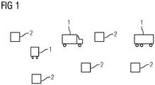
- a vehicle system consists of a number of road vehicles 1 and a number of charging stations 2. Both the number of road vehicles 1 and the number of charging stations 2 is in principle arbitrary. Furthermore, the two numbers are independent. It is possible that only a single road vehicle 1, a few road vehicles 1 or many road vehicles 1 belong to the system. In an analogous manner, the number of charging stations 2 can also vary.
- the road vehicles 1 are preferably commercial vehicles, such as trucks, vans, buses and the like.
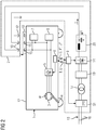
- the road vehicle 1 is battery-powered. It therefore points - see the FIG. 2 and 3 - At least one electric machine 3, which acts in a driving operation of the road vehicle 1 on a drive axle 4 of the road vehicle 1.
- the electric machine 3 has a winding W at least in the stator.
- the winding W is usually formed multi-phase, for example, three-phase.
- the electric machine 3 is in driving operation of the road vehicle 1 by means of a Tratechnischsstromrichters 5 fed from an electrical energy storage 6 of the road vehicle 1.
- electrically operated devices 7 are present, such as auxiliary drives, lighting and the like.
- the other electrically operated devices 7 are of minor importance in the context of the present invention and are therefore not explained in detail.
- the electrical energy storage 6 can in principle be of any desired design, for example as lead-acid battery, as Li-ion storage, as Li-metal hydride storage and the like. An embodiment based on capacitive charge storage is also conceivable. Regardless of its specific embodiment, however, the electrical energy store 6 has a limited capacity. It therefore has to be loaded from time to time.
- the road vehicle 1 drives to one of the charging stations 2.
- the FIGS. 2 to 7 show the road vehicle 1 and the relevant charging station 2. The following statements relate, unless expressly stated otherwise, always to this state in which the road vehicle 1 has the respective charging station 2 approached.
- the control device 9 of the charging station 2 sets contact elements 10 of the charging station 2 under voltage. For example, the control device 9 of the charging station 2 for this purpose to control a contactor S1 accordingly.
- the contact elements 10 of the charging station 2 and a contact arrangement 11 of the road vehicle 1 are brought into contact with each other under the control of a control device 8 of the road vehicle 1.
- the contact elements 10 are arranged above the road vehicle 1.
- the contact arrangement 11 is arranged on an upper side 12 of the road vehicle 1 on the road vehicle 1. Due to the control by the control device 8 of the road vehicle 1, for example, the contact assembly 11 - see in the FIG. 2 and 3 a corresponding arrow - are moved up to the contact elements 10.
- the contact elements 10 are accessible from below in this case. However, other embodiments are possible. For example, in a kinematic reversal, the contact elements 10 - with or without positioning in the horizontal direction - are lowered onto the contact arrangement 11.
- a charging current I from an AC voltage network 13 via the contact elements 10 of the charging station 2, the contact arrangement 11 of the road vehicle 1 and a Charging converter 14 is fed into the electrical energy storage 6 of the road vehicle 1.
- the electric energy storage 6 is thereby charged.
- the charging current converter 14 sets an output voltage U delivered by the charging current converter 14 and / or the charging current I as a function of desired values U * and / or I *.
- the setpoint values U * and / or I * are predetermined by the control device 8 of the road vehicle 1.
- the control device 8 comprises for this purpose, that is, for meaningful specification of the desired values U * and / or I *, including the battery management system of the electric energy storage 6.
- the switching between driving and charging operation for example, with the raising and lowering of the contact assembly 11 (or more generally with the bringing together of the contact elements 10 and the contact assembly 11 and their Separation from each other) be positively coupled.
- the charging operation and the driving operation of the road vehicle 1 may be locked against each other. In this case, it is only possible to switch over from the driving mode to the loading mode and vice versa when the road vehicle 1 is stationary.
- the driving operation may also be possible, while the contact elements 10 and the contact arrangement 11 are in contact with each other. In this case, the road vehicle 1 can also be moved during the charging process.
- the charging power converter 14 is arranged in the charging station 2.
- the control device 8 of the road vehicle 1 first transmits its predetermined values U *, I * to the control device 9 of the charging station 2.
- the control device 9 of the charging station 2 receives the setpoint values U *, I * and then controls the charging current converter 14 If the output voltage U and / or the charge current I are detected on the side of the charging station 2, the control device 9 of the charging station 2 preferably also transmits the detected values U, I to the control device 8 of the road vehicle 1 will be part of the design of the FIG. 2 .
- the charging current I via the contact elements 10 and the contact arrangement 11 is guided both from the charging station 2 to the road vehicle 1 and from the road vehicle 1 to the charging station 2.
- the charging station 2 thus has at least one own contact element 10 for both current directions.
- the contact arrangement 11 also has at least one own contact 15 for both current directions.
- a protective contact element 10 ' is also provided which is connected to a protective contact 15' of the contact arrangement 11.
- the road vehicle 1 is connected to a protection potential, usually earth.
- the charging power converter 14 is initially operated with a charging current I of 0.
- the output voltage U of the charging current converter 14 is therefore preferably also 0 at this time. Only after contacting the contact arrangement 11 and the contact elements 10 does the control device 8 of the road vehicle 1 transmit a desired value I * other than 0 for the charging current I to the control device 9 of the charging station second
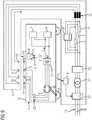
- the charging power converter 14 is arranged in the road vehicle 1.
- the control device 8 of the road vehicle 1 directly controls the charging converter 14.
- the contact arrangement 11 is thus electrically connected to the traction converter 5.
- the contactor S2 is closed by the control device 8 of the road vehicle 1 in the loading operation and otherwise - especially when driving - is opened.
- the contactor S3 is controlled by the control device 8 of the road vehicle 1 complementary to the contactor S2 driven.
- the winding W of the electric machine 3 can be used as the operating inductance of the charging current converter 14.
- contactors S4 and S5 may be present, which are closed by the control device 8 of the road vehicle 1 in the loading operation and opened while driving.
- control device 8 of the road vehicle 1 transmits the switching command S preferably only after contacting the contact arrangement 11 and the contact elements 10 to the control device 9 of the charging station 2.
- the contact elements 10 may be provided with series resistors V, which after contacting the contact assembly 11 and the contact elements 10 - for example by means of a contactor S6 - be bridged.
- the AC voltage network 13 is usually a three-phase network with multiple phases 16, for example, three phases 16.
- each phase 16 each have their own contact element 11 available.
- the contact arrangement 11 preferably has at least one separate contact 15 for each phase 16.
- a protective contact element 10 ' is present, which is connected to a protective contact 15' of the contact arrangement 11.
- the road vehicle 1 is connected to the protection potential.
- the charging station 2 is preferably from the public power grid 13 with supplied electrical energy.
- the nominal voltage of the AC voltage network 13 may be, for example, 3-phase AC voltage of 400 V or 690 V and 50 Hz or 60 Hz. Other voltages are possible. If necessary, a voltage conversion can take place by means of a transformer 17. In particular - but not necessarily - in the design of the FIG. 3 . 6 and 7 a voltage conversion to a three-phase three-phase system with 300 V rated voltage.
- the transformer 17 is always present, so even if a voltage conversion is not required.
- the transformer 17 effects a potential separation of the contact elements 10 of the charging station 2 from the power supply of the charging station 2.
- the transformer 17 if it is present, designed as a three-phase transformer. Also in the embodiment according to FIG. 2 is the transformer 17, if it is present, designed as a three-phase transformer.
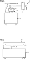
- both in the embodiment of FIG. 2 . 4 and 5 as well as in the design of the FIG. 3 . 6 and 7 - Are the contact elements 10, 10 'according to the FIG. 5 and 7 preferably formed as elongated, mutually parallel contact elements 10, 10 '.
- the contact elements 10, 10 ' for example, at the same height next to each other, be arranged at the same height one behind the other or one above the other.
- the charging station 2 further preferably on a roof 18, by means of which the contact elements 10, 10 ' are covered. It is possible that the contact elements 10, 10 'are integrated into the roof 18.
- the present invention may be further supplemented in various respects.
- FIG. 2 and 3 Be the charging power converter 14 upstream of a filter 19. Furthermore - see FIG. 2 - Be the charging station 14, a filter 20 downstream.
- the filter 20 can also in the embodiment according to FIG. 3 to be available. It is there only for the sake of clarity not shown.
- the charging power converter 14 is connected directly or via the filter 20 with the contact elements 10.
- the charging power converter 14 is arranged in front of the transformer 17 and the output voltage of the transformer 17 is rectified by means of a rectifier 21.
- the transformer 17 may be formed as a single-phase transformer.
- the rectifier 21 may alternatively be designed as a controlled rectifier or as a diode rectifier.
- the winding W in the charging mode between the traction converter 5 and the electrical energy storage 6 connected is the winding W in the charging mode between the traction converter 5 and the electrical energy storage 6 connected.
- no inductances are connected between the contacts 15 of the contact arrangement 11 and the traction converter 5.
- the contact elements 10 chokes 22 upstream.
- FIG. 9 shows a modification of the embodiment of FIG. 3 .
- the embodiment according to FIG. 9 corresponds largely to the design of FIG. 3 , Below, therefore, only the differences are discussed in more detail.
- FIG. 9 is the winding W (or their individual winding strands) connected in the charging mode between the contacts 15 and the traction converter 5.
- a suitable, known per se division of the winding W can be ensured that despite the current flow through the winding W no torque acts on the drive shaft 4.
- a mechanical brake can prevent movement of the road vehicle 1.
- the contact elements 10 upstream chokes are not required. They may, however, be present.
- the road vehicles 1 and with respect to the charging stations 2 it is possible to design them in a multi-system manner.
- the road vehicle 1 depending on the configuration of the charging station 2 alternatively as shown in FIG FIG. 2 or 8th or as shown in FIG. 3 or 9 configure.
- the charging station 2 depending on the design of the road vehicle 1 alternatively as shown in FIG. 2 and 8th via two contact elements 10, a direct current or as shown in FIG FIG. 3 and 9 via three contact elements 10 outputs a three-phase current to the road vehicle 1.
- an automated detection of the road vehicle 1 is carried out, so that an automated billing can be done.
- the charging station 2 can be formed very space-saving. All the other components - for example the contactor S1, the transformer 17, the filter 19 and, if present on the side of the charging station 2, the charging converter 14 and the filter are the only elements which must be arranged above the roadway 20 - may be arranged above ground or underground as required.
- the present invention has many advantages. Some of these benefits are listed below.
- the charging stations 2 can be constructed without having to additionally build an infrastructure beyond the charging stations 2 as such. Because the only required system requirement is the public power grid 13, which is present anyway in cities. Furthermore, the charging stations 2 can coincide, for example, with the end stops of bus lines. Since in particular omnibuses (city buses) often pause for several minutes at the terminal stops, this break can readily be used at the same time for loading the road vehicle 1. Furthermore, all the heavy components required for the charging process can be arranged outside the road vehicle 1. Furthermore, these components do not have to be geared to the increased demands that usually prevail on road vehicle 1. For example, protection against shock, vibration and the like is no longer required.
Landscapes
- Engineering & Computer Science (AREA)
- Power Engineering (AREA)
- Transportation (AREA)
- Mechanical Engineering (AREA)
- Life Sciences & Earth Sciences (AREA)
- Sustainable Development (AREA)
- Sustainable Energy (AREA)
- Charge And Discharge Circuits For Batteries Or The Like (AREA)
- Electric Propulsion And Braking For Vehicles (AREA)
Priority Applications (1)
| Application Number | Priority Date | Filing Date | Title |
|---|---|---|---|
| PL14755051T PL3003774T3 (pl) | 2013-08-22 | 2014-08-18 | Ładowanie pojazdu drogowego zasilanego akumulatorem |
Applications Claiming Priority (2)
| Application Number | Priority Date | Filing Date | Title |
|---|---|---|---|
| DE102013216700.8A DE102013216700B4 (de) | 2013-08-22 | 2013-08-22 | Ladung von batteriefahrtfähigen Straßenfahrzeugen |
| PCT/EP2014/067561 WO2015024900A2 (de) | 2013-08-22 | 2014-08-18 | Ladung von batteriefahrtfähigen strassenfahrzeugen |
Publications (2)
| Publication Number | Publication Date |
|---|---|
| EP3003774A2 EP3003774A2 (de) | 2016-04-13 |
| EP3003774B1 true EP3003774B1 (de) | 2017-08-02 |
Family
ID=51392240
Family Applications (1)
| Application Number | Title | Priority Date | Filing Date |
|---|---|---|---|
| EP14755051.1A Not-in-force EP3003774B1 (de) | 2013-08-22 | 2014-08-18 | Ladung von batteriefahrtfähigen strassenfahrzeugen |
Country Status (8)
| Country | Link |
|---|---|
| US (1) | US20160200205A1 (pl) |
| EP (1) | EP3003774B1 (pl) |
| CN (1) | CN105473374B (pl) |
| DE (1) | DE102013216700B4 (pl) |
| ES (1) | ES2645838T3 (pl) |
| PL (1) | PL3003774T3 (pl) |
| RU (1) | RU2633423C2 (pl) |
| WO (1) | WO2015024900A2 (pl) |
Families Citing this family (17)
| Publication number | Priority date | Publication date | Assignee | Title |
|---|---|---|---|---|
| DE102014217219A1 (de) * | 2014-08-28 | 2016-03-03 | Siemens Aktiengesellschaft | Elektrische Schaltung für ein Fahrzeug und Verfahren zur Kontaktaufnahme und/oder -beendigung eines Fahrzeugs mit einem fahrzeugexternen elektrischen Netz |
| FR3060230B1 (fr) * | 2016-12-14 | 2019-01-25 | Renault S.A.S | Procede de commande d'un dispositif de charge embarque sur un vehicule electrique ou hybride. |
| WO2018137047A1 (en) | 2017-01-30 | 2018-08-02 | Clearpath Robotics, Inc. | Apparatus, systems, and methods for operating and maintaining electrically-powered material-transport vehicles |
| DE102017103032A1 (de) * | 2017-02-15 | 2018-08-16 | Konecranes Global Corporation | Stromtankstelle für ein containertransportfahrzeug, containertransportfahrzeug und system hiermit |
| US11541768B2 (en) | 2017-02-15 | 2023-01-03 | Volvo Truck Corporation | Arrangement and method for active alignment control of a contact element |
| CN107757413A (zh) * | 2017-11-13 | 2018-03-06 | 河南森源电气股份有限公司 | 一种电动汽车运动式充电站 |
| DE102018212053B4 (de) * | 2018-07-19 | 2020-07-09 | Siemens Mobility GmbH | Verfahren und Vorrichtungen zum Laden zumindest eines Energiespeichers eines Schienenfahrzeugs |
| IT201800007391A1 (it) * | 2018-07-20 | 2020-01-20 | Caricabatterie per autoveicoli elettrici o ibridi | |
| CN109050544B (zh) * | 2018-09-27 | 2023-09-01 | 中车戚墅堰机车有限公司 | 一种有轨电车用纯锂电池驱动牵引系统 |
| RU2726352C1 (ru) * | 2019-02-18 | 2020-07-13 | Дмитрий Александрович Полетаев | Система электрического привода |
| CN110103728A (zh) * | 2019-05-10 | 2019-08-09 | 吉林大学青岛汽车研究院 | 一种基于在线直流驱动的长途重载运输系统 |
| DE102019006065A1 (de) * | 2019-08-28 | 2021-03-04 | Kostal Automobil Elektrik Gmbh & Co. Kg | Ladesystem zum Gleichstromladen der Traktionsbatterie eines elektrisch angetriebenen Kraftfahrzeugs |
| CN112550063B (zh) * | 2019-09-25 | 2021-12-07 | 比亚迪股份有限公司 | 能量转换装置、车辆、协同控制方法及装置、存储介质 |
| DE102019214938A1 (de) * | 2019-09-27 | 2021-04-01 | Siemens Mobility GmbH | Ladesystem zum Aufladen eines elektrischen Energiespeichers eines Straßenfahrzeugs |
| RU201100U1 (ru) * | 2020-02-26 | 2020-11-26 | Общество с ограниченной ответственностью "РД-ХЕЛИ" | Мобильная зарядная станция постоянного тока для быстрого заряда электрических транспортных средств |
| BE1028464B1 (de) * | 2020-07-09 | 2022-02-08 | Phoenix Contact Gmbh & Co | Technik zur Überwachung eines Kontakts zwischen Ladeleitern zum Laden eines Elektrofahrzeugs |
| RU203237U1 (ru) * | 2020-10-14 | 2021-03-29 | Федеральное Государственное Бюджетное Образовательное Учреждение Высшего Образования «Новосибирский Государственный Технический Университет» | Устройство зарядной станции постоянным током на базе тяговой подстанции электрического транспорта |
Family Cites Families (47)
| Publication number | Priority date | Publication date | Assignee | Title |
|---|---|---|---|---|
| US3955657A (en) * | 1974-02-15 | 1976-05-11 | Oscar Bossi | Electric traction transportation system with storage battery powered vehicles and fast recharge at the vehicle stops |
| DE2330255A1 (de) * | 1973-06-14 | 1975-01-16 | Elektr Strassenverkehr Ges | Verfahren und anlage zum betrieb von kraftfahrzeugen mit elektrisch aufladbarem energiespeicher |
| GB1513256A (en) * | 1974-07-16 | 1978-06-07 | Thomson Csf | Electrical machine |
| JPS53103116A (en) * | 1977-02-18 | 1978-09-08 | Mitsubishi Electric Corp | Induction motor controller |
| US4210826A (en) * | 1978-09-21 | 1980-07-01 | Exxon Research & Engineering Co. | Switching circuit |
| US4237410A (en) * | 1978-10-23 | 1980-12-02 | Erickson Alfred C | Regenerative electric motor |
| AT370043B (de) | 1980-01-22 | 1983-02-25 | Siemens Ag Oesterreich | Stromversorgungseinrichtung fuer elektrofahrzeuge |
| US4883973A (en) * | 1988-08-01 | 1989-11-28 | General Motors Corporation | Automotive electrical system having a starter/generator induction machine |
| AT398555B (de) | 1991-05-31 | 1994-12-27 | Steyr Daimler Puch Ag | Regelschaltung für batteriebetriebene elektrofahrzeuge |
| JPH07193910A (ja) * | 1993-04-09 | 1995-07-28 | Hitachi Ltd | 電気自動車の制御装置 |
| EP0622264B1 (en) * | 1993-04-28 | 1998-11-11 | Hitachi, Ltd. | Electric vehicle drive system and drive method |
| DE19516838A1 (de) * | 1995-05-08 | 1996-11-14 | Hagen Batterie Ag | Verfahren und Schaltungsanordnung zur Deckung von Energiespitzenbedarf bei elektrischen Wechselstrom- bzw. Drehstromnetzen |
| US5640071A (en) * | 1995-10-10 | 1997-06-17 | Malaspina; Francis P. | Transient charge recovery circuit |
| CH689748A5 (de) | 1995-10-13 | 1999-09-30 | Asmo Engineering | Vorrichtung zum Laden von Batterien von Elektrofahrzeugen. |
| ES2207684T3 (es) * | 1995-10-24 | 2004-06-01 | Aquagas New Zealand Limited | Convertidor de corriente alterna en corriente continua. |
| US6118203A (en) * | 1999-06-03 | 2000-09-12 | General Electric Company | High efficiency motor for x-ray generation |
| JP2001128304A (ja) * | 1999-10-27 | 2001-05-11 | Toshiba Corp | 電気自動車の走行充電システム |
| US6919711B2 (en) * | 2001-09-19 | 2005-07-19 | Newage International Limited | Electrical machine and an electrical power generating system |
| US6572416B2 (en) * | 2001-11-05 | 2003-06-03 | Ballard Power Systems Corporation | Three-phase connector for electric vehicle drivetrain |
| JP2004245073A (ja) * | 2003-02-12 | 2004-09-02 | Matsushita Electric Ind Co Ltd | 電動圧縮機 |
| KR100527463B1 (ko) * | 2003-06-16 | 2005-11-09 | 현대자동차주식회사 | 3상 유도 전동기 접속 장치 |
| JP4682740B2 (ja) * | 2005-08-08 | 2011-05-11 | トヨタ自動車株式会社 | 車両の電源装置 |
| JP4339832B2 (ja) * | 2005-08-11 | 2009-10-07 | 三菱電機株式会社 | 車両用回転電機 |
| FR2892069B1 (fr) * | 2005-10-17 | 2014-07-18 | Pvi | Poste de recharge et vehicule electrique associe |
| US7459889B2 (en) * | 2007-01-09 | 2008-12-02 | Honeywell International, Inc. | DC bus short circuit compliant power generation systems using induction machine |
| KR100999969B1 (ko) * | 2007-12-12 | 2010-12-09 | 현대자동차주식회사 | 배터리 충전 장치 |
| US7692908B2 (en) * | 2008-01-02 | 2010-04-06 | Glj, Llc | Protection of polarity-sensitive components connected in parallel with a direct current motor or inductor |
| US7999403B2 (en) * | 2008-06-24 | 2011-08-16 | General Electric Company | System and method for locomotive engine cranking |
| EP2296933B1 (en) * | 2008-07-01 | 2016-10-05 | Proterra Inc. | Charging stations for electric vehicles |
| FR2938711B1 (fr) * | 2008-11-18 | 2012-12-14 | Valeo Sys Controle Moteur Sas | Dispositif electrique combine d'alimentation et de charge |
| DE102009007960A1 (de) * | 2009-02-06 | 2010-08-19 | Sew-Eurodrive Gmbh & Co. Kg | Antriebssystem, Verfahren zum Betreiben eines Antriebssystems und Verwendung |
| DE102009048666B4 (de) * | 2009-09-29 | 2015-08-20 | Siemens Aktiengesellschaft | Schienenfahrzeug |
| CN102917907A (zh) | 2009-12-23 | 2013-02-06 | 普罗特拉公司 | 用于电动车辆的充电站 |
| CN103038975B (zh) * | 2010-04-26 | 2016-09-14 | 普罗特拉公司 | 用于电动车在充电站自动连接和充电的系统与方法 |
| FR2961965B1 (fr) * | 2010-06-25 | 2012-07-13 | Valeo Sys Controle Moteur Sas | Dispositif de charge de moyens d'accumulation |
| WO2012014324A1 (ja) | 2010-07-30 | 2012-02-02 | 三菱電機株式会社 | 電気車の推進制御装置、および鉄道車両システム |
| US8432126B2 (en) * | 2010-09-09 | 2013-04-30 | GM Global Technology Operations LLC | Rapid offboard charging via selective energizing of designated semiconductor switches and induction coils in an electric or hybrid electric vehicle |
| DE102010040972B4 (de) * | 2010-09-17 | 2018-12-06 | Siemens Aktiengesellschaft | Betriebsaufbau für ein elektrisch betriebenes Fahrzeug |
| US20120153884A1 (en) * | 2010-12-21 | 2012-06-21 | Caterpillar Inc. | Integrated motor controller system |
| BRPI1102466A2 (pt) * | 2011-05-26 | 2013-06-25 | Whirlpool Sa | mÉtodo e sistema de controle de tensço de entrada em cargas elÉtricas |
| US20130001944A1 (en) * | 2011-06-30 | 2013-01-03 | Hickam Christopher D | Starting method/apparatus for series electric drive |
| FR2982092B1 (fr) * | 2011-11-02 | 2015-01-02 | Valeo Systemes De Controle Moteur | Module de puissance et dispositif electrique pour l'alimentation et la charge combinees respectivement d'un accumulateur et d'un moteur |
| WO2013158083A1 (en) * | 2012-04-18 | 2013-10-24 | International Engine Intellectual Property Company, Llc | Hybrid drive train control method |
| FR3004596A1 (fr) * | 2013-04-11 | 2014-10-17 | Schneider Electric Ind Sas | Procede de charge par induction d'une batterie de vehicule |
| US9914362B2 (en) * | 2013-04-15 | 2018-03-13 | Virginia Tech Intellectual Properties, Inc. | Energy storage for power factor correction in battery charger for electric-powered vehicles |
| DE102013209706B3 (de) * | 2013-05-24 | 2014-11-20 | Siemens Aktiengesellschaft | Kühlanlage zur Kühlung eines Energiespeichers und eines Ladereglers für ein Fahrzeug mit elektrischem Antrieb |
| JP6146396B2 (ja) * | 2014-11-14 | 2017-06-14 | トヨタ自動車株式会社 | 電動モーターによって駆動する車両、および、その車両の制御方法 |
-
2013
- 2013-08-22 DE DE102013216700.8A patent/DE102013216700B4/de not_active Expired - Fee Related
-
2014
- 2014-08-18 EP EP14755051.1A patent/EP3003774B1/de not_active Not-in-force
- 2014-08-18 ES ES14755051.1T patent/ES2645838T3/es active Active
- 2014-08-18 US US14/913,270 patent/US20160200205A1/en not_active Abandoned
- 2014-08-18 RU RU2016110091A patent/RU2633423C2/ru active
- 2014-08-18 CN CN201480046227.8A patent/CN105473374B/zh not_active Expired - Fee Related
- 2014-08-18 WO PCT/EP2014/067561 patent/WO2015024900A2/de not_active Ceased
- 2014-08-18 PL PL14755051T patent/PL3003774T3/pl unknown
Also Published As
| Publication number | Publication date |
|---|---|
| EP3003774A2 (de) | 2016-04-13 |
| CN105473374A (zh) | 2016-04-06 |
| RU2633423C2 (ru) | 2017-10-12 |
| ES2645838T3 (es) | 2017-12-11 |
| DE102013216700B4 (de) | 2022-01-27 |
| CN105473374B (zh) | 2018-04-27 |
| US20160200205A1 (en) | 2016-07-14 |
| DE102013216700A1 (de) | 2015-02-26 |
| RU2016110091A (ru) | 2017-09-27 |
| WO2015024900A2 (de) | 2015-02-26 |
| PL3003774T3 (pl) | 2017-12-29 |
| WO2015024900A3 (de) | 2015-05-28 |
Similar Documents
| Publication | Publication Date | Title |
|---|---|---|
| EP3003774B1 (de) | Ladung von batteriefahrtfähigen strassenfahrzeugen | |
| DE102017207102A1 (de) | Stationärspeicher zum Zwischenspeichern von elektrischer Energie in einem elektrischen Versorgungsnetz sowie Betriebsverfahren und Nachrüstmodul für den Stationärspeicher | |
| DE102015215178A1 (de) | Vorrichtung und ein Verfahren zum oberleitungslosen Betreiben eines Schienenfahrzeugs | |
| EP3019366A2 (de) | Mehrsystem-stromrichteranordnung | |
| EP3597469B1 (de) | Verfahren und vorrichtungen zum laden zumindest eines energiespeichers eines schienenfahrzeugs | |
| DE102015215174A1 (de) | Vorrichtung und ein Verfahren zum oberleitungslosen Betreiben eines Schienenfahrzeugs | |
| DE102012202955A1 (de) | Stromübertragungsvorrichtung zur Aufladung elektrischer Energiespeicher von Fahrzeugen an Überkopfladestationen | |
| AT500328B1 (de) | Fahrzeug mit einem elektrischen antrieb und verfahren zum betrieb eines solchen fahrzeuges | |
| DE102013201491A1 (de) | Vorrichtung zum Übertragen elektrischer Energie an ein Fahrzeug | |
| DE102020200300A1 (de) | Verfahren zum Betrieb eines elektrisch angetriebenen oder antreibbaren Kraftfahrzeugs | |
| DE102012007158A1 (de) | Pulswechselrichter mit Stromzwischenkreis zum Fahren und Laden eines batteriebetriebenen Elektrofahrzeugs | |
| WO2022219024A1 (de) | Verfahren zum durchführen eines vorladevorgangs eines elektrischen bordnetzes eines fahrzeugs und elektrisches bordnetz für ein fahrzeug | |
| EP2259949B1 (de) | Energiespeichersystem für ein spurgeführtes fahrzeug | |
| DE102016002459A1 (de) | Elektrische Anlage für ein elektrisch antreibbares Kraftfahrzeug | |
| DE102018202260A1 (de) | Ladefahrzeug zum Laden eines elektrischen Energiespeichers eines Elektrofahrzeugs | |
| EP3142890B1 (de) | Hochspannungseinrichtung für ein schienenfahrzeug | |
| EP3541652B1 (de) | Elektrisches netzwerk für ein schienenfahrzeug, schienenfahrzeug und verfahren zum betrieb eines elektrischen netzwerks | |
| EP3027462A1 (de) | Energiespeicheranordnung, energiespeichersystem und verfahren für das betreiben einer energiespeicheranordnung | |
| WO2014029582A1 (de) | Fahrzeug für den streckennetz- und den batteriebetrieb | |
| WO2024146716A1 (de) | Stromversorgung für ein schienenfahrzeug mit traktionsbatterie | |
| EP3818210A1 (de) | Schienenfahrzeug | |
| DE202017104077U1 (de) | Energieverteilungsanordnung und Ladestation für ein Elektromobil | |
| EP3798042B1 (de) | Batteriegestütztes schienenfahrzeug | |
| WO2020254470A1 (de) | Schaltungsanordnung für ein kraftfahrzeug und verfahren zum anpassen einer spannung eines hochvolt-gleichspannungszwischenkreises in einem kraftfahrzeug | |
| DE202014002840U1 (de) | Elektrisches Automobil |
Legal Events
| Date | Code | Title | Description |
|---|---|---|---|
| PUAI | Public reference made under article 153(3) epc to a published international application that has entered the european phase |
Free format text: ORIGINAL CODE: 0009012 |
|
| 17P | Request for examination filed |
Effective date: 20160107 |
|
| AK | Designated contracting states |
Kind code of ref document: A2 Designated state(s): AL AT BE BG CH CY CZ DE DK EE ES FI FR GB GR HR HU IE IS IT LI LT LU LV MC MK MT NL NO PL PT RO RS SE SI SK SM TR |
|
| AX | Request for extension of the european patent |
Extension state: BA ME |
|
| DAX | Request for extension of the european patent (deleted) | ||
| GRAP | Despatch of communication of intention to grant a patent |
Free format text: ORIGINAL CODE: EPIDOSNIGR1 |
|
| INTG | Intention to grant announced |
Effective date: 20170221 |
|
| GRAS | Grant fee paid |
Free format text: ORIGINAL CODE: EPIDOSNIGR3 |
|
| GRAA | (expected) grant |
Free format text: ORIGINAL CODE: 0009210 |
|
| AK | Designated contracting states |
Kind code of ref document: B1 Designated state(s): AL AT BE BG CH CY CZ DE DK EE ES FI FR GB GR HR HU IE IS IT LI LT LU LV MC MK MT NL NO PL PT RO RS SE SI SK SM TR |
|
| REG | Reference to a national code |
Ref country code: FR Ref legal event code: PLFP Year of fee payment: 4 |
|
| REG | Reference to a national code |
Ref country code: AT Ref legal event code: REF Ref document number: 914057 Country of ref document: AT Kind code of ref document: T Effective date: 20170815 Ref country code: CH Ref legal event code: EP |
|
| REG | Reference to a national code |
Ref country code: IE Ref legal event code: FG4D Free format text: LANGUAGE OF EP DOCUMENT: GERMAN |
|
| RAP2 | Party data changed (patent owner data changed or rights of a patent transferred) |
Owner name: SIEMENS AKTIENGESELLSCHAFT |
|
| REG | Reference to a national code |
Ref country code: DE Ref legal event code: R096 Ref document number: 502014004832 Country of ref document: DE |
|
| REG | Reference to a national code |
Ref country code: CH Ref legal event code: PCOW Ref country code: CH Ref legal event code: NV Representative=s name: SIEMENS SCHWEIZ AG, CH |
|
| REG | Reference to a national code |
Ref country code: SE Ref legal event code: TRGR |
|
| REG | Reference to a national code |
Ref country code: NL Ref legal event code: FP |
|
| REG | Reference to a national code |
Ref country code: ES Ref legal event code: FG2A Ref document number: 2645838 Country of ref document: ES Kind code of ref document: T3 Effective date: 20171211 |
|
| REG | Reference to a national code |
Ref country code: LT Ref legal event code: MG4D |
|
| PG25 | Lapsed in a contracting state [announced via postgrant information from national office to epo] |
Ref country code: FI Free format text: LAPSE BECAUSE OF FAILURE TO SUBMIT A TRANSLATION OF THE DESCRIPTION OR TO PAY THE FEE WITHIN THE PRESCRIBED TIME-LIMIT Effective date: 20170802 Ref country code: HR Free format text: LAPSE BECAUSE OF FAILURE TO SUBMIT A TRANSLATION OF THE DESCRIPTION OR TO PAY THE FEE WITHIN THE PRESCRIBED TIME-LIMIT Effective date: 20170802 Ref country code: LT Free format text: LAPSE BECAUSE OF FAILURE TO SUBMIT A TRANSLATION OF THE DESCRIPTION OR TO PAY THE FEE WITHIN THE PRESCRIBED TIME-LIMIT Effective date: 20170802 Ref country code: NO Free format text: LAPSE BECAUSE OF FAILURE TO SUBMIT A TRANSLATION OF THE DESCRIPTION OR TO PAY THE FEE WITHIN THE PRESCRIBED TIME-LIMIT Effective date: 20171102 |
|
| PG25 | Lapsed in a contracting state [announced via postgrant information from national office to epo] |
Ref country code: IS Free format text: LAPSE BECAUSE OF FAILURE TO SUBMIT A TRANSLATION OF THE DESCRIPTION OR TO PAY THE FEE WITHIN THE PRESCRIBED TIME-LIMIT Effective date: 20171202 Ref country code: RS Free format text: LAPSE BECAUSE OF FAILURE TO SUBMIT A TRANSLATION OF THE DESCRIPTION OR TO PAY THE FEE WITHIN THE PRESCRIBED TIME-LIMIT Effective date: 20170802 Ref country code: GR Free format text: LAPSE BECAUSE OF FAILURE TO SUBMIT A TRANSLATION OF THE DESCRIPTION OR TO PAY THE FEE WITHIN THE PRESCRIBED TIME-LIMIT Effective date: 20171103 Ref country code: LV Free format text: LAPSE BECAUSE OF FAILURE TO SUBMIT A TRANSLATION OF THE DESCRIPTION OR TO PAY THE FEE WITHIN THE PRESCRIBED TIME-LIMIT Effective date: 20170802 Ref country code: BG Free format text: LAPSE BECAUSE OF FAILURE TO SUBMIT A TRANSLATION OF THE DESCRIPTION OR TO PAY THE FEE WITHIN THE PRESCRIBED TIME-LIMIT Effective date: 20171102 |
|
| REG | Reference to a national code |
Ref country code: CH Ref legal event code: PL |
|
| PG25 | Lapsed in a contracting state [announced via postgrant information from national office to epo] |
Ref country code: RO Free format text: LAPSE BECAUSE OF FAILURE TO SUBMIT A TRANSLATION OF THE DESCRIPTION OR TO PAY THE FEE WITHIN THE PRESCRIBED TIME-LIMIT Effective date: 20170802 Ref country code: CZ Free format text: LAPSE BECAUSE OF FAILURE TO SUBMIT A TRANSLATION OF THE DESCRIPTION OR TO PAY THE FEE WITHIN THE PRESCRIBED TIME-LIMIT Effective date: 20170802 Ref country code: LI Free format text: LAPSE BECAUSE OF NON-PAYMENT OF DUE FEES Effective date: 20170831 Ref country code: DK Free format text: LAPSE BECAUSE OF FAILURE TO SUBMIT A TRANSLATION OF THE DESCRIPTION OR TO PAY THE FEE WITHIN THE PRESCRIBED TIME-LIMIT Effective date: 20170802 Ref country code: CH Free format text: LAPSE BECAUSE OF NON-PAYMENT OF DUE FEES Effective date: 20170831 |
|
| REG | Reference to a national code |
Ref country code: DE Ref legal event code: R097 Ref document number: 502014004832 Country of ref document: DE |
|
| REG | Reference to a national code |
Ref country code: IE Ref legal event code: MM4A |
|
| PG25 | Lapsed in a contracting state [announced via postgrant information from national office to epo] |
Ref country code: MC Free format text: LAPSE BECAUSE OF FAILURE TO SUBMIT A TRANSLATION OF THE DESCRIPTION OR TO PAY THE FEE WITHIN THE PRESCRIBED TIME-LIMIT Effective date: 20170802 Ref country code: SM Free format text: LAPSE BECAUSE OF FAILURE TO SUBMIT A TRANSLATION OF THE DESCRIPTION OR TO PAY THE FEE WITHIN THE PRESCRIBED TIME-LIMIT Effective date: 20170802 Ref country code: SK Free format text: LAPSE BECAUSE OF FAILURE TO SUBMIT A TRANSLATION OF THE DESCRIPTION OR TO PAY THE FEE WITHIN THE PRESCRIBED TIME-LIMIT Effective date: 20170802 Ref country code: EE Free format text: LAPSE BECAUSE OF FAILURE TO SUBMIT A TRANSLATION OF THE DESCRIPTION OR TO PAY THE FEE WITHIN THE PRESCRIBED TIME-LIMIT Effective date: 20170802 |
|
| PLBE | No opposition filed within time limit |
Free format text: ORIGINAL CODE: 0009261 |
|
| STAA | Information on the status of an ep patent application or granted ep patent |
Free format text: STATUS: NO OPPOSITION FILED WITHIN TIME LIMIT |
|
| PG25 | Lapsed in a contracting state [announced via postgrant information from national office to epo] |
Ref country code: LU Free format text: LAPSE BECAUSE OF NON-PAYMENT OF DUE FEES Effective date: 20170818 |
|
| 26N | No opposition filed |
Effective date: 20180503 |
|
| PG25 | Lapsed in a contracting state [announced via postgrant information from national office to epo] |
Ref country code: IE Free format text: LAPSE BECAUSE OF NON-PAYMENT OF DUE FEES Effective date: 20170818 |
|
| REG | Reference to a national code |
Ref country code: FR Ref legal event code: PLFP Year of fee payment: 5 |
|
| PG25 | Lapsed in a contracting state [announced via postgrant information from national office to epo] |
Ref country code: SI Free format text: LAPSE BECAUSE OF FAILURE TO SUBMIT A TRANSLATION OF THE DESCRIPTION OR TO PAY THE FEE WITHIN THE PRESCRIBED TIME-LIMIT Effective date: 20170802 |
|
| PG25 | Lapsed in a contracting state [announced via postgrant information from national office to epo] |
Ref country code: MT Free format text: LAPSE BECAUSE OF FAILURE TO SUBMIT A TRANSLATION OF THE DESCRIPTION OR TO PAY THE FEE WITHIN THE PRESCRIBED TIME-LIMIT Effective date: 20170802 |
|
| REG | Reference to a national code |
Ref country code: DE Ref legal event code: R079 Ref document number: 502014004832 Country of ref document: DE Free format text: PREVIOUS MAIN CLASS: B60L0011180000 Ipc: B60L0050500000 |
|
| REG | Reference to a national code |
Ref country code: DE Ref legal event code: R081 Ref document number: 502014004832 Country of ref document: DE Owner name: SIEMENS MOBILITY GMBH, DE Free format text: FORMER OWNER: SIEMENS AKTIENGESELLSCHAFT, 80333 MUENCHEN, DE |
|
| REG | Reference to a national code |
Ref country code: GB Ref legal event code: 732E Free format text: REGISTERED BETWEEN 20190207 AND 20190213 |
|
| REG | Reference to a national code |
Ref country code: AT Ref legal event code: PC Ref document number: 914057 Country of ref document: AT Kind code of ref document: T Owner name: SIEMENS MOBILITY GMBH, DE Effective date: 20190506 |
|
| PG25 | Lapsed in a contracting state [announced via postgrant information from national office to epo] |
Ref country code: HU Free format text: LAPSE BECAUSE OF FAILURE TO SUBMIT A TRANSLATION OF THE DESCRIPTION OR TO PAY THE FEE WITHIN THE PRESCRIBED TIME-LIMIT; INVALID AB INITIO Effective date: 20140818 |
|
| REG | Reference to a national code |
Ref country code: NL Ref legal event code: PD Owner name: SIEMENS MOBILITY GMBH; DE Free format text: DETAILS ASSIGNMENT: CHANGE OF OWNER(S), ASSIGNMENT; FORMER OWNER NAME: SIEMENS AKTIENGESELLSCHAFT Effective date: 20190829 |
|
| PG25 | Lapsed in a contracting state [announced via postgrant information from national office to epo] |
Ref country code: CY Free format text: LAPSE BECAUSE OF FAILURE TO SUBMIT A TRANSLATION OF THE DESCRIPTION OR TO PAY THE FEE WITHIN THE PRESCRIBED TIME-LIMIT Effective date: 20170802 |
|
| PG25 | Lapsed in a contracting state [announced via postgrant information from national office to epo] |
Ref country code: MK Free format text: LAPSE BECAUSE OF FAILURE TO SUBMIT A TRANSLATION OF THE DESCRIPTION OR TO PAY THE FEE WITHIN THE PRESCRIBED TIME-LIMIT Effective date: 20170802 |
|
| REG | Reference to a national code |
Ref country code: BE Ref legal event code: PD Owner name: SIEMENS MOBILITY GMBH; DE Free format text: DETAILS ASSIGNMENT: CHANGE OF OWNER(S), CESSION; FORMER OWNER NAME: SIEMENS AKTIENGESELLSCHAFT Effective date: 20190911 |
|
| PG25 | Lapsed in a contracting state [announced via postgrant information from national office to epo] |
Ref country code: TR Free format text: LAPSE BECAUSE OF FAILURE TO SUBMIT A TRANSLATION OF THE DESCRIPTION OR TO PAY THE FEE WITHIN THE PRESCRIBED TIME-LIMIT Effective date: 20170802 |
|
| PG25 | Lapsed in a contracting state [announced via postgrant information from national office to epo] |
Ref country code: PT Free format text: LAPSE BECAUSE OF FAILURE TO SUBMIT A TRANSLATION OF THE DESCRIPTION OR TO PAY THE FEE WITHIN THE PRESCRIBED TIME-LIMIT Effective date: 20170802 |
|
| PG25 | Lapsed in a contracting state [announced via postgrant information from national office to epo] |
Ref country code: AL Free format text: LAPSE BECAUSE OF FAILURE TO SUBMIT A TRANSLATION OF THE DESCRIPTION OR TO PAY THE FEE WITHIN THE PRESCRIBED TIME-LIMIT Effective date: 20170802 |
|
| REG | Reference to a national code |
Ref country code: ES Ref legal event code: PC2A Owner name: SIEMENS MOBILITY GMBH Effective date: 20200805 |
|
| PGFP | Annual fee paid to national office [announced via postgrant information from national office to epo] |
Ref country code: NL Payment date: 20210802 Year of fee payment: 8 |
|
| PGFP | Annual fee paid to national office [announced via postgrant information from national office to epo] |
Ref country code: AT Payment date: 20210708 Year of fee payment: 8 Ref country code: IT Payment date: 20210812 Year of fee payment: 8 Ref country code: FR Payment date: 20210817 Year of fee payment: 8 |
|
| PGFP | Annual fee paid to national office [announced via postgrant information from national office to epo] |
Ref country code: BE Payment date: 20210819 Year of fee payment: 8 Ref country code: PL Payment date: 20210811 Year of fee payment: 8 Ref country code: GB Payment date: 20210908 Year of fee payment: 8 Ref country code: SE Payment date: 20210805 Year of fee payment: 8 |
|
| PGFP | Annual fee paid to national office [announced via postgrant information from national office to epo] |
Ref country code: DE Payment date: 20211019 Year of fee payment: 8 Ref country code: ES Payment date: 20211124 Year of fee payment: 8 |
|
| REG | Reference to a national code |
Ref country code: DE Ref legal event code: R119 Ref document number: 502014004832 Country of ref document: DE |
|
| REG | Reference to a national code |
Ref country code: SE Ref legal event code: EUG |
|
| REG | Reference to a national code |
Ref country code: NL Ref legal event code: MM Effective date: 20220901 |
|
| REG | Reference to a national code |
Ref country code: AT Ref legal event code: MM01 Ref document number: 914057 Country of ref document: AT Kind code of ref document: T Effective date: 20220818 |
|
| GBPC | Gb: european patent ceased through non-payment of renewal fee |
Effective date: 20220818 |
|
| PG25 | Lapsed in a contracting state [announced via postgrant information from national office to epo] |
Ref country code: SE Free format text: LAPSE BECAUSE OF NON-PAYMENT OF DUE FEES Effective date: 20220819 Ref country code: AT Free format text: LAPSE BECAUSE OF NON-PAYMENT OF DUE FEES Effective date: 20220818 |
|
| REG | Reference to a national code |
Ref country code: BE Ref legal event code: MM Effective date: 20220831 |
|
| PG25 | Lapsed in a contracting state [announced via postgrant information from national office to epo] |
Ref country code: NL Free format text: LAPSE BECAUSE OF NON-PAYMENT OF DUE FEES Effective date: 20220901 |
|
| PG25 | Lapsed in a contracting state [announced via postgrant information from national office to epo] |
Ref country code: IT Free format text: LAPSE BECAUSE OF NON-PAYMENT OF DUE FEES Effective date: 20220818 Ref country code: FR Free format text: LAPSE BECAUSE OF NON-PAYMENT OF DUE FEES Effective date: 20220831 Ref country code: DE Free format text: LAPSE BECAUSE OF NON-PAYMENT OF DUE FEES Effective date: 20230301 |
|
| PG25 | Lapsed in a contracting state [announced via postgrant information from national office to epo] |
Ref country code: BE Free format text: LAPSE BECAUSE OF NON-PAYMENT OF DUE FEES Effective date: 20220831 |
|
| REG | Reference to a national code |
Ref country code: ES Ref legal event code: FD2A Effective date: 20230929 |
|
| PG25 | Lapsed in a contracting state [announced via postgrant information from national office to epo] |
Ref country code: GB Free format text: LAPSE BECAUSE OF NON-PAYMENT OF DUE FEES Effective date: 20220818 Ref country code: ES Free format text: LAPSE BECAUSE OF NON-PAYMENT OF DUE FEES Effective date: 20220819 |
|
| PG25 | Lapsed in a contracting state [announced via postgrant information from national office to epo] |
Ref country code: PL Free format text: LAPSE BECAUSE OF NON-PAYMENT OF DUE FEES Effective date: 20220818 |