EP3002156A2 - Einfahrbare stufe - Google Patents
Einfahrbare stufe Download PDFInfo
- Publication number
- EP3002156A2 EP3002156A2 EP15184588.0A EP15184588A EP3002156A2 EP 3002156 A2 EP3002156 A2 EP 3002156A2 EP 15184588 A EP15184588 A EP 15184588A EP 3002156 A2 EP3002156 A2 EP 3002156A2
- Authority
- EP
- European Patent Office
- Prior art keywords
- tread
- step according
- sliding
- sliding pad
- pinion
- Prior art date
- Legal status (The legal status is an assumption and is not a legal conclusion. Google has not performed a legal analysis and makes no representation as to the accuracy of the status listed.)
- Withdrawn
Links
Images




Classifications
-
- F—MECHANICAL ENGINEERING; LIGHTING; HEATING; WEAPONS; BLASTING
- F16—ENGINEERING ELEMENTS AND UNITS; GENERAL MEASURES FOR PRODUCING AND MAINTAINING EFFECTIVE FUNCTIONING OF MACHINES OR INSTALLATIONS; THERMAL INSULATION IN GENERAL
- F16C—SHAFTS; FLEXIBLE SHAFTS; ELEMENTS OR CRANKSHAFT MECHANISMS; ROTARY BODIES OTHER THAN GEARING ELEMENTS; BEARINGS
- F16C29/00—Bearings for parts moving only linearly
- F16C29/02—Sliding-contact bearings
-
- B—PERFORMING OPERATIONS; TRANSPORTING
- B60—VEHICLES IN GENERAL
- B60R—VEHICLES, VEHICLE FITTINGS, OR VEHICLE PARTS, NOT OTHERWISE PROVIDED FOR
- B60R3/00—Arrangements of steps or ladders facilitating access to or on the vehicle, e.g. running-boards
- B60R3/02—Retractable steps or ladders, e.g. movable under shock
Definitions
- the present invention relates to a retractable step which can be used in particular, although not exclusively, for campers and similar vehicles.
- the campers are often equipped with retractable steps, which are usually arranged at an entry door to facilitate the access on board by means of a structure destined to support the foot.
- the structure is moved by suitable motorized transmission means, between a rest position, in which the step is retracted remaining inside the contour of the vehicle, and an active position, in which the step is extracted out of the same contour to provide a support to go on board.
- An example of retractable step of the above mentioned type is disclosed in EP1393977 .
- a first drawback is due to the fact that the transmission means generally have a limited protection against water and dirt; such means, which may comprise connecting rods, levers, and /or gear trains, are in fact damaged by the accumulation of dirt and moisture due to the lack of an adequate protection against atmospheric agents and debris of various types that can be received in the area where the step is placed.
- Another drawback is related to the positioning of the transmission means, which usually comprise levers, arms or connecting rods articulated with one another and arranged according to configurations that are substantially not advantageous for the purposes of the motion transmission, requiring relatively high power contributions from the motor means, with negative effects both in terms of design and construction, as well as in terms of maintenance and wear.
- Another drawback of the known retractable steps is related to the difficulty of unlocking the step when malfunctions occur; for example, in the event of unwanted locking of the step in the extracted position, it can be extremely complex to bring the step in the rest configuration, in which the tread is inside the contour of the vehicle.
- Another drawback is related to the complexity required to assembly the various components, both as regards the mechanical-kinematic connection among levers, arms and toothed wheels, both for attaching the components to the frame of the step; up to now, in fact, the components are predominantly installed one by one, by individual placement of pins, shafts, etc. negatively affecting the costs and production times, nad providing drawbacks also during maintenance and/or replacement of spare parts.
- This structural complexity results also in a relatively high weight of the structure of the step, thereby negatively contributing to the overall mass of the vehicle.
- a further drawback which characterizes the known retractable steps is the arrangement of the means for sensing the position of the step, i.e. the means adapted to signal the successful extraction of the same: in fact, these means, important for safety purposes, generally comprise a micro-switch which is placed in an area that may be affected by accumulations of dirt and moisture so that it can be damaged and subject to malfunctioning.
- the present invention drastically reduces or eliminates the above mentioned drawbacks by providing a retractable step having the features of claim 1.
- Other features are the subject of the dependent claims.
- One of the advantages of the present invention is given by the presence of a casing that contains the most delicate parts of the transmission by providing a high protection against dirt and moisture; furthermore, the presence of the casing is very useful during the assembly of the structure because all the moving means of the retractable step are mounted in a single operation.
- the present step is also provided with release means which allow easily and quickly to bring the step in the retracted position in case of malfunctions.
- some elements may be made of plastic material of the so-called self-lubricating type; in this way it is no longer necessary to grease the geared or sliding parts; the absence of grease within the device prevents to dirt and to possible debris to adhere to the grease as instead occurs with greased components.
- Another advantage is related to the fact that the abovementioned casing also protects the sensor means, for example a micro-switch, used to detect the position of the step.
- the sensor means for example a micro-switch
- the tread can be formed by two or more parts to allow a modularity of the amplitude (depth) of the tread, i.e. to form differently dimensioned steps.
- Another advantage is provided by the fact that some of the connections are made by means of pins with a snap-locking closure in order to simplify and speed up the assembly of the device.
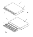
- the overall structure which forms the retractable step has been marked with the reference numeral 1; as shown in Figs. 1 and 2 , the step includes a tread 2, retractable with respect to a housing body 3that encloses the motor and transmission means.
- the whole set 1 is stably associated to the vehicle, by fixing the body (3) to the frame of the latter in the chosen position.
- the housing body 3 comprises a lower base 28, provided with a rear bottom part 28A, two flanks 26, an upper cover 31, and a front closing wall 29, open and shaped so as to allow the passage of the tread through it.
- the tread in this example is composed of two parts 9 and 90, to allow a modularity in amplitude (depth) of the tread, or to form steps differently dimensioned; obviously the tread can be formed by a single element.
- the treads and the parts that form the container body may be made of material mechanically resistant and light like, for example, aluminum, and possibly formed by extrusion.
- the tread is closed at the bottom by a bottom cover surface 30.
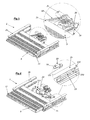
- Two side plates 25 are associated to the tread 9, by means of screws 10.
- the reference numeral 10 will be used even for screws arranged in other positions.
- each side plate 25 On the distal portion of each side plate 25 is applied a cover plate (11 and 12, respectively to the right and to the left in Fig.3 ).
- the proximal part of each side plate 25 is fixed to a sliding pad 23, that can be made of plastic material.
- the sliding pad 23 is provided with sliding portions destined to be in contact with corresponding portions of the flanks 26 of the container body, as described below.
- the sliding pad 23 is provided with two appendixes 234 that have a convex shape on the the top side, this side being destined to slide in a corresponding seat 261 of the flank 26; inferiorly, the sliding pad 23 is provided with two appendixes 230, which are concave on the lower side 231, so as to define a concave seat that can be fitted on a corresponding convex portion 260 of the flank 26.
- the lower extension 230 of the sliding pad 23 has a discontinuity on its lower side, thus defining a tooth 233 with two open parts 232 at both its sides to eliminate or at least drastically reduce the possible accumulation of dirt and/or debris in the sliding area.
- the body defined by the portion 260 of the flank 26 is not completely covered, but said portion is only partially covered, so as to form a discharge route through which dirt can exit without accumulating.
- the teeth 233 are arranged offset on the opposite sides of the body 260. In this way, it is ensured the guide of the sliding pad 23 when it slides along the body 260, but the opposite sides of the same body 260 are not completely covered by said appendix 230.
- each of the side plates 25 of the tread 9, provided with the respective pad 23, can slide along the direction of movement of the step along the guides defined by the flanks 26 of the container body 3.
- the support element 22 has a lower groove 221 which is destined to be coupled with the protrusion 260 of the sidewalls 26 and is superiorly provided with an open channel 220, intended to receive the lower edge of the corresponding flank 25 of the tread 9, 90.
- the tread 9, 90 can slide with respect to the container body 3 because the same tread is provided with the side plates 25 that slide in the corresponding flanks 26 thanks to the presence of the sliding pads 23 and the support elements 22.
- the pin 24 is formed by a body (realizable in plastic material) substantially cylindrical provided with an end 240 in which there is a hook which temporarily and elastically reduces its overall dimensions when it is introduced in a hole dimensioned to receive it.
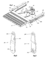
- Each of the pins 24 is intended to pass through a corresponding hole 180 presented at a first end by a connecting rod 18, forming a link between the connecting rod 18 and the tread, allowing the rotation of the same connecting rod 18 about the axis defined by the pin 24.
- the connecting rod 18 is provided with a coupling element 181, constituted by a cylindrical body projecting axially from the connecting rod and having a radial appendix 182.
- the outer face of the coupling element 181 is therefore represented by a circular shape provided with a radial tooth 182.
- the shape of the connecting rods 18 is substantially rectilinear, with a bent part, according to the angle indicated by ⁇ in the drawings, at the ends which support the coupling elements 181. In particular, these ends are turned towards the inside when the two connecting rods are assembled; in practice, when the connecting rods 18 are mounted, the respective bent parts are directed towards each other.
- the coupling element 181 is intended to pass through a corresponding slotted housing 200 provided at a first end of a lever or crank 20.
- the crank 20 is provided, at the opposite end, with a through-hole 201.
- the two cranks 20 are pivoted to the connecting rods 18, so as to be rotatable with respect to the latter, being able to rotate about the axis defined by the coupling element 181.
- one of the two cranks 20 is provided with a tooth 203 adapted to interfere with a limit switch 5 as described below.
- the step 1 further comprises a casing formed by two half-shells 13 and 17, which are joined yop each other to form a closed container.
- the lower half-shell 13 is provided with three cylindrical supports 130, 131, 132 that protrude toward the inside of the casing (i.e. upwardly with respect to the half-shell).
- Two toothed wheels 14 are rotatably fitted on the cylindrical supports 130 and 131 , said wheels being identical to each other and having a first toothing 140 which extends over the entire contour of the wheel, and a second set of teeth 141, of smaller diameter than the first, arranged on a different plane (an upper plane in the drawings) and so shaped as to be complementary to the groove 202 of the crank 20 which, therefore, can be easily connected to the same toothed wheel.
- a pinion 15 On the cylindrical support 132 it is rotatably fitted a pinion 15, provided with an internal toothing and an external toothing.
- the internal toothing of the pinion 15 is shaped in a complementary manner in respect to the toothing of a grooved motor shaft 16 driven in rotation by a motor 35.
- the external toothing is suitable to mesh with the external teeth 140 of one of the wheels 14.
- the supports 130, 131, 132 are arranged such that the two wheels 14 mesh with each other and the pinion 15 engages only one of the two wheels.
- the distance DB between the support 130 and the support 132 will be greater than the value of the distance DA between the support 131 and the support 132, so that the wheel 14 disposed on the right is engaged by the pinion 13 and transmits the motion to the wheel 14 arranged on the left.
- a rotation of the pinion 15 corresponds to opposite rotations of the two toothed wheels 14; for instance, again with reference to the position of Figure 4 , the clockwise rotation of the pinion 15 corresponds to a counterclockwise rotation of the right wheel 14 meshed directly to it and a clockwise rotation of the left wheel 14 which is meshed with the wheel positioned on the right.
- the upper half-shell 17 is provided with a through hole for the passage of the motor shaft 16 and with two through holes, through which pass the second sets of teeth 141 of the toothed wheels 14.
- the grooved shaft 16 is driven by the motor 35 which is provided with a housing coverage so as to cover the relative hole.
- the ends of the cranks 20 which rotate as the same wheels because the teeth 141 are stably inserted in the grooved seats 202.
- the upper half-shell 17 has a rear cavity 170 intended to accommodate a micro-switch 5 adapted to detect the positioning of the retractable step by controlling the end-stroke position of the crank 203 mentioned above.
- a micro-switch 5 adapted to detect the positioning of the retractable step by controlling the end-stroke position of the crank 203 mentioned above.
- each crank 20 is located in a position substantially parallel to the direction of displacement of the tread. In this way, the rotation of one of the cranks 20 (the one arranged on the left in Figure 7 ) brings the tooth 203 to interfere with the movable element 50 of the micro-switch 5.
- the switch 5 is within the protection cover to avoid bad contacts and/or malfunction.
- the step is also provided with release means that allow to bring the step in the retracted position in case of malfunctions.
- a spring 34 pushes down the motor shaft 16 so as to stabilise the connection motor 35 - drive shaft 16 - pinion 15 - gear wheels 14.
- the lower half-shell is provided with a hole 133, which can be kept closed by an easily removable cap (not shown); through the hole 133 it is possible to access to the pinion 15, making it slide axially with respect to the motor shaft 16 and thus decoupling the motor from the gear wheels 14.
- This operation can be executed, for example, using a screw or other suitable tool to move upwards (see the direction of the arrow F) the pinion 15, thus disengaging it from the wheel 14 to which it is normally engaged.
- Fig. 5 shows the closed position, that is, the retracted configuration.
- the tread 9, 90 is completely retracted inside the body 3; the cranks 20 and the connecting rods 18 are in the position of maximum retraction, i.e. each crank 20 is arranged substantially parallel to the direction of movement of the tread and the corresponding connecting rod 18 forms a small angle with it because of its slightly bent portion.
- some elements such as, for example, the toothed wheels 14, the pinion 15, the grooved shaft 16, the sliding pads 23, the support elements 22, as well as the connecting rods 18 and the cranks 20, can be made in plastic material of the so-called self-lubricating; for example, it can be used a resin reinforced with glass fiber.
- plastic material of the so-called self-lubricating; for example, it can be used a resin reinforced with glass fiber.
- Figs.24 and 25 show another embodiment of the system described above, in which the toothed wheels 14 do not mesh with each other but the first toothed wheel 14 meshes with the pinion 15 as in the previous example, while the second toothed wheel 14 meshes with an idle sprocket RF interposed between the pinion 15 and the second toothed wheel 14.
- Such solution allows to space from each other the rotation axes of the toothed wheels 14 without having to increase their diameter and, thus, it is possible to move wider steps whilst ensuring the symmetry of the forces exerted on the tread.
Landscapes
- Engineering & Computer Science (AREA)
- Mechanical Engineering (AREA)
- General Engineering & Computer Science (AREA)
- Lock And Its Accessories (AREA)
- Vehicle Step Arrangements And Article Storage (AREA)
- Bidet-Like Cleaning Device And Other Flush Toilet Accessories (AREA)
- Stringed Musical Instruments (AREA)
Applications Claiming Priority (1)
| Application Number | Priority Date | Filing Date | Title |
|---|---|---|---|
| ITFI2014U000055U ITFI20140055U1 (it) | 2014-10-01 | 2014-10-01 | Gradino a scomparsa. |
Publications (2)
| Publication Number | Publication Date |
|---|---|
| EP3002156A2 true EP3002156A2 (de) | 2016-04-06 |
| EP3002156A3 EP3002156A3 (de) | 2016-05-18 |
Family
ID=54541924
Family Applications (1)
| Application Number | Title | Priority Date | Filing Date |
|---|---|---|---|
| EP15184588.0A Withdrawn EP3002156A3 (de) | 2014-10-01 | 2015-09-10 | Einfahrbare stufe |
Country Status (2)
| Country | Link |
|---|---|
| EP (1) | EP3002156A3 (de) |
| IT (1) | ITFI20140055U1 (de) |
Cited By (1)
| Publication number | Priority date | Publication date | Assignee | Title |
|---|---|---|---|---|
| IT202200015747A1 (it) | 2022-07-26 | 2024-01-26 | Bode Sud S P A | Gradino retrattile automatizzato per veicoli |
Citations (1)
| Publication number | Priority date | Publication date | Assignee | Title |
|---|---|---|---|---|
| EP1393977A1 (de) | 2002-08-29 | 2004-03-03 | Omnistor Accessories, naamloze vennootschap | Ausfahrbare Trittstufe |
Family Cites Families (9)
| Publication number | Priority date | Publication date | Assignee | Title |
|---|---|---|---|---|
| US5305486A (en) * | 1993-06-24 | 1994-04-26 | Wheelers Manufacturing, Inc. | Vehicle passenger boarding system |
| US6102648A (en) * | 1997-09-05 | 2000-08-15 | Ricon Corporation | Driving mechanism for vehicle lifts |
| DE60203296T2 (de) * | 2001-06-11 | 2006-04-13 | Tribotek Inc., Cambridge | Kontaktlager |
| US7527467B2 (en) * | 2003-01-29 | 2009-05-05 | The Braun Corporation | Retractable ramp system for a mobility vehicle |
| FR2939735A1 (fr) * | 2008-12-12 | 2010-06-18 | Faiveley Transp Tours | Dispositif deployable pour l'acces a un vehicule |
| EP2390142B1 (de) * | 2010-05-31 | 2013-07-31 | Hübner Transportation GbmH | Vorrichtung zur ausfahrbaren Aufnahme einer Rampe |
| KR101262910B1 (ko) * | 2012-08-27 | 2013-05-09 | 황성공업 주식회사 | 전동식 스텝장치 |
| CN203093649U (zh) * | 2012-09-30 | 2013-07-31 | 常州市德思特机械有限公司 | 轮滑架 |
| CN203297348U (zh) * | 2013-05-23 | 2013-11-20 | 衢州兰玲机电科技有限公司 | 自洁型滑杆 |
-
2014
- 2014-10-01 IT ITFI2014U000055U patent/ITFI20140055U1/it unknown
-
2015
- 2015-09-10 EP EP15184588.0A patent/EP3002156A3/de not_active Withdrawn
Patent Citations (1)
| Publication number | Priority date | Publication date | Assignee | Title |
|---|---|---|---|---|
| EP1393977A1 (de) | 2002-08-29 | 2004-03-03 | Omnistor Accessories, naamloze vennootschap | Ausfahrbare Trittstufe |
Cited By (2)
| Publication number | Priority date | Publication date | Assignee | Title |
|---|---|---|---|---|
| IT202200015747A1 (it) | 2022-07-26 | 2024-01-26 | Bode Sud S P A | Gradino retrattile automatizzato per veicoli |
| EP4311725A1 (de) | 2022-07-26 | 2024-01-31 | Bode Sud S.p.A. | Automatisch einziehbare trittstufe für fahrzeuge |
Also Published As
| Publication number | Publication date |
|---|---|
| ITFI20140055U1 (it) | 2016-04-01 |
| EP3002156A3 (de) | 2016-05-18 |
Similar Documents
| Publication | Publication Date | Title |
|---|---|---|
| EP3002157A2 (de) | Einziehbare stufe | |
| CN105584332B (zh) | 用于车辆的滑动车门装置 | |
| EP3332078B1 (de) | Scharniervorrichtung mit langer hubbewegung einer frontplatte | |
| EP2772424B1 (de) | Fahrradkettenschaltung, insbesondere ein vorderer Umwerfer, mit verbesserter Zuverlässigkeit | |
| US8243137B2 (en) | Device for opening a vehicle lock and for capturing an image on the exterior of the vehicle | |
| CN106218369B (zh) | 用于车辆的滑动车门装置 | |
| CN106030013B (zh) | 门弹开装置 | |
| CA2675785C (en) | Power dual action rocker board | |
| FR3024173A1 (fr) | Ensemble de poignee pour vehicule automobile et ouvrant comprenant un tel ensemble de poignee | |
| JP5902303B2 (ja) | 家具部品を移動させるための同期装置 | |
| EP3194696A1 (de) | Flächenbündiger komfortgriff | |
| FR3023865A1 (fr) | Ensemble de poignee pour vehicule automobile et ouvrant comprenant un tel ensemble de poignee | |
| DE102013109914A1 (de) | Abdeckklappenanordnung für eine Handgriffanordnung einer Kraftfahrzeugtür | |
| EP3002156A2 (de) | Einfahrbare stufe | |
| FR3001488A1 (fr) | Ensemble pour verrouiller et deverrouiller un ouvrant articule a un dormant | |
| FR2601992A1 (fr) | Groupe modulaire serrure cylindrique-barillet | |
| EP2799652A1 (de) | Schiebetor | |
| RU2014119910A (ru) | Электрический поворотный привод для устройства входа и выхода, в частности для двери | |
| IT201900003557A1 (it) | Maniglia a cariglione per infissi | |
| IT201900013797A1 (it) | Serratura | |
| DE3026037A1 (de) | Fahrzeugschiebetuer | |
| RU69903U1 (ru) | Устройство для открывания и закрывания сдвижной двери транспортного средства | |
| KR101374524B1 (ko) | 시트의 매뉴얼 럼버서포트 장치 | |
| RU62632U1 (ru) | Устройство для открывания и закрывания сдвижной двери транспортного средства | |
| FR2925099A3 (fr) | Agencement de porte de coffre de vehicule automobile |
Legal Events
| Date | Code | Title | Description |
|---|---|---|---|
| PUAI | Public reference made under article 153(3) epc to a published international application that has entered the european phase |
Free format text: ORIGINAL CODE: 0009012 |
|
| AK | Designated contracting states |
Kind code of ref document: A2 Designated state(s): AL AT BE BG CH CY CZ DE DK EE ES FI FR GB GR HR HU IE IS IT LI LT LU LV MC MK MT NL NO PL PT RO RS SE SI SK SM TR |
|
| AX | Request for extension of the european patent |
Extension state: BA ME |
|
| PUAL | Search report despatched |
Free format text: ORIGINAL CODE: 0009013 |
|
| AK | Designated contracting states |
Kind code of ref document: A3 Designated state(s): AL AT BE BG CH CY CZ DE DK EE ES FI FR GB GR HR HU IE IS IT LI LT LU LV MC MK MT NL NO PL PT RO RS SE SI SK SM TR |
|
| AX | Request for extension of the european patent |
Extension state: BA ME |
|
| RIC1 | Information provided on ipc code assigned before grant |
Ipc: B60R 3/02 20060101AFI20160414BHEP |
|
| STAA | Information on the status of an ep patent application or granted ep patent |
Free format text: STATUS: THE APPLICATION IS DEEMED TO BE WITHDRAWN |
|
| 18D | Application deemed to be withdrawn |
Effective date: 20161119 |