EP3000534B1 - Apparatus for applying paint to products - Google Patents
Apparatus for applying paint to products Download PDFInfo
- Publication number
- EP3000534B1 EP3000534B1 EP15186126.7A EP15186126A EP3000534B1 EP 3000534 B1 EP3000534 B1 EP 3000534B1 EP 15186126 A EP15186126 A EP 15186126A EP 3000534 B1 EP3000534 B1 EP 3000534B1
- Authority
- EP
- European Patent Office
- Prior art keywords
- arm
- shuttling
- plenum
- paint
- shape
- Prior art date
- Legal status (The legal status is an assumption and is not a legal conclusion. Google has not performed a legal analysis and makes no representation as to the accuracy of the status listed.)
- Active
Links
Images



Classifications
-
- B—PERFORMING OPERATIONS; TRANSPORTING
- B05—SPRAYING OR ATOMISING IN GENERAL; APPLYING FLUENT MATERIALS TO SURFACES, IN GENERAL
- B05B—SPRAYING APPARATUS; ATOMISING APPARATUS; NOZZLES
- B05B13/00—Machines or plants for applying liquids or other fluent materials to surfaces of objects or other work by spraying, not covered by groups B05B1/00 - B05B11/00
- B05B13/02—Means for supporting work; Arrangement or mounting of spray heads; Adaptation or arrangement of means for feeding work
- B05B13/04—Means for supporting work; Arrangement or mounting of spray heads; Adaptation or arrangement of means for feeding work the spray heads being moved during spraying operation
- B05B13/0431—Means for supporting work; Arrangement or mounting of spray heads; Adaptation or arrangement of means for feeding work the spray heads being moved during spraying operation with spray heads moved by robots or articulated arms, e.g. for applying liquid or other fluent material to three-dimensional [3D] surfaces
-
- B—PERFORMING OPERATIONS; TRANSPORTING
- B05—SPRAYING OR ATOMISING IN GENERAL; APPLYING FLUENT MATERIALS TO SURFACES, IN GENERAL
- B05B—SPRAYING APPARATUS; ATOMISING APPARATUS; NOZZLES
- B05B16/00—Spray booths
- B05B16/60—Ventilation arrangements specially adapted therefor
-
- B—PERFORMING OPERATIONS; TRANSPORTING
- B05—SPRAYING OR ATOMISING IN GENERAL; APPLYING FLUENT MATERIALS TO SURFACES, IN GENERAL
- B05B—SPRAYING APPARATUS; ATOMISING APPARATUS; NOZZLES
- B05B13/00—Machines or plants for applying liquids or other fluent materials to surfaces of objects or other work by spraying, not covered by groups B05B1/00 - B05B11/00
- B05B13/02—Means for supporting work; Arrangement or mounting of spray heads; Adaptation or arrangement of means for feeding work
- B05B13/04—Means for supporting work; Arrangement or mounting of spray heads; Adaptation or arrangement of means for feeding work the spray heads being moved during spraying operation
- B05B13/0405—Means for supporting work; Arrangement or mounting of spray heads; Adaptation or arrangement of means for feeding work the spray heads being moved during spraying operation with reciprocating or oscillating spray heads
- B05B13/041—Means for supporting work; Arrangement or mounting of spray heads; Adaptation or arrangement of means for feeding work the spray heads being moved during spraying operation with reciprocating or oscillating spray heads with spray heads reciprocating along a straight line
- B05B13/0415—Means for supporting work; Arrangement or mounting of spray heads; Adaptation or arrangement of means for feeding work the spray heads being moved during spraying operation with reciprocating or oscillating spray heads with spray heads reciprocating along a straight line the angular position of the spray heads relative to the straight line being modified during the reciprocating movement
-
- B—PERFORMING OPERATIONS; TRANSPORTING
- B05—SPRAYING OR ATOMISING IN GENERAL; APPLYING FLUENT MATERIALS TO SURFACES, IN GENERAL
- B05B—SPRAYING APPARATUS; ATOMISING APPARATUS; NOZZLES
- B05B13/00—Machines or plants for applying liquids or other fluent materials to surfaces of objects or other work by spraying, not covered by groups B05B1/00 - B05B11/00
- B05B13/02—Means for supporting work; Arrangement or mounting of spray heads; Adaptation or arrangement of means for feeding work
- B05B13/04—Means for supporting work; Arrangement or mounting of spray heads; Adaptation or arrangement of means for feeding work the spray heads being moved during spraying operation
- B05B13/0447—Installation or apparatus for applying liquid or other fluent material to conveyed separate articles
-
- B—PERFORMING OPERATIONS; TRANSPORTING
- B05—SPRAYING OR ATOMISING IN GENERAL; APPLYING FLUENT MATERIALS TO SURFACES, IN GENERAL
- B05B—SPRAYING APPARATUS; ATOMISING APPARATUS; NOZZLES
- B05B16/00—Spray booths
- B05B16/40—Construction elements specially adapted therefor, e.g. floors, walls or ceilings
- B05B16/405—Partly or totally cylindrical walls; Round floors
Definitions
- the present invention relates to the technical field of apparatuses for applying paint to products, in particular to products with a basically flat extent, known on the market as paint spraying booths.
- the present invention relates to a shuttling arm, to which the following description will make explicit reference without narrowing the scope of the description.
- Spraying booths are known that comprise movable automatic devices (reciprocators, carousels, rotating arms) for spray painting products to be painted and which further comprise a conveying system for advancing the products inside the spraying booth in a direction of advancement.
- the automatic spraying devices apply the paint during the advancement of the products, when the latter are in a painting zone.
- Spray paint application entails that not all the paint hits the product; the paint not applied to the product partly finishes on the product conveying system, and partly hovers in the air in the spraying booth itself. This last portion of sprayed paint is called overspray, and is partially intercepted by the spraying booth suction system.
- Non-intercepted overspray tends to contaminate spraying booth internal walls, gathering on them up to the point of compromising manufacturing quality and leading to an important waste of painted products. Therefore costly maintenance and cleaning of the spraying booth itself become mandatory.
- the overspray intercepted by the suction system is channelled towards filters of the spraying booth, also thanks to an air flow produced by the suction system itself, too. In this path the overspray is controlled in a more proper way thanks to the emission of an air flow from the plenum.
- a spraying booth 12 in which a conveying system 13 is provided that conveys a product 14 in a direction of advancement D and a plenum 15 of curved, in particular semicylindrical shape, having a longitudinal axis of symmetry Y arranged perpendicular to the direction of advancement D of the product 14.
- Suction means 16 is provided on both sides of the conveying system 13.
- the spraying booth further comprises two spraying devices 17 arranged on respective shuttling arms, (which are not illustrated), which are arranged slidable on respective guides (which are not illustrated).
- the latter are parallel to the longitudinal axis of symmetry Y of the plenum 15 and are respectively fixed to lateral walls of the spraying booth.
- the spraying devices 17 are thus arranged facing one another to spray paint from opposite sides of the booth, they are preferably arranged at the same height and are each moved by the respective arm along the respective guide, by a control system of the spraying booth in relation to the portion of product to be painted such as to be translated in the guides along the respective longitudinal axes, which are parallel to the longitudinal axis of symmetry Y of the plenum 15.
- the plenum 15 in combination with the suction means 16 of the cabin 12 generate an air whirl that enables the phenomenon of overspray to be contained.
- the present invention seeks to provide a spraying booth with further improved cleaning features.
- a further object of the present invention is to provide a spraying booth that rarely needs onerous spraying booth cleaning/maintenance operations.
- the aim is achieved through the combination of a plenum and of a supporting arm of the spraying devices according to the present invention, according to which the arm has a shape that is at least partially complementary to that of the plenum.
- the shape of the shuttling arm which is as similar as possible to the shape of the plenum, means that the shuttling arm follows the shape of the whirl generated by the combination between the plenum and the suction without disturbing the air whirl itself.
- the shuttling arm adheres as closely as possible to the plenum, in particular it is at a distance from the plenum ranging from 5mm to 150mm, precisely to avoid interfering as much as possible with the air whirl.
- the shuttling arm has a shape that is symmetrical with respect to a longitudinal axis of symmetry of the plenum and is fixed by a central portion to supporting elements which are in turn fixed at the axis of symmetry of the plenum.
- the shuttling arm is supported by an upper central zone of the plenum and follows the shape of the plenum to spray paint on the products from top to bottom so that the overspray paint is hit by the air flow emitted by the plenum and is conveyed in the air whirl generated by the combination between the plenum and the suction, without the air whirl being disturbed.
- the plenum has a curved shape, in particular semicylindrical shape
- the shuttling arm thus has a curved shape, in particular substantially semicylindrical shape that is at least partially complementary with the shape of the plenum, and if moreover the shuttling arm is positioned to adhere as close as possible to the plenum.
- This particular embodiment permits an effective control of the overspray inside the spraying booth because the central top portion of the plenum keeps low the whirl that is generated by the suction system and the lateral walls of the plenum maintain the air whirl compressed towards the centre of the spraying booth, the shuttling arm not interfering with the air whirl.
- an apparatus for painting products (which are not illustrated) has been illustrated, which is also commonly known as spraying booth.
- the products can also, e.g., have a basically flat extent.
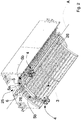
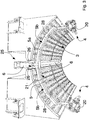
- the apparatus 1 comprises a flat conveying system 2 (shown in Figure 1 ) and at least one paint applying device 4, fixed to a shuttling arm 5, at least one suction system (not shown) and a plenum 3 that is provided with a longitudinal axis A which is perpendicular to a direction of advancement D of the products.
- the longitudinal axis A shown in Figure 2 is a longitudinal axis of symmetry for the plenum 3 itself.
- the plenum 3 is suitable for blowing air whereas the suction system is suitable for sucking the non-applied paint so that the air emitted by the plenum 3 in combination with the air sucked by the suction system can generate an air whirl 7 ( Figure 1 ) that is uniformly distributed and controlled so that paint particles suspended in the painting zone do not accumulate on the walls of the spraying booth because they are effectively sucked by the suction system.
- the device for applying the paint 4 comprises at least one spray gun 20.
- each paint applying device comprises a plurality of spray guns 20, e.g. four spray guns as in Figures 2 to 4 or two spray guns 20 as in Figures 5 to 8 .
- the number of spray guns is selected according to the type of painting to be performed and according to the type of product to be painted and for this reason in the present figures two spray-guns 20 or four spray-gun 20 paint-applying devices are shown.
- the spray guns 20 face a painting zone of the apparatus 1.
- the shuttling arm 5 has a shape that is at least partially complementary to that of the plenum 3.
- the plenum 3 typically has a concave shape and the attached figures show a plenum 3 of curved shape
- the plenum 3 can be made by means of a continuous polyhedral surface or by means of a continuous surface with at least one curved portion.
- the shuttling arm 5 can have a shape that is entirely complementary to the shape of the plenum 3, in the sense that it can follow entirely the profile thereof, or can have a shape that approximates the shape of the plenum 3, following the profile thereof, as will be seen in greater detail below.
- the shuttling arm 5 is hollow and internally both tubes conveying paint 8 and tubes conveying compressed air 9 run, which are received by the paint applying device 4 to spray paint on the products to be sprayed.
- shuttling arm is covered by a surface finishing, e.g. TEFLON®, which permits easy cleaning of the shuttling arm.
- the spraying apparatus 1 further comprises a belt 6, shown in detail at least in figures 2 to 7 , which sets the shuttling arm 5 in motion, the width and the position of the belt 6 being such as to allow the closing of a split 21 where the supporting elements of the shuttling arm 5 slide, so that paint particles cannot enter into the transmission organs (which are not illustrated) of the shuttling arm 5.
- the belt 6 is arranged at the central longitudinal axis of the plenum 3 that is symmetrical for the plenum 3, as will be seen better below.
- the supporting elements support a central portion 5a of the shuttling arm 5.
- the supporting elements comprise a tubular elongated support 22 and a carriage 23.
- the central portion 5a of the shuttling arm 5 is fixed to the carriage 23, which is slidingly supported by the tubular support 22 by a pair of slide shoes and is fixed to the belt 6 that sets the shuttling arm 5 in motion.
- the belt 6 is driven by drive means (which is not illustrated) to drive the shuttling arm 5, the belt drags the carriage 23 which slides on the tubular support 22, in particular, the slide shoes of the carriage slide on a sliding rail 24 ( Figure 4 , Figure 5 and Figure 6 ) of the tubular support 22.
- the movement means of the shuttling arm 5, which comprises the belt 6, the tubular support 22, the carriage 23 and transmission organs (which are not illustrated) are such as to enable the shuttling arm 5 to move from a longitudinal end of the plenum 3 to the opposite longitudinal end.
- the tubular support 22 extends over the entire longitudinal extent of the plenum 3 and the sliding rail 24 extends over the entire length of the tubular support 22, so that the carriage 23 can be slid by the belt 6 over the entire longitudinal extent of the plenum 3 from a longitudinal end of the plenum 3 to the opposite longitudinal end.
- the tubular support 22 is arranged at the longitudinal axis of symmetry of the plenum 3.
- An elongated seat 25 is obtained in the plenum 3 to house the supporting elements and the transmission elements of the shuttling arm 5.
- a pair of elongated elements 26 are further arranged on the sides of the central portion 5a of the shuttling arm 5 and between the sides the split 21 is defined that is closed by the belt 6, which thus prevents the paint particles entering the seat 25 in which the supporting elements and the transmission organs of the shuttling arm 5 are housed.
- the apparatus 1 comprises two paint applying devices 4 and the shuttling arm 5 comprises two lateral portions 5b, which are arranged on opposite sides to the central portion 5a.
- Each lateral portion 5b has a shape that is at least complementary to the shape of the plenum 3 and further supports a respective paint applying device 4.
- Each lateral portion 5b further has an end provided with adjustment guides for adjusting a position of the respective paint applying device 4, the position of the paint applying device 4 in the adjustment guides being adjustable both vertically (moving the paint applying device 4 towards or away from the products to be painted) and horizontally (i.e. moving the paint applying devices 4 towards or away from one another).
- the paint applying device 4 comprises a plate 10, which supports the spray guns 20 and is fixed slidably on a vertical guide 11 and on which the position of the spray guns 20 can be adjusted, as the spray guns 20 are mounted slidably on respective horizontal guides (which are not illustrated) that enable the spray guns 20 to slide towards or away from one another.
- each spray gun 20 in relation to the painting zone can further be adjusted, because each spray gun 20 can be adjusted according to two rotation axes that are orthogonal to one another.
- Each lateral portion 5b in addition to the central portion 5a, is further hollow, for housing internally the tubes conveying the paint 8 and the tubes conveying compressed air 9. Further, each lateral portion 5b comprises a respective filter 27 for the paint arranged inside the vertical guide 11 to filter the paint to be applied, that is conveyed to the spray guns 20. The filter 27 is upstream of the spray guns 20.
- the filter 27 is arranged dismantleable at the lower end of the vertical guide 11 to enable a maintenance operator to be able to access and dismantle easily the filter 27.
- the lateral portions 5a of the shuttling arm 5 are made of a plurality of hollow tubular elements 28 that are joined together, e.g. jointed and/or welded, which enable a shuttling arm of the desired stiffness to be made, whilst maintaining the costs limited.
- the shape of the shuttling arm can only approximate the curved shape of the plenum 3, following any way the profile thereof with a shape that is at least partially complementary to that of the plenum 3.
- the shuttling arm 5 has an axis of symmetry that is parallel to the longitudinal axis of symmetry A of the plenum 3 as lateral portions 5b of the shuttling arm 5 are symmetrical to the central portion 5a of the shuttling arm 5.
- shuttling arm 5 that follows the profile of the plenum 3, when preferably the shuttling arm 5 is slidably fixed at the longitudinal axis of symmetry A of the plenum 3 and is symmetrical thereto with respect to the axis of symmetry A or to an axis parallel to the longitudinal axis of symmetry A.
- the shuttling arm 5 adheres as much as possible to the plenum and thus has a distance from the plenum comprised in a range between 5mm and 150 mm.
- the lateral portions 5b of the shuttling arm 5 that adhere as much as possible to the plenum, at a distance from the plenum comprised in a range between 5mm to 150mm.
- the plenum is of concave shape, in particular it is curved, more in particular of semicylindrical shape.
- the association between the position of the shuttling arm 5 adhering to the plenum 3, the semicylindrical curved shape of the plenum 3 and the shape of the shuttling arm 5 that follows the profile of the semicylindrical plenum means that there is maximum spraying efficiency of the spraying booth, improving the downflow of the overspray from the spraying booth 1.
- the spraying apparatus 1 comprises a control system comprising detecting means 29 for detecting the dimensions of the product to be painted and a painting control device 30 that is suitable for adjusting a stroke of the shuttling arm 5 on the basis of the dimension detected by the detecting means 29.
- the control device 30 calculates a first end position and a second end position of the tubular support 22 between which the shuttling arm 5 is to be moved in both movement directions.
- the control device 30 is also suitable for adjusting a sliding speed of the shuttling arm 5 in the tubular support 22, in particular in the sliding rail 24 to optimise painting of the products by decreasing the time required for painting.
- the conveying system 2 advances the product to be painted to the inside of the spraying apparatus and when the product is in a painting zone, the control device 30 establishes a painting plan for the product on the basis of the dimensions detected by the detecting means 29, and thus establishes the first end movement position and the second end movement position in the tubular support 22 to define the stroke 31 of the shuttling arm 5, and the speed 32 at which this movement is to be run.
- shuttling arm 5 The movement of the shuttling arm 5 and thus the activation of the painting have to be synchronised with an advancing speed of the conveying system 2, as the shuttling arm 5 is suitable for spraying paint during the advancement of each product.
- Figure 1 shows the section, on a plan parallel to the direction of advancement of the product to be painted, of the interior of the spraying booth 1.
- a conveying system 2 for conveying the products (which are not shown), at least one paint applying device 4 (e.g. a spray gun), and a plenum 3 of the spraying booth having a semicylindrical shape with an axis perpendicular to the direction (shown by the bold arrow) of advancement of the products.
- a paint applying device 4 e.g. a spray gun
- a plenum 3 of the spraying booth having a semicylindrical shape with an axis perpendicular to the direction (shown by the bold arrow) of advancement of the products.
- the plenum 3 is a ceiling distributing an airflow, capable of generating a uniformly distributed and controlled airflow.
- the combination of the in-flow and suctioned flow, together with the shape of the plenum, allows an air whirl 7 (shown in the form of a spiralling arrow) to be generated, having its axis perpendicular to the direction of advancement of the products to be painted.
- the shuttling arm 5 supporting at least one painting device 4 has a curved shape complementary to that of the plenum 3, so as to interfere as little as possible with the air whirl 7.
- the arm 5 supporting the paint applying devices 4 shuttles back and forth inside the spraying booth 1 in a direction perpendicular to the direction of advancement of the products, and parallel to the axis of the whirl 7.
- the complementary shape of the arm 5 and of the plenum 3, and the minimal distance between arm 5 and plenum 3, allow the air flow coming from the plenum to keep the arm itself clean, reducing the soiling of the arm due to overspray.
- the arm 5 preferably has stiffness such as to reduce as much as possible the vibrations of the machine, and in particular of the paint applying devices 4, so as to prevent the falling of possible contaminant particles onto the products.
- the shape and the dimensions of the arm 5 are such as to ensure the desired stiffness.
- the arm 5 is produced from tubes cut by laser 3D and subsequently welded together.
- the arm 5 can be made of steel, aluminium, carbon, or composite materials allowing the weight to be reduced while maintaining high stiffness.
- the arm 5 is protected by a surface finishing able to withstand solvents, allowing an easy cleaning (e.g. Teflon).
- a surface finishing able to withstand solvents allowing an easy cleaning (e.g. Teflon).
- the arm 5 is hollow, allowing the tubes conveying paint and compressed air to pass that are necessary for the functioning of the painting devices 4.
- FIG. 1 the tubes 8 conveying paint and the tubes 9 conveying compressed air to the devices 4 are visible.
- Housing paint and compressing air tubes inside the arm 5 allows a tidier arrangement inside the spraying booth 1 and a lower number of surfaces which can enter into contact with overspray to be obtained.
- a belt 6 sets the arm 5 in motion.
- the width and the position of the belt 6 are such as to allow the closing of the split where the supporting elements of the arm 5 lie, so that paint particles cannot enter the transmission organs above the spraying booth, and possible dirty particles cannot fall back inside the spraying booths and onto the products.
- This system of sealing the spraying booth by the belt further prevents the formation of airflows which might jeopardize the correct formation of air whirl 7.
- the stroke of the arm 5 is adjustable: it is possible to set its shuttling between two points which can be defined according to the product to be painted; in the preferred embodiment, this adjustment is automatic thanks to the presence of sensors detecting the dimensions of the product.
- the speed of the arm 5 is adjustable: this adjustment occurs on the basis of the advancing speed of the conveying system 2, and of other factors, like e.g. the kind of paint or of guns used.
- the position of the guns fixed to a plate 10 can be adjusted in height thanks to the presence of a vertical adjustment guide 11 allowing the guns to move away from or towards the products to be painted.
- the plate 10 allows moreover the horizontal adjustment of the position of guns for applying the paint even in the direction of the advancing parts (the guns can be moved towards or away from one another).
- the guns can be adjusted according to two rotation axes that are orthogonal to one another, one perpendicular (vertical axis) to the conveying system 2, and one perpendicular (horizontal axis) to the axis of the gun itself.
- a filter for the paint is housed, which allows impurities or clots possibly present in the paint to be sprayed to be intercepted, so as to prevent nozzle obstruction and ensuring a uniform paint application.
- the guns for applying the paint can be replaced by any other commercial type of paint-spraying device.
Landscapes
- Engineering & Computer Science (AREA)
- Robotics (AREA)
- Spray Control Apparatus (AREA)
- Details Or Accessories Of Spraying Plant Or Apparatus (AREA)
- Application Of Or Painting With Fluid Materials (AREA)
Priority Applications (1)
| Application Number | Priority Date | Filing Date | Title |
|---|---|---|---|
| PL15186126T PL3000534T3 (pl) | 2014-09-26 | 2015-09-21 | Urządzenie do nakładania farby na produkty |
Applications Claiming Priority (1)
| Application Number | Priority Date | Filing Date | Title |
|---|---|---|---|
| ITBO20140530 | 2014-09-26 |
Publications (2)
| Publication Number | Publication Date |
|---|---|
| EP3000534A1 EP3000534A1 (en) | 2016-03-30 |
| EP3000534B1 true EP3000534B1 (en) | 2018-01-31 |
Family
ID=51753290
Family Applications (1)
| Application Number | Title | Priority Date | Filing Date |
|---|---|---|---|
| EP15186126.7A Active EP3000534B1 (en) | 2014-09-26 | 2015-09-21 | Apparatus for applying paint to products |
Country Status (5)
| Country | Link |
|---|---|
| EP (1) | EP3000534B1 (pl) |
| CN (1) | CN105457818B (pl) |
| ES (1) | ES2660444T3 (pl) |
| PL (1) | PL3000534T3 (pl) |
| TR (1) | TR201802350T4 (pl) |
Families Citing this family (9)
| Publication number | Priority date | Publication date | Assignee | Title |
|---|---|---|---|---|
| CN112269358B (zh) * | 2017-10-09 | 2022-08-26 | 山东云途供应链管理有限公司 | 一种用于管式物流系统的安全控制方法 |
| CN107670886B (zh) * | 2017-11-14 | 2019-04-30 | 贵州环科环境工程有限公司 | 一种喷漆回收装置 |
| CN107961937A (zh) * | 2017-11-23 | 2018-04-27 | 中山市君禾机电设备有限公司 | 一种粉末喷房 |
| CN107670885A (zh) * | 2017-11-30 | 2018-02-09 | 成都大运汽车集团有限公司 | 一种汽车外壳喷漆装置 |
| CN109985770B (zh) * | 2018-01-03 | 2021-04-16 | 华晨宝马汽车有限公司 | 用于对车辆翼缘进行涂装的枪嘴和向车辆上胶的方法 |
| CN108906453B (zh) * | 2018-09-25 | 2023-12-26 | 海盐浦兴金属制品有限公司 | 一种灯具外壁喷涂装置 |
| IT201900009711A1 (it) * | 2019-06-21 | 2020-12-21 | Cefla Soc Cooperativa | Apparato per la applicazione di vernici su manufatti a prevalente estensione piana |
| CN114345602B (zh) * | 2022-02-21 | 2023-02-03 | 金肯职业技术学院 | 一种智能plc控制u形件喷涂机器人及其喷涂方法 |
| CN114769038A (zh) * | 2022-05-09 | 2022-07-22 | 苏伟 | 一种耐火材料喷涂装置及喷涂方法 |
Citations (1)
| Publication number | Priority date | Publication date | Assignee | Title |
|---|---|---|---|---|
| ITBO20130182A1 (it) * | 2013-04-22 | 2014-10-23 | Cefla Coop | Metodo e apparecchiatura per la applicazione di vernici su manufatti a prevalente estensione piana |
Family Cites Families (3)
| Publication number | Priority date | Publication date | Assignee | Title |
|---|---|---|---|---|
| CN102101090B (zh) * | 2009-12-18 | 2012-12-26 | 裕东(中山)机械工程有限公司 | 一种立式喷粉房气动清理装置 |
| CN201799355U (zh) * | 2010-08-19 | 2011-04-20 | 浙江宇诚华尔涂装设备制造有限公司 | 静电喷漆室室体 |
| CN103801488B (zh) * | 2014-02-17 | 2017-02-01 | 中山市君禾机电设备有限公司 | 一种应用于粉末喷涂线的立式圆形喷房 |
-
2015
- 2015-09-21 EP EP15186126.7A patent/EP3000534B1/en active Active
- 2015-09-21 ES ES15186126.7T patent/ES2660444T3/es active Active
- 2015-09-21 PL PL15186126T patent/PL3000534T3/pl unknown
- 2015-09-21 TR TR2018/02350T patent/TR201802350T4/tr unknown
- 2015-09-24 CN CN201510616545.XA patent/CN105457818B/zh active Active
Patent Citations (1)
| Publication number | Priority date | Publication date | Assignee | Title |
|---|---|---|---|---|
| ITBO20130182A1 (it) * | 2013-04-22 | 2014-10-23 | Cefla Coop | Metodo e apparecchiatura per la applicazione di vernici su manufatti a prevalente estensione piana |
Also Published As
| Publication number | Publication date |
|---|---|
| CN105457818B (zh) | 2018-09-28 |
| TR201802350T4 (tr) | 2018-03-21 |
| CN105457818A (zh) | 2016-04-06 |
| PL3000534T3 (pl) | 2018-05-30 |
| ES2660444T3 (es) | 2018-03-22 |
| EP3000534A1 (en) | 2016-03-30 |
Similar Documents
| Publication | Publication Date | Title |
|---|---|---|
| EP3000534A1 (en) | Apparatus for applying paint to products | |
| US4864965A (en) | Automatic painting apparatus | |
| CN210146303U (zh) | 衣柜门板数控喷绘系统及其喷绘装置 | |
| EP2808091B1 (en) | Method and apparatus for applying paint on basically flat parts | |
| EP3986619B1 (en) | Apparatus for applying paint on mainly flat parts | |
| US8827673B2 (en) | Device for dry-forming a fibrous web | |
| JP6989712B2 (ja) | コーティングブース | |
| CN206082979U (zh) | 一种通过定位实现精准控制的喷涂装置 | |
| CN104998789B (zh) | 皮革喷涂机内的新型喷枪运行轨道及其喷涂方法 | |
| JP2018047470A (ja) | 管外面の塗装装置 | |
| EP3986620B1 (en) | Apparatus for applying paint to mainly flat parts | |
| CN209829392U (zh) | 一种基于六轴工业机器人的喷涂工作站 | |
| US20050115587A1 (en) | Cleaning device of a powder coating booth | |
| US12350696B2 (en) | Arrangement and method for the preferably automatic coating of objects | |
| JP2017170365A (ja) | 塗装装置 | |
| CN205415334U (zh) | 一种滚轮喷砂机的喷砂机构 | |
| CN116984152B (zh) | 一种油底壳生产用均匀喷涂装置 | |
| CN115351888A (zh) | 上釉机器 | |
| CN109079970A (zh) | 一种喷釉设备 | |
| IT201800005013A1 (it) | Apparecchiatura per l’applicazione di prodotti di decorazione su articoli ceramici | |
| SE467564B (sv) | Saett och anordning foer elektrostatisk applicering av faergpulver i sprutbox | |
| TH21590U (th) | อุปกรณ์และกระบวนการกำจัดครีบชิ้นงาน | |
| TH21590Y (th) | อุปกรณ์และกระบวนการกำจัดครีบชิ้นงาน |
Legal Events
| Date | Code | Title | Description |
|---|---|---|---|
| PUAI | Public reference made under article 153(3) epc to a published international application that has entered the european phase |
Free format text: ORIGINAL CODE: 0009012 |
|
| AK | Designated contracting states |
Kind code of ref document: A1 Designated state(s): AL AT BE BG CH CY CZ DE DK EE ES FI FR GB GR HR HU IE IS IT LI LT LU LV MC MK MT NL NO PL PT RO RS SE SI SK SM TR |
|
| AX | Request for extension of the european patent |
Extension state: BA ME |
|
| 17P | Request for examination filed |
Effective date: 20160929 |
|
| RBV | Designated contracting states (corrected) |
Designated state(s): AL AT BE BG CH CY CZ DE DK EE ES FI FR GB GR HR HU IE IS IT LI LT LU LV MC MK MT NL NO PL PT RO RS SE SI SK SM TR |
|
| RIC1 | Information provided on ipc code assigned before grant |
Ipc: B05B 13/02 20060101ALI20170315BHEP Ipc: B05B 15/12 20060101AFI20170315BHEP |
|
| GRAP | Despatch of communication of intention to grant a patent |
Free format text: ORIGINAL CODE: EPIDOSNIGR1 |
|
| INTG | Intention to grant announced |
Effective date: 20170524 |
|
| GRAJ | Information related to disapproval of communication of intention to grant by the applicant or resumption of examination proceedings by the epo deleted |
Free format text: ORIGINAL CODE: EPIDOSDIGR1 |
|
| GRAS | Grant fee paid |
Free format text: ORIGINAL CODE: EPIDOSNIGR3 |
|
| INTC | Intention to grant announced (deleted) | ||
| RAP1 | Party data changed (applicant data changed or rights of an application transferred) |
Owner name: CEFLA SOCIETA' COOPERATIVA |
|
| GRAP | Despatch of communication of intention to grant a patent |
Free format text: ORIGINAL CODE: EPIDOSNIGR1 |
|
| INTG | Intention to grant announced |
Effective date: 20171024 |
|
| GRAA | (expected) grant |
Free format text: ORIGINAL CODE: 0009210 |
|
| AK | Designated contracting states |
Kind code of ref document: B1 Designated state(s): AL AT BE BG CH CY CZ DE DK EE ES FI FR GB GR HR HU IE IS IT LI LT LU LV MC MK MT NL NO PL PT RO RS SE SI SK SM TR |
|
| REG | Reference to a national code |
Ref country code: GB Ref legal event code: FG4D Ref country code: CH Ref legal event code: EP |
|
| REG | Reference to a national code |
Ref country code: AT Ref legal event code: REF Ref document number: 966859 Country of ref document: AT Kind code of ref document: T Effective date: 20180215 |
|
| REG | Reference to a national code |
Ref country code: IE Ref legal event code: FG4D |
|
| REG | Reference to a national code |
Ref country code: DE Ref legal event code: R096 Ref document number: 602015007724 Country of ref document: DE |
|
| REG | Reference to a national code |
Ref country code: ES Ref legal event code: FG2A Ref document number: 2660444 Country of ref document: ES Kind code of ref document: T3 Effective date: 20180322 |
|
| REG | Reference to a national code |
Ref country code: NL Ref legal event code: MP Effective date: 20180131 |
|
| REG | Reference to a national code |
Ref country code: LT Ref legal event code: MG4D |
|
| REG | Reference to a national code |
Ref country code: AT Ref legal event code: MK05 Ref document number: 966859 Country of ref document: AT Kind code of ref document: T Effective date: 20180131 |
|
| PG25 | Lapsed in a contracting state [announced via postgrant information from national office to epo] |
Ref country code: NO Free format text: LAPSE BECAUSE OF FAILURE TO SUBMIT A TRANSLATION OF THE DESCRIPTION OR TO PAY THE FEE WITHIN THE PRESCRIBED TIME-LIMIT Effective date: 20180430 Ref country code: NL Free format text: LAPSE BECAUSE OF FAILURE TO SUBMIT A TRANSLATION OF THE DESCRIPTION OR TO PAY THE FEE WITHIN THE PRESCRIBED TIME-LIMIT Effective date: 20180131 Ref country code: LT Free format text: LAPSE BECAUSE OF FAILURE TO SUBMIT A TRANSLATION OF THE DESCRIPTION OR TO PAY THE FEE WITHIN THE PRESCRIBED TIME-LIMIT Effective date: 20180131 Ref country code: HR Free format text: LAPSE BECAUSE OF FAILURE TO SUBMIT A TRANSLATION OF THE DESCRIPTION OR TO PAY THE FEE WITHIN THE PRESCRIBED TIME-LIMIT Effective date: 20180131 Ref country code: FI Free format text: LAPSE BECAUSE OF FAILURE TO SUBMIT A TRANSLATION OF THE DESCRIPTION OR TO PAY THE FEE WITHIN THE PRESCRIBED TIME-LIMIT Effective date: 20180131 |
|
| PG25 | Lapsed in a contracting state [announced via postgrant information from national office to epo] |
Ref country code: IS Free format text: LAPSE BECAUSE OF FAILURE TO SUBMIT A TRANSLATION OF THE DESCRIPTION OR TO PAY THE FEE WITHIN THE PRESCRIBED TIME-LIMIT Effective date: 20180531 Ref country code: GR Free format text: LAPSE BECAUSE OF FAILURE TO SUBMIT A TRANSLATION OF THE DESCRIPTION OR TO PAY THE FEE WITHIN THE PRESCRIBED TIME-LIMIT Effective date: 20180501 Ref country code: LV Free format text: LAPSE BECAUSE OF FAILURE TO SUBMIT A TRANSLATION OF THE DESCRIPTION OR TO PAY THE FEE WITHIN THE PRESCRIBED TIME-LIMIT Effective date: 20180131 Ref country code: SE Free format text: LAPSE BECAUSE OF FAILURE TO SUBMIT A TRANSLATION OF THE DESCRIPTION OR TO PAY THE FEE WITHIN THE PRESCRIBED TIME-LIMIT Effective date: 20180131 Ref country code: AT Free format text: LAPSE BECAUSE OF FAILURE TO SUBMIT A TRANSLATION OF THE DESCRIPTION OR TO PAY THE FEE WITHIN THE PRESCRIBED TIME-LIMIT Effective date: 20180131 Ref country code: BG Free format text: LAPSE BECAUSE OF FAILURE TO SUBMIT A TRANSLATION OF THE DESCRIPTION OR TO PAY THE FEE WITHIN THE PRESCRIBED TIME-LIMIT Effective date: 20180430 Ref country code: RS Free format text: LAPSE BECAUSE OF FAILURE TO SUBMIT A TRANSLATION OF THE DESCRIPTION OR TO PAY THE FEE WITHIN THE PRESCRIBED TIME-LIMIT Effective date: 20180131 |
|
| PG25 | Lapsed in a contracting state [announced via postgrant information from national office to epo] |
Ref country code: AL Free format text: LAPSE BECAUSE OF FAILURE TO SUBMIT A TRANSLATION OF THE DESCRIPTION OR TO PAY THE FEE WITHIN THE PRESCRIBED TIME-LIMIT Effective date: 20180131 Ref country code: RO Free format text: LAPSE BECAUSE OF FAILURE TO SUBMIT A TRANSLATION OF THE DESCRIPTION OR TO PAY THE FEE WITHIN THE PRESCRIBED TIME-LIMIT Effective date: 20180131 Ref country code: EE Free format text: LAPSE BECAUSE OF FAILURE TO SUBMIT A TRANSLATION OF THE DESCRIPTION OR TO PAY THE FEE WITHIN THE PRESCRIBED TIME-LIMIT Effective date: 20180131 |
|
| REG | Reference to a national code |
Ref country code: DE Ref legal event code: R097 Ref document number: 602015007724 Country of ref document: DE |
|
| PG25 | Lapsed in a contracting state [announced via postgrant information from national office to epo] |
Ref country code: DK Free format text: LAPSE BECAUSE OF FAILURE TO SUBMIT A TRANSLATION OF THE DESCRIPTION OR TO PAY THE FEE WITHIN THE PRESCRIBED TIME-LIMIT Effective date: 20180131 Ref country code: CZ Free format text: LAPSE BECAUSE OF FAILURE TO SUBMIT A TRANSLATION OF THE DESCRIPTION OR TO PAY THE FEE WITHIN THE PRESCRIBED TIME-LIMIT Effective date: 20180131 Ref country code: SM Free format text: LAPSE BECAUSE OF FAILURE TO SUBMIT A TRANSLATION OF THE DESCRIPTION OR TO PAY THE FEE WITHIN THE PRESCRIBED TIME-LIMIT Effective date: 20180131 Ref country code: SK Free format text: LAPSE BECAUSE OF FAILURE TO SUBMIT A TRANSLATION OF THE DESCRIPTION OR TO PAY THE FEE WITHIN THE PRESCRIBED TIME-LIMIT Effective date: 20180131 |
|
| PLBE | No opposition filed within time limit |
Free format text: ORIGINAL CODE: 0009261 |
|
| STAA | Information on the status of an ep patent application or granted ep patent |
Free format text: STATUS: NO OPPOSITION FILED WITHIN TIME LIMIT |
|
| RIC2 | Information provided on ipc code assigned after grant |
Ipc: B05B 13/02 20060101ALI20170315BHEP Ipc: B05B 15/12 20181130AFI20170315BHEP |
|
| 26N | No opposition filed |
Effective date: 20181102 |
|
| REG | Reference to a national code |
Ref country code: CH Ref legal event code: PK Free format text: RETTIFICHE |
|
| REG | Reference to a national code |
Ref country code: CH Ref legal event code: PK Free format text: RETTIFICHE |
|
| RIC2 | Information provided on ipc code assigned after grant |
Ipc: B05B 15/12 20060101AFI20170315BHEP Ipc: B05B 13/02 20060101ALI20170315BHEP |
|
| PG25 | Lapsed in a contracting state [announced via postgrant information from national office to epo] |
Ref country code: SI Free format text: LAPSE BECAUSE OF FAILURE TO SUBMIT A TRANSLATION OF THE DESCRIPTION OR TO PAY THE FEE WITHIN THE PRESCRIBED TIME-LIMIT Effective date: 20180131 |
|
| PG25 | Lapsed in a contracting state [announced via postgrant information from national office to epo] |
Ref country code: MC Free format text: LAPSE BECAUSE OF FAILURE TO SUBMIT A TRANSLATION OF THE DESCRIPTION OR TO PAY THE FEE WITHIN THE PRESCRIBED TIME-LIMIT Effective date: 20180131 |
|
| REG | Reference to a national code |
Ref country code: CH Ref legal event code: PL |
|
| REG | Reference to a national code |
Ref country code: BE Ref legal event code: MM Effective date: 20180930 |
|
| REG | Reference to a national code |
Ref country code: IE Ref legal event code: MM4A |
|
| PG25 | Lapsed in a contracting state [announced via postgrant information from national office to epo] |
Ref country code: LU Free format text: LAPSE BECAUSE OF NON-PAYMENT OF DUE FEES Effective date: 20180921 |
|
| PG25 | Lapsed in a contracting state [announced via postgrant information from national office to epo] |
Ref country code: IE Free format text: LAPSE BECAUSE OF NON-PAYMENT OF DUE FEES Effective date: 20180921 |
|
| PG25 | Lapsed in a contracting state [announced via postgrant information from national office to epo] |
Ref country code: FR Free format text: LAPSE BECAUSE OF NON-PAYMENT OF DUE FEES Effective date: 20180930 Ref country code: CH Free format text: LAPSE BECAUSE OF NON-PAYMENT OF DUE FEES Effective date: 20180930 Ref country code: LI Free format text: LAPSE BECAUSE OF NON-PAYMENT OF DUE FEES Effective date: 20180930 Ref country code: BE Free format text: LAPSE BECAUSE OF NON-PAYMENT OF DUE FEES Effective date: 20180930 |
|
| PG25 | Lapsed in a contracting state [announced via postgrant information from national office to epo] |
Ref country code: MT Free format text: LAPSE BECAUSE OF NON-PAYMENT OF DUE FEES Effective date: 20180921 |
|
| PG25 | Lapsed in a contracting state [announced via postgrant information from national office to epo] |
Ref country code: PT Free format text: LAPSE BECAUSE OF FAILURE TO SUBMIT A TRANSLATION OF THE DESCRIPTION OR TO PAY THE FEE WITHIN THE PRESCRIBED TIME-LIMIT Effective date: 20180131 |
|
| PG25 | Lapsed in a contracting state [announced via postgrant information from national office to epo] |
Ref country code: MK Free format text: LAPSE BECAUSE OF NON-PAYMENT OF DUE FEES Effective date: 20180131 Ref country code: CY Free format text: LAPSE BECAUSE OF FAILURE TO SUBMIT A TRANSLATION OF THE DESCRIPTION OR TO PAY THE FEE WITHIN THE PRESCRIBED TIME-LIMIT Effective date: 20180131 Ref country code: HU Free format text: LAPSE BECAUSE OF FAILURE TO SUBMIT A TRANSLATION OF THE DESCRIPTION OR TO PAY THE FEE WITHIN THE PRESCRIBED TIME-LIMIT; INVALID AB INITIO Effective date: 20150921 |
|
| GBPC | Gb: european patent ceased through non-payment of renewal fee |
Effective date: 20190921 |
|
| PG25 | Lapsed in a contracting state [announced via postgrant information from national office to epo] |
Ref country code: GB Free format text: LAPSE BECAUSE OF NON-PAYMENT OF DUE FEES Effective date: 20190921 |
|
| PGFP | Annual fee paid to national office [announced via postgrant information from national office to epo] |
Ref country code: DE Payment date: 20240820 Year of fee payment: 10 |
|
| PGFP | Annual fee paid to national office [announced via postgrant information from national office to epo] |
Ref country code: PL Payment date: 20240821 Year of fee payment: 10 |
|
| PGFP | Annual fee paid to national office [announced via postgrant information from national office to epo] |
Ref country code: IT Payment date: 20240820 Year of fee payment: 10 |
|
| PGFP | Annual fee paid to national office [announced via postgrant information from national office to epo] |
Ref country code: TR Payment date: 20240823 Year of fee payment: 10 |
|
| PGFP | Annual fee paid to national office [announced via postgrant information from national office to epo] |
Ref country code: ES Payment date: 20241001 Year of fee payment: 10 |