EP2999398B1 - Druckdatenerfassungsanordnung - Google Patents
Druckdatenerfassungsanordnung Download PDFInfo
- Publication number
- EP2999398B1 EP2999398B1 EP14801355.0A EP14801355A EP2999398B1 EP 2999398 B1 EP2999398 B1 EP 2999398B1 EP 14801355 A EP14801355 A EP 14801355A EP 2999398 B1 EP2999398 B1 EP 2999398B1
- Authority
- EP
- European Patent Office
- Prior art keywords
- pressure
- biological parameter
- value
- alert
- sensor
- Prior art date
- Legal status (The legal status is an assumption and is not a legal conclusion. Google has not performed a legal analysis and makes no representation as to the accuracy of the status listed.)
- Active
Links
Images







Classifications
-
- A—HUMAN NECESSITIES
- A61—MEDICAL OR VETERINARY SCIENCE; HYGIENE
- A61B—DIAGNOSIS; SURGERY; IDENTIFICATION
- A61B5/00—Measuring for diagnostic purposes; Identification of persons
- A61B5/68—Arrangements of detecting, measuring or recording means, e.g. sensors, in relation to patient
- A61B5/6801—Arrangements of detecting, measuring or recording means, e.g. sensors, in relation to patient specially adapted to be attached to or worn on the body surface
- A61B5/683—Means for maintaining contact with the body
- A61B5/6832—Means for maintaining contact with the body using adhesives
- A61B5/6833—Adhesive patches
-
- G—PHYSICS
- G01—MEASURING; TESTING
- G01L—MEASURING FORCE, STRESS, TORQUE, WORK, MECHANICAL POWER, MECHANICAL EFFICIENCY, OR FLUID PRESSURE
- G01L25/00—Testing or calibrating of apparatus for measuring force, torque, work, mechanical power, or mechanical efficiency
-
- A—HUMAN NECESSITIES
- A61—MEDICAL OR VETERINARY SCIENCE; HYGIENE
- A61B—DIAGNOSIS; SURGERY; IDENTIFICATION
- A61B5/00—Measuring for diagnostic purposes; Identification of persons
- A61B5/103—Measuring devices for testing the shape, pattern, colour, size or movement of the body or parts thereof, for diagnostic purposes
- A61B5/1036—Measuring load distribution, e.g. podologic studies
- A61B5/1038—Measuring plantar pressure during gait
-
- A—HUMAN NECESSITIES
- A61—MEDICAL OR VETERINARY SCIENCE; HYGIENE
- A61B—DIAGNOSIS; SURGERY; IDENTIFICATION
- A61B5/00—Measuring for diagnostic purposes; Identification of persons
- A61B5/44—Detecting, measuring or recording for evaluating the integumentary system, e.g. skin, hair or nails
- A61B5/441—Skin evaluation, e.g. for skin disorder diagnosis
- A61B5/445—Evaluating skin irritation or skin trauma, e.g. rash, eczema, wound, bed sore
-
- A—HUMAN NECESSITIES
- A61—MEDICAL OR VETERINARY SCIENCE; HYGIENE
- A61B—DIAGNOSIS; SURGERY; IDENTIFICATION
- A61B5/00—Measuring for diagnostic purposes; Identification of persons
- A61B5/68—Arrangements of detecting, measuring or recording means, e.g. sensors, in relation to patient
- A61B5/6801—Arrangements of detecting, measuring or recording means, e.g. sensors, in relation to patient specially adapted to be attached to or worn on the body surface
- A61B5/6802—Sensor mounted on worn items
- A61B5/6804—Garments; Clothes
- A61B5/6807—Footwear
-
- G—PHYSICS
- G01—MEASURING; TESTING
- G01D—MEASURING NOT SPECIALLY ADAPTED FOR A SPECIFIC VARIABLE; ARRANGEMENTS FOR MEASURING TWO OR MORE VARIABLES NOT COVERED IN A SINGLE OTHER SUBCLASS; TARIFF METERING APPARATUS; MEASURING OR TESTING NOT OTHERWISE PROVIDED FOR
- G01D3/00—Indicating or recording apparatus with provision for the special purposes referred to in the subgroups
- G01D3/08—Indicating or recording apparatus with provision for the special purposes referred to in the subgroups with provision for safeguarding the apparatus, e.g. against abnormal operation, against breakdown
-
- A—HUMAN NECESSITIES
- A61—MEDICAL OR VETERINARY SCIENCE; HYGIENE
- A61B—DIAGNOSIS; SURGERY; IDENTIFICATION
- A61B2562/00—Details of sensors; Constructional details of sensor housings or probes; Accessories for sensors
- A61B2562/02—Details of sensors specially adapted for in-vivo measurements
- A61B2562/0223—Magnetic field sensors
-
- A—HUMAN NECESSITIES
- A61—MEDICAL OR VETERINARY SCIENCE; HYGIENE
- A61B—DIAGNOSIS; SURGERY; IDENTIFICATION
- A61B2562/00—Details of sensors; Constructional details of sensor housings or probes; Accessories for sensors
- A61B2562/02—Details of sensors specially adapted for in-vivo measurements
- A61B2562/0247—Pressure sensors
-
- A—HUMAN NECESSITIES
- A61—MEDICAL OR VETERINARY SCIENCE; HYGIENE
- A61B—DIAGNOSIS; SURGERY; IDENTIFICATION
- A61B2562/00—Details of sensors; Constructional details of sensor housings or probes; Accessories for sensors
- A61B2562/04—Arrangements of multiple sensors of the same type
- A61B2562/046—Arrangements of multiple sensors of the same type in a matrix array
-
- A—HUMAN NECESSITIES
- A61—MEDICAL OR VETERINARY SCIENCE; HYGIENE
- A61B—DIAGNOSIS; SURGERY; IDENTIFICATION
- A61B5/00—Measuring for diagnostic purposes; Identification of persons
- A61B5/72—Signal processing specially adapted for physiological signals or for diagnostic purposes
- A61B5/7225—Details of analogue processing, e.g. isolation amplifier, gain or sensitivity adjustment, filtering, baseline or drift compensation
-
- A—HUMAN NECESSITIES
- A61—MEDICAL OR VETERINARY SCIENCE; HYGIENE
- A61B—DIAGNOSIS; SURGERY; IDENTIFICATION
- A61B5/00—Measuring for diagnostic purposes; Identification of persons
- A61B5/74—Details of notification to user or communication with user or patient; User input means
- A61B5/746—Alarms related to a physiological condition, e.g. details of setting alarm thresholds or avoiding false alarms
-
- A—HUMAN NECESSITIES
- A61—MEDICAL OR VETERINARY SCIENCE; HYGIENE
- A61G—TRANSPORT, PERSONAL CONVEYANCES, OR ACCOMMODATION SPECIALLY ADAPTED FOR PATIENTS OR DISABLED PERSONS; OPERATING TABLES OR CHAIRS; CHAIRS FOR DENTISTRY; FUNERAL DEVICES
- A61G7/00—Beds specially adapted for nursing; Devices for lifting patients or disabled persons
- A61G7/05—Parts, details or accessories of beds
- A61G7/057—Arrangements for preventing bed-sores or for supporting patients with burns, e.g. mattresses specially adapted therefor
-
- G—PHYSICS
- G01—MEASURING; TESTING
- G01L—MEASURING FORCE, STRESS, TORQUE, WORK, MECHANICAL POWER, MECHANICAL EFFICIENCY, OR FLUID PRESSURE
- G01L19/00—Details of, or accessories for, apparatus for measuring steady or quasi-steady pressure of a fluent medium insofar as such details or accessories are not special to particular types of pressure gauges
- G01L19/08—Means for indicating or recording, e.g. for remote indication
- G01L19/12—Alarms or signals
-
- G—PHYSICS
- G01—MEASURING; TESTING
- G01L—MEASURING FORCE, STRESS, TORQUE, WORK, MECHANICAL POWER, MECHANICAL EFFICIENCY, OR FLUID PRESSURE
- G01L27/00—Testing or calibrating of apparatus for measuring fluid pressure
- G01L27/002—Calibrating, i.e. establishing true relation between transducer output value and value to be measured, zeroing, linearising or span error determination
Definitions
- the present disclosure relates to pressure sensors for use on individuals. More particularly, the present disclosure relates to a pressure data acquisition assembly and methods of use thereof.
- US Patent 7,597,676 discloses a malleolar pad which provides the physician with an electronic capability to measure and adjust compressive forces applied to ankle injuries.
- Known electronic bandages commonly include a bandage component and an electronic component capable of monitoring certain aspects of a skin injury.
- Patients who lack normal mobility and patients whose peripheral sensory perception is compromised e.g. due to an underlying medical condition, etc.
- the gait modulation system includes a sensor device for associating with a lower limb of a patient. In operation, the sensor device transduces at least one parameter related to a gait of the patient to obtain gait data related to the gait.
- the gait modulation system also includes a muscle stimulator with an electrical stimulation circuit and a microprocessor.
- the electrical stimulation circuit is for supplying an electrical stimulation output to an electrode array for electrical stimulation of at least one muscle of the lower limb.
- the microprocessor is connected to the at least one sensor for receiving a stream of gait information based on the gait data, and processing the gait information.
- the microprocessor controls the stimulation output based on the processing of the gait information.
- the microprocessor identifies a failure in the stream of gait information and consequently controls the electrical stimulation circuit to deliver a fail-safe stimulation output over a portion of a duration of the failure.
- United States Patent Application Publication No. 2008/0287832 describes a system that continuously monitors pressure and force on the foot, analyzes and visualizes the pressure and force exerted on said foot in real-time. Pressure and force are measured by a plurality of sensors placed in various points of an orthotic, shoe, shoe lining, insert, sock or sock type device. If the sensors detect pressure or force, the sensors send a signal to a microcomputer processor that subsequently analyzes and sends the data wirelessly to either a handheld electronic device, a personal computer, an electronic data capture system or a software program. The handheld electronic device or the personal computer then displays the data to an operator of the device or computer, and the data capture system or software program forwards the information to a handheld device or personal computer.
- pressure data acquisition assemblies are typically deficient in adapting to changing conditions at a surface on which pressure is being measured.
- pressure data acquisition assemblies e.g. those designed to monitor pressure ulcers
- non-planar or irregularly shaped skin areas of the body e.g. as the sacral bone area, joints or other non-stationary skin areas of the body, etc.
- Pressure on these areas of the body can vary substantially, both locally within an area of the skin and/or temporally. Consequently, data readings obtained by previous electronic bandages from these areas are generally inaccurate, resulting in suboptimal patient care.
- a surface that a pressure sensor is attached to e.g.
- the operation of the pressure sensor may be directed to lower or higher pressures, or other parameters may be adjusted.
- the present disclosure relates to a pressure data acquisition assembly.
- the present disclosure provides a method and assembly for acquiring pressure data.
- a pressure sensor is applied to a target surface on an individual.
- a calibrator and a processing element are in communication with the pressure sensor.
- Processing element receives pressure data and provides an integrated pressure value over a measurement time period.
- the integrated pressure value is compared to an alert value and to a change condition value. Where an alert value is exceeded, an alert is transmitted to an output device for display. Where a change condition value is exceeded, a measurement parameter of the pressure sensor is changed, or the calibrator is applied to the pressure sensor to recalibrate the pressure sensor to a recalibrated pressure range.
- a pressure data acquisition assembly including a support web for applying to a target surface of a body of an individual; a first pressure sensor connected to the support web for sensing at a first frequency a first pressure applied to the target surface; a calibrator in operative communication with the first pressure sensor for calibrating the first pressure sensor to a first pressure range within which the first pressure sensor senses the first pressure; and a processing element in operative communication with the first pressure sensor for receiving first pressure signals corresponding to values of the first pressure from the first pressure sensor at the first frequency, and with the calibrator for recalibrating the first pressure sensor.
- the processing element includes a computer readable memory for storing measurement parameters comprising a first threshold value corresponding to a first threshold pressure, a first measurement time period, a first alert value, and a first change condition; and a processor in operative communication with the computer readable memory for accessing the measurement parameters, comparing the first pressure to the first threshold pressure to provide a first comparative pressure that reflects the difference between the first pressure and the first threshold pressure in a quantitative manner, integrating the first comparative pressure over the first time measurement period to provide a first integrated pressure, comparing the first integrated pressure with the first alert value to determine a first alert status, comparing the first integrated pressure with the first change condition to determine a first change status, and recalibrating the first pressure sensor to a first recalibrated pressure range, according to the first change status.
- An output device is in communication with the processing element for receiving signals comprising data from the processing element and displaying the data.
- the assembly includes a second pressure sensor for sensing at a second frequency a second pressure applied to the target surface.
- the calibrator is further in operative communication with the second pressure sensor for calibrating the second pressure sensor.
- the processing element is in operative communication with the second pressure sensor for receiving second pressure signals corresponding to values of the second pressure from the second pressure sensor at the second frequency, and with the calibrator for recalibrating the second pressure sensor.
- the measurement parameters further comprise a second threshold value corresponding to a second threshold pressure, a second measurement time period, a second alert value, and a second change condition.
- the processing element is further for comparing the second normalized pressure to a second threshold pressure value to determine a second comparative pressure that reflects the difference between the second pressure and the second threshold pressure in a quantitative manner.
- the processor is in operative communication with the computer readable memory for accessing the measurement parameters, comparing the second pressure to the second threshold pressure to provide the second comparative pressure, integrating the second comparative pressure with time over the second time measurement period to provide a second integrated pressure, comparing the second integrated pressure with the second alert value to determine a second alert status, comparing the second integrated pressure with the second change condition to determine a second change status, and changing at least one measurement parameter or recalibrating at least one of the first pressure sensor to a first recalibrated pressure range and the second pressure sensor to a second recalibrated pressure range, according to the second change status.
- the data comprises data of the first and second comparative pressures and the relative locations of the first and second pressure sensors on the target area, and the data is displayed visually.
- the first frequency and the second frequency are substantially equal.
- the first pressure range and the second pressure range are substantially equal.
- the calibrator is for calibrating the first pressure sensor and the second pressure sensor with a single input action.
- the first recalibration pressure range and the second recalibration pressure range are substantially equal.
- the first threshold pressure and the second threshold pressure are substantially equal.
- the assembly includes a biological parameter sensor connected to the support web for sensing at a biological parameter frequency a biological parameter of the target surface.
- the processing element is in operative communication with the biological parameter sensor for receiving biological parameter signals in a biological parameter value range corresponding to biological parameter values at the biological parameter frequency.
- the measurement parameters further comprise a biological threshold value corresponding to a threshold biological parameter value, a biological parameter measurement time period, a biological parameter alert value, and a biological parameter change condition.
- the processor is in operative communication with the computer readable memory for accessing the measurement parameters, comparing the biological parameter values to the threshold biological parameter value to provide a comparative biological parameter value, integrating the comparative biological parameter value over the biological parameter time measurement period to provide an integrated biological parameter value, comparing the biological parameter value with the biological parameter alert value to determine a biological parameter alert status, comparing the biological parameter integrated pressure with the biological parameter change condition to determine a biological parameter change status, and changing at least one measurement parameter or recalibrating the first pressure sensor to the first recalibrated pressure range, according to the biological parameter change status.
- the output device is in communication with the processing element for displaying the comparative biological parameter value.
- the processing element is in operative communication with the calibrator for recalibrating the biological parameter sensor to a recalibrated biological parameter range according to the biological parameter change status.
- the assembly includes a feedback element connected to the support web for performing an action on the target surface for performing the action in response to the biological parameter alert status.
- the biological parameter is temperature.
- the biological parameter is pH.
- the biological parameter is humidity.
- the biological parameter is muscle activity.
- the assembly includes a feedback element connected to the support web for performing an action on the target surface for performing the action in response to the first alert status.
- the support web comprises a treatment portion for contacting sensitive skin.
- the support web comprises an adhesive material for adhering the support web to the target surface.
- the processing element further comprises a timer for measuring a total time that the support web is applied to the target surface; and the output device is for displaying the total time
- the processing element further comprises a timer for computing a time period wherein, following a time interval of application of the first pressure to the target surface, no pressure is applied to the target surface, and wherein the output device is for displaying the time period wherein no external pressure is applied.
- At least a portion of the output device is positioned apart from the support web.
- the first pressure sensor comprises a plurality of sensor elements.
- the sensor elements are arranged to define a generally circular area around the pressure sensor.
- the sensor elements comprise lobe shaped sensors elements.
- the threshold pressure value is between about 0 and about 80 mm Hg. In an embodiment, the threshold pressure value is between about 25 and about 35 mm Hg.
- the first frequency is between about 0.5 Hz and about 100 Hz. In an embodiment, the first frequency is between about 0.5 Hz and about 25 Hz.
- the present invention provides a method of acquiring pressure data including: applying a first pressure sensor to a target surface of a body of an individual; sensing at a first frequency a first pressure applied to the target surface; calibrating the first pressure sensor to a first pressure range within which the first pressure sensor senses the first pressure; providing first measurement parameters comprising a first threshold value corresponding to a first threshold pressure, a first measurement time period, a first alert value, and a first change condition; comparing the first pressure to the first threshold pressure to provide a first comparative pressure that reflects the difference between the first pressure and the first threshold pressure in a quantitative manner; integrating the first comparative pressure over the first time measurement period to provide a first integrated pressure; comparing the first integrated pressure with the first alert value to determine a first alert status; comparing the first integrated pressure with the first change condition to determine a first change status; recalibrating the first pressure range to the first recalibrated pressure range, according to the first change status; and displaying at least one of the first integrated pressure,
- the method includes applying a second pressure sensor to the target surface; sensing at a second frequency a second pressure applied to the target surface; calibrating the second pressure sensor to a second pressure range within which the second pressure sensor senses the second pressure; providing second measurement parameters comprising a second threshold value corresponding to a second threshold pressure, a second measurement time period, a second alert value, and a second change condition; comparing the second pressure to the second threshold pressure to provide a second comparative pressure that reflects the difference between the second pressure and the second threshold pressure in a quantitative manner; integrating the second comparative pressure over the second time measurement period to provide a second integrated pressure; comparing the second integrated pressure with the second alert value to determine a second alert status; comparing the second integrated pressure with the second change condition to determine a second change status; changing at least one measurement parameter or recalibrating the second pressure range to the second recalibrated pressure range, according to the second change status; and displaying at least one of the second integrated pressure, the second alert status, and the second change status.
- second measurement parameters compris
- the method includes applying a biological parameter sensor to the target surface; sensing at a biological parameter frequency a biological parameter at the target surface; providing measurement parameters comprising a biological parameter threshold value corresponding to a biological parameter threshold, a biological parameter measurement time period, a biological parameter alert value, and a biological parameter change condition; comparing the biological parameter to the biological parameter threshold pressure to provide a comparative biological parameter value; integrating the comparative biological parameter over the biological parameter time measurement period to provide an integrated biological parameter pressure; comparing the integrated biological parameter with the biological parameter alert value to determine a biological parameter alert status; comparing the integrated biological parameter with the biological parameter change condition to determine a biological parameter change status; changing at least one measurement parameter or recalibrating the first pressure range to the first recalibrated pressure range, according to the biological parameter change status; and displaying at least one of the integrated biological parameter value, the biological parameter alert status, and the biological parameter change status.
- the present disclosure provides use of a pressure data acquisition assembly in the diagnosis or treatment of pressure ulcers.
- the present disclosure provides use of a pressure data acquisition assembly on an irregular target surface.
- a pressure data acquisition assembly is disclosed herein.
- the assembly includes a support web (e.g. a bandage, etc.), a pressure sensor coupled to the support web, and an output device in communication with the pressure sensor.
- Other sensors in addition to the pressure sensor may be connected to the support web.
- the pressure sensor senses pressure exerted on an external surface area of an individual's body (e.g. an injured external surface of the body, an external surface area of the body that may be prone to injury, etc.).
- the output device receives data relating to the pressure and records or displays information for a user of the assembly (e.g. a patient, a healthcare provider, etc.).
- the assembly may be used for monitoring pressure in an individual experiencing compromised sensory perception (e.g. due to peripheral neuropathy, etc.), and for individuals who lack normal mobility (e.g. comatose patients, individuals who use a wheel chair, etc.).
- the assembly monitors a target surface on the body surface on a continuous basis and dynamically presents relevant information to the user.
- the assembly may be capable of immediately notifying the user with an alert signal when skin or underlying tissue is compromised, or at risk to be compromised. This notification facilitates early corrective intervention and mitigates tissue damage.
- the assembly includes an active calibrator for changing the range of pressure values detected by the assembly.
- the target surface may be non-planar or irregularly shaped (e.g. an area comprising a bony prominence such as the sacral bone area, etc.), and may be on a portion of the body that is subject to reshaping during body movement (e.g. a joint area, etc.).
- a user can recalibrate the pressure range or change measurement parameters relevant to pressure sensing and alerts. When a change condition is met, recalibration or changing measurement parameters occurs automatically.
- Fig. 1 is a pressure data acquisition assembly 10.
- the assembly 10 includes a support web 20 and an electronic controlling portion 30.
- the support web 20 includes a support portion 22 with a sensing portion 23 defined within the support portion 22.
- the electronic controlling portion 30 includes an input element 32 associated with the sensing portion 23.
- the input element 32 includes a pressure sensor 40 for sensing a pressure applied to the sensing portion 23.
- the input element 32 generates a signal in response to pressure application and is in operative communication with a processing element 33 through a first connection 36 for transmission of the signal from the input element 32 to the processing element 33 (the first connection 36 is shown as a wired connection, but any suitable signal transmitting connection may be applied).
- the processing element 33 is in operative communication with an output device 50 through a second connection 38 for transmitting output signals including data of a comparative pressure (see Fig. 4 below) from the processing element 33 to the output device 50 (the second connection 38 is shown as a wired connection, but any connection suitable for transmission of the output signals generated by the processor may be applied).
- the support web 20 may be removable from the electronic controlling portion 30 for reuse of the electronic controlling portion 30, or the processing element 33 may be removable from the input element 32 and support web 20 for reuse of the processing element 33.
- the support web 20 includes the support portion 22.
- the support portion 22 provides a support substrate for the input element 32 and may be relatively strong, thin, stretchable, and capable of following the contours of a target surface of an individual on whom the bandage 20 will be placed.
- the target surface may be an external surface of a human or other body that is injured, prone to injury, wounded, or an area otherwise to be monitored by the pressure data acquisition assembly 10.
- the pressure sensor 40 and support portion 22 substantially conform to the target surface.
- the support portion 22 may be constructed using fabric or a biocompatible polymeric material (e.g. polyurethane, polyolefins, vinyl polyethylene acetate, textile, non-woven fabrics, rubber, other suitable materials, etc.).
- the support web 20 may be part of a larger assembly, including a bandage (e.g. the bandage and pressure data acquisition assembly 111 of Fig. 7 ) diaper, undergarments, bed sheet, mattress, etc.
- the electronic controlling portion 30 includes the input element 32.
- the input element 32 includes a pressure sensor 40 for repeatedly and periodically measuring pressure or force exerted on the target surface during a time interval.
- the input element 32 may also include other sensors to sense other suitable biological parameters.
- a signal corresponding to the measured pressure, and if applicable, any other biological parameters, is provided to the processing element 33 from the input element 32.
- the input element 32 may include an amplifier (not shown) to amplify the signal provided by the pressure sensor 40 prior to the signal being communicated to the processing element 33.
- the input element 32 and the pressure sensor 40 may receive power through the first connection 36 (e.g. from a battery on the electronic controlling portion 30, from a plug-in at the output device 50 where the second connection 38 is a wired connection, etc.). Power to the input element 32, the pressure sensor 40, or both, may be periodically disconnected to conserve battery or otherwise reduce power consumption.
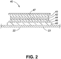
- Fig. 2 is a cross-section of the pressure sensor 40.
- the pressure sensor 40 includes a piezoactive material 42 for converting changes in the application of pressure to the pressure sensor 40 into an electrical signal.
- the piezoactive material 42 is between a first flexible electrode 44 and a second flexible electrode 45.
- a first flexible surface layer 46 is positioned externally to the first flexible electrode 44 and a second flexible surface layer 47 is positioned externally to the second flexible electrode 45.
- a first substrate carrier layer 48 is positioned externally to the first flexible surface layer 46.
- the first substrate carrier layer 48 is connected to the support portion 22 at the sensing portion 23.
- the piezoactive material 42 may include a piezoresistive material (e.g. piezoresistive ink, etc.), a piezocapacitative material (e.g. dielectric glass or other dielectric material, etc.), or a piezoelectric material (e.g. piezoelectric ink, etc.).
- Piezoresistive inks are inks capable of conducting electricity and may include a variety of metals (e.g. copper, silver, gold, graphite or other conductive carbon, or tin oxide or other conductive ceramics, polypyrole or other conducting polymers, or mixtures thereof, etc.).
- piezoactive material 42 includes piezoresistive material
- modulation of the application of pressure to the pressure sensor 40 results in changes to the resistance of the piezoresistive material 42, which in turn results in the signal corresponding to the measured pressure being sent to the processing element 33.
- the flexible electrodes 44, 45 generally include conductive metals, (e.g. copper, silver, aluminum, gold, etc.).
- the first flexible electrode 44 may be manufactured of the same material as the second flexible electrode 45 or of a different material.
- the flexible surface layers 46, 47 support and protect the piezoactive material 42 and flexible electrodes 44, 45.
- the flexible surface layers 46, 47 may be composed of any suitable material (e.g. polyethelene terephthalate (PET), also known as MylarTM, etc.).
- PET polyethelene terephthalate
- MylarTM MylarTM
- the material of the flexible surfaces layers 46, 47 is selected to be an effective insulator and to be compatible with the flexible electrodes 44, 45.
- the substrate carrier layer 48 is prepared from a material that maintains an appropriate elasticity and durometer values and is compatible both with the first flexible surface layer 46 and the sensing portion 23 (e.g. thermoplastic polyurethane for use with a PET flexible surface layers 46, etc.).
- the pressure sensor 40 may be thin (e.g. ranging from about 50 ⁇ m to about 1000 ⁇ m, less than about 200 ⁇ m, etc.).
- the thin and flexible nature of the pressure sensor 40 facilitates conforming to the target surface to which the support web 20 is applied. Substantial conformity with the target surface facilitates measurement of pressure and other biological parameters on non-planar and irregular target surfaces.
- the pressure sensor 40 may be manufactured using a multi-step printing process, allowing for selection of the shape of the pressure sensor 40, which may be round, oval, lobe shaped, wedge shaped, or any other suitable shape.
- the first flexible surface layer 46 may be printed, followed by the first flexible electrode 44, the piezoactive material 42, the second flexible electrode 45, and the second flexible surface layer 47.
- a first portion of the sensor 40 may be fabricated and assembled with a second portion of the sensor 40.
- the first portion may include the first flexible surface layer 46, the first flexible electrode 44, and the piezoactive material 42.
- the second portion may include the second flexible surface layer 47 and the second flexible electrode 45. The first and second portions may then be assembled and mounted onto the support web 20 (see Fig. 1 ).
- Fig. 3 is an exemplary electrical circuit 70 for inclusion into the pressure sensor 40.
- the electrical circuit includes an adjustable sensor resistor 72.
- the adjustable sensor resistor 72 includes the piezoresitive material, which changes resistance in response modulation of the application of pressure to the pressure sensor 40.
- the adjustable sensor resistor 72 is electrically coupled in series between a constant resistor 74 and a ground 75. A voltage is applied between voltage points V in 76 and V out 77. The voltage is applied through a power supply (e.g. a battery, etc.). The applied voltage provides a voltage level defined by the resistors 72, 74 and the amperage of the current. As a result of a modulation in application of force on the piezoresitive material in the piezoactive material 42, the resistance in the adjustable sensor resistor 72 changes, and the voltage between V in 76 and V out 77 changes. This change can be measured and correlated to the modulation of the application of pressure to the pressure sensor 40.
- a power supply e.g. a battery, etc.
- the processing element 33 includes a processor 34 in operative communication with a computer readable memory 35 for accessing information in the computer readable memory 35.
- the processor 34 may include one or more microcontrollers, microprocessors, digital signal processors (DSPs), field programmable gate arrays (FPGAs), application specific integrated circuits (ASICs), or other suitable programmable devices.
- the processor 34 may also be in communication a peripheral devices (e.g. analog-to-digital (A/D) converters, serial or parallel digital input/output devices, other peripheral components or devices, etc.) upstream of the output device 50 (peripheral device not shown).
- the processor 34 accesses a program encoded on a computer readable memory 35 or other circuit for storing instructions for execution on the processor 34, or these instructions may be present on the processor 34.
- the computer readable memory 35 includes a data store in electronic readable format.
- the data store includes a threshold pressure value and other measurement parameters.
- the data store may also include a threshold value for one or more other measured biological parameters.
- the data store may be organized in any suitable manner for storing, accessing, and retrieving data (e.g. databases, tables, files, lists, queues, directories, data storage devices, data serves, data storage media, etc.).
- the computer readable memory 35 may include any storage component configured to be programmed with a value or state and maintain that value or state for access at a later time, and associated hardware and software.
- the computer readable memory 35 may store such value or state in any suitable memory (e.g. random access memory, read only memory (ROM), erasable programmable ROM (EPROM), electronically EPROM, application specific integrated circuit, etc.).
- the processor 34 and the computer readable memory 35 may be positioned peripherally to the input element 32 and the sensing portion 23, and may be positioned peripherally to the support web 20, meaning that the processor 34 and the computer readable memory 35 are coupled to the input element 32, the sensing portion 23, or the support web 20, but separately housed.
- one or both of the processor 34 and the computer readable memory 35 may be physically associated with the support web 20.
- one or both of the processor 34 and the computer readable memory 35 may be separately housed from the support web 20, which facilitates use of a support web 20 manufactured such that the processor 34, the computer readable memory 35, or both, can readily be decoupled from the input device 32 and re-used upon disposal of the support web 20 and input device 32.
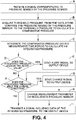
- Fig. 4 is a flowchart of a method for sensing pressure on the target surface.
- the processor 34 accesses and executes computer readable instructions for carrying out the steps of Fig. 4 (e.g. instructions resident on the computer readable memory 35, on the processor 34 itself, at a separate location transmitted wirelessly to the processor 34, etc.).
- the computer readable instructions cause the processor 34 to receive a signal corresponding to pressure sensed by the pressure sensor 40 (Step A), acquire the data corresponding to a threshold pressure value from the data store and compare the pressure in the signal to the to calculate a comparative pressure (Step B).
- the processor 34 integrates the comparative pressure over a measurement time period (e.g.
- Step C 10 minutes, 15 minutes, etc.
- Step C an integrated pressure
- Step D an alert value
- Step E an alert signal is sent to the output device to display or change an alert status
- Step F a change condition
- a change signal is sent to the output device (Step G) and either change a measurement parameter applied by the processing element 33 is changed or an active calibrator 37 is applied to recalibrate the first pressure sensor 40 to a recalibrated pressure range (Step H).
- a signal corresponding to data of the integrated pressure is communicated from the processor 34 to the output device 50 (Step I).
- the computer readable memory 35 includes data corresponding to measurement parameters including at least one threshold pressure value, at least one measurement time period, at least one alert value, and at least one change condition. Data corresponding to a plurality of any of the above measurement parameters may be stored in the computer readable memory 35 (e.g. a plurality of threshold pressure values for computing comparative pressures against different threshold pressure values, a plurality of measurement time periods, a plurality of alert values, a plurality of change conditions).
- the threshold pressure value may be set at various values (e.g. between about 0 and about 80 mm Hg, between about 20 and about 40 mm Hg, between about 25 mm and 35 mm Hg, etc.).
- a threshold pressure value between about 25 mm and 35 mm Hg may facilitate use in the pressure data acquisition assembly 10 for application to a target surface that is not expected to receive substantial external pressure when the patient in normal resting condition.
- Lower threshold pressure values are useful where the target surface is wounded or otherwise sensitive, with higher threshold pressure values being more useful for target surfaces that are more resistant to damage from applied pressure.
- the time period applicable to an integrated pressure may be lowered for comparing the integrated pressure over a smaller time period. This allows monitoring of changes over a shorter time frame, which facilitates monitoring of sensitive target surfaces.
- the comparative pressures reflect, in a quantitative manner, the difference between a measured pressure value and the threshold pressure value.
- the comparative pressure may be relatively simple (e.g. subtraction of the threshold pressure value from the measured pressure value, etc.) or the comparative pressure may be more complex.
- the processor 34 integrates the comparative pressures recorded during a measurement time period, providing an integrated pressure.
- the integrated pressure may be express, for example, as a fraction of the pressure measurements which exceed the threshold pressure value during the measurement time period.
- the processor 34 may be programmed to execute a timer function to measure the total time interval the support web 20 is applied continuously to the target surface.
- the output device 50 would be capable of displaying the total time interval the support web 20 has been applied continuously the target surface.
- an electronic clock may be automatically started upon first application of the support web 20 the target surface, and time kept for the entire duration the support web 20 is kept in place the target surface.
- the time data may be used by a physician or patient to interpret other data relating to the measurement of the pressure or other biological parameter provided by the output device 50.
- a log of pressure changes over time may have application in interpreting the sleep patterns of the individual on whom the target surface is located.
- the processor 34 may further be configured to compute a time period wherein, following a time interval of application of external pressure to the target surface, no external pressure, or no external pressure in excess of the first value, the second value, or the alert value, is applied to said area. Data of the time period wherein no external pressure is applied may be communicated to the output device 50. This may provide data with respect to corrective action that has been taken following an indication that the target surface has received excess pressure.
- An alert value may be defined and stored in the computer readable memory 35.
- the alert value is an integrated pressure value. Where the alert value is equaled or exceeded by the measured integrated pressure value, the processor 34 causes the output device 50 to communicate the alert signal to the user (see Step E in Fig. 4 ). Because the alert value is an integrated pressure value, it can be reached by high pressure readings for a short period of time, or lower pressure readings kept up consistently for a time. The alert value may for example alert individual on whom the target surface is located to mitigate formation of pressure ulcers, or direct turning of the individual by caregivers. Greater integrated pressure values can be used to determine how long and to what extent bloodflow has been restricted and the alert value indicates when pressure should be offloaded. The selected integrated pressure value would be based on the likelihood that further interruption of bloodflow will result in injury.
- the electronic controlling element 30 may be configured to measure pressure on the target surface with a periodicity of 4 Hz, during a time interval of 10 minutes.
- the data store includes a threshold pressure value of 30 mm Hg. If the pressure sensor has delivered 1000 readings exceeding 30 mM Hg to the processor 34 during the time interval, the total number of readings consists of 2400 readings (10 minutes at 4 Hz), while the fraction of readings exceeding the threshold pressure value computed by the processing element is 0.417. A defined fraction of pressure readings exceeding the threshold pressure value could be applied as the alert value, with fractions greater than the alert value resulting in the alert signal from the output device 50. The alert value could, for example, be 90% of measured pressure readings being greater than the threshold pressure value.
- the threshold pressure value is between 35 and 50 mm Hg, and 3600 readings are taken during a 15 minute measurement time period at 4 Hz.
- This combination of measurement parameters is more suited to healthier individuals, or on a less sensitive target surface, than the above example with a 30 mm Hg threshold pressure value and 10 minute measurement time period.
- the alert value can be greater (i.e. through a greater threshold pressure value) and the measurement time period can be longer.
- the processor 34 may be configured to provide different signals to the output device 50 based on the number of comparative pressure measurements exceeding a selected value, the selected value being analogous to the alert value. For example, the processor 34 may direct the output device 50 to send a first signal when the computed fraction of measurements that exceeds the threshold pressure value is lower than a first value (e.g. less than 25%, etc.), a second signal when the computed fraction of measurements that exceeds the threshold pressure value is higher than a second value (e.g. more than 75%, etc.), and the alert signal when the computed fraction of measurements that exceeds the threshold pressure value is greater than the alert value (e.g. more than 90%, etc.).
- a first value e.g. less than 25%, etc.
- a second signal when the computed fraction of measurements that exceeds the threshold pressure value is higher than a second value (e.g. more than 75%, etc.)
- the alert signal when the computed fraction of measurements that exceeds the threshold pressure value is greater than the alert value (e.g.
- the output device 50 may be configured for immediate communication to a patient, physician or caregiver of an alert signal upon occurrence of an aggravating event to the target surface, facilitating timely intervention.
- a user may select a particular measurement parameter (e.g. a selected threshold pressure, time measurement period, alert value, or change condition). Similarly, the user may direct the active calibrator 37 to recalibrate the pressure sensor 40 to a recalibrated pressure range.
- a user may select an appropriate threshold pressure value, alert value, and measurement time period, and may recalibrate the pressure range when applying the support web 20 to the target surface.
- the user may select appropriate mild conditions (e.g. lower threshold pressure values, lower alert values, shorter measurement time periods etc.), and recalibrate the pressure sensor 40 to a lower pressure range, for sensitive target surfaces or use on individuals with poor circulation, etc.
- the user may select appropriate more severe conditions (e.g. higher threshold pressure values, higher alert values, longer measurement time periods etc.), and recalibrate the pressure sensor 40 to a higher pressure range, for target surfaces in good condition or use on target surfaces which are more robust.
- the processor 34 may also direct a measurement parameter to change, or direct the active calibrator 37 to recalibrate the pressure sensor 40 to a different pressure range, in response to a change condition being met. For example, where a long period of alert values or other high integrated pressure values is sensed, the alert values may be lowered (or the threshold pressure values may be lowered, resulting in lowered alert values), or the time measurement period may be shortened. Similarly, the active calibrator 37 may be directed to recalibrate the pressure sensor to a pressure range with lower values. Each of these changes would result in an assembly 10 which responds to lower pressures.
- the processor 34 may decrease the time measurement period (e.g. to 5 minutes, 1 minute, etc.) and increase the measurement frequency (e.g. to 20 Hz, 100 Hz, etc.) if it detects that the integrated pressure is changing rapidly, which may indicate movement of the individual, justifying increasing the sensing frequency.
- the time measurement period e.g. to 5 minutes, 1 minute, etc.
- the measurement frequency e.g. to 20 Hz, 100 Hz, etc.
- the assembly 10 may change measurement parameters of the pressure sensor 40 to increase the pressure threshold value, the alert value, or the measurement time period, or recalibrate the pressure range to a higher recalibrated pressure range, each of which allows less sensitive monitoring of pressure for healthier tissue.
- the processor 34 may direct changes in measurement parameters to allow the assembly 10 to generate alert signals only with relatively high integrated pressures.
- the processor 34 directs the active calibrator 37 to recalibrate the pressure range to a higher recalibrated pressure range.
- the processor 34 may cause the active calibrator 37 to direct recalibration to a lower recalibrated pressure range.
- the processor 34 may cause the active calibrator 37 to direct recalibration to a higher recalibrated pressure range.
- the active calibrator 37 recalibrates the pressure range to match the pressures being sensed after turning.
- the output device 50 is operably coupled to the processor 34 for receiving data from the processor 34.
- the output device 50 includes a communication element 52 which receives a signal corresponding to the comparative pressure, the alert signal, the first signal, the second signal, or a signal with other data, from the processor 34, for display and communication to the user.
- the communication element 52 is shown as including an LED bulb.
- the LED bulb communication element 52 can turn on or flash when the comparative pressure exceeds the threshold pressure value, when the alert signal is otherwise received, or on other conditions.
- the communication element 52 could include a speaker or other suitable device which can communicate the above conditions.
- Calibration may be passive or active. With passive calibration, the pressure sensor 40 is calibrated to be operable within a certain pressure range, and the range remains constant.
- the circuit 70 provides passive calibration to pressure sensor 40.
- the adjustable sensor resistor 72 is permanently calibrated at the time of manufacture to operate in a selected range of pressures.
- the adjustable sensor resistor 72 may operate in a pressure range varying from about 20 mm to about 30 mm Hg, from about 30 to about 40 mm Hg, from about 40 Hg to about 50 mm Hg, from about 50 mm to about 60 mm Hg, from about 60 mm Hg to about 70 mm Hg, or from about 70 mm Hg to about 80 mm Hg.
- broader ranges may be applied (e.g. from about 35 mm Hg to about 50 mm Hg, from about 30 mm Hg to about 55 mm Hg, from about 30 mm Hg to about 60 mm Hg, or other ranges of about 25 or 30 mm Hg, etc.).
- the electronic controlling element 30 includes an active calibrator 37 for calibrating the pressure sensor 40 to sense pressure within a selected pressure range. Active calibration allows changes to the pressure range within which the pressure sensor 40 senses pressure, facilitating measurement of substantial variations in the magnitude of the pressures sensed by the pressure sensor 40.
- Active calibration facilitates accounting for variations in topical skin pressures on the target surface, which may vary considerably. For example, pressure exerted on a sole of a foot in an upright standing condition is substantially higher than pressure experienced on most surface areas of a torso in normal resting condition. Active calibration facilitates using the same pressure data acquisition assembly 10 on both surfaces.
- the sensing portion 23 of the support web 20 includes multiple pressure sensors 40 (or multiple sensor elements 360 per Fig. 10 below), different pressures may be sensed at different portions of the sensing portion 23. Such local variations in pressure are particularly likely on relatively non-stationary areas of the skin (e.g. where portions of the skin cover joint areas, where due to movement temporal changes in pressure are experienced, etc.).
- the pressure range which is sensed by the pressure sensor 40 can be adjusted on an as-needed basis by the user, for example as part of the process of applying the support web 20, at defined time intervals (e.g. every 30 minutes, etc.), or when a change status occurs (i.e. when a change condition has been met).
- Fig. 5 is an electrical circuit 170 which provides active calibration and could be applied in the active calibrator 37.
- the electrical circuit 170 shares many features of the electrical circuit 70, and reference numerals in Fig. 5 including the same two digits as reference numerals in Fig. 3 have the same labels for those reference numerals.
- the voltage at V out 177 is defined by the adjustable sensor resistor 172, an adjustable calibration resistor 178, and the amperage of the current. Changing the resistance of the adjustable calibration resistor 178 adjusts the range of changes in resistance of the adjustable sensor resistor 172 which result in a detectable change in potential at V out 177.
- a user or the processor may set the resistance of the adjustable calibration resistor 178, thereby selecting the range in which the pressure is measured.
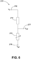
- Fig. 6 is an electrical circuit 270 which provides active calibration and could be applied in the active calibrator 37.
- the electrical circuit 270 shares many features of the electrical circuit 70, and reference numerals in Fig. 6 including the same two digits as reference numerals in Fig. 3 have the same labels for those reference numerals.
- the voltage at V out 277 is defined by the adjustable sensor resistor 272, the constant resistor 274, the amperage of the current, and an applied reference voltage V ref 279.
- Changing the applied reference voltage V ref 279 adjusts the range of changes in resistance of the adjustable sensor resistor 272 which result in a detectable change in potential at V out 277.
- a user or the processor 34 may set the reference voltage V ref 279, thereby selecting the range in which the pressure is measured.
- Each of the circuits 170, 270 allows selection of a pressure range in which the pressure is measured. The pressure is compared to the threshold pressure value to determine the comparative pressure, allowing pressure sensors with which the circuits 170, 270 are used to be applied to different pressure ranges.
- the active calibrator 37 is coupled to the pressure sensor 40 and may be housed or co-located in the processing element 33 with the processor 34 and computer readable medium 35 (as shown in Fig. 1 ), co-located with the pressure sensor 40, or located elsewhere (see calibrator 237 in Fig. 8 ).
- the active calibrator 37 facilitates use of the support web 20, upon calibration, on any or substantially any target surface of a user or animal, regardless of the conditions at the target surface at the target surface (e.g. joints or other moving tissue, bony prominences, etc.).
- the active calibrator 37 facilitates sensing pressure on target surfaces with substantial positional or temporal pressure variability (e.g. for use on target surfaces such as skin covering joints or other bony prominences, etc.).
- the active calibrator 37 may be more suitable where reuse of the pressure data acquisition assembly 10, the electronic controlling portion 30, or the input element 34, is intended.
- the electronic controlling portion 30, or input element 34 may apply passive calibration only (i.e. having the circuit 70 as opposed to the circuits 170 or 270, and lacking the calibrator 37 as in the bandage and pressure data acquisition assembly 111 of Fig. 7 ).
- the support web 20 may be removable from the electronic controlling portion 30, sensor 40, and output device 50.
- the pressure sensor 40 may be directed by the processor 34 to repeatedly and periodically measure pressure during a measurement time period (e.g. at least 1 minute, at least 5 minutes, at least 10 minutes, at least 15 minutes, at least 30 minutes, 15 minutes, etc.).
- the pressure sensor 40 may be directed by the processor 34 to, upon completion of a first series of measurements during a first time interval, initiate a second series of measurements during a second time interval.
- the initiation of the second series of measurements may occur automatically (e.g. on a regular basis, irregular basis, as a result of a condition being satisfied, etc.) or through manual initiation by a user.
- the pressure data acquisition assembly 10 may continuously or substantially continuously monitor the target surface.
- the periodicity with which pressure is measured may be regular or irregular.
- the periodicity of the measurements may vary (e.g. between 0.5 Hz and 100 Hz, between 0.5 Hz and 25 Hz, etc.).
- Relatively high frequencies of pressure measurements e.g. 100 Hz, etc.
- Lower frequencies may be applied where there is less movement, for example a bedridden patient.
- Higher frequencies are often used during calibration by the active calibrator 37 while the target surface is immobile to calibrate in a shorter period of time.
- the processing element 33 may send a signal indicating that calibration is occurring to the output device 50 for display.
- the data obtained may be made available on a substantially real-time basis to a patient, physician, caregiver or other user, without requiring direct visual inspection of the surface area.
- Fig. 7 shows a bandage and pressure data acquisition assembly 111.
- the bandage and pressure data acquisition assembly 111 shares many features of the data acquisition assembly 110, and reference numerals in Fig. 7 including the same two digits as reference numerals in Fig. 1 have the same labels for those reference numerals.
- the support web 120 is a bandage and includes the support portion 122, a treatment portion 124, and an adhesive portion 126.
- the support portion 122 provides a support substrate for the treatment portion 124.
- the treatment portion 124 overlaps with the sensing portion 123, with the treatment portion 124 being larger than the sensing portion 123 in the bandage 120.
- the treatment portion 124 provides a suitable surface for contacting the target surface where the skin has compromised integrity or is otherwise sensitive.
- the treatment portion 124 may be prepared from a wide variety of materials, both natural and synthetic, that are compatible with such application. Suitable materials include one or more layers of a textile material, non-woven fabric, foam, fiber or fibrous materials, for example cotton, or biocompatible polymeric materials, such as polyethylene terepthalate, polypropylene, or blends of viscose rayon and polyolefins.
- the treatment portion 124 may be constructed from one or more layers of fiber gauze or other materials for providing cushioning and absorbing wound exudates.
- the adhesive portion 126 includes an adhesive for adhering and securing the bandage 120 to the target surface in a manner that substantially follows the contours of the user and substantially conforms to the surface of the skin at the target surface.
- the adhesive may be a glue, glue-like substance, pressure acrylic adhesive or any other material.
- the adhesive portion 126 substantially conforms to the target surface and adheres the treatment portion 124 to the target surface.
- the support web 20, or other embodiments lacking the adhesive portion 126, may be secured to the target surface by tape or other means that are separate from the support web 20.
- the output device 150 includes a first output module 154 which communicates a signal corresponding to the comparative pressures value received from the processor 134 to a second output module 156.
- the second output module 156 receives the comparative pressure from the first output module 156 for display on a communication element 152.
- the communication element 152 is shown as including a screen on a tablet. Similarly the communication element 152 could be a screen on a different device or any suitable display, for example as described above. Communication between the first output module 154 and the second communication module 156 is shown as being through a wireless connection 155, but any suitable connection can be used.
- the second output module 156 and the communication element 152 are positioned peripherally to the bandage 120.
- the processor 134, the computer readable memory 135, and active calibrator 137 may conveniently be assembled and co-housed with the sensor 140 or with the first output module 154.
- the processor 134, computer readable memory 135, and active calibrator 137 may be co-located with the bandage 120 or located peripherally to the bandage 120.
- the communication element 152 displays the comparative pressure or derivatives thereof (e.g. the fraction of the plurality of measured pressure values that exceeds the threshold pressure, etc.).
- the output device 150 may include any suitable device for displaying the comparative pressure (e.g. a TV screen, LCD, LED backlit screen, a computer screen, a tablet screen, a smartphone screen, a three-dimensional display, a printer, a USB key or other electronic storage device, etc.).
- the output device 50 may display the comparative pressure in different ways (e.g. auditory, numerically, graphically, etc.).
- Graphical displays may include various graphs (e.g. pie-chart, bar graph, a graphical representation of the target area, etc.).
- Figs. 8 and 9 show an alternative bandage and pressure data acquisition assembly 211.
- the bandage and pressure data acquisition assembly 211 shares many features of the data acquisition assembly 110, and reference numerals in Figs. 8 and 9 including the same two digits as reference numerals in Figs. 1 and 2 have the same labels for those reference numerals.
- the bandage 220 has a heart shape, including at the supportive portion 222, sensing portion 223, treatment portion 224, and adhesive portion 226. In addition to the heart shape of the bandage 220 and the substantially rectangular shapes of the support web 20 and bandage 120 (see Figs. 1 and 7 ), any suitable shape may be applied (e.g., oval-shaped, heart-shaped. etc.).
- the sensor 240 includes a protective second substrate carrier layer 249 externally to the second flexible surface layer 247.
- the second substrate carrier layer 249 provides resistance to abrasion of the sensor 240 by protecting the second flexible surface layer 247.
- the second substrate carrier layer 249 may be made from the same material as the first substrate carrier layer 248 (e.g. PET, etc.) or of a different material.
- the second substrate carrier layer 248 would be prepared from a material selected to protect (e.g. from delamination, etc.) and be compatible with the second flexible surface layer 247, but unlike the first substrate carrier layer 248, need not be compatible with the sensing portion 223 and treatment area 224.
- the second substrate carrier layer 249 may also be selected to maintain the correct durometer, elasticity, and resilience in the face of pressures and temperature changes. This mitigates the potential for higher or prolonged pressures, or increased temperatures, to affect calibration of the pressure sensor 240.
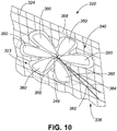
- Fig. 10 shows the sensing portion 323 of a support web 320.
- the pressure sensor 340 includes six circumferentially positioned lobe-shaped sensor elements 360 connected to the sensor support layer 348.
- the sensor support layer 348 is connected to the treatment portion 324.
- the first connection 336 includes electrical leads 362 and 364 for respectively providing input to and receiving output from the pressure sensor elements 360.
- the electrical lead 362 provides power to the pressure sensor elements 360 and the electrical lead 364 receives signals corresponding to changes in pressure on the sensor elements 360 (e.g. a change in voltage across a circuit where the pressure sensor elements 360 include a piezoresistive material, etc.).
- Electrical leads 368 connect the sensor elements 360 to the electrical leads 362 and 364. Where the pressure sensor elements 360 are circumferentially spaced, a circumference 368 is defined around the pressure sensor 340.
- each sensor element 360 may generate a separate signal for transmission of individual pressure measurements, or only the sensor element 360 with the greatest signal strength at a given time point will send a transmission, etc.
- the sensor 340 includes six lobe-shaped sensor elements 360.
- sensor elements may have other shapes and may be present in other numbers (e.g. 3, 4, 5, 6, 7, 8, 9, or 10 sensor elements, etc.).
- Fig. 11 shows a pressure data acquisition assembly 410 wherein the support web 420 includes a sensor array 480 shaped for adhering to a sacrum.
- the pressure data acquisition assembly 410 shares many features of the data acquisition assembly 10, and reference numerals in Fig. 11 including the same two digits as reference numerals in Fig. 1 have the same labels for those reference numerals.
- the sensor array 480 includes eight sensors 440 arranged for application to a sacral area of a user, although other sensor arrays could be prepared with two or more sensors (e.g. 3, 4, 5, 6, 7, 8, 9, 10, etc.).
- the sensors 440 may be substantially identical in shape, size and electronic configuration, or individual sensors 440 may have a different shape, size or electronic configuration.
- the sensor array 480 may facilitate treatment or prevention of pressure-based injuries on non-planar or irregular surfaces compared to use of a support web having only one sensor (e.g. the support web 20, or bandages 120, 220 of Figs. 1 , 7 , and 8 ), for example target surfaces comprising a bony protrusion, where due to the non-planar or irregular shape of the target surface, different portions of the target surface areas are subject to different pressures.
- the support web 420 is flexible and conforms to the target area.
- the sensors 440 in the array 480 are shown as sharing a common first substrate carrier layer 448.
- the sensors in the array 480 may alternatively have individual first substrate carrier layers which do not overlap (not shown).
- the individual sensors 440 may be calibrated to the same measured pressure range or different ranges.
- the processor 434 may be configured to apply signals from all different pressure sensors 440 to the output shown by the output device 450 equally. Alternatively, the processor 434 may be configured to apply signals from different pressure sensors 440 to the output shown by the output device 450 differently. For example, the processor 434 may be configured to provide the alert signal when 50% of the measured input parameters measured by a first pressure sensor 441 exceed the alert value, or when 75% of the measured input parameter measured by a second pressure sensor 443 exceeds the threshold pressure value. For example, the first and second pressure sensors 441, 443 could have different threshold pressure values assigned to them.
- the processor 434 may confirm that both the first pressure sensor 441 and the second pressure sensor 443 are experiencing similar pressure readings. If this is confirmed, the first pressure sensor 441 will be recalibrated. If not, the processor will interpret this as a malfunction (e.g. due to the first or second pressure sensors 441, 443 becoming detached form the individual, etc.) and send an alert signal.
- the second pressure sensor 443 would be located on the individual outside of the target surface. In this example, the second pressure sensor 443 may be excluded from the grouping algorithm (see below) and used only as a reference for the first pressure sensor 441 and other pressure sensors 440.
- the processor 434 may be configured in such a manner that data acquired from each individual pressure sensor 440 is provided to the output device 450, so that individual pressure sensors 440 can be tracked on the output device 450.
- the processor 434 and output device 450 may represent data of one or more pressure sensors 440 grouped in accordance with a grouping algorithm.
- the grouping algorithm may be applied by the processor 434 and then provided to the output device 450, or may be applied by the output device 450.
- the data from each pressure sensor 440 may be treated equally, or a varying weighting may be applied to each data set depending on which sensor the data is acquired from (e.g. as described above with respect to the first and second pressure sensors 441, 443 having different threshold pressure values or different percentages of measurements above the threshold pressure value to trigger an alert, etc.).
- the calibrator 437 is in communication with the pressure sensors 440 to calibrate some or all of the pressure sensors 440.
- the calibrator 437 may calibrate the pressure sensors 440 together, in groups, or individually.
- the calibrator 437 may calibrate the pressure sensors 440 with different pressure ranges or the substantially similar pressure ranges.
- the calibrator 437 may include several individual calibrators (not shown), each for one or more of the pressure sensors 440.
- the calibrator 437 and the pressure sensors 440 may be in communication with each other to direct calibration throughout the sensor array 480.
- the first pressure sensor 441 may be calibrated to a pressure range applicable to the second pressure sensor 443, or to all other pressure sensors 440.
- the first pressure sensor 441 may be directed by the processor 434 to recalibrate the second pressure sensor 443, or all the pressure sensors 440, at a recalibration frequency (e.g. every 30 minutes) or upon a change status occurring.
- the alert value of the second pressure sensor 443 may change.
- the first and second pressure sensors 441, 443 may be controlled by the same electronic control element 430 as shown or by different electronic control elements (not shown).
- pressure sensor array 480 may have an analogous relationship where a first pressure sensor array 480 calibrates a second pressure sensor cluster 480 (not shown).
- Fig. 12 is a schematic of a graphical display 482 on the communication element 452.
- a target area 484 of the sensor array 480 corresponding to an individual's sacrum is displayed schematically. Portions of the target area in relation to which signals of different integrated pressures are being displayed by the output device 450 are shown with a color coded scheme. For example, a first color 481 if less than 25% of the comparative pressures exceed the alert value during the measurement time period, a second color 483 if between 25% and 50% of the comparative pressures exceed the alert value during the measurement time period, and a third color 485 for the alert status where more than 90% of the comparative pressures exceed the alert value.
- the third color 485, may be emphasized (e.g. by flashing, repetitive changes in color during display, etc.).
- the processor 434 may cause the communication element 452 to display a graphical representation of the target surface and integrated pressures with the first color 481 if less than 35% of the comparative pressures exceed the alert value during the measurement time period, the second color 483 if between about 35% and 90% of the comparative pressures exceed the alert value during the measurement time period, and the third color 485 if more than about 90% of the comparative pressures exceed the alert value during the measurement time period.
- the comparative pressures may also be displayed, directly or indirectly, with each of the colors 481, 483, and 485 is displayed to reflect different comparative pressures (not shown).
- the graphical display 482 can be used to assess progress of wound healing and to provide diagnostic information helpful to decisions as to patient adjustment, turning regimens, and other applications.
- the sensor array 480 includes a first biological parameter sensor 488 and a second biological parameter sensor 489, each for sensing a value of a biological parameter on the sensing surface 423.
- Biological parameters are features at the target surface other than pressure which are relevant to diagnostic or other useful information, or which affect performance of the pressure sensors 440.
- Biological parameters include, for example, temperature, pH, bacterial load, or humidity of the target surface, and muscle activity (e.g. measured through electromyography, etc.), etc.
- Data of biological parameters may be integrated over time and compared to a biological parameter alert value or biological parameter change condition.
- the first and second biological parameter sensors 488, 489 sense biological parameters on different areas of the sensing surface 423.
- the first and second biological parameter sensors 488, 489 may sense the same biological parameters or different biological parameters.
- the computer readable memory 435 may be configured to store threshold biological parameter values, and the processor 434 may be configured to calculate comparative biological parameter values based on threshold biological parameter values.
- the biological parameter sensors 488, 489 may include variable resistance circuits similarly to the electric circuit 70, and the active calibrator 437 may set a range within which biological parameters are measured through circuits similar to the electrical circuits 170, 270. However, some biological parameters in some cases display absolute values which may not benefit from active calibration (e.g. temperature, moisture, etc.).
- the output device 450 may communicate comparative biological parameter values based on first, second, or alert signals similarly to the corresponding signals for comparative pressures.
- the biological parameter values may affect how the processor 434 processes the comparative pressures and integrated pressures, may direct the processor 434 to reapply the calibrator 437 to some or all of the pressure sensors 440 for recalibration, alter the first, second, or alert values of one of more of the sensors 440, or otherwise affect sensing, processing, or display of data.
- the first, second, or alert values may be shifted to lower integrated pressures.
- this may be an indicator of poor wound healing, which could result from excessive pressure on the wound, and suggest that the individual on whom the support web 420 is placed turn more frequently or change position, or that the first, second, or alert values be lowered for some or all sensors 440.
- integrated temperature values above the applicable change condition result in the processor 434 activating the calibrator 437 to recalibrate the pressure range of some or all of the pressure sensors 440, and change the pressure threshold values and alert values, as the materials the support web 420 is made from may be affected by the heat.
- a spike in integrated temperature values suggests that active healing is occurring at the target surface and the threshold pressure values, alert values, and measurement time periods are all decreased. This provides milder, lower pressure conditions for the healing to continue.
- pH may be an indicator of bacterial load, which may delay or otherwise impede healing of a wound.
- the effect of moisture is context dependent, with high moisture in some circumstances promoting epithelial cell migration and healing, and in other circumstances, impeding healing.
- a user would be able to select which relationship between moisture and the measurement parameters applies in this case.
- Muscle activity which may be measured by electromyography or other methods, provides information related to where and how much movement has been occurring on the target surface.
- the support web 420 includes a feedback element 490 in communication with the processor 434.
- the processor 434 may direct the feedback element 490 to take an action with respect to the individual on whom the target surface is located.
- the action may be directed to reduce pressure or otherwise improve conditions at the target surface, or provide sensing data otherwise useful for diagnosis.
- the action may be taken in response to an alert status or change status (based on pressure data or biological parameter data).
- the feedback elements may for example provide vibration, heat, transcutaneous electrical nerve stimulation or other muscle stimulation, modification of moisture levels, inflation of air bladder pockets, administration of antibiotics or other drugs, or other stimulus or action.
- the feedback element may decrease or increase pressure in the bed by deflating or inflating air pockets, or may signal the individual in the bed (and on whom the target surface is located) to do the same through a manual control.
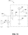
- Fig. 13 is an electrical drain circuit 371 including a current time measurement unit 392 for use with the pressure sensors 40, 140, 240, 340, and 440 or biological parameter sensors 488, 489.
- the electrical drain circuit 371 shares many features of the electrical circuit 70, and reference numerals in Fig. 13 including the same two digits as reference numerals in Fig. 3 have the same labels for those reference numerals.
- the current time measurement unit 392 facilitates sensing pressure values over a greater range.
- the current time measurement unit 392 includes a low resistance resistor 394 connected in series to the adjustable sensor resistor 372 by a switch 395.
- measurements received by the pressure or other biological parameter sensor the electrical drain circuit 371 is operating with may have a drop in frequency.
- the switch 395 will close, lowering the overall impedance of the electrical drain circuit 371 by including the low resistance resistor 394 in the circuit.
- the processor with which the electrical drain circuit 371 is used e.g. processors 34, 134, 234, or 434, etc.
- the processor may also change the threshold pressure value or other biological parameter value in response to the switch 395 closing.
- the switch 395 would be absent and the low impedance resistor 394 permanently included in a circuit to increase the frequency of pressure value measurements to bias for certain measurement ranges (e.g. where high resistance values are expected in the circuit, etc.).
- the current time measurement unit 392 includes a reference capacitor 396 to provide a charging time reference to the current time measurement unit 392.
- the charging time reference is used by the current time measurement unit 392 as a comparator.
- An adjustable current source 397 and drain switches 398, 399 are also in the current time measurement unit 392 to drain current from the circuit 370 before closing the switch 395 to bias the resistance range of the adjustable sensor resistor 372.
- the current time measurement unit 392 also includes a multiplexer 393 for allowing multiple pressure or biological parameter sensors to be in communication with the current time measurement unit 392.
- the current time measurement unit 392 itself may direct draining the circuit 370 and closing the switch 395, or the processor may direct the current time measurement unit 392 to operate these functions.
- the support web 20 may be used to apply to one or more external target surface on the body, including skin that is wounded, injured, or prone to injury, etc.
- the present disclosure includes a method employing the pressure data acquisition assembly 10 for treating or preventing injury of an external surface area of a human body.
- the present disclosure includes use of the pressure data acquisition assembly 10 in the treatment or prevention of injury to an external surface area of the body.
- the pressure data acquisition assembly 10 facilitates monitoring of individuals whose peripheral sensory perception is compromised. Such patients experience, or are prone to experience, unchecked pressure, which may lead to complications including focal ischemia, venous injury, pressure necrosis, ulceration, and in the worst cases, infection and gangrene. Through use of the pressure data acquisition assembly 10, such injuries may be mitigated, prevented, or treated. In addition, the pressure data acquisition assembly 10 may facilitate the treatment of patients lacking normal mobility (e.g. bedbound patients, wheelchair patients, sedated patients, amputees, etc.). The pressure data acquisition assembly 10 may be used both for inpatient and outpatient care. Patients that may include diabetic patients, and patients suffering from ulcers (e.g. decubitus ulcers, etc.). The pressure data acquisition assembly 10 may facilitate prevention of injury (primary prevention), mitigation of injury recurrence (secondary prevention), and/or treatment of a wound or injury (tertiary prevention).
- the data acquired using the pressure data acquisition assembly 10 may be used by the patient, a physician, medical personnel, caregiver or any other user to prevent injury to the skin or underlying tissue, take corrective action or treat an injury or wounded portion of the body.
- the adhesive portion 126 of the bandage 120 which is arranged to adhere the bandage 120 to the external surface area of the body (e.g. the scalp, sacrum, scapula, elbows, knees, greater trochanter, ischial tubersosity, include lower and upper extremity stumps in amputees, etc.).
- Embodiments of the disclosure can be represented as a computer program product stored in a machine-readable medium (also referred to as a computer-readable medium, a processor-readable medium, or a computer usable medium having a computer-readable program code embodied therein).
- the machine-readable medium can be any suitable tangible, non-transitory medium, including magnetic, optical, or electrical storage medium including a diskette, compact disc read only memory (CD-ROM), memory device (volatile or non-volatile), or similar storage mechanism.
- the machine-readable medium can contain various sets of instructions, code sequences, configuration information, or other data, which, when executed, cause a processor to perform steps in a method according to an embodiment of the disclosure.
- At least some of the elements of the various electronic controlling elements described herein are implemented via software and may be written in a high-level procedural language such as object oriented programming or a scripting language. Accordingly, the program code may be written in C, C++ or any other suitable programming language and may comprise modules or classes, as is known to those skilled in object oriented programming. Alternatively, at least some of the elements of the various electronic controlling described herein that are implemented via software may be written in assembly language, machine language or firmware. In either case, the program code can be stored on a storage media or on a computer readable medium that is readable by a general or special purpose electronic device having a processor, an operating system and the associated hardware and software that implements the functionality of at least one of the embodiments described herein. The program code, when read by the electronic device, configures the electronic device to operate in a specific and defined manner in order to perform at least one of the methods described herein.
- the methods described herein include methods are capable of being distributed in a computer program product comprising a transitory or non-transitory computer readable medium that bears computer usable instructions for one or more processors.
- the medium may be provided in various forms such as one or more diskettes, compact disks, tapes, chips, USB keys, external hard drives, wire-line transmissions, satellite transmissions, internet transmissions or downloads, magnetic and electronic storage media, digital and analog signals, tablet or smartphone apps, and the like.
- the computer useable instructions may also be in various forms, including compiled and non-compiled code.
Landscapes
- Health & Medical Sciences (AREA)
- Life Sciences & Earth Sciences (AREA)
- Physics & Mathematics (AREA)
- Surgery (AREA)
- General Health & Medical Sciences (AREA)
- Engineering & Computer Science (AREA)
- Biomedical Technology (AREA)
- Heart & Thoracic Surgery (AREA)
- Medical Informatics (AREA)
- Molecular Biology (AREA)
- Biophysics (AREA)
- Animal Behavior & Ethology (AREA)
- Pathology (AREA)
- Public Health (AREA)
- Veterinary Medicine (AREA)
- General Physics & Mathematics (AREA)
- Dentistry (AREA)
- Oral & Maxillofacial Surgery (AREA)
- Dermatology (AREA)
- Measuring And Recording Apparatus For Diagnosis (AREA)
- Measuring Fluid Pressure (AREA)
Claims (18)
- Druckdaten-Erfassungsanordnung (10), umfassend:ein Stützgewebe (20) zur Auflage auf einer Zieloberfläche eines Körpers einer Person;einen ersten Drucksensor (40), mit dem Stützgewebe (20) verbunden zum Abtasten einer ersten Frequenz eines ersten, auf der Zieloberfläche beaufschlagten Drucks;einen Kalibrator (37) in operativer Kommunikation mit dem ersten Drucksensor (40) zum Kalibrieren des ersten Drucksensors (40) auf einen ersten Druckbereich, in dem der erste Drucksensor (40) den ersten Druck abtastet;ein Verarbeitungselement (33) in operativer Kommunikation mit dem ersten Drucksensor (40) zum Empfangen erster Drucksignale, die Werten des ersten Drucks von dem ersten Drucksensor (40) bei der ersten Frequenz entsprechen, und mit dem Kalibrator (37) zum Neukalibrieren des ersten Drucksensors (40); undeine Ausgabeeinrichtung (50) in Kommunikation mit dem Verarbeitungselement (33) zum Empfangen von Signalen, umfassend Daten von dem Verarbeitungselement (33), und zum Anzeigen der Daten;dadurch gekennzeichnet, dass das Verarbeitungselement (33) umfasst:einen rechnerlesbaren Speicher (35) zum Speichern von Messparametern, umfassend einen ersten Schwellenwert, der einem ersten Schwellenwertdruck entspricht, sowie einen ersten Messzeitraum, einen ersten Alarmwert und eine erste Änderungsbedingung; undeinen Prozessor (34) in operativer Kommunikation mit dem rechnerlesbaren Speicher (35) zum Zugriff auf die Messparameter zum Vergleich des ersten Drucks mit dem ersten Schwellenwertdruck, um einen ersten Vergleichsdruck bereitzustellen, der die Differenz zwischen dem ersten Druck und dem ersten Schwellenwertdruck in einer quantitativen Weise wiedergibt und den ersten Vergleichsdruck über den ersten Messzeitraum integriert, um einen ersten integrierten Druck bereitzustellen, und den ersten integrierten Druck mit dem ersten Alarmwert vergleicht, um einen ersten Alarmstatus zu ermitteln, wobei der erste integrierte Druck mit der ersten Änderungsbedingung verglichen wird, um einen ersten Änderungsstatus zu ermitteln, und zum Neukalibrieren des ersten Drucksensors (40) auf einen ersten neu kalibrierten Druckbereich gemäß dem ersten Änderungsstatus.
- Anordnung nach Anspruch 1, ferner umfassend einen zweiten Drucksensor (443) zum Abtasten eines zweiten, an der Zieloberfläche beaufschlagten Drucks bei einer zweiten Frequenz;
wobei der Kalibrator (37) ferner mit dem zweiten Drucksensor (443) zum Kalibrieren des zweiten Drucksensors (443) in operativer Kommunikation ist;
das Verarbeitungselement (33) mit dem zweiten Drucksensor (443) zum Empfangen von zweiten Drucksignalen, die Werten des zweiten Drucks von dem zweiten Drucksensor (443) bei der zweiten Frequenz entsprechen, und mit dem Kalibrator (37) zum Neukalibrieren des zweiten Drucksensors (443) in operativer Kommunikation ist;
die Messparameter ferner einen zweiten Schwellenwert umfassen, der einem zweiten Schwellenwertdruck entspricht, sowie einen zweiten Messzeitraum, einen zweiten Alarmwert und eine zweite Änderungsbedingung;
das Verarbeitungselement (33) ferner ausgelegt ist zum Vergleichen des zweiten normalisierten Drucks mit einem zweiten Schwellenwert-Druckwert, um die Differenz zwischen dem zweiten Druck und dem zweiten Schwellenwertdruck in einer quantitativen Weise wiederzugeben;
der Prozessor (34) zum Zugriff auf die Messparameter in operativer Kommunikation mit dem rechnerlesbaren Speicher (35) steht, wobei der zweite Druck mit dem zweiten Schwellenwertdruck verglichen wird, um den zweiten Vergleichsdruck bereitzustellen, wobei der zweite Vergleichsdruck mit der Zeit über den zweiten Messzeitraum integriert wird, um einen zweiten integrierten Druck bereitzustellen, und den zweiten integrierten Druck mit dem zweiten Alarmwert vergleicht, um einen zweiten Alarmstatus zu ermitteln, und den zweiten integrierten Druck mit der zweiten Änderungsbedingung vergleicht, um einen zweiten Änderungsstatus zu ermitteln, und mindestens einen Messparameter ändert oder gemäß dem zweiten Änderungsstatus eine Neukalibrierung vornimmt von mindestens einem von: dem ersten Drucksensor (40) zu einem ersten neu kalibrierten Druckbereich und dem zweiten Drucksensor (443) zu einem zweiten neu kalibrierten Druckbereich. - Anordnung nach Anspruch 2, wobei die Daten Daten der ersten und zweiten Vergleichsdrücke und die jeweiligen Positionen des ersten Drucksensors (40) und des zweiten Drucksensors (443) auf dem Zielbereich umfassen und die Daten visuell angezeigt werden.
- Anordnung nach Anspruch 2, wobei die erste Frequenz und die zweite Frequenz im Wesentlichen gleich sind.
- Anordnung nach Anspruch 2, wobei der erste Druckbereich und der zweite Druckbereich im Wesentlichen gleich sind.
- Anordnung nach Anspruch 2, wobei der Kalibrator (37) zum Kalibrieren des ersten Drucksensors (40) und des zweiten Drucksensors (443) mit einem einzelnen Eingabevorgang dient.
- Anordnung nach Anspruch 2, wobei der erste Neukalibrierungsdruckbereich und der zweite Neukalibrierungsdruckbereich im Wesentlichen gleich sind.
- Anordnung nach Anspruch 2, wobei der erste Schwellenwertdruck und der zweite Schwellenwertdruck im Wesentlichen gleich sind.
- Anordnung nach Anspruch 1, ferner umfassend einen mit dem Stützgewebe (20) verbundenen Sensor (448) biologischer Parameter zum Abtasten eines biologischen Parameters der Zieloberfläche bei einer Frequenz biologischer Parameter;
wobei
das Verarbeitungselement (33) mit dem Sensor (488) biologischer Parameter in operativer Kommunikation steht, um Signale biologischer Parameter in einem Wertebereich biologischer Parameter zu empfangen, der Werten biologischer Parameter bei der Frequenz biologischer Parameter entspricht;
die Messparameter ferner einen biologischen Schwellenwert umfassen, der einem Schwellenwert biologischer Parameter entspricht, sowie einen Messzeitraum biologischer Parameter, einen Alarmwert biologischer Parameter und eine Änderungsbedingung biologischer Parameter; und
der Prozessor (34) zum Zugriff auf die Messparameter in operativer Kommunikation mit dem rechnerlesbaren Speicher (35) steht, wobei die Werte der biologischen Parameter mit dem Schwellenwert biologischer Parameter verglichen werden, um einen Vergleichswert biologischer Parameter bereitzustellen, wobei der Vergleichswert biologischer Parameter über den Messzeitraum biologischer Parameter integriert wird, um einen integrierten biologischen Parameterwert bereitzustellen, wobei der biologische Parameterwert mit dem Alarmwert biologischer Parameter verglichen wird, um einen Alarmstatus biologischer Parameter zu ermitteln, wobei der integrierte Druck biologischer Parameter mit der Änderungsbedingung biologischer Parameter verglichen wird, um einen Änderungsstatus biologischer Parameter zu ermitteln, und wobei gemäß dem Änderungsstatus biologischer Parameter mindestens ein Messparameter geändert oder der erste Drucksensor (40) auf den ersten neu kalibrierten Druckbereich neu kalibriert wird; und die Ausgabeeinrichtung (50) mit dem Verarbeitungselement (33) in Kommunikation steht, um den Vergleichswert biologischer Parameter anzuzeigen. - Anordnung nach Anspruch 9, wobei das Verarbeitungselement (33) mit dem Kalibrator (37) in operativer Kommunikation steht, um den Sensor (488) der biologischen Parameter auf einen neu kalibrierten Bereich biologischer Parameter gemäß dem Änderungsstatus biologischer Parameter neu zu kalibrieren.
- Anordnung nach Anspruch 9, umfassend ein mit dem Stützgewebe (20) verbundenes Rückmeldeelement (490) zum Durchführen eines Vorgangs auf der Zieloberfläche, wobei der Vorgang in Reaktion auf den Alarmstatus biologischer Parameter durchgeführt wird.
- Anordnung nach Anspruch 1, umfassend ein mit dem Stützgewebe (20) verbundenes Rückmeldeelement (490) zum Durchführen eines Vorgangs auf der Zieloberfläche, wobei der Vorgang in Reaktion auf den ersten Alarmstatus durchgeführt wird.
- Anordnung nach Anspruch 1, wobei das Stützgewebe (20) einen Behandlungsabschnitt zum Kontaktieren sensibler Haut umfasst.
- Anordnung nach Anspruch 1, wobei das Stützgewebe (20) ein Haftmaterial für das Haften des Stützgewebes (20) auf der Zieloberfläche umfasst.
- Verfahren zum Erfassen von Druckdaten, umfassend:Anbringen eines ersten Drucksensors (40) auf der Zieloberfläche eines Körpers einer Person;Abtasten eines ersten, auf der Zieloberfläche beaufschlagten Drucks bei einer ersten Frequenz durch den ersten Drucksensor (40);Kalibrieren des ersten Drucksensors (40) durch einen Kalibrator auf einen ersten Druckbereich, in dem der erste Drucksensor (40) den ersten Druck abtastet;Bereitstellen erster Messparameter, umfassend einen ersten Schwellenwert, der einem ersten Schwellenwertdruck entspricht, sowie einen ersten Messzeitraum, einen ersten Alarmwert und eine erste Änderungsbedingung;Vergleichen des ersten Drucks mit dem ersten Schwellenwertdruck durch einen Prozessor, um einen ersten Vergleichsdruck bereitzustellen, der die Differenz zwischen dem ersten Druck und dem ersten Schwellenwertdruck in einer quantitativen Weise wiedergibt;Integrieren des ersten Vergleichsdrucks über den ersten Messzeitraum durch den Prozessor, um einen ersten integrierten Druck bereitzustellen; undVergleichen des ersten integrierten Drucks mit dem ersten Alarmwert durch den Prozessor, um einen ersten Alarmstatus zu ermitteln;dadurch gekennzeichnet, dass das Verfahren das Vergleichen des ersten integrierten Drucks mit der ersten Änderungsbedingung durch den Prozessor umfasst, um einen ersten Änderungsstatus zu ermitteln;Neukalibrieren des ersten Druckbereichs auf den ersten neu kalibrierten Druckbereich gemäß dem ersten Änderungsstatus; undAnzeigen von mindestens einem von dem ersten integrierten Druck, dem ersten Alarmstatus und dem ersten Änderungsstatus an einer Ausgabeeinrichtung.
- Verfahren nach Anspruch 15, ferner umfassend:Anbringen eines zweiten Drucksensors (443) an der Zieloberfläche;Abtasten eines zweiten, auf der Zieloberfläche beaufschlagten Drucks bei einer zweiten Frequenz durch den zweiten Drucksensor (443);Kalibrieren des zweiten Drucksensors (443) durch den Prozessor auf einen zweiten Druckbereich, in dem der zweite Drucksensor (443) den zweiten Druck abtastet;Bereitstellen zweiter Messparameter, umfassend einen zweiten Schwellenwert, der einem zweiten Schwellenwertdruck entspricht, sowie einen zweiten Messzeitraum, einen zweiten Alarmwert und eine zweite Änderungsbedingung;Vergleichen des zweiten Drucks mit dem zweiten Schwellenwertdruck, um einen zweiten Vergleichsdruck bereitzustellen, der die Differenz zwischen dem zweiten Druck und dem zweiten Schwellenwertdruck in einer quantitativen Weise wiedergibt;Integrieren des zweiten Vergleichsdrucks über den zweiten Messzeitraum durch den Prozessor, um einen zweiten integrierten Druck bereitzustellen;Vergleichen des zweiten integrierten Drucks mit dem zweiten Alarmwert, um einen zweiten Alarmstatus zu ermitteln;Vergleichen des zweiten integrierten Drucks mit der zweiten Änderungsbedingung, um einen zweiten Änderungsstatus zu ermitteln;Ändern mindestens eines Messparameters oder Neukalibrieren des zweiten Druckbereichs auf den zweiten neu kalibrierten Druckbereich gemäß dem zweiten Änderungsstatus; undAnzeigen mindestens eines von dem zweiten integrierten Druck, dem zweiten Alarmstatus und dem zweiten Änderungsstatus.
- Verfahren nach Anspruch 16, wobei das Anzeigen des ersten integrierten Drucks, des ersten Alarmstatus, des zweiten integrierten Drucks und des zweiten Alarmstatus die visuelle Anzeige von Daten der ersten und zweiten Vergleichsdrücke und der jeweiligen Positionen des ersten Drucksensors (40) und des zweiten Drucksensors (443) auf dem Zielgebiet umfasst.
- Verfahren nach Anspruch 15, ferner umfassend:Anbringen eines Sensors (488) biologischer Parameter an der Zieloberfläche;Abtasten eines biologischen Parameters an der Zieloberfläche bei einer Frequenz des biologischen Parameters;Bereitstellen von Messparametern, umfassend einen Schwellenwert des biologischen Parameters, der einer Schwellenbegrenzung des biologischen Parameters entspricht, sowie einen Messzeitraum des biologischen Parameters, einen Alarmwert des biologischen Parameters und eine Änderungsbedingung des biologischen Parameters;Vergleichen des biologischen Parameters mit dem Schwellenwertdruck biologischer Parameter, um einen Vergleichswert biologischer Parameter bereitzustellen;Integrieren der vergleichenden biologischen Parameter über den Messzeitraum biologischer Parameter durch den Prozessor, um einen integrierten Druck biologischer Parameter bereitzustellen;Vergleichen der integrierten biologischen Parameter mit dem Alarmwert des biologischen Parameters, um einen Alarmstatus des biologischen Parameters zu ermitteln;Vergleichen des integrierten biologischen Parameters mit der Änderungsbedingung des biologischen Parameters, um einen Änderungsstatus des biologischen Parameters zu ermitteln;Ändern mindestens eines Messparameters oder Neukalibrieren des ersten Druckbereichs zu dem ersten neu kalibrierten Druckbereich gemäß dem Änderungsstatus des biologischen Parameters; undAnzeigen mindestens eines von dem integrierten Wert des biologischen Parameters, dem Alarmstatus des biologischen Parameters und dem Änderungsstatus des biologischen Parameters an der Ausgabeeinrichtung.
Applications Claiming Priority (2)
| Application Number | Priority Date | Filing Date | Title |
|---|---|---|---|
| US201361825871P | 2013-05-21 | 2013-05-21 | |
| PCT/CA2014/050471 WO2014186894A1 (en) | 2013-05-21 | 2014-05-21 | Pressure data acquisition assembly |
Publications (4)
| Publication Number | Publication Date |
|---|---|
| EP2999398A1 EP2999398A1 (de) | 2016-03-30 |
| EP2999398A4 EP2999398A4 (de) | 2017-02-22 |
| EP2999398B1 true EP2999398B1 (de) | 2020-10-21 |
| EP2999398B8 EP2999398B8 (de) | 2020-12-16 |
Family
ID=51932674
Family Applications (1)
| Application Number | Title | Priority Date | Filing Date |
|---|---|---|---|
| EP14801355.0A Active EP2999398B8 (de) | 2013-05-21 | 2014-05-21 | Druckdatenerfassungsanordnung |
Country Status (8)
| Country | Link |
|---|---|
| US (1) | US9778131B2 (de) |
| EP (1) | EP2999398B8 (de) |
| JP (1) | JP6420321B2 (de) |
| CN (1) | CN105530855B (de) |
| BR (1) | BR112015028905A2 (de) |
| CA (1) | CA2912586C (de) |
| MX (1) | MX2015015896A (de) |
| WO (1) | WO2014186894A1 (de) |
Families Citing this family (92)
| Publication number | Priority date | Publication date | Assignee | Title |
|---|---|---|---|---|
| US7997143B2 (en) * | 2009-04-09 | 2011-08-16 | Kulite Semiconductor Products, Inc. | Internally switched multiple range transducer |
| PT3581105T (pt) | 2010-05-08 | 2022-10-19 | Univ California | Dispositivo para detecção precoce de úlceras por rastreio da humidade subepidermal |
| US20190212311A1 (en) | 2013-01-11 | 2019-07-11 | Smith & Nephew Plc | Ph and moisture indicator devices and formulations |
| GB201317746D0 (en) | 2013-10-08 | 2013-11-20 | Smith & Nephew | PH indicator |
| US12114995B2 (en) | 2014-11-10 | 2024-10-15 | Walgreen Health Solutions, Llc | Wireless pressure-sensitive dressing assemblies and wireless monitoring systems equipped therewith |
| US10182740B2 (en) | 2015-04-24 | 2019-01-22 | Bruin Biometrics, Llc | Apparatus and methods for determining damaged tissue using sub-epidermal moisture measurements |
| CH711503A1 (de) * | 2015-09-08 | 2017-03-15 | Polat Candemir | System zur Überwachung von bettlägerigen Patienten. |
| EP3402392A4 (de) * | 2016-01-15 | 2019-09-11 | The Regents of The University of California | Systeme und verfahren zur überwachung eines patienten |
| CA3023772A1 (en) | 2016-05-13 | 2017-11-16 | Smith & Nephew Plc | Sensor enabled wound monitoring and therapy apparatus |
| US10314528B2 (en) * | 2016-05-20 | 2019-06-11 | American Sterilizer Company | Patient support pad |
| WO2017217931A1 (en) * | 2016-06-15 | 2017-12-21 | Semiconductor Technologies And Instruments Pte Ltd | Apparatus and method for automatically setting, calibrating and monitoring or measuring pickup head position and force during component pickup operations |
| CN118177725A (zh) | 2017-02-03 | 2024-06-14 | 布鲁恩医疗创新有限责任公司 | 糖尿病足溃疡易感性的测量 |
| CN109890272B (zh) | 2017-02-03 | 2022-05-17 | 布鲁恩生物有限责任公司 | 组织存活力的测量 |
| JP6900477B2 (ja) | 2017-02-03 | 2021-07-07 | ブルーイン、バイオメトリクス、リミテッド、ライアビリティー、カンパニーBruin Biometrics, Llc | コンパートメント症候群を評価するための装置、およびコンパートメント症候群を検出するためのコンピュータ可読媒体 |
| WO2018162732A1 (en) | 2017-03-09 | 2018-09-13 | Smith & Nephew Plc | Apparatus and method for imaging blood in a target region of tissue |
| JP7091356B2 (ja) | 2017-03-09 | 2022-06-27 | スミス アンド ネフュー ピーエルシー | 皮膚灌流圧を決定するデバイス、装置、および方法 |
| WO2018162736A1 (en) | 2017-03-09 | 2018-09-13 | Smith & Nephew Plc | Wound dressing, patch member and method of sensing one or more wound parameters |
| CN110650713B (zh) | 2017-04-11 | 2022-06-24 | 史密夫及内修公开有限公司 | 用于传感器实现的伤口敷料的部件定位和应力释放 |
| US20180317847A1 (en) * | 2017-05-04 | 2018-11-08 | Frank J Ripperger, III | Medical device and method of using |
| US10437899B2 (en) | 2017-05-05 | 2019-10-08 | Bank Of America Corporation | System for distributed server data management with multi-user access |
| US10872321B2 (en) * | 2017-05-05 | 2020-12-22 | Bank Of America Corporation | Machine initiated user status update system |
| US10454941B2 (en) | 2017-05-05 | 2019-10-22 | Bank Of America Corporation | Person-to-person network architecture for secure authorization and approval |
| CN110870021B (zh) | 2017-05-15 | 2024-12-20 | 史密夫及内修公开有限公司 | 使用欧拉视频放大的负压伤口治疗系统 |
| JP7272962B2 (ja) | 2017-05-15 | 2023-05-12 | スミス アンド ネフュー ピーエルシー | 創傷分析装置 |
| US11026325B2 (en) | 2017-05-25 | 2021-06-01 | Orpyx Medical Technologies Inc. | Flexible circuit package |
| US11633153B2 (en) | 2017-06-23 | 2023-04-25 | Smith & Nephew Plc | Positioning of sensors for sensor enabled wound monitoring or therapy |
| GB201809007D0 (en) | 2018-06-01 | 2018-07-18 | Smith & Nephew | Restriction of sensor-monitored region for sensor-enabled wound dressings |
| GB201804502D0 (en) | 2018-03-21 | 2018-05-02 | Smith & Nephew | Biocompatible encapsulation and component stress relief for sensor enabled negative pressure wound therapy dressings |
| CA3072006A1 (en) | 2017-08-10 | 2019-02-14 | Smith & Nephew Plc | Positioning of sensors for sensor enabled wound monitoring or therapy |
| WO2019048624A1 (en) | 2017-09-10 | 2019-03-14 | Smith & Nephew Plc | ENCAPSULATION INSPECTION SYSTEMS AND METHODS AND COMPONENTS IN SENSOR EQUIPMENT DRESSINGS |
| GB201718870D0 (en) | 2017-11-15 | 2017-12-27 | Smith & Nephew Inc | Sensor enabled wound therapy dressings and systems |
| GB201804971D0 (en) | 2018-03-28 | 2018-05-09 | Smith & Nephew | Electrostatic discharge protection for sensors in wound therapy |
| GB201718859D0 (en) | 2017-11-15 | 2017-12-27 | Smith & Nephew | Sensor positioning for sensor enabled wound therapy dressings and systems |
| EP3687380A1 (de) | 2017-09-27 | 2020-08-05 | Smith & Nephew plc | Ph-fühler für sensoraktivierte unterdruck-wundkontroll- und therapiegeräte |
| WO2019072531A1 (en) | 2017-09-28 | 2019-04-18 | Smith & Nephew Plc | NEUROSTIMULATION AND MONITORING USING A SENSOR ACTIVATED WOUND SURVEILLANCE AND TREATMENT APPARATUS |
| KR102013495B1 (ko) * | 2017-10-25 | 2019-08-22 | 울산대학교 산학협력단 | 생체 정보 측정 센서 및 그 동작 방법 |
| US11723583B2 (en) | 2017-10-25 | 2023-08-15 | Skindicator Ab | Device and a method for detection of changes in tissue |
| EP3709943B1 (de) | 2017-11-15 | 2024-07-24 | Smith & Nephew PLC | Integrierte sensorgestützte wundüberwachungs- und/oder therapieverbände und -systeme |
| KR20240159026A (ko) | 2017-11-16 | 2024-11-05 | 브루인 바이오메트릭스, 엘엘씨 | 복수의 케어 환경에 걸쳐 케어의 연속성 제공 |
| US11324430B2 (en) | 2018-01-15 | 2022-05-10 | The Johns Hopkins University | Sensor-based ischemia detection |
| US11471094B2 (en) | 2018-02-09 | 2022-10-18 | Bruin Biometrics, Llc | Detection of tissue damage |
| US11937940B2 (en) * | 2018-03-02 | 2024-03-26 | Nitto Denko Corporation | Devices and methods for stress assessment using physiological data |
| CN110987260B (zh) * | 2018-03-20 | 2021-04-30 | 武汉铂纳智感科技有限公司 | 一种同时感知压力与气敏的柔性电子皮肤及其制备方法 |
| US20200037779A1 (en) * | 2018-07-31 | 2020-02-06 | Levy Zur | Area support surface seating system |
| GB201814011D0 (en) | 2018-08-29 | 2018-10-10 | Smith & Nephew | Componet positioning and encapsulation for sensor enabled wound dressings |
| WO2020053290A1 (en) | 2018-09-12 | 2020-03-19 | Smith & Nephew Plc | Device, apparatus and method of determining skin perfusion pressure |
| WO2020064937A1 (en) | 2018-09-28 | 2020-04-02 | T.J.Smith And Nephew,Limited | Optical fibers for optically sensing through wound dressings |
| SI3861601T1 (sl) | 2018-10-11 | 2024-05-31 | Bruin Biometrics, Llc | Naprava z elementom za enkratno uporabo |
| US11536564B2 (en) * | 2018-10-12 | 2022-12-27 | Nextnav, Llc | Systems and methods for pressure-based estimation of a mobile device altitude or calibration of a pressure sensor |
| GB201816838D0 (en) | 2018-10-16 | 2018-11-28 | Smith & Nephew | Systems and method for applying biocompatible encapsulation to sensor enabled wound monitoring and therapy dressings |
| CN109171691A (zh) * | 2018-10-24 | 2019-01-11 | 重庆科技学院 | 一种睡眠呼吸检测系统及其检测方法 |
| CN109363782A (zh) * | 2018-11-02 | 2019-02-22 | 中国医学科学院北京协和医院 | 一种带有压力传感器的面部保护膜 |
| US11445928B2 (en) * | 2018-11-26 | 2022-09-20 | Murata Vios, Inc. | Configuration detection for a sensor assembly |
| CN109521158B (zh) * | 2018-11-30 | 2021-06-01 | 安徽云汉智能科技有限公司 | 一种可燃气体智能传感器 |
| GB201820927D0 (en) | 2018-12-21 | 2019-02-06 | Smith & Nephew | Wound therapy systems and methods with supercapacitors |
| CN109470404B (zh) * | 2018-12-30 | 2024-09-13 | 河南工业大学 | 薄膜压力传感器校准装置 |
| GB201901242D0 (en) | 2019-01-30 | 2019-03-20 | Smith & Nephew | Optical sensing systems and methods for sensing enabled wound dressings and systems |
| JP7528097B2 (ja) | 2019-01-30 | 2024-08-05 | スミス アンド ネフュー ピーエルシー | センサ一体型被覆材及びシステム |
| US11478185B2 (en) | 2019-02-12 | 2022-10-25 | Hill-Rom Services, Inc. | Skin dressing having sensor for pressure ulcer prevention |
| GB2597148B (en) | 2019-03-18 | 2022-12-21 | Smith & Nephew | Design rules for sensor integrated substrates |
| WO2020187643A1 (en) | 2019-03-19 | 2020-09-24 | Smith & Nephew Plc | Systems and methods for measuring tissue impedance |
| CN110123525A (zh) * | 2019-05-23 | 2019-08-16 | 济南显微智能科技有限公司 | 一种基于薄膜压力传感器的压力绷带 |
| WO2020258061A1 (zh) * | 2019-06-26 | 2020-12-30 | 百医医材科技股份有限公司 | 压力感应系统及压力感应设定方法 |
| US11460362B2 (en) * | 2019-07-23 | 2022-10-04 | Toyota Motor Engineering & Manufacturing North America, Inc. | Flexible printed pressure transducer with sensor diffusion stack materials and methods incorporating the same |
| US12625016B2 (en) | 2019-09-19 | 2026-05-12 | Klatu Networks, Inc. | Continuous calibration of sensors in a remotely monitored cooling system |
| GB201914443D0 (en) | 2019-10-07 | 2019-11-20 | Smith & Nephew | Sensor enabled negative pressure wound monitoring apparatus with different impedances inks |
| JP7473939B2 (ja) * | 2019-10-22 | 2024-04-24 | 株式会社デルタツーリング | 生体信号検出装置 |
| TR201917004A2 (tr) * | 2019-11-04 | 2021-05-21 | Zorluteks Tekstil Ticaret Ve Sanayi Anonim Sirketi | Bi̇r elektri̇k sti̇mülasyon si̇stemi̇ |
| GB201918856D0 (en) | 2019-12-19 | 2020-02-05 | Smith & Nephew | Sensor integrated dressings and systems |
| TWI741471B (zh) * | 2019-12-31 | 2021-10-01 | 鍾國誠 | 控制目標裝置及用於控制可變物理參數的方法 |
| US11013639B1 (en) | 2020-02-19 | 2021-05-25 | Pleiotek | Apparatus for processing healthcare data and storing and transmitting large amounts of data via a bandage or sticker |
| US11620461B2 (en) | 2020-02-19 | 2023-04-04 | Pleiotek | Wearable data storage and transmission device for processing sensor data |
| US11011258B1 (en) | 2020-02-19 | 2021-05-18 | Pleiotek | Systems and methods for data processing and performing structured and configurable data compression |
| US11264134B2 (en) | 2020-02-19 | 2022-03-01 | Pleiotek | Wearable data storage and transmission device for processing sensor data |
| US11678152B2 (en) | 2020-02-19 | 2023-06-13 | Pleiotek | Wearable data storage and transmission device for processing sensor data |
| US11177027B2 (en) | 2020-02-19 | 2021-11-16 | Pleiotek | Systems and methods for data processing and performing structured and configurable data compression |
| GB202003203D0 (en) | 2020-03-05 | 2020-04-22 | Smith & Nephew | Sensor integrated dressings and systems |
| JP7798783B2 (ja) | 2020-04-21 | 2026-01-14 | ティージェイ スミス アンド ネフュー リミテッド | 拡張現実オーバーレイを使用する創傷治療管理 |
| GB202007391D0 (en) | 2020-05-19 | 2020-07-01 | Smith & Nephew | Patient protection from unsafe electric current in sensor integrated dressings and systems |
| KR102833785B1 (ko) * | 2020-06-03 | 2025-07-11 | 주식회사 엘지에너지솔루션 | 전지셀 압력 측정 장치 및 방법 |
| CN112076036A (zh) * | 2020-09-18 | 2020-12-15 | 安徽医科大学第一附属医院 | 医疗床 |
| CN112370271B (zh) * | 2020-10-30 | 2021-10-08 | 甘肃省人民医院 | 一种基于压力传感器对压力性损伤实时动态预防检测系统 |
| GB2603171B (en) * | 2021-01-28 | 2023-11-15 | The Helping Hand Company Ledbury Ltd | A pressure monitoring cushion, system and method |
| US11642075B2 (en) | 2021-02-03 | 2023-05-09 | Bruin Biometrics, Llc | Methods of treating deep and early-stage pressure induced tissue damage |
| US12109160B2 (en) * | 2021-07-12 | 2024-10-08 | Sage Products, Llc | Apparatus for turning and positioning a patient with sensor elements and methods of use thereof |
| CN113693569A (zh) * | 2021-09-22 | 2021-11-26 | 浙江慧沅医疗器械有限公司 | 监测装置 |
| EP4433148A4 (de) * | 2021-11-15 | 2025-05-14 | Neuro20 Technologies Corp. | Systeme und verfahren zur förderung der gewebegesundheit durch elektrische stimulation |
| EP4408364A1 (de) * | 2022-01-07 | 2024-08-07 | Lohmann GmbH & Co. KG | Wundabdecksystem |
| USD1104434S1 (en) | 2022-01-21 | 2025-12-09 | Orpyx Medical Technologies Inc. | Sensorized insert for footwear |
| CN114414142A (zh) * | 2022-01-25 | 2022-04-29 | 苏州汇川控制技术有限公司 | 张力传感器的校准方法、装置、校准设备以及介质 |
| US20250256026A1 (en) * | 2022-04-19 | 2025-08-14 | The Johns Hopkins University | Device for Early Detection of Pediatric IV Infiltration |
| WO2024039711A1 (en) * | 2022-08-16 | 2024-02-22 | The United States Government As Represented By The Department Of Veterans Affairs | Pressure sensor apparatus and systems and methods comprising same |
Family Cites Families (172)
| Publication number | Priority date | Publication date | Assignee | Title |
|---|---|---|---|---|
| US3791375A (en) | 1971-09-29 | 1974-02-12 | E Pfeiffer | Device for sensing and warning of excessive ambulation force |
| US4251302A (en) * | 1979-06-18 | 1981-02-17 | Site-Tac, Inc. | Method of coating, locating and maintaining ophthalmic supports of eyewear properly positioned with respect to the eyes on the bridge of the nose of the wearer |
| US4554930A (en) | 1984-06-28 | 1985-11-26 | Kress Donald W | Pressure sensing device and method for preventing ulcer formation |
| US4647918A (en) | 1985-01-16 | 1987-03-03 | Goforth William P | Multi-event notification system for monitoring critical pressure points on persons with diminished sensation of the feet |
| US5010772A (en) | 1986-04-11 | 1991-04-30 | Purdue Research Foundation | Pressure mapping system with capacitive measuring pad |
| US5054323A (en) | 1989-04-04 | 1991-10-08 | The Charles Stark Draper Laboratory, Inc. | Pressure distribution characterization system |
| US5033291A (en) | 1989-12-11 | 1991-07-23 | Tekscan, Inc. | Flexible tactile sensor for measuring foot pressure distributions and for gaskets |
| US5642096A (en) | 1992-03-20 | 1997-06-24 | Paromed Medizintechnik Gmbh | Device for prevention of ulcers in the feet of diabetes patients |
| US6033370A (en) | 1992-07-01 | 2000-03-07 | Preventive Medical Technologies, Inc. | Capacitative sensor |
| US20040019259A1 (en) | 1992-11-17 | 2004-01-29 | Brown Stephen J. | Remote monitoring and data management platform |
| US5678448A (en) | 1994-01-14 | 1997-10-21 | Fullen Systems, Inc. | System for continuously measuring forces applied by the foot |
| US5505072A (en) | 1994-11-15 | 1996-04-09 | Tekscan, Inc. | Scanning circuit for pressure responsive array |
| JPH08238275A (ja) | 1995-03-02 | 1996-09-17 | Yokohama Imeeji Syst:Kk | 床ずれ予防警報装置 |
| US5689455A (en) | 1995-08-31 | 1997-11-18 | Micron Technology, Inc. | Circuit for programming antifuse bits |
| US6903991B2 (en) | 1995-08-31 | 2005-06-07 | Micron Technology, Inc. | Circuit for programming antifuse bits |
| US6445605B1 (en) | 1997-07-11 | 2002-09-03 | Micron Technology, Inc. | Circuit for programming antifuse bits |
| US5678566A (en) | 1995-09-13 | 1997-10-21 | Diagnostic Thermographics, Inc. | Method and apparatus of thermographic evaluation of the plantar surface of feet |
| US6216545B1 (en) | 1995-11-14 | 2001-04-17 | Geoffrey L. Taylor | Piezoresistive foot pressure measurement |
| US20010044588A1 (en) | 1996-02-22 | 2001-11-22 | Mault James R. | Monitoring system |
| US5756904A (en) | 1996-08-30 | 1998-05-26 | Tekscan, Inc. | Pressure responsive sensor having controlled scanning speed |
| JP3185048B2 (ja) | 1996-10-04 | 2001-07-09 | モレックス インコーポレーテッド | 平型柔軟ケーブル |
| US6025725A (en) | 1996-12-05 | 2000-02-15 | Massachusetts Institute Of Technology | Electrically active resonant structures for wireless monitoring and control |
| US6360597B1 (en) | 1997-01-08 | 2002-03-26 | The Trustees Of Boston University | In-shoe remote telemetry gait analysis system |
| US5905209A (en) | 1997-07-22 | 1999-05-18 | Tekscan, Inc. | Output circuit for pressure sensor |
| US5879292A (en) | 1997-10-09 | 1999-03-09 | Edward A. Sternberg | Bandage including data acquisition components |
| US20050096513A1 (en) | 1997-11-11 | 2005-05-05 | Irvine Sensors Corporation | Wearable biomonitor with flexible thinned integrated circuit |
| US6272936B1 (en) | 1998-02-20 | 2001-08-14 | Tekscan, Inc | Pressure sensor |
| US6030351A (en) | 1998-06-26 | 2000-02-29 | Cleveland Medical Devices Inc. | Pressure relief reminder and compliance system |
| US6287253B1 (en) | 1999-06-25 | 2001-09-11 | Sabolich Research & Development | Pressure ulcer condition sensing and monitoring |
| US6273863B1 (en) | 1999-10-26 | 2001-08-14 | Andante Medical Devices, Ltd. | Adaptive weight bearing monitoring system for rehabilitation of injuries to the lower extremities |
| AU1169301A (en) | 1999-11-12 | 2001-05-30 | Andante Medical Devices Ltd. | Motor learning enhancement system for optimal rehabilitation of neurological disorders and orthopedic limb injuries |
| JP4251471B2 (ja) * | 2000-02-28 | 2009-04-08 | 株式会社 東北テクノアーチ | 皮膚状態帰還式褥創予防治療システム |
| US6646556B1 (en) | 2000-06-09 | 2003-11-11 | Bed-Check Corporation | Apparatus and method for reducing the risk of decubitus ulcers |
| US7030764B2 (en) | 2000-06-09 | 2006-04-18 | Bed-Check Corporation | Apparatus and method for reducing the risk of decubitus ulcers |
| US7643655B2 (en) | 2000-11-24 | 2010-01-05 | Clever Sys, Inc. | System and method for animal seizure detection and classification using video analysis |
| JP2002166820A (ja) | 2000-12-01 | 2002-06-11 | Denso Corp | センサ出力検出回路 |
| GB0128528D0 (en) | 2001-11-29 | 2002-01-23 | Koninkl Philips Electronics Nv | Shoe based force sensor and equipment for use with the same |
| TWI224964B (en) | 2002-03-25 | 2004-12-11 | Molten Corp | Detecting device for cause of pressure sores |
| AU2003212632A1 (en) | 2002-03-25 | 2003-10-08 | Ramot At Tel Aviv University Ltd. | Method and system for determining a risk of ulcer onset |
| AU2003224948A1 (en) | 2002-04-12 | 2003-10-27 | Trustees Of Boston University | Sensory prosthetic for improved balance control |
| US6963772B2 (en) | 2002-04-17 | 2005-11-08 | The Board Of Trustees Of The Leland Stanford Junior University | User-retainable temperature and impedance monitoring methods and devices |
| US20080077192A1 (en) | 2002-05-03 | 2008-03-27 | Afferent Corporation | System and method for neuro-stimulation |
| US7552015B2 (en) | 2002-06-24 | 2009-06-23 | Mks Instruments, Inc. | Apparatus and method for displaying mass flow controller pressure |
| US6712084B2 (en) * | 2002-06-24 | 2004-03-30 | Mks Instruments, Inc. | Apparatus and method for pressure fluctuation insensitive mass flow control |
| US7809473B2 (en) | 2002-06-24 | 2010-10-05 | Mks Instruments, Inc. | Apparatus and method for pressure fluctuation insensitive mass flow control |
| US20030234047A1 (en) | 2002-06-24 | 2003-12-25 | Ali Shajii | Apparatus and method for dual processor mass flow controller |
| US7004191B2 (en) | 2002-06-24 | 2006-02-28 | Mks Instruments, Inc. | Apparatus and method for mass flow controller with embedded web server |
| US20030234045A1 (en) | 2002-06-24 | 2003-12-25 | Ali Shajii | Apparatus and method for mass flow controller with on-line diagnostics |
| US6810308B2 (en) | 2002-06-24 | 2004-10-26 | Mks Instruments, Inc. | Apparatus and method for mass flow controller with network access to diagnostics |
| US7136767B2 (en) | 2002-06-24 | 2006-11-14 | Mks Instruments, Inc. | Apparatus and method for calibration of mass flow controller |
| US6868862B2 (en) | 2002-06-24 | 2005-03-22 | Mks Instruments, Inc. | Apparatus and method for mass flow controller with a plurality of closed loop control code sets |
| US6948508B2 (en) | 2002-06-24 | 2005-09-27 | Mks Instruments, Inc. | Apparatus and method for self-calibration of mass flow controller |
| JP2004028883A (ja) | 2002-06-27 | 2004-01-29 | Denso Corp | 感圧センサ |
| US7998092B2 (en) | 2002-07-11 | 2011-08-16 | Andante Medical Devices, Ltd. | Force sensor system for use in monitoring weight bearing |
| JP4224993B2 (ja) * | 2002-07-11 | 2009-02-18 | 株式会社デンソー | 物理量検出装置 |
| US8111165B2 (en) | 2002-10-02 | 2012-02-07 | Orthocare Innovations Llc | Active on-patient sensor, method and system |
| ATE449561T1 (de) | 2002-10-15 | 2009-12-15 | Medtronic Inc | Phasenverschiebung von neurologischensignalen in einem medizinischen vorrichtungssystem |
| GB2418025B (en) | 2003-06-06 | 2006-09-20 | James Rosser | Device for the prevention or treatment of ulcers |
| US20070250286A1 (en) | 2003-07-01 | 2007-10-25 | Queensland University Of Technology | Motion Monitoring and Analysis System |
| US20050066407A1 (en) | 2003-09-29 | 2005-03-31 | Delaney Linda M. | Alarm system for a garment and method of making |
| DE10354833A1 (de) | 2003-11-24 | 2005-06-23 | Liedtke, Rainer K., Dr. | Dermale diagnostische Pflastersysteme mit aktiven Transpondern |
| US7597676B2 (en) | 2004-01-22 | 2009-10-06 | University Of Massachusetts | Malleolar pad |
| US6927344B1 (en) | 2004-02-27 | 2005-08-09 | Motorola, Inc. | Flexible circuit board assembly |
| WO2005096920A1 (en) | 2004-03-26 | 2005-10-20 | Healthcarelink | Apparatus and system for predictive health monitoring |
| GB0408492D0 (en) | 2004-04-16 | 2004-05-19 | Univ Strathclyde | Performance measurement of wound dressings |
| US7191644B2 (en) | 2004-07-24 | 2007-03-20 | Haselhurst Richard S | System incorporating an insole pressure sensor and personal annunciator for use in gait assistive therapy |
| US7771371B2 (en) | 2004-08-11 | 2010-08-10 | Andante Medical Devices Ltd | Sports shoe with sensing and control |
| WO2006029034A2 (en) | 2004-09-02 | 2006-03-16 | Philometron, Inc. | Monitoring platform for detection of hypovolemia, hemorrhage and blood loss |
| JP3915927B2 (ja) | 2004-11-18 | 2007-05-16 | セイコーエプソン株式会社 | 電子部品及びその製造方法 |
| US7260999B2 (en) | 2004-12-23 | 2007-08-28 | 3M Innovative Properties Company | Force sensing membrane |
| DE102005001298A1 (de) | 2005-01-03 | 2006-07-13 | Hydac Electronic Gmbh | Vorrichtung zum Messen von Kräften, insbesondere Drucksensor, und zugehöriges Herstellverfahren |
| GB0506308D0 (en) | 2005-03-29 | 2005-05-04 | Taylor Michael | Bandage pressure monitor |
| US8971984B2 (en) | 2005-04-04 | 2015-03-03 | Hypermed Imaging, Inc. | Hyperspectral technology for assessing and treating diabetic foot and tissue disease |
| US20080167580A1 (en) | 2005-04-05 | 2008-07-10 | Andante Medical Devices Ltd. | Rehabilitation System |
| US20070173903A1 (en) | 2005-08-30 | 2007-07-26 | Bioq, Inc. | Medical device for restoration of neurological function impaired by peripheral neuropathy |
| US8287460B2 (en) | 2005-10-04 | 2012-10-16 | Ric Investments, Llc | Disordered breathing monitoring device and method of using same including a study status indicator |
| WO2007047889A2 (en) | 2005-10-18 | 2007-04-26 | Phatrat Technology, Llc | Shoe wear-out sensor, body-bar sensing system, unitless activity assessment and associated methods |
| EP1785706A1 (de) | 2005-11-15 | 2007-05-16 | IEE INTERNATIONAL ELECTRONICS & ENGINEERING S.A. | Verfahren zur Erzeugung einer elektrischen Schaltung auf einem flexiblen Substrat |
| US7632239B2 (en) * | 2005-11-16 | 2009-12-15 | Bioness Neuromodulation Ltd. | Sensor device for gait enhancement |
| DE102005055842A1 (de) | 2005-11-23 | 2007-05-24 | Alpha-Fit Gmbh | Drucksensor |
| CA2583034C (en) | 2006-03-03 | 2016-01-05 | James W. Haslett | Bandage with sensors |
| CA2538940A1 (en) | 2006-03-03 | 2006-06-22 | James W. Haslett | Bandage with sensors |
| SE0600562L (sv) | 2006-03-14 | 2007-09-15 | Disa Lidman | Larm |
| US7591165B2 (en) | 2006-03-29 | 2009-09-22 | Tekscan Incorporated | Control circuit for sensor array and related methods |
| KR100752660B1 (ko) | 2006-03-31 | 2007-08-29 | 삼성전자주식회사 | 가요성 인쇄회로 및 이를 구비한 하드디스크 드라이브 |
| US20070227762A1 (en) | 2006-04-04 | 2007-10-04 | Compeq Manufacturing Company Limited | Multilayer circuit board with grounding grids and method for controlling characteristic impedance of the multilayer circuit board |
| CN101467015B (zh) | 2006-04-25 | 2011-03-30 | X感应器技术公司 | 在电容性矩阵压力传感器中的电容性节点测量 |
| JP5324438B2 (ja) | 2006-05-01 | 2013-10-23 | バイオネス ニューロモジュレイション リミテッド | 改良型機能的電気刺激システム |
| US7493230B2 (en) | 2006-06-06 | 2009-02-17 | Aetrex Worldwide, Inc. | Method and apparatus for customizing insoles for footwear |
| FR2901988B1 (fr) | 2006-06-09 | 2008-08-15 | Universite De Grenoble 1 | Procede et dispositif de detection et de prevention des ulceres plantaires |
| GB2439750A (en) | 2006-07-06 | 2008-01-09 | Wound Solutions Ltd | Monitoring a limb wound |
| EP2081618B1 (de) | 2006-10-13 | 2016-01-06 | Bluesky Medical Group Inc. | Verbesserter steuerschaltkreis und vorrichtung für eine negativdruck-wundbehandlung |
| US7726206B2 (en) * | 2006-11-02 | 2010-06-01 | The Regents Of The University Of California | Foot pressure alert and sensing system |
| US7716005B2 (en) | 2006-11-06 | 2010-05-11 | Colorado Seminary, Which Owns And Operates The University Of Denver | Smart insole for diabetic patients |
| GB2445760A (en) | 2007-01-19 | 2008-07-23 | Wound Solutions Ltd | A flexible pressure sensor |
| US20080202251A1 (en) | 2007-02-27 | 2008-08-28 | Iee International Electronics & Engineering S.A. | Capacitive pressure sensor |
| US7687678B2 (en) | 2007-05-10 | 2010-03-30 | Cisco Technology, Inc. | Electronic bandage with flexible electronic controller |
| WO2008157298A2 (en) | 2007-06-15 | 2008-12-24 | Board Of Regents, The University Of Texas System | Thin flexible sensor |
| WO2009005373A1 (en) | 2007-06-29 | 2009-01-08 | Zephyr Technology Limited | Footwear for prevention of foot ulceration |
| US8100898B2 (en) | 2007-08-01 | 2012-01-24 | Tyco Healthcare Group Lp | System and method for return electrode monitoring |
| US8221290B2 (en) | 2007-08-17 | 2012-07-17 | Adidas International Marketing B.V. | Sports electronic training system with electronic gaming features, and applications thereof |
| EP2185070A1 (de) | 2007-08-22 | 2010-05-19 | Commonwealth Scientific And Industrial Research Organisation | System, kleidungsstück und verfahren |
| US8116841B2 (en) | 2007-09-14 | 2012-02-14 | Corventis, Inc. | Adherent device with multiple physiological sensors |
| WO2009038964A1 (en) | 2007-09-19 | 2009-03-26 | Persimmon Scientific | Devices for prevention of pressure ulcers |
| GB0720373D0 (en) | 2007-10-18 | 2007-11-28 | Dallison Adam | Supports |
| GB0720706D0 (en) | 2007-10-23 | 2007-12-05 | Shadowfax Medical Ltd | Improvements in or relating to footwear |
| US9672471B2 (en) | 2007-12-18 | 2017-06-06 | Gearbox Llc | Systems, devices, and methods for detecting occlusions in a biological subject including spectral learning |
| US20090287110A1 (en) | 2008-05-14 | 2009-11-19 | Searete Llc | Circulatory monitoring systems and methods |
| US20090281412A1 (en) | 2007-12-18 | 2009-11-12 | Searete Llc, A Limited Liability Corporation Of The State Of Delaware | System, devices, and methods for detecting occlusions in a biological subject |
| US20090287101A1 (en) | 2008-05-13 | 2009-11-19 | Searete Llc, A Limited Liability Corporation Of The State Of Delaware | Circulatory monitoring systems and methods |
| US20090292222A1 (en) | 2008-05-14 | 2009-11-26 | Searete Llc | Circulatory monitoring systems and methods |
| US20090281413A1 (en) | 2007-12-18 | 2009-11-12 | Searete Llc, A Limited Liability Corporation Of The State Of Delaware | Systems, devices, and methods for detecting occlusions in a biological subject |
| US8280484B2 (en) | 2007-12-18 | 2012-10-02 | The Invention Science Fund I, Llc | System, devices, and methods for detecting occlusions in a biological subject |
| US20090287120A1 (en) | 2007-12-18 | 2009-11-19 | Searete Llc, A Limited Liability Corporation Of The State Of Delaware | Circulatory monitoring systems and methods |
| US8636670B2 (en) | 2008-05-13 | 2014-01-28 | The Invention Science Fund I, Llc | Circulatory monitoring systems and methods |
| US20090287109A1 (en) | 2008-05-14 | 2009-11-19 | Searete Llc, A Limited Liability Corporation Of The State Of Delaware | Circulatory monitoring systems and methods |
| US20090292213A1 (en) | 2008-05-21 | 2009-11-26 | Searete Llc, A Limited Liability Corporation Of The State Of Delaware | Circulatory monitoring systems and methods |
| US20100036268A1 (en) | 2008-08-07 | 2010-02-11 | Searete Llc, A Limited Liability Corporation Of The State Of Delaware | Circulatory monitoring systems and methods |
| US20100036263A1 (en) | 2008-08-07 | 2010-02-11 | Searete Llc, A Limited Liability Corporation Of The State Of Delaware | Circulatory monitoring systems and methods |
| US20100036209A1 (en) | 2008-08-07 | 2010-02-11 | Searete Llc, A Limited Liability Corporation Of The State Of Delaware | Circulatory monitoring systems and methods |
| US20090287093A1 (en) | 2008-05-15 | 2009-11-19 | Searete Llc, A Limited Liability Corporation Of The State Of Delaware | Circulatory monitoring systems and methods |
| US20090292212A1 (en) | 2008-05-20 | 2009-11-26 | Searete Llc, A Limited Corporation Of The State Of Delaware | Circulatory monitoring systems and methods |
| US20100036269A1 (en) | 2008-08-07 | 2010-02-11 | Searete Llc, A Limited Liability Corporation Of The State Of Delaware | Circulatory monitoring systems and methods |
| US20090292214A1 (en) | 2008-05-22 | 2009-11-26 | Searete Llc, A Limited Liability Corporation Of The State Of Delaware | Circulatory monitoring systems and methods |
| US20090163856A1 (en) | 2007-12-19 | 2009-06-25 | Searete Llc, A Limited Liability Corporation Of The State Of Delaware | Treatment indications informed by a prior implant information |
| US20090287094A1 (en) | 2008-05-15 | 2009-11-19 | Seacrete Llc, A Limited Liability Corporation Of The State Of Delaware | Circulatory monitoring systems and methods |
| US9717896B2 (en) | 2007-12-18 | 2017-08-01 | Gearbox, Llc | Treatment indications informed by a priori implant information |
| US20090287191A1 (en) | 2007-12-18 | 2009-11-19 | Searete Llc, A Limited Liability Corporation Of The State Of Delaware | Circulatory monitoring systems and methods |
| US20100004566A1 (en) | 2008-01-11 | 2010-01-07 | Esoles, L,L.C. | Intelligent orthotic insoles |
| AU2009223267B2 (en) | 2008-03-13 | 2014-04-03 | Kci Licensing, Inc. | Foot manifolds, apparatuses, systems, and methods for applying reduced pressure to a tissue site on a foot |
| US8763278B2 (en) | 2008-05-01 | 2014-07-01 | Plantiga Technologies, Inc. | Footwear assembly with integral footbed suspension system |
| DE102008002520A1 (de) | 2008-06-19 | 2009-12-24 | Robert Bosch Gmbh | Vorrichtung zur Bestimmung und/oder Überwachung des Flüssigkeitsgehalts der Haut |
| US8968193B2 (en) | 2008-09-30 | 2015-03-03 | Covidien Lp | System and method for enabling a research mode on physiological monitors |
| EP2358266A4 (de) | 2008-11-20 | 2012-10-03 | Bodymedia Inc | Verfahren und vorrichtung zur bestimmung kritischer pflegeparameter |
| FR2940904B1 (fr) | 2009-01-13 | 2012-08-31 | Urgo Laboratoires | Systeme de mesure de pression d'interface |
| US20100210975A1 (en) | 2009-01-21 | 2010-08-19 | SwimSense, LLC | Multi-state performance monitoring system |
| CN102308270B (zh) | 2009-02-06 | 2015-05-27 | 压力分布系统公司 | 电容式接近触觉传感器 |
| WO2010096691A2 (en) | 2009-02-20 | 2010-08-26 | The Regents Of The University Of Colorado, A Body Corporate | Footwear-based body weight monitor and postural allocation, physical activity classification, and energy expenditure calculator |
| US10729357B2 (en) | 2010-04-22 | 2020-08-04 | Leaf Healthcare, Inc. | Systems and methods for generating and/or adjusting a repositioning schedule for a person |
| US8515510B2 (en) | 2009-03-31 | 2013-08-20 | Covidien Lp | Electroadhesive medical devices |
| EP2419013A2 (de) | 2009-04-13 | 2012-02-22 | Wellsense Technologies | System und verfahren zur prävention von decubitus-geschwüren |
| US8535246B2 (en) | 2009-04-16 | 2013-09-17 | Dm Systems, Inc. | System and method of reducing risk and/or severity of pressure ulcers |
| US8200323B2 (en) | 2009-05-18 | 2012-06-12 | Adidas Ag | Program products, methods, and systems for providing fitness monitoring services |
| US9188963B2 (en) | 2009-07-06 | 2015-11-17 | Autonomous Id Canada Inc. | Gait-based authentication system |
| GB0912009D0 (en) | 2009-07-10 | 2009-08-19 | Univ Strathclyde | Sensor |
| US8744783B2 (en) | 2009-08-27 | 2014-06-03 | The United States Of America As Represented By The Secretary Of The Navy | System and method for measuring power generated during legged locomotion |
| US8971936B2 (en) | 2009-09-01 | 2015-03-03 | Adidas Ag | Multimodal method and system for transmitting information about a subject |
| US20110230732A1 (en) | 2009-09-14 | 2011-09-22 | Philometron, Inc. | System utilizing physiological monitoring and electronic media for health improvement |
| US8467979B2 (en) | 2009-10-08 | 2013-06-18 | Alluvial Joules, Inc. | Intelligent sport shoe system |
| CA2744215A1 (en) | 2009-11-20 | 2010-06-10 | Virginia Commonwealth University | Method and apparatus for determining critical care parameters |
| US10441185B2 (en) | 2009-12-16 | 2019-10-15 | The Board Of Trustees Of The University Of Illinois | Flexible and stretchable electronic systems for epidermal electronics |
| KR20130040768A (ko) | 2010-01-11 | 2013-04-24 | 카드 가드 사이언티픽 서바이벌 리미티드 | 접착성 붕대 및 환자 정보 관리를 위한 방법 |
| US20110178375A1 (en) | 2010-01-19 | 2011-07-21 | Avery Dennison Corporation | Remote physiological monitoring |
| CA2786917A1 (en) | 2010-01-27 | 2011-08-04 | Robert Miller | Risk modeling for pressure ulcer formation |
| WO2011137566A1 (zh) | 2010-05-07 | 2011-11-10 | Yang Changming | 利用布料电容传感器来产生生理信号的方法及系统 |
| US8483813B2 (en) | 2010-06-30 | 2013-07-09 | Medtronic, Inc. | System and method for establishing episode profiles of detected tachycardia episodes |
| PT105191A (pt) | 2010-07-08 | 2012-01-09 | Fiorima Fabricacao De Peugas S A | Peúga para monitorização biométrica integrada |
| CN103238152A (zh) | 2010-10-28 | 2013-08-07 | 茵汉斯瑟菲斯动力公司 | 用于预防压力损伤的形成的压力传感器组件和相关联的方法 |
| NZ611197A (en) * | 2010-10-29 | 2015-07-31 | Orpyx Medical Technologies Inc | Peripheral sensory and supersensory replacement system |
| JP2012247372A (ja) | 2011-05-30 | 2012-12-13 | Nippon Mektron Ltd | 圧力センサ及びその製造方法並びに圧力検出モジュール |
| WO2013056225A1 (en) | 2011-10-13 | 2013-04-18 | Plexus Information Systems, Inc. | Systems and methods for monitoring pressure applied on patients |
| AU2013215287A1 (en) | 2012-01-30 | 2014-08-28 | Sensoria Inc. | Sensors, interfaces and sensor systems for data collection and integrated remote monitoring of conditions at or near body surfaces |
| AU2012372758B2 (en) | 2012-03-05 | 2016-08-11 | Commonwealth Scientific And Industrial Research Organisation | Composite sensor fibres and applications therefor |
| US9084530B2 (en) | 2012-04-12 | 2015-07-21 | Elwha Llc | Computational methods and systems for reporting information regarding appurtenances to wound dressings |
| WO2013182633A1 (en) | 2012-06-06 | 2013-12-12 | Iee International Electronics & Engineering S.A. | Pressure sensor, e.g. in sole for an article of footwear |
| EP3597227A1 (de) | 2012-06-28 | 2020-01-22 | KCI Licensing, Inc. | Gewickeltes verbindungspad mit rfid und integriertem dehnungsmessstreifen-drucksensor |
| TWI487883B (zh) | 2012-07-19 | 2015-06-11 | 財團法人工業技術研究院 | 感測器的讀取裝置與驅動方法 |
| US9451881B2 (en) | 2012-12-06 | 2016-09-27 | Autonomous_Id Canada Inc. | Gait-based biometric system for detecting weight gain or loss |
| US9204797B2 (en) | 2012-12-06 | 2015-12-08 | Autonomous Id Canada Inc. | Gait-based biometric system for detecting pathomechanical abnormalities relating to disease pathology |
| US20150057562A1 (en) | 2013-08-26 | 2015-02-26 | Podimetrics, Inc. | Apparatus for measuring temperature distribution across the sole of the foot |
| US9001082B1 (en) | 2013-09-27 | 2015-04-07 | Sensel, Inc. | Touch sensor detector system and method |
| US9356003B1 (en) | 2013-11-22 | 2016-05-31 | Maxim Integrated Products, Inc. | Highly integrated flex sensor package |
-
2014
- 2014-05-21 US US14/283,921 patent/US9778131B2/en active Active
- 2014-05-21 WO PCT/CA2014/050471 patent/WO2014186894A1/en not_active Ceased
- 2014-05-21 EP EP14801355.0A patent/EP2999398B8/de active Active
- 2014-05-21 CA CA2912586A patent/CA2912586C/en active Active
- 2014-05-21 MX MX2015015896A patent/MX2015015896A/es unknown
- 2014-05-21 JP JP2016514228A patent/JP6420321B2/ja active Active
- 2014-05-21 CN CN201480041466.4A patent/CN105530855B/zh active Active
- 2014-05-21 BR BR112015028905A patent/BR112015028905A2/pt not_active IP Right Cessation
Non-Patent Citations (1)
| Title |
|---|
| None * |
Also Published As
| Publication number | Publication date |
|---|---|
| EP2999398A1 (de) | 2016-03-30 |
| US20140350882A1 (en) | 2014-11-27 |
| JP2016519969A (ja) | 2016-07-11 |
| MX2015015896A (es) | 2016-06-29 |
| US9778131B2 (en) | 2017-10-03 |
| EP2999398B8 (de) | 2020-12-16 |
| BR112015028905A2 (pt) | 2017-07-25 |
| CN105530855B (zh) | 2018-08-28 |
| EP2999398A4 (de) | 2017-02-22 |
| CA2912586C (en) | 2020-06-09 |
| CN105530855A (zh) | 2016-04-27 |
| WO2014186894A1 (en) | 2014-11-27 |
| CA2912586A1 (en) | 2014-11-27 |
| JP6420321B2 (ja) | 2018-11-07 |
Similar Documents
| Publication | Publication Date | Title |
|---|---|---|
| CA2912586C (en) | Pressure data acquisition assembly | |
| JP7781365B2 (ja) | 糖尿病性足部潰瘍に対する感受性の測定 | |
| US11369522B2 (en) | Pressure-sensing compression bandage | |
| CA2758799C (en) | System and method of reducing risk and/or severity of pressure ulcers | |
| US20230380721A1 (en) | Pressure-Sensing Compression Bandage | |
| EP4021366B1 (de) | Elektrisches stimulationssystem | |
| HK40118840A (en) | Measurement of susceptibility to diabetic foot ulcers | |
| HK40111804A (zh) | 糖尿病足溃疡易感性的测量 | |
| HK40011823A (en) | Measurement of susceptibility to diabetic foot ulcers | |
| HK40011823B (en) | Measurement of susceptibility to diabetic foot ulcers | |
| HK40010169A (zh) | 糖尿病足溃疡易感性的测量 |
Legal Events
| Date | Code | Title | Description |
|---|---|---|---|
| PUAI | Public reference made under article 153(3) epc to a published international application that has entered the european phase |
Free format text: ORIGINAL CODE: 0009012 |
|
| 17P | Request for examination filed |
Effective date: 20151221 |
|
| AK | Designated contracting states |
Kind code of ref document: A1 Designated state(s): AL AT BE BG CH CY CZ DE DK EE ES FI FR GB GR HR HU IE IS IT LI LT LU LV MC MK MT NL NO PL PT RO RS SE SI SK SM TR |
|
| AX | Request for extension of the european patent |
Extension state: BA ME |
|
| DAX | Request for extension of the european patent (deleted) | ||
| A4 | Supplementary search report drawn up and despatched |
Effective date: 20170119 |
|
| RIC1 | Information provided on ipc code assigned before grant |
Ipc: A61B 5/103 20060101ALI20170113BHEP Ipc: A61B 5/00 20060101AFI20170113BHEP Ipc: G06F 19/00 20110101ALI20170113BHEP Ipc: A61G 7/057 20060101ALI20170113BHEP Ipc: A61F 13/00 20060101ALI20170113BHEP |
|
| STAA | Information on the status of an ep patent application or granted ep patent |
Free format text: STATUS: EXAMINATION IS IN PROGRESS |
|
| 17Q | First examination report despatched |
Effective date: 20191024 |
|
| REG | Reference to a national code |
Ref country code: DE Ref legal event code: R079 Ref document number: 602014071492 Country of ref document: DE Free format text: PREVIOUS MAIN CLASS: A61B0005000000 Ipc: A61G0007057000 |
|
| GRAP | Despatch of communication of intention to grant a patent |
Free format text: ORIGINAL CODE: EPIDOSNIGR1 |
|
| STAA | Information on the status of an ep patent application or granted ep patent |
Free format text: STATUS: GRANT OF PATENT IS INTENDED |
|
| RIC1 | Information provided on ipc code assigned before grant |
Ipc: A61G 7/057 20060101AFI20200512BHEP Ipc: A61F 13/00 20060101ALI20200512BHEP Ipc: A61B 5/00 20060101ALI20200512BHEP Ipc: A61B 5/103 20060101ALI20200512BHEP |
|
| INTG | Intention to grant announced |
Effective date: 20200604 |
|
| GRAS | Grant fee paid |
Free format text: ORIGINAL CODE: EPIDOSNIGR3 |
|
| GRAA | (expected) grant |
Free format text: ORIGINAL CODE: 0009210 |
|
| STAA | Information on the status of an ep patent application or granted ep patent |
Free format text: STATUS: THE PATENT HAS BEEN GRANTED |
|
| AK | Designated contracting states |
Kind code of ref document: B1 Designated state(s): AL AT BE BG CH CY CZ DE DK EE ES FI FR GB GR HR HU IE IS IT LI LT LU LV MC MK MT NL NO PL PT RO RS SE SI SK SM TR |
|
| REG | Reference to a national code |
Ref country code: GB Ref legal event code: FG4D |
|
| REG | Reference to a national code |
Ref country code: CH Ref legal event code: EP |
|
| REG | Reference to a national code |
Ref country code: IE Ref legal event code: FG4D |
|
| REG | Reference to a national code |
Ref country code: DE Ref legal event code: R096 Ref document number: 602014071492 Country of ref document: DE |
|
| REG | Reference to a national code |
Ref country code: AT Ref legal event code: REF Ref document number: 1325088 Country of ref document: AT Kind code of ref document: T Effective date: 20201115 |
|
| RAP2 | Party data changed (patent owner data changed or rights of a patent transferred) |
Owner name: ORPYX MEDICAL TECHNOLOGIES INC. |
|
| REG | Reference to a national code |
Ref country code: CH Ref legal event code: PK Free format text: BERICHTIGUNG B8 |
|
| REG | Reference to a national code |
Ref country code: AT Ref legal event code: MK05 Ref document number: 1325088 Country of ref document: AT Kind code of ref document: T Effective date: 20201021 |
|
| REG | Reference to a national code |
Ref country code: NL Ref legal event code: MP Effective date: 20201021 |
|
| PG25 | Lapsed in a contracting state [announced via postgrant information from national office to epo] |
Ref country code: NL Free format text: LAPSE BECAUSE OF FAILURE TO SUBMIT A TRANSLATION OF THE DESCRIPTION OR TO PAY THE FEE WITHIN THE PRESCRIBED TIME-LIMIT Effective date: 20201021 Ref country code: NO Free format text: LAPSE BECAUSE OF FAILURE TO SUBMIT A TRANSLATION OF THE DESCRIPTION OR TO PAY THE FEE WITHIN THE PRESCRIBED TIME-LIMIT Effective date: 20210121 Ref country code: PT Free format text: LAPSE BECAUSE OF FAILURE TO SUBMIT A TRANSLATION OF THE DESCRIPTION OR TO PAY THE FEE WITHIN THE PRESCRIBED TIME-LIMIT Effective date: 20210222 Ref country code: RS Free format text: LAPSE BECAUSE OF FAILURE TO SUBMIT A TRANSLATION OF THE DESCRIPTION OR TO PAY THE FEE WITHIN THE PRESCRIBED TIME-LIMIT Effective date: 20201021 Ref country code: FI Free format text: LAPSE BECAUSE OF FAILURE TO SUBMIT A TRANSLATION OF THE DESCRIPTION OR TO PAY THE FEE WITHIN THE PRESCRIBED TIME-LIMIT Effective date: 20201021 Ref country code: GR Free format text: LAPSE BECAUSE OF FAILURE TO SUBMIT A TRANSLATION OF THE DESCRIPTION OR TO PAY THE FEE WITHIN THE PRESCRIBED TIME-LIMIT Effective date: 20210122 |
|
| REG | Reference to a national code |
Ref country code: LT Ref legal event code: MG4D |
|
| PG25 | Lapsed in a contracting state [announced via postgrant information from national office to epo] |
Ref country code: SE Free format text: LAPSE BECAUSE OF FAILURE TO SUBMIT A TRANSLATION OF THE DESCRIPTION OR TO PAY THE FEE WITHIN THE PRESCRIBED TIME-LIMIT Effective date: 20201021 Ref country code: LV Free format text: LAPSE BECAUSE OF FAILURE TO SUBMIT A TRANSLATION OF THE DESCRIPTION OR TO PAY THE FEE WITHIN THE PRESCRIBED TIME-LIMIT Effective date: 20201021 Ref country code: IS Free format text: LAPSE BECAUSE OF FAILURE TO SUBMIT A TRANSLATION OF THE DESCRIPTION OR TO PAY THE FEE WITHIN THE PRESCRIBED TIME-LIMIT Effective date: 20210221 Ref country code: PL Free format text: LAPSE BECAUSE OF FAILURE TO SUBMIT A TRANSLATION OF THE DESCRIPTION OR TO PAY THE FEE WITHIN THE PRESCRIBED TIME-LIMIT Effective date: 20201021 Ref country code: BG Free format text: LAPSE BECAUSE OF FAILURE TO SUBMIT A TRANSLATION OF THE DESCRIPTION OR TO PAY THE FEE WITHIN THE PRESCRIBED TIME-LIMIT Effective date: 20210121 Ref country code: AT Free format text: LAPSE BECAUSE OF FAILURE TO SUBMIT A TRANSLATION OF THE DESCRIPTION OR TO PAY THE FEE WITHIN THE PRESCRIBED TIME-LIMIT Effective date: 20201021 Ref country code: ES Free format text: LAPSE BECAUSE OF FAILURE TO SUBMIT A TRANSLATION OF THE DESCRIPTION OR TO PAY THE FEE WITHIN THE PRESCRIBED TIME-LIMIT Effective date: 20201021 |
|
| PG25 | Lapsed in a contracting state [announced via postgrant information from national office to epo] |
Ref country code: HR Free format text: LAPSE BECAUSE OF FAILURE TO SUBMIT A TRANSLATION OF THE DESCRIPTION OR TO PAY THE FEE WITHIN THE PRESCRIBED TIME-LIMIT Effective date: 20201021 |
|
| REG | Reference to a national code |
Ref country code: DE Ref legal event code: R097 Ref document number: 602014071492 Country of ref document: DE |
|
| PG25 | Lapsed in a contracting state [announced via postgrant information from national office to epo] |
Ref country code: LT Free format text: LAPSE BECAUSE OF FAILURE TO SUBMIT A TRANSLATION OF THE DESCRIPTION OR TO PAY THE FEE WITHIN THE PRESCRIBED TIME-LIMIT Effective date: 20201021 Ref country code: RO Free format text: LAPSE BECAUSE OF FAILURE TO SUBMIT A TRANSLATION OF THE DESCRIPTION OR TO PAY THE FEE WITHIN THE PRESCRIBED TIME-LIMIT Effective date: 20201021 Ref country code: SK Free format text: LAPSE BECAUSE OF FAILURE TO SUBMIT A TRANSLATION OF THE DESCRIPTION OR TO PAY THE FEE WITHIN THE PRESCRIBED TIME-LIMIT Effective date: 20201021 Ref country code: EE Free format text: LAPSE BECAUSE OF FAILURE TO SUBMIT A TRANSLATION OF THE DESCRIPTION OR TO PAY THE FEE WITHIN THE PRESCRIBED TIME-LIMIT Effective date: 20201021 Ref country code: CZ Free format text: LAPSE BECAUSE OF FAILURE TO SUBMIT A TRANSLATION OF THE DESCRIPTION OR TO PAY THE FEE WITHIN THE PRESCRIBED TIME-LIMIT Effective date: 20201021 Ref country code: SM Free format text: LAPSE BECAUSE OF FAILURE TO SUBMIT A TRANSLATION OF THE DESCRIPTION OR TO PAY THE FEE WITHIN THE PRESCRIBED TIME-LIMIT Effective date: 20201021 |
|
| PLBE | No opposition filed within time limit |
Free format text: ORIGINAL CODE: 0009261 |
|
| STAA | Information on the status of an ep patent application or granted ep patent |
Free format text: STATUS: NO OPPOSITION FILED WITHIN TIME LIMIT |
|
| PG25 | Lapsed in a contracting state [announced via postgrant information from national office to epo] |
Ref country code: DK Free format text: LAPSE BECAUSE OF FAILURE TO SUBMIT A TRANSLATION OF THE DESCRIPTION OR TO PAY THE FEE WITHIN THE PRESCRIBED TIME-LIMIT Effective date: 20201021 |
|
| 26N | No opposition filed |
Effective date: 20210722 |
|
| PG25 | Lapsed in a contracting state [announced via postgrant information from national office to epo] |
Ref country code: AL Free format text: LAPSE BECAUSE OF FAILURE TO SUBMIT A TRANSLATION OF THE DESCRIPTION OR TO PAY THE FEE WITHIN THE PRESCRIBED TIME-LIMIT Effective date: 20201021 Ref country code: IT Free format text: LAPSE BECAUSE OF FAILURE TO SUBMIT A TRANSLATION OF THE DESCRIPTION OR TO PAY THE FEE WITHIN THE PRESCRIBED TIME-LIMIT Effective date: 20201021 |
|
| PG25 | Lapsed in a contracting state [announced via postgrant information from national office to epo] |
Ref country code: SI Free format text: LAPSE BECAUSE OF FAILURE TO SUBMIT A TRANSLATION OF THE DESCRIPTION OR TO PAY THE FEE WITHIN THE PRESCRIBED TIME-LIMIT Effective date: 20201021 |
|
| REG | Reference to a national code |
Ref country code: CH Ref legal event code: PL |
|
| PG25 | Lapsed in a contracting state [announced via postgrant information from national office to epo] |
Ref country code: MC Free format text: LAPSE BECAUSE OF FAILURE TO SUBMIT A TRANSLATION OF THE DESCRIPTION OR TO PAY THE FEE WITHIN THE PRESCRIBED TIME-LIMIT Effective date: 20201021 Ref country code: LI Free format text: LAPSE BECAUSE OF NON-PAYMENT OF DUE FEES Effective date: 20210531 Ref country code: LU Free format text: LAPSE BECAUSE OF NON-PAYMENT OF DUE FEES Effective date: 20210521 Ref country code: CH Free format text: LAPSE BECAUSE OF NON-PAYMENT OF DUE FEES Effective date: 20210531 |
|
| REG | Reference to a national code |
Ref country code: BE Ref legal event code: MM Effective date: 20210531 |
|
| PG25 | Lapsed in a contracting state [announced via postgrant information from national office to epo] |
Ref country code: IE Free format text: LAPSE BECAUSE OF NON-PAYMENT OF DUE FEES Effective date: 20210521 |
|
| PG25 | Lapsed in a contracting state [announced via postgrant information from national office to epo] |
Ref country code: IS Free format text: LAPSE BECAUSE OF FAILURE TO SUBMIT A TRANSLATION OF THE DESCRIPTION OR TO PAY THE FEE WITHIN THE PRESCRIBED TIME-LIMIT Effective date: 20210221 |
|
| PG25 | Lapsed in a contracting state [announced via postgrant information from national office to epo] |
Ref country code: BE Free format text: LAPSE BECAUSE OF NON-PAYMENT OF DUE FEES Effective date: 20210531 |
|
| PG25 | Lapsed in a contracting state [announced via postgrant information from national office to epo] |
Ref country code: HU Free format text: LAPSE BECAUSE OF FAILURE TO SUBMIT A TRANSLATION OF THE DESCRIPTION OR TO PAY THE FEE WITHIN THE PRESCRIBED TIME-LIMIT; INVALID AB INITIO Effective date: 20140521 |
|
| P01 | Opt-out of the competence of the unified patent court (upc) registered |
Effective date: 20230509 |
|
| PG25 | Lapsed in a contracting state [announced via postgrant information from national office to epo] |
Ref country code: CY Free format text: LAPSE BECAUSE OF FAILURE TO SUBMIT A TRANSLATION OF THE DESCRIPTION OR TO PAY THE FEE WITHIN THE PRESCRIBED TIME-LIMIT Effective date: 20201021 |
|
| PG25 | Lapsed in a contracting state [announced via postgrant information from national office to epo] |
Ref country code: MK Free format text: LAPSE BECAUSE OF FAILURE TO SUBMIT A TRANSLATION OF THE DESCRIPTION OR TO PAY THE FEE WITHIN THE PRESCRIBED TIME-LIMIT Effective date: 20201021 |
|
| PG25 | Lapsed in a contracting state [announced via postgrant information from national office to epo] |
Ref country code: TR Free format text: LAPSE BECAUSE OF FAILURE TO SUBMIT A TRANSLATION OF THE DESCRIPTION OR TO PAY THE FEE WITHIN THE PRESCRIBED TIME-LIMIT Effective date: 20201021 |
|
| PG25 | Lapsed in a contracting state [announced via postgrant information from national office to epo] |
Ref country code: MT Free format text: LAPSE BECAUSE OF FAILURE TO SUBMIT A TRANSLATION OF THE DESCRIPTION OR TO PAY THE FEE WITHIN THE PRESCRIBED TIME-LIMIT Effective date: 20201021 |
|
| PGFP | Annual fee paid to national office [announced via postgrant information from national office to epo] |
Ref country code: DE Payment date: 20250528 Year of fee payment: 12 |
|
| PGFP | Annual fee paid to national office [announced via postgrant information from national office to epo] |
Ref country code: GB Payment date: 20250520 Year of fee payment: 12 |
|
| PGFP | Annual fee paid to national office [announced via postgrant information from national office to epo] |
Ref country code: FR Payment date: 20250527 Year of fee payment: 12 |