EP2998258A1 - Folienaufwickelvorrichtung für eine Verpackungsmaschine - Google Patents
Folienaufwickelvorrichtung für eine Verpackungsmaschine Download PDFInfo
- Publication number
- EP2998258A1 EP2998258A1 EP14185387.9A EP14185387A EP2998258A1 EP 2998258 A1 EP2998258 A1 EP 2998258A1 EP 14185387 A EP14185387 A EP 14185387A EP 2998258 A1 EP2998258 A1 EP 2998258A1
- Authority
- EP
- European Patent Office
- Prior art keywords
- folienaufwickelvorrichtung
- axis
- film
- paddles
- paddle
- Prior art date
- Legal status (The legal status is an assumption and is not a legal conclusion. Google has not performed a legal analysis and makes no representation as to the accuracy of the status listed.)
- Granted
Links
Images


Classifications
-
- B—PERFORMING OPERATIONS; TRANSPORTING
- B65—CONVEYING; PACKING; STORING; HANDLING THIN OR FILAMENTARY MATERIAL
- B65H—HANDLING THIN OR FILAMENTARY MATERIAL, e.g. SHEETS, WEBS, CABLES
- B65H75/00—Storing webs, tapes, or filamentary material, e.g. on reels
- B65H75/02—Cores, formers, supports, or holders for coiled, wound, or folded material, e.g. reels, spindles, bobbins, cop tubes, cans, mandrels or chucks
- B65H75/18—Constructional details
- B65H75/24—Constructional details adjustable in configuration, e.g. expansible
- B65H75/242—Expansible spindles, mandrels or chucks, e.g. for securing or releasing cores, holders or packages
- B65H75/248—Expansible spindles, mandrels or chucks, e.g. for securing or releasing cores, holders or packages expansion caused by actuator movable in axial direction
-
- B—PERFORMING OPERATIONS; TRANSPORTING
- B65—CONVEYING; PACKING; STORING; HANDLING THIN OR FILAMENTARY MATERIAL
- B65H—HANDLING THIN OR FILAMENTARY MATERIAL, e.g. SHEETS, WEBS, CABLES
- B65H54/00—Winding, coiling, or depositing filamentary material
- B65H54/56—Winding of hanks or skeins
- B65H54/58—Swifts or reels adapted solely for the formation of hanks or skeins
- B65H54/585—Reels for rolling tape-like material, e.g. flat hose or strap, into flat spiral form; Means for retaining the roll after removal of the reel
Definitions
- the invention relates to a film take-up device for a packaging machine having the features of claim 1 and to a method having the features of claim 10.
- a sheet winder for a tray sealing machine in which a plurality of S-shaped paddles are movable between a first folded and a second unfolded position.
- the movement of the paddles between these two positions is generated by means of a relative movement between a disc, which contacts the paddles via pins, and a tube in which the plates are mounted.
- the paddles After removing a foil bale, the paddles must be brought back into the unfolded position for winding a new foil.
- a relative movement in the opposite direction which is generated manually or by the drive of the film winding device, is necessary. If this is not done by the operating staff and the film is wound up, this leads to the problem that this newly wound foil ball can not be pulled down.
- the object of the present invention is to provide a film take-up device for a packaging machine and a method for operating such a film take-up device, which enables an automatic return from a removal position to a take-up position.
- the film winding device for a packaging machine comprises at least three paddles which are configured to wind a film on their outer side, respectively, and which are movable between a winding position and a removal position.
- the Folienaufwickelvorraum is characterized in that each paddle during its movement between the winding position and the removal position, an axial and a radial component of movement with respect to a Has rotational axis of the Folienaufwickelvorraum.
- the paddles can be moved from a winding position in a removal position when pulling down a foil bale by the operator and after removing the foil bale, the paddles can be automatically brought back to the winding position by the Folienierwickelvorides itself, without action by the operator must be made , It is thus ensured that before each new winding the Folienierwickelvoroplasty is in its winding position.
- the Folienaufwickelvorraum has a synchronization device, so that all paddles move together.
- the synchronization device preferably has a synchronization ring, which is in contact with a respective recess of each paddle. This is a simple construction to synchronize a plurality of paddles with only one actuator.
- the synchronization ring can be prestressed in a particularly advantageous embodiment by means of a spring in order to be able to generate an automatic or automatic resetting of the paddles into the winding-up position.
- the Folienaufwickelvorraum has a front pivoting device and a rear pivoting device.
- each paddle is pivotally mounted with its front end to the front pivoting device and with its rear end to the rear pivoting device by means of a respective pair of levers.
- the lever pair is preferably movable in a plane oriented radially to the axis of rotation.
- each forms a paddle with its associated pairs of levers and the pivoting devices and with a virtual connection between a first pivot axis on the front pivot member and a second pivot axis on the rear pivot member a trapezoid or a parallelogram.
- the front pair of levers preferably has in the winding position at an angle between 90 ° and 85 ° relative to the axis of rotation.
- An angle of 90 ° or smaller allows a dead center when winding the film.
- An inventive method for operating a Folienaufwickelvorraum for a packaging machine wherein the Folienaufwickelvorectomy comprises at least three movable paddles and a rotation axis, characterized in that the paddle in a movement between the winding position and the removal position in an axial and radial direction with respect to the axis of rotation move.
- the paddles are automatically or automatically returned to the winding position without the operator having to think about it before winding the next foil.
- the paddles move synchronously.
- a synchronization device which is movable along the axis of rotation preferably generates the movement of the paddles in the winding-up position.
- each paddle on a front pivoting device is moved radially closer to the axis of rotation of the Folienaufwickelvorides than at the same time on a rear pivoting device.
- a cone shape can be achieved with the reduced diameter on the sampling side, which facilitates the pulling down.
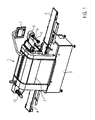
- Fig. 1 a first embodiment of the invention by way of example on a tray sealing machine, also called Traysealer described.
- Fig. 1 shows the tray sealer 1 with a feed belt 2, one or more workstations 3, eg an evacuation, sealing and cutting station, a discharge belt 4, a machine frame 5, a film tensioning device 6, an operating device 7, a film feed roller 8 for a film 9 and a Film winding device 10.
- cup-shaped packages are transported into or out of the work station 3 during operation.
- workstation 3 for example, the packages are evacuated, fumigated, sealed and cut.
- the film 9 is unwound from the film feed roll 8, passed through the film tensioning device 6, and stored in the work station 3, e.g. in the sealing tool, windows are cut out of the film web, which are sealed onto the cup-shaped packaging.
- the film web 9 is sealed onto the cup-shaped packages and then cut.
- the skeleton, that is the remaining film 9, leaves the work station 3 and is wound up by the Folienaufwickelvorraum 10.
- the Folienaufwickelvorraum 10 is formed so that it is in a winding position before the winding process and as long as this remains until the film 9 is to be removed.
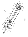
- Fig. 2 shows a partially sectioned view of a Folienierwickelvoroplasty invention 10. It comprises four paddles 11 and four connecting elements 12 which are arranged concentrically to a rotational axis A of the Folienierwickelvorraum 10.
- Each paddle 11 comprises a flat, plate-shaped body 11a made of plastic or metal, for example made of stainless steel, which is aligned in the longitudinal direction of the Folienierwickelvortechnik and is always in a radially aligned with the axis of rotation A level.
- the front end 13 of each paddle 11 is pivotally mounted by means of a lever pair 14 on a front pivot member 15.
- the respective front lever pair 14 is mounted on the front pivot member 15, via an outer pivot axis S3 on the respective paddle 11.
- the rear end 16 of each paddle 11 by means of another pair of levers 14 on a rear pivot member 17 is pivotable or rotatably mounted, with an inner pivot axis S2 between pivot member 17 and lever pair 14 and with an outer pivot axis S4 between lever pair 14 and paddle 11.
- the front pivot member 15 is connected by means of four connecting elements 12 with the rear pivot member 17, wherein the rear pivot member 17 is mounted concentrically on a shaft 18.
- the part of the shaft 18, which is located outside of the pivot elements 15, 17, serves as a storage or recording in the machine frame 5 and is driven by a drive, not shown, preferably a servo motor, to wind the film 9.
- a synchronization device 20 is arranged on the shaft 18, which has a synchronizing ring 21 displaceable along the axis of rotation A.
- the synchronizing ring 21 is in its outer region 22 with a respective recess 23 of each paddle 11 in contact. If a paddle 11 is moved, the synchronization ring 21 synchronizes the movement of all paddles 11. Is a foil ball 26, as in Fig.
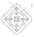
- Fig. 3 are shown in an end view, the paddle 11 in the winding position with the film bale 26.
- the paddles 11 and the pairs of levers 14 are aligned radially to the axis of rotation and attached together with the connecting elements 12 on the front pivot member 15.
- Fig. 4 shows a longitudinal section of the Folienierwickelvorraum 10 in the winding position with the wound-up film bale 26.
- the paddle 11 have on their side facing away from the rotation axis A outside 30 has a concave profile. If an operator attacks the film bale 26 in order to pull it down with respect to the drawing plane to the right from the film take-up device 10, the tensile force Z of the operator is transmitted via the friction between the innermost film layer and outer sides 30 of the four paddles 11 into a frictional force R and thus ensures a movement of the paddle 11 in the same direction.
- the front pair of levers 14 on the front pivot member 15 is inclined in the winding position by an angle ß between 90 ° and 85 ° relative to the axis of rotation A.
- the rear pair of levers 14 on the rear pivot member 17 is also inclined in the winding position by an angle ß between 90 ° and 85 ° on its side facing away from the paddle 11 side with respect to the axis of rotation A.
- the paddle 11 each move with its front end 13 by means of the lever pairs 14 about the first pivot axis S1 on the front pivot member 15 and with its rear end 16 by means of the lever pairs 14 about the second pivot axis S2 on the rear pivot member 17 such that during Moving the paddle 11 to the right to move the front ends 13 in the direction of the axis of rotation A faster than the rear ends 16.
- each paddle 11 performs a movement with a radial and axial movement component with respect to the axis of rotation A. This causes an inclination of the paddle 11 with a smaller outer dimension at the front pivot member 15 than at the rear pivot member 17.
- the spring 24 is biased further in the movement of the synchronization ring 21 against the holder 25. This leads to a small but still constantly existing frictional force R, which the operator has to apply when pulling down the foil bale 26.
- the paddles 11 are automatically moved from the removal position back into the winding-up position, without the influence of the operator, by moving the synchronization ring 21 towards the rear pivoting element 17 by means of the spring 24.
- the sides of the paddles 11 facing away from the axis of rotation A are aligned approximately parallel or concentric to the axis of rotation A.
- the pairs of levers 14 each of a paddle 11 form in the winding position together with the virtual lines that connect the inner and outer pivot axes S1 to S4 of the two pairs of levers 14, a trapezoid.
- Fig. 6 shows a further embodiment in which the pairs of levers 14 have a rectified orientation of the angle ß and thus the lever pairs 14 each of a paddle 11 form a parallelogram.
- the paddle 11 during movement from the winding position to the removal position are always aligned parallel or concentric with the axis of rotation A, in contrast to the cone formation in the former embodiment of Fig. 2 to 5 ,
- the outer sides 30 of the paddles 11 have a convex shape in order to automatically center the film 9 during winding, or are only just executed.
- a single lever instead of a pair of levers 14, a single lever may be provided.
Landscapes
- Auxiliary Devices For And Details Of Packaging Control (AREA)
Abstract
Description
- Die Erfindung bezieht sich auf eine Folienaufwickelvorrichtung für eine Verpackungsmaschine mit den Merkmalen des Anspruchs 1 sowie auf ein Verfahren mit den Merkmalen des Anspruchs 10.
- Aus der
EP 2 145 850 A1 ist eine Folienaufwickelvorrichtung für eine Schalenverschließmaschine bekannt, bei der mehrere S-förmige Paddel zwischen einer ersten eingeklappten und einer zweiten ausgeklappten Position bewegbar sind. Die Bewegung der Paddel zwischen diesen zwei Positionen wird mittels einer Relativbewegung zwischen einer Scheibe, die über Stifte mit den Paddeln in Kontakt tritt, und einem Rohr, in dem die Bleche gelagert sind, erzeugt. Nach dem Abziehen eines Folienballens müssen die Paddel wieder zurück in die ausgeklappte Position zum Aufwickeln einer neuen Folie gebracht werden. Hierzu ist eine manuell oder durch den Antrieb der Folienaufwickelvorrichtung erzeugte Relativbewegung in der Gegenrichtung notwendig. Wird dies vom Bedienpersonal nicht durchgeführt und die Folie aufgewickelt, führt dies zum Problem, dass dieser neu aufgewickelte Folienballen nicht mehr herunter gezogen werden kann. - Aufgabe der vorliegenden Erfindung ist es, eine Folienaufwickelvorrichtung für eine Verpackungsmaschine und ein Verfahren zum Betrieb einer solchen Folienaufwickelvorrichtung zur Verfügung zu stellen, die eine selbsttätige Rückstellung von einer Entnahmestellung in eine Aufwickelstellung ermöglicht.
- Diese Aufgabe wird gelöst durch eine Folienaufwickelvorrichtung für eine Verpackungsmaschine mit den Merkmalen des Anspruchs 1 bzw. durch ein Verfahren zum Betrieb einer solchen Folienaufwickelvorrichtung mit den Merkmalen des Anspruchs 10. Vorteilhafte Weiterbildungen der Erfindung sind in den Unteransprüchen angegeben.
- Die erfindungsgemäße Folienaufwickelvorrichtung für eine Verpackungsmaschine umfasst wenigstens drei Paddel, die dazu konfiguriert sind, jeweils an ihrer Außenseite eine Folie aufzuwickeln, und die zwischen einer Aufwickelstellung und einer Entnahmestellung bewegbar sind. Die Folienaufwickelvorrichtung zeichnet sich dadurch aus, dass jedes Paddel während seiner Bewegung zwischen der Aufwickelstellung und der Entnahmestellung eine axiale und eine radiale Bewegungskomponente gegenüber einer Drehachse der Folienaufwickelvorrichtung aufweist. Somit lassen sich die Paddel beim Herunterziehen eines Folienballens durch den Bediener von einer Aufwickelstellung in eine Entnahmestellung bewegen und nach dem Entfernen des Folienballens können die Paddel selbsttätig zurück in die Aufwickelstellung durch die Folienaufwickelvorrichtung selbst gebracht werden, ohne dass eine Aktion durch den Bediener vorgenommen werden muss. Es ist somit sichergestellt, dass vor jedem neuen Aufwickeln sich die Folienaufwickelvorrichtung in ihrer Aufwickelstellung befindet.
- Vorzugsweise weist die Folienaufwickelvorrichtung eine Synchronisierungsvorrichtung auf, so dass sich alle Paddel gemeinsam bewegen.
- Dabei weist die Synchronisierungsvorrichtung bevorzugt einen Synchronisationsring auf, der mit jeweils einer Aussparung eines jeden Paddels in Kontakt steht. Dies stellt eine einfache Konstruktion dar, um mit nur einem Aktor eine Vielzahl von Paddeln zu synchronisieren.
- Der Synchronisationsring ist in einer besonders vorteilhaften Ausführung mittels einer Feder vorspannbar, um ein automatisches bzw. selbsttätiges Rückstellen der Paddel in die Aufwickelstellung erzeugen zu können.
- Vorzugsweise weist die Folienaufwickelvorrichtung eine vordere Schwenkvorrichtung und eine hintere Schwenkvorrichtung auf. Dabei ist jedes Paddel mit seinem vorderen Ende an der vorderen Schwenkvorrichtung und mit seinem hinteren Ende an der hinteren Schwenkvorrichtung mittels jeweils eines Hebelpaars schwenkbar gelagert.
- Das Hebelpaar ist bevorzugt in einer radial zur Drehachse ausgerichteten Ebene bewegbar.
- Vorzugweise bildet jeweils ein Paddel mit seinen zugeordneten Hebelpaaren und den Schwenkvorrichtungen sowie mit einer virtuellen Verbindung zwischen einer ersten Schwenkachse am vorderen Schwenkelement und einer zweiten Schwenkachse am hinteren Schwenkelement ein Trapez oder ein Parallelogramm.
- Das vordere Hebelpaar weist bevorzugt in der Aufwickelstellung einen Winkel zwischen 90° und 85° gegenüber der Drehachse auf. Ein Winkel mit 90° oder kleiner ermöglicht eine Totpunktstellung beim Aufwickeln der Folie.
- Ein erfindungsgemäßes Verfahren zum Betrieb einer Folienaufwickelvorrichtung für eine Verpackungsmaschine, wobei die Folienaufwickelvorrichtung wenigstens drei bewegbare Paddel und eine Drehachse umfasst, zeichnet sich dadurch aus, dass sich die Paddel bei einer Bewegung zwischen der Aufwickelstellung und der Entnahmestellung in einer axialen und radialen Richtung gegenüber der Drehachse bewegen.
- Vorzugsweise werden nach dem Entfernen eines Folienballens die Paddel automatisch bzw. selbsttätig in die Aufwickelstellung zurückbewegt, ohne dass der Bediener vor dem Aufwickeln der nächsten Folie daran denken muss.
- Bevorzugt bewegen sich die Paddel synchron. Dabei erzeugt vorzugsweise eine entlang der Drehachse bewegbare Synchronisierungsvorrichtung die Bewegung der Paddel in die Aufwickelstellung.
- In einer besonders vorteilhaften Ausführung wird jedes Paddel an einer vorderen Schwenkvorrichtung radial näher an die Drehachse der Folienaufwickelvorrichtung bewegt als zeitgleich an einer hinteren Schwenkvorrichtung. So kann eine Konusform erreicht werden mit dem reduzierten Durchmesser an der Entnahmeseite, die das Herunterziehen erleichtert.
- Im Folgenden wird ein vorteilhaftes Ausführungsbeispiel der Erfindung anhand einer Zeichnung näher erläutert. Im Einzelnen zeigen:
- Fig. 1
- eine schematische perspektivische Ansicht einer Schalenverschließmaschine,
- Fig. 2
- eine perspektivische teilgeschnittene Ansicht einer ersten Ausführung einer erfindungsgemäßen Folienaufwickelvorrichtung,
- Fig. 3
- eine Stirnansicht der Folienaufwickelvorrichtung,
- Fig. 4
- eine schematische Längsschnittsansicht der Folienaufwickelvorrichtung in einer Aufwickelstellung,
- Fig. 5
- eine schematische Längsschnittsansicht der Folienaufwickelvorrichtung in einer Entnahmestellung und
- Fig. 6
- eine weitere Ausführung der erfindungsgemäßen Folienaufwickelvorrichtung.
- Gleiche Komponenten sind in den Figuren durchgängig mit gleichen Bezugszeichen versehen.
- Im Folgenden wird mit Bezug auf
Fig. 1 eine erste Ausführungsform der Erfindung beispielhaft an einer Schalenverschließmaschine, auch Traysealer genannt, beschrieben. -
Fig. 1 zeigt den Traysealer 1 mit einem Zuführband 2, einer oder mehreren Arbeitsstationen 3, z.B. einer Evakuier-, Siegel- und Schneidstation, einem Abführband 4, einem Maschinengestell 5, einer Folienspannvorrichtung 6, einer Bedienvorrichtung 7, einer Folienzuführrolle 8 für eine Folie 9 und einer Folienaufwickelvorrichtung 10. - Auf dem Zuführband 2 bzw. dem Abführband 4 werden im Betrieb beispielsweise schalenförmige Verpackungen in die Arbeitsstation 3 hinein bzw. aus ihr heraus transportiert. In der Arbeitsstation 3 werden die Verpackungen zum Beispiel evakuiert, begast, versiegelt und geschnitten. Die Folie 9 wird von der Folienzuführrolle 8 abgewickelt, durch die Folienspannvorrichtung 6 geführt, und in der Arbeitsstation 3, z.B. im Siegelwerkzeug, werden aus der Folienbahn Fenster herausgeschnitten, die auf die schalenförmigen Verpackungen aufgesiegelt werden. Alternativ wird die Folienbahn 9 auf die schalenförmigen Verpackungen aufgesiegelt und danach geschnitten. Das Restgitter, also die verbleibende Folie 9, verlässt die Arbeitsstation 3 und wird von der Folienaufwickelvorrichtung 10 aufgewickelt. Die Folienaufwickelvorrichtung 10 ist so ausgebildet, dass sie sich vor dem Aufwickelvorgang in einer Aufwickelstellung befindet und solange in dieser verbleibt, bis die Folie 9 abgenommen werden soll.
-
Fig. 2 zeigt eine teilgeschnittene Ansicht einer erfindungsgemäßen Folienaufwickelvorrichtung 10. Sie umfasst vier Paddel 11 und vier Verbindungselemente 12, die konzentrisch zu einer Drehachse A der Folienaufwickelvorrichtung 10 angeordnet sind. Jedes Paddel 11 umfasst einen ebenen, plattenförmigen Körper 11a aus Kunststoff oder Metall, z.B. aus Edelstahl, der in Längsrichtung der Folienaufwickelvorrichtung ausgerichtet ist und sich stets in einer radial zur Drehachse A ausgerichteten Ebene befindet. Das vordere Ende 13 eines jeden Paddels 11 ist mittels eines Hebelpaars 14 an einem vorderen Schwenkelement 15 schwenkbar bzw. drehbar angebracht. Über eine erste, innere Schwenkachse S1 ist das jeweilige vordere Hebelpaar 14 am vorderen Schwenkelement 15 gelagert, über eine äußere Schwenkachse S3 am jeweiligen Paddel 11. Analog ist das hintere Ende 16 eines jeden Paddels 11 mittels eines weiteren Hebelpaars 14 an einem hinteren Schwenkelement 17 schwenkbar bzw. drehbar angebracht, und zwar mit einer inneren Schwenkachse S2 zwischen Schwenkelement 17 und Hebelpaar 14 sowie mit einer äußeren Schwenkachse S4 zwischen Hebelpaar 14 und Paddel 11. Das vordere Schwenkelement 15 ist mittels der vier Verbindungselemente 12 mit dem hinteren Schwenkelement 17 verbunden, wobei das hintere Schwenkelement 17 konzentrisch auf einer Welle 18 angebracht ist. Der Teil der Welle 18, der sich außerhalb der Schwenkelemente 15, 17 befindet, dient als Lagerung bzw. Aufnahme im Maschinengestell 5 und wird über einen nicht gezeigten Antrieb, vorzugsweise einen Servomotor, angetrieben, um die Folie 9 aufzuwickeln. - Zwischen den Schwenkelementen 15, 17 ist auf der Welle 18 eine Synchronisierungssvorrichtung 20 angeordnet, die einen entlang der Drehachse A verschiebbaren Synchronisationsring 21 aufweist. Der Synchronisierungsring 21 steht in seinem äußeren Bereich 22 mit jeweils einer Aussparung 23 eines jeden Paddels 11 in Kontakt. Wird ein Paddel 11 bewegt, so synchronisiert der Synchronisationsring 21 die Bewegung aller Paddel 11. Ist ein Folienballen 26, wie in
Fig. 3 gezeigt, von der Folienaufwickelvorrichtung 10 heruntergenommen worden, so sorgt der über eine Feder 24 an einem Halter 25 vorgespannte Synchronisationsring 21 für eine synchronisierte Bewegung aller Paddel 11 zurück in die Aufwickelstellung, bei der sich alle Paddel 11 in ihrer radial zur Drehachse A entferntesten Stellung befinden und gemeinsam einen virtuellen maximalen Durchmesser bilden. Als Anschlag für diese Stellung kann der Halter 25 gegenüber den Paddeln 11 dienen, oder der Synchronisationsring 21 kann an einem Absatz 18a an der Welle 18 anschlagen. - In
Fig. 3 sind in einer Stirnansicht die Paddel 11 in der Aufwickelstellung mit dem Folienballen 26 gezeigt. Die Paddel 11 und die Hebelpaare 14 sind radial zur Drehachse ausgerichtet und zusammen mit den Verbindungselementen 12 am vorderen Schwenkelement 15 angebracht. -
Fig. 4 zeigt einen Längsschnitt der Folienaufwickelvorrichtung 10 in der Aufwickelstellung mit dem aufgewickelten Folienballen 26. Die Paddel 11 weisen an ihrer von der Drehachse A abgewandten Außenseite 30 einen konkaven Verlauf auf. Greift ein Bediener an dem Folienballen 26 an, um ihn bzgl. der Zeichnungsebene nach rechts von der Folienaufwickelvorrichtung 10 herunterzuziehen, so wird die Zugkraft Z des Bedieners über die Reibung zwischen der innersten Folienlage und Außenseiten 30 der vier Paddel 11 in eine Reibkraft R übertragen und sorgt somit für eine Bewegung der Paddel 11 in der gleichen Richtung. Das vordere Hebelpaar 14 an dem vorderen Schwenkelement 15 ist in der Aufwickelstellung um einen Winkel ß zwischen 90° und 85° gegenüber der Drehachse A geneigt. Das hintere Hebelpaar 14 am hinteren Schwenkelement 17 ist in der Aufwickelstellung ebenfalls um einen Winkel ß zwischen 90° und 85° an seiner vom Paddel 11 abgewandten Seite gegenüber der Drehachse A geneigt. - Wie in
Fig. 5 gezeigt, bewegen sich die Paddel 11 jeweils mit ihrem vorderen Ende 13 mittels der Hebelpaare 14 um die erste Schwenkachse S1 am vorderen Schwenkelement 15 und mit ihrem hinteren Ende 16 mittels der Hebelpaare 14 um die zweite Schwenkachse S2 am hinteren Schwenkelement 17 derart, dass sich während der Bewegung der Paddel 11 nach rechts die vorderen Enden 13 schneller in Richtung der Drehachse A bewegen als die hinteren Enden 16. Dabei führt jedes Paddel 11 eine Bewegung mit einer radialen und axialen Bewegungskomponente bezogen auf die Drehachse A aus. Dies bewirkt eine Schrägstellung der Paddel 11 mit einer geringeren Außenabmessung am vorderen Schwenkelement 15 als am hinteren Schwenkelement 17. Hätte die Aufwickelvorrichtung 10 eine beliebig große Anzahl von Paddeln 11, so würde sich in dieser Stellung insgesamt eine konische Außenform der Aufwickelvorrichtung 10 ergeben. Daraus resultiert eine geringere Zugkraft Z, die vom Bediener zum Herunternehmen aufgebracht werden muss, da sich die Kontaktfläche zwischen der innersten Folienlage des Folienballens 26 und den Außenseiten 30 der Paddel 11 verringert. - Die Feder 24 wird bei der Bewegung des Synchronisationsrings 21 gegen den Halter 25 weiter vorgespannt. Dies führt zu einer geringen aber trotzdem noch ständig vorhandenen Reibkraft R, die der Bediener beim Herunterziehen des Folienballens 26 aufbringen muss. Sobald der Folienballen 26 entfernt ist, werden die Paddel 11 selbsttätig, nämlich ohne einen Einfluss durch den Bediener, von der Entnahmestellung zurück in die Aufwickelstellung bewegt, indem der Synchronisationsring 21 durch die Feder 24 zum hinteren Schwenkelement 17 hin bewegt wird. In der Aufwickelstellung sind die von der Drehachse A abgewandten Seiten der Paddel 11 annähernd parallel bzw. konzentrisch zur Drehachse A ausgerichtet. Die Hebelpaare 14 jeweils eines Paddels 11 bilden in der Aufwickelstellung zusammen mit den virtuellen Linien, die die inneren und die äußeren Schwenkachsen S1 bis S4 der beiden Hebelpaare 14 miteinander verbinden, ein Trapez.
-
Fig. 6 zeigt eine weitere Ausführung, bei der die Hebelpaare 14 eine gleichgerichtete Ausrichtung des Winkels ß aufweisen und somit die Hebelpaare 14 jeweils eines Paddels 11 ein Parallelogramm bilden. Bei dieser Ausführung sind die Paddel 11 während der Bewegung von der Aufwickelstellung in die Entnahmestellung immer parallel bzw. konzentrisch zur Drehachse A ausgerichtet, im Gegensatz zur Konusbildung bei der ersteren Ausführung vonFig. 2 bis 5 . - Denkbar ist auch, dass die Außenseiten 30 der Paddel 11 eine konvexe Form aufweisen, um die Folie 9 beim Aufwickeln selbsttätig zu zentrieren, oder lediglich gerade ausgeführt sind. Erfindungsgemäß kann anstatt eines Hebelpaars 14 ein einzelner Hebel vorgesehen sein.
Claims (14)
- Folienaufwickelvorrichtung (10) für eine Verpackungsmaschine (1), wobei die Folienaufwickelvorrichtung (10) wenigstens drei Paddel (11) umfasst, die dazu konfiguriert sind, an ihrer Außenseite (30) eine Folie (9) aufzuwickeln, und die zwischen einer Aufwickelstellung und einer Entnahmestellung bewegbar sind, dadurch gekennzeichnet, dass jedes Paddel (11) während seiner Bewegung zwischen der Aufwickelstellung und der Entnahmestellung eine axiale und eine radiale Bewegungskomponente gegenüber einer Drehachse (A) der Folienaufwickelvorrichtung (10) aufweist.
- Folienaufwickelvorrichtung nach Anspruch 1, dadurch gekennzeichnet, dass die Folienaufwickelvorrichtung (10) eine Synchronisierungsvorrichtung (20) aufweist.
- Folienaufwickelvorrichtung nach Anspruch 2, dadurch gekennzeichnet, dass die Synchronisierungsvorrichtung (20) einen Synchronisationsring (21) aufweist, der mit jeweils einer Aussparung (23) eines jeden Paddels (11) in Kontakt steht.
- Folienaufwickelvorrichtung nach Anspruch 3, dadurch gekennzeichnet, dass der Synchronisationsring (21) mittels einer Feder (24) vorgespannt ist.
- Folienaufwickelvorrichtung nach einem der vorangehenden Ansprüche, dadurch gekennzeichnet, dass die Folienaufwickelvorrichtung (10) eine vordere Schwenkvorrichtung (15) und eine hintere Schwenkvorrichtung (17) aufweist.
- Folienaufwickelvorrichtung nach Anspruch 5, dadurch gekennzeichnet, dass jedes Paddel (11) mit seinem vorderen Ende (13) an der vorderen Schwenkvorrichtung (15) und mit seinem hinteren Ende (16) an der hinteren Schwenkvorrichtung (17) mittels jeweils einesHebelpaars (14) schwenkbar gelagert ist.
- Folienaufwickelvorrichtung nach Anspruch 6, dadurch gekennzeichnet, dass jedes Hebelpaar (14) in einer radial zur Drehachse (A) ausgerichteten Ebene bewegbar ist.
- Folienaufwickelvorrichtung nach Anspruch 7, dadurch gekennzeichnet, dass jeweils ein Paddel (11) mit den zugeordneten Hebelpaaren (14) und den Schwenkvorrichtungen (15, 17) sowie mit einer virtuellen Verbindung zwischen einer ersten Schwenkachse (S1) am vorderen Schwenkelement (15) und einer zweiten Schwenkachse (S2) am hinteren Schwenkelement (17) ein Trapez oder ein Parallelogramm bildet.
- Folienaufwickelvorrichtung nach Anspruch 8, dadurch gekennzeichnet, dass das vordere Hebelpaar (14) in der Aufwickelstellung einen Winkel (ß) zwischen 90° und 85° gegenüber der Drehachse (A) aufweist.
- Verfahren zum Betrieb einer Folienaufwickelvorrichtung (10) für eine Verpackungsmaschine (1), wobei die Folienaufwickelvorrichtung (10) wenigstens drei bewegbare Paddel (11) und eine Drehachse (A) umfasst, dadurch gekennzeichnet, dass sich die Paddel (11) bei einer Bewegung zwischen der Aufwickelstellung und der Entnahmestellung in einer axialen und radialen Richtung gegenüber der Drehachse (A) bewegen.
- Verfahren nach Anspruch 10, dadurch gekennzeichnet, dass nach dem Entfernen eines Folienballens (26) die Paddel (11) automatisch in die Aufwickelstellung zurückbewegt werden.
- Verfahren nach einem der Ansprüche 10 bis 11, dadurch gekennzeichnet, dass sich die Paddel (11) synchron bewegen.
- Verfahren nach Anspruch 12, dadurch gekennzeichnet, dass eine entlang der Drehachse (A) bewegbare Synchronisierungsvorrichtung (21) die Bewegung der Paddel (11) in die Aufwickelstellung erzeugt.
- Verfahren nach einem der Ansprüche 10 bis 13, dadurch gekennzeichnet, dass jedes Paddel (14) an einer vorderen Schwenkvorrichtung (15) radial näher an die Drehachse (A) der Folienaufwickelvorrichtung (10) bewegt wird als zeitgleich an einer hinteren Schwenkvorrichtung (17).
Priority Applications (1)
| Application Number | Priority Date | Filing Date | Title |
|---|---|---|---|
| EP14185387.9A EP2998258B1 (de) | 2014-09-18 | 2014-09-18 | Folienaufwickelvorrichtung für eine Verpackungsmaschine |
Applications Claiming Priority (1)
| Application Number | Priority Date | Filing Date | Title |
|---|---|---|---|
| EP14185387.9A EP2998258B1 (de) | 2014-09-18 | 2014-09-18 | Folienaufwickelvorrichtung für eine Verpackungsmaschine |
Publications (2)
| Publication Number | Publication Date |
|---|---|
| EP2998258A1 true EP2998258A1 (de) | 2016-03-23 |
| EP2998258B1 EP2998258B1 (de) | 2019-09-11 |
Family
ID=51570331
Family Applications (1)
| Application Number | Title | Priority Date | Filing Date |
|---|---|---|---|
| EP14185387.9A Not-in-force EP2998258B1 (de) | 2014-09-18 | 2014-09-18 | Folienaufwickelvorrichtung für eine Verpackungsmaschine |
Country Status (1)
| Country | Link |
|---|---|
| EP (1) | EP2998258B1 (de) |
Cited By (1)
| Publication number | Priority date | Publication date | Assignee | Title |
|---|---|---|---|---|
| EP3868693A1 (de) | 2020-02-21 | 2021-08-25 | MULTIVAC Sepp Haggenmüller SE & Co. KG | Restfolienwickler für eine verpackungsmaschine |
Families Citing this family (1)
| Publication number | Priority date | Publication date | Assignee | Title |
|---|---|---|---|---|
| CN111824815B (zh) * | 2020-06-10 | 2021-11-05 | 桐乡市中瑞环保科技有限公司 | 一种裁切后的熔喷布的收卷装置 |
Citations (6)
| Publication number | Priority date | Publication date | Assignee | Title |
|---|---|---|---|---|
| JPS4875079U (de) * | 1971-12-18 | 1973-09-18 | ||
| JPS5395969U (de) * | 1976-12-04 | 1978-08-04 | ||
| JPH1143242A (ja) * | 1997-07-25 | 1999-02-16 | Hitachi Chem Co Ltd | フィルム巻取り装置 |
| JP2002012347A (ja) * | 2000-06-30 | 2002-01-15 | Hagihara Industries Inc | かせ枠巻取巻出装置 |
| JP2003321151A (ja) * | 2002-05-02 | 2003-11-11 | Millennium Service Corporation:Kk | 巻物支持軸、巻取装置および巻出装置 |
| EP2145850A1 (de) | 2008-07-16 | 2010-01-20 | MULTIVAC Sepp Haggenmüller GmbH & Co KG | Verpackungsmaschine mit einer Folienaufwickelvorrichtung |
-
2014
- 2014-09-18 EP EP14185387.9A patent/EP2998258B1/de not_active Not-in-force
Patent Citations (6)
| Publication number | Priority date | Publication date | Assignee | Title |
|---|---|---|---|---|
| JPS4875079U (de) * | 1971-12-18 | 1973-09-18 | ||
| JPS5395969U (de) * | 1976-12-04 | 1978-08-04 | ||
| JPH1143242A (ja) * | 1997-07-25 | 1999-02-16 | Hitachi Chem Co Ltd | フィルム巻取り装置 |
| JP2002012347A (ja) * | 2000-06-30 | 2002-01-15 | Hagihara Industries Inc | かせ枠巻取巻出装置 |
| JP2003321151A (ja) * | 2002-05-02 | 2003-11-11 | Millennium Service Corporation:Kk | 巻物支持軸、巻取装置および巻出装置 |
| EP2145850A1 (de) | 2008-07-16 | 2010-01-20 | MULTIVAC Sepp Haggenmüller GmbH & Co KG | Verpackungsmaschine mit einer Folienaufwickelvorrichtung |
Cited By (2)
| Publication number | Priority date | Publication date | Assignee | Title |
|---|---|---|---|---|
| EP3868693A1 (de) | 2020-02-21 | 2021-08-25 | MULTIVAC Sepp Haggenmüller SE & Co. KG | Restfolienwickler für eine verpackungsmaschine |
| US11629025B2 (en) | 2020-02-21 | 2023-04-18 | Multivac Sepp Haggenmueller Se & Co. Kg | Residual film winder for a packaging machine |
Also Published As
| Publication number | Publication date |
|---|---|
| EP2998258B1 (de) | 2019-09-11 |
Similar Documents
| Publication | Publication Date | Title |
|---|---|---|
| DE3873869T2 (de) | Verfahren und vorrichtung zum aufbringen eines wulstfuellers auf einen wulstkernring. | |
| DE10035894B4 (de) | Wickeleinrichtung für Bandmaterial | |
| EP1801047B1 (de) | Stapelgreifer | |
| DE2558998B2 (de) | Vorrichtung zum Schneiden einer mit einem Hohlkern versehenen Wickelrolle | |
| EP2803609B1 (de) | Maschine zum Aufwickeln von bahnförmigen Materialien | |
| EP2942303B1 (de) | Aufwickelhaspel für Etikettenspender | |
| EP2079654A1 (de) | Schwenkbare anlegewalze im wendewickler | |
| EP2998258B1 (de) | Folienaufwickelvorrichtung für eine Verpackungsmaschine | |
| EP3060484B1 (de) | Vorrichtung und verfahren zum wechseln von bonrollen einer etikettiermaschine | |
| DE102014226859B4 (de) | Rollenentnahmeeinrichtung, Wickeleinrichtung und Verfahren zum Abtransport von mehreren fertig gewickelten Rollen | |
| AT520462A1 (de) | Verfahren zum Querschneiden einer entlang einer Bewegungsrichtung bewegten Materialbahn sowie Vorrichtung hierzu | |
| DE2241525A1 (de) | Vorrichtung zum anbringen von fensterflecken an umschlagrohlingen | |
| DE2259485A1 (de) | Vorrichtung zum verbinden von materialbahnen | |
| EP3722071B1 (de) | Vorrichtung zum applizieren einer perforierten schutzfolie auf eine oberfläche eines bauteils | |
| EP3187439A1 (de) | Zangengeber | |
| DE2243504C2 (de) | Vorrichtung zum fortlaufenden Aufwickeln einer Folienbahn auf Wickelhülsen | |
| DE10224839B4 (de) | Spanndorn | |
| EP1712471B1 (de) | Vorrichtung und Verfahren zur Verpackung von Artikeln | |
| EP3695914A1 (de) | Abhaspelvorrichtung und -verfahren | |
| EP2808281A2 (de) | Spleißeinrichtung zum Spleißen von Cordmaterial | |
| WO2020127399A1 (de) | Wickelvorrichtung | |
| DE2910633A1 (de) | Vorrichtung zum biegen, sicken und ablaengen der anschlussdraehte von elektrischen bauelementen | |
| DE102012218683A1 (de) | Vorrichtung zur Herstellung eines Polsterungsprodukts aus Papier | |
| WO2017050478A1 (de) | Verfahren zur handhabung von vorratsrollen mit flaechigem bandmaterial, vorratsrolle und vorrichtung zum bereitstellen flaechigen bandmaterials | |
| DE10058437B4 (de) | Vorrichtungen zum Verbinden zweier Materialbahnen |
Legal Events
| Date | Code | Title | Description |
|---|---|---|---|
| PUAI | Public reference made under article 153(3) epc to a published international application that has entered the european phase |
Free format text: ORIGINAL CODE: 0009012 |
|
| AK | Designated contracting states |
Kind code of ref document: A1 Designated state(s): AL AT BE BG CH CY CZ DE DK EE ES FI FR GB GR HR HU IE IS IT LI LT LU LV MC MK MT NL NO PL PT RO RS SE SI SK SM TR |
|
| AX | Request for extension of the european patent |
Extension state: BA ME |
|
| 17P | Request for examination filed |
Effective date: 20160912 |
|
| RBV | Designated contracting states (corrected) |
Designated state(s): AL AT BE BG CH CY CZ DE DK EE ES FI FR GB GR HR HU IE IS IT LI LT LU LV MC MK MT NL NO PL PT RO RS SE SI SK SM TR |
|
| STAA | Information on the status of an ep patent application or granted ep patent |
Free format text: STATUS: EXAMINATION IS IN PROGRESS |
|
| 17Q | First examination report despatched |
Effective date: 20180720 |
|
| GRAP | Despatch of communication of intention to grant a patent |
Free format text: ORIGINAL CODE: EPIDOSNIGR1 |
|
| STAA | Information on the status of an ep patent application or granted ep patent |
Free format text: STATUS: GRANT OF PATENT IS INTENDED |
|
| INTG | Intention to grant announced |
Effective date: 20190401 |
|
| GRAS | Grant fee paid |
Free format text: ORIGINAL CODE: EPIDOSNIGR3 |
|
| GRAA | (expected) grant |
Free format text: ORIGINAL CODE: 0009210 |
|
| STAA | Information on the status of an ep patent application or granted ep patent |
Free format text: STATUS: THE PATENT HAS BEEN GRANTED |
|
| AK | Designated contracting states |
Kind code of ref document: B1 Designated state(s): AL AT BE BG CH CY CZ DE DK EE ES FI FR GB GR HR HU IE IS IT LI LT LU LV MC MK MT NL NO PL PT RO RS SE SI SK SM TR |
|
| REG | Reference to a national code |
Ref country code: GB Ref legal event code: FG4D Free format text: NOT ENGLISH |
|
| REG | Reference to a national code |
Ref country code: CH Ref legal event code: EP |
|
| REG | Reference to a national code |
Ref country code: AT Ref legal event code: REF Ref document number: 1178214 Country of ref document: AT Kind code of ref document: T Effective date: 20190915 |
|
| REG | Reference to a national code |
Ref country code: DE Ref legal event code: R096 Ref document number: 502014012614 Country of ref document: DE Ref country code: IE Ref legal event code: FG4D Free format text: LANGUAGE OF EP DOCUMENT: GERMAN |
|
| REG | Reference to a national code |
Ref country code: NL Ref legal event code: FP |
|
| REG | Reference to a national code |
Ref country code: LT Ref legal event code: MG4D |
|
| PG25 | Lapsed in a contracting state [announced via postgrant information from national office to epo] |
Ref country code: NO Free format text: LAPSE BECAUSE OF FAILURE TO SUBMIT A TRANSLATION OF THE DESCRIPTION OR TO PAY THE FEE WITHIN THE PRESCRIBED TIME-LIMIT Effective date: 20191211 Ref country code: HR Free format text: LAPSE BECAUSE OF FAILURE TO SUBMIT A TRANSLATION OF THE DESCRIPTION OR TO PAY THE FEE WITHIN THE PRESCRIBED TIME-LIMIT Effective date: 20190911 Ref country code: SE Free format text: LAPSE BECAUSE OF FAILURE TO SUBMIT A TRANSLATION OF THE DESCRIPTION OR TO PAY THE FEE WITHIN THE PRESCRIBED TIME-LIMIT Effective date: 20190911 Ref country code: FI Free format text: LAPSE BECAUSE OF FAILURE TO SUBMIT A TRANSLATION OF THE DESCRIPTION OR TO PAY THE FEE WITHIN THE PRESCRIBED TIME-LIMIT Effective date: 20190911 Ref country code: LT Free format text: LAPSE BECAUSE OF FAILURE TO SUBMIT A TRANSLATION OF THE DESCRIPTION OR TO PAY THE FEE WITHIN THE PRESCRIBED TIME-LIMIT Effective date: 20190911 Ref country code: BG Free format text: LAPSE BECAUSE OF FAILURE TO SUBMIT A TRANSLATION OF THE DESCRIPTION OR TO PAY THE FEE WITHIN THE PRESCRIBED TIME-LIMIT Effective date: 20191211 |
|
| PG25 | Lapsed in a contracting state [announced via postgrant information from national office to epo] |
Ref country code: ES Free format text: LAPSE BECAUSE OF FAILURE TO SUBMIT A TRANSLATION OF THE DESCRIPTION OR TO PAY THE FEE WITHIN THE PRESCRIBED TIME-LIMIT Effective date: 20190911 Ref country code: LV Free format text: LAPSE BECAUSE OF FAILURE TO SUBMIT A TRANSLATION OF THE DESCRIPTION OR TO PAY THE FEE WITHIN THE PRESCRIBED TIME-LIMIT Effective date: 20190911 Ref country code: AL Free format text: LAPSE BECAUSE OF FAILURE TO SUBMIT A TRANSLATION OF THE DESCRIPTION OR TO PAY THE FEE WITHIN THE PRESCRIBED TIME-LIMIT Effective date: 20190911 Ref country code: RS Free format text: LAPSE BECAUSE OF FAILURE TO SUBMIT A TRANSLATION OF THE DESCRIPTION OR TO PAY THE FEE WITHIN THE PRESCRIBED TIME-LIMIT Effective date: 20190911 Ref country code: GR Free format text: LAPSE BECAUSE OF FAILURE TO SUBMIT A TRANSLATION OF THE DESCRIPTION OR TO PAY THE FEE WITHIN THE PRESCRIBED TIME-LIMIT Effective date: 20191212 |
|
| PG25 | Lapsed in a contracting state [announced via postgrant information from national office to epo] |
Ref country code: PT Free format text: LAPSE BECAUSE OF FAILURE TO SUBMIT A TRANSLATION OF THE DESCRIPTION OR TO PAY THE FEE WITHIN THE PRESCRIBED TIME-LIMIT Effective date: 20200113 Ref country code: RO Free format text: LAPSE BECAUSE OF FAILURE TO SUBMIT A TRANSLATION OF THE DESCRIPTION OR TO PAY THE FEE WITHIN THE PRESCRIBED TIME-LIMIT Effective date: 20190911 Ref country code: PL Free format text: LAPSE BECAUSE OF FAILURE TO SUBMIT A TRANSLATION OF THE DESCRIPTION OR TO PAY THE FEE WITHIN THE PRESCRIBED TIME-LIMIT Effective date: 20190911 Ref country code: EE Free format text: LAPSE BECAUSE OF FAILURE TO SUBMIT A TRANSLATION OF THE DESCRIPTION OR TO PAY THE FEE WITHIN THE PRESCRIBED TIME-LIMIT Effective date: 20190911 Ref country code: IT Free format text: LAPSE BECAUSE OF FAILURE TO SUBMIT A TRANSLATION OF THE DESCRIPTION OR TO PAY THE FEE WITHIN THE PRESCRIBED TIME-LIMIT Effective date: 20190911 |
|
| PG25 | Lapsed in a contracting state [announced via postgrant information from national office to epo] |
Ref country code: IS Free format text: LAPSE BECAUSE OF FAILURE TO SUBMIT A TRANSLATION OF THE DESCRIPTION OR TO PAY THE FEE WITHIN THE PRESCRIBED TIME-LIMIT Effective date: 20200224 Ref country code: SM Free format text: LAPSE BECAUSE OF FAILURE TO SUBMIT A TRANSLATION OF THE DESCRIPTION OR TO PAY THE FEE WITHIN THE PRESCRIBED TIME-LIMIT Effective date: 20190911 Ref country code: SK Free format text: LAPSE BECAUSE OF FAILURE TO SUBMIT A TRANSLATION OF THE DESCRIPTION OR TO PAY THE FEE WITHIN THE PRESCRIBED TIME-LIMIT Effective date: 20190911 Ref country code: CZ Free format text: LAPSE BECAUSE OF FAILURE TO SUBMIT A TRANSLATION OF THE DESCRIPTION OR TO PAY THE FEE WITHIN THE PRESCRIBED TIME-LIMIT Effective date: 20190911 |
|
| REG | Reference to a national code |
Ref country code: CH Ref legal event code: PL |
|
| REG | Reference to a national code |
Ref country code: DE Ref legal event code: R097 Ref document number: 502014012614 Country of ref document: DE |
|
| PLBE | No opposition filed within time limit |
Free format text: ORIGINAL CODE: 0009261 |
|
| STAA | Information on the status of an ep patent application or granted ep patent |
Free format text: STATUS: NO OPPOSITION FILED WITHIN TIME LIMIT |
|
| PG2D | Information on lapse in contracting state deleted |
Ref country code: IS |
|
| PG25 | Lapsed in a contracting state [announced via postgrant information from national office to epo] |
Ref country code: LI Free format text: LAPSE BECAUSE OF NON-PAYMENT OF DUE FEES Effective date: 20190930 Ref country code: DK Free format text: LAPSE BECAUSE OF FAILURE TO SUBMIT A TRANSLATION OF THE DESCRIPTION OR TO PAY THE FEE WITHIN THE PRESCRIBED TIME-LIMIT Effective date: 20190911 Ref country code: LU Free format text: LAPSE BECAUSE OF NON-PAYMENT OF DUE FEES Effective date: 20190918 Ref country code: IE Free format text: LAPSE BECAUSE OF NON-PAYMENT OF DUE FEES Effective date: 20190918 Ref country code: CH Free format text: LAPSE BECAUSE OF NON-PAYMENT OF DUE FEES Effective date: 20190930 Ref country code: IS Free format text: LAPSE BECAUSE OF FAILURE TO SUBMIT A TRANSLATION OF THE DESCRIPTION OR TO PAY THE FEE WITHIN THE PRESCRIBED TIME-LIMIT Effective date: 20200112 |
|
| REG | Reference to a national code |
Ref country code: BE Ref legal event code: MM Effective date: 20190930 |
|
| 26N | No opposition filed |
Effective date: 20200615 |
|
| PG25 | Lapsed in a contracting state [announced via postgrant information from national office to epo] |
Ref country code: BE Free format text: LAPSE BECAUSE OF NON-PAYMENT OF DUE FEES Effective date: 20190930 Ref country code: MC Free format text: LAPSE BECAUSE OF FAILURE TO SUBMIT A TRANSLATION OF THE DESCRIPTION OR TO PAY THE FEE WITHIN THE PRESCRIBED TIME-LIMIT Effective date: 20190911 Ref country code: SI Free format text: LAPSE BECAUSE OF FAILURE TO SUBMIT A TRANSLATION OF THE DESCRIPTION OR TO PAY THE FEE WITHIN THE PRESCRIBED TIME-LIMIT Effective date: 20190911 |
|
| REG | Reference to a national code |
Ref country code: AT Ref legal event code: MM01 Ref document number: 1178214 Country of ref document: AT Kind code of ref document: T Effective date: 20190918 |
|
| PG25 | Lapsed in a contracting state [announced via postgrant information from national office to epo] |
Ref country code: AT Free format text: LAPSE BECAUSE OF NON-PAYMENT OF DUE FEES Effective date: 20190918 |
|
| PG25 | Lapsed in a contracting state [announced via postgrant information from national office to epo] |
Ref country code: CY Free format text: LAPSE BECAUSE OF FAILURE TO SUBMIT A TRANSLATION OF THE DESCRIPTION OR TO PAY THE FEE WITHIN THE PRESCRIBED TIME-LIMIT Effective date: 20190911 |
|
| PG25 | Lapsed in a contracting state [announced via postgrant information from national office to epo] |
Ref country code: MT Free format text: LAPSE BECAUSE OF FAILURE TO SUBMIT A TRANSLATION OF THE DESCRIPTION OR TO PAY THE FEE WITHIN THE PRESCRIBED TIME-LIMIT Effective date: 20190911 Ref country code: HU Free format text: LAPSE BECAUSE OF FAILURE TO SUBMIT A TRANSLATION OF THE DESCRIPTION OR TO PAY THE FEE WITHIN THE PRESCRIBED TIME-LIMIT; INVALID AB INITIO Effective date: 20140918 |
|
| PG25 | Lapsed in a contracting state [announced via postgrant information from national office to epo] |
Ref country code: TR Free format text: LAPSE BECAUSE OF FAILURE TO SUBMIT A TRANSLATION OF THE DESCRIPTION OR TO PAY THE FEE WITHIN THE PRESCRIBED TIME-LIMIT Effective date: 20190911 |
|
| PG25 | Lapsed in a contracting state [announced via postgrant information from national office to epo] |
Ref country code: MK Free format text: LAPSE BECAUSE OF FAILURE TO SUBMIT A TRANSLATION OF THE DESCRIPTION OR TO PAY THE FEE WITHIN THE PRESCRIBED TIME-LIMIT Effective date: 20190911 |
|
| PGFP | Annual fee paid to national office [announced via postgrant information from national office to epo] |
Ref country code: NL Payment date: 20220922 Year of fee payment: 9 Ref country code: GB Payment date: 20220927 Year of fee payment: 9 Ref country code: DE Payment date: 20220920 Year of fee payment: 9 |
|
| PGFP | Annual fee paid to national office [announced via postgrant information from national office to epo] |
Ref country code: FR Payment date: 20220920 Year of fee payment: 9 |
|
| P01 | Opt-out of the competence of the unified patent court (upc) registered |
Effective date: 20230801 |
|
| REG | Reference to a national code |
Ref country code: DE Ref legal event code: R119 Ref document number: 502014012614 Country of ref document: DE |
|
| REG | Reference to a national code |
Ref country code: NL Ref legal event code: MM Effective date: 20231001 |
|
| GBPC | Gb: european patent ceased through non-payment of renewal fee |
Effective date: 20230918 |
|
| PG25 | Lapsed in a contracting state [announced via postgrant information from national office to epo] |
Ref country code: NL Free format text: LAPSE BECAUSE OF NON-PAYMENT OF DUE FEES Effective date: 20231001 |
|
| PG25 | Lapsed in a contracting state [announced via postgrant information from national office to epo] |
Ref country code: NL Free format text: LAPSE BECAUSE OF NON-PAYMENT OF DUE FEES Effective date: 20231001 |
|
| PG25 | Lapsed in a contracting state [announced via postgrant information from national office to epo] |
Ref country code: GB Free format text: LAPSE BECAUSE OF NON-PAYMENT OF DUE FEES Effective date: 20230918 |
|
| PG25 | Lapsed in a contracting state [announced via postgrant information from national office to epo] |
Ref country code: GB Free format text: LAPSE BECAUSE OF NON-PAYMENT OF DUE FEES Effective date: 20230918 Ref country code: FR Free format text: LAPSE BECAUSE OF NON-PAYMENT OF DUE FEES Effective date: 20230930 Ref country code: DE Free format text: LAPSE BECAUSE OF NON-PAYMENT OF DUE FEES Effective date: 20240403 |