EP2998253B1 - Walzenblechklebevorrichtung und -verfahren - Google Patents
Walzenblechklebevorrichtung und -verfahren Download PDFInfo
- Publication number
- EP2998253B1 EP2998253B1 EP15184438.8A EP15184438A EP2998253B1 EP 2998253 B1 EP2998253 B1 EP 2998253B1 EP 15184438 A EP15184438 A EP 15184438A EP 2998253 B1 EP2998253 B1 EP 2998253B1
- Authority
- EP
- European Patent Office
- Prior art keywords
- web
- platen
- replenishing
- platens
- expiring
- Prior art date
- Legal status (The legal status is an assumption and is not a legal conclusion. Google has not performed a legal analysis and makes no representation as to the accuracy of the status listed.)
- Active
Links
Images



Classifications
-
- B—PERFORMING OPERATIONS; TRANSPORTING
- B65—CONVEYING; PACKING; STORING; HANDLING THIN OR FILAMENTARY MATERIAL
- B65H—HANDLING THIN OR FILAMENTARY MATERIAL, e.g. SHEETS, WEBS, CABLES
- B65H21/00—Apparatus for splicing webs
-
- B—PERFORMING OPERATIONS; TRANSPORTING
- B65—CONVEYING; PACKING; STORING; HANDLING THIN OR FILAMENTARY MATERIAL
- B65H—HANDLING THIN OR FILAMENTARY MATERIAL, e.g. SHEETS, WEBS, CABLES
- B65H19/00—Changing the web roll
- B65H19/10—Changing the web roll in unwinding mechanisms or in connection with unwinding operations
- B65H19/18—Attaching, e.g. pasting, the replacement web to the expiring web
- B65H19/1842—Attaching, e.g. pasting, the replacement web to the expiring web standing splicing, i.e. the expiring web being stationary during splicing contact
- B65H19/1852—Attaching, e.g. pasting, the replacement web to the expiring web standing splicing, i.e. the expiring web being stationary during splicing contact taking place at a distance from the replacement roll
-
- B—PERFORMING OPERATIONS; TRANSPORTING
- B29—WORKING OF PLASTICS; WORKING OF SUBSTANCES IN A PLASTIC STATE IN GENERAL
- B29C—SHAPING OR JOINING OF PLASTICS; SHAPING OF MATERIAL IN A PLASTIC STATE, NOT OTHERWISE PROVIDED FOR; AFTER-TREATMENT OF THE SHAPED PRODUCTS, e.g. REPAIRING
- B29C65/00—Joining or sealing of preformed parts, e.g. welding of plastics materials; Apparatus therefor
- B29C65/48—Joining or sealing of preformed parts, e.g. welding of plastics materials; Apparatus therefor using adhesives, i.e. using supplementary joining material; solvent bonding
-
- B—PERFORMING OPERATIONS; TRANSPORTING
- B29—WORKING OF PLASTICS; WORKING OF SUBSTANCES IN A PLASTIC STATE IN GENERAL
- B29C—SHAPING OR JOINING OF PLASTICS; SHAPING OF MATERIAL IN A PLASTIC STATE, NOT OTHERWISE PROVIDED FOR; AFTER-TREATMENT OF THE SHAPED PRODUCTS, e.g. REPAIRING
- B29C65/00—Joining or sealing of preformed parts, e.g. welding of plastics materials; Apparatus therefor
- B29C65/74—Joining or sealing of preformed parts, e.g. welding of plastics materials; Apparatus therefor by welding and severing, or by joining and severing, the severing being performed in the area to be joined, next to the area to be joined, in the joint area or next to the joint area
- B29C65/743—Joining or sealing of preformed parts, e.g. welding of plastics materials; Apparatus therefor by welding and severing, or by joining and severing, the severing being performed in the area to be joined, next to the area to be joined, in the joint area or next to the joint area using the same tool for both joining and severing, said tool being monobloc or formed by several parts mounted together and forming a monobloc
-
- B—PERFORMING OPERATIONS; TRANSPORTING
- B29—WORKING OF PLASTICS; WORKING OF SUBSTANCES IN A PLASTIC STATE IN GENERAL
- B29C—SHAPING OR JOINING OF PLASTICS; SHAPING OF MATERIAL IN A PLASTIC STATE, NOT OTHERWISE PROVIDED FOR; AFTER-TREATMENT OF THE SHAPED PRODUCTS, e.g. REPAIRING
- B29C66/00—General aspects of processes or apparatus for joining preformed parts
- B29C66/40—General aspects of joining substantially flat articles, e.g. plates, sheets or web-like materials; Making flat seams in tubular or hollow articles; Joining single elements to substantially flat surfaces
- B29C66/41—Joining substantially flat articles ; Making flat seams in tubular or hollow articles
- B29C66/43—Joining a relatively small portion of the surface of said articles
-
- B—PERFORMING OPERATIONS; TRANSPORTING
- B29—WORKING OF PLASTICS; WORKING OF SUBSTANCES IN A PLASTIC STATE IN GENERAL
- B29C—SHAPING OR JOINING OF PLASTICS; SHAPING OF MATERIAL IN A PLASTIC STATE, NOT OTHERWISE PROVIDED FOR; AFTER-TREATMENT OF THE SHAPED PRODUCTS, e.g. REPAIRING
- B29C66/00—General aspects of processes or apparatus for joining preformed parts
- B29C66/80—General aspects of machine operations or constructions and parts thereof
- B29C66/87—Auxiliary operations or devices
-
- B—PERFORMING OPERATIONS; TRANSPORTING
- B31—MAKING ARTICLES OF PAPER, CARDBOARD OR MATERIAL WORKED IN A MANNER ANALOGOUS TO PAPER; WORKING PAPER, CARDBOARD OR MATERIAL WORKED IN A MANNER ANALOGOUS TO PAPER
- B31F—MECHANICAL WORKING OR DEFORMATION OF PAPER, CARDBOARD OR MATERIAL WORKED IN A MANNER ANALOGOUS TO PAPER
- B31F5/00—Attaching together sheets, strips or webs; Reinforcing edges
- B31F5/04—Attaching together sheets, strips or webs; Reinforcing edges by exclusive use of adhesives
-
- B—PERFORMING OPERATIONS; TRANSPORTING
- B65—CONVEYING; PACKING; STORING; HANDLING THIN OR FILAMENTARY MATERIAL
- B65H—HANDLING THIN OR FILAMENTARY MATERIAL, e.g. SHEETS, WEBS, CABLES
- B65H19/00—Changing the web roll
- B65H19/10—Changing the web roll in unwinding mechanisms or in connection with unwinding operations
- B65H19/20—Cutting-off the expiring web
-
- B—PERFORMING OPERATIONS; TRANSPORTING
- B29—WORKING OF PLASTICS; WORKING OF SUBSTANCES IN A PLASTIC STATE IN GENERAL
- B29C—SHAPING OR JOINING OF PLASTICS; SHAPING OF MATERIAL IN A PLASTIC STATE, NOT OTHERWISE PROVIDED FOR; AFTER-TREATMENT OF THE SHAPED PRODUCTS, e.g. REPAIRING
- B29C65/00—Joining or sealing of preformed parts, e.g. welding of plastics materials; Apparatus therefor
- B29C65/48—Joining or sealing of preformed parts, e.g. welding of plastics materials; Apparatus therefor using adhesives, i.e. using supplementary joining material; solvent bonding
- B29C65/50—Joining or sealing of preformed parts, e.g. welding of plastics materials; Apparatus therefor using adhesives, i.e. using supplementary joining material; solvent bonding using adhesive tape, e.g. thermoplastic tape; using threads or the like
-
- B—PERFORMING OPERATIONS; TRANSPORTING
- B29—WORKING OF PLASTICS; WORKING OF SUBSTANCES IN A PLASTIC STATE IN GENERAL
- B29C—SHAPING OR JOINING OF PLASTICS; SHAPING OF MATERIAL IN A PLASTIC STATE, NOT OTHERWISE PROVIDED FOR; AFTER-TREATMENT OF THE SHAPED PRODUCTS, e.g. REPAIRING
- B29C65/00—Joining or sealing of preformed parts, e.g. welding of plastics materials; Apparatus therefor
- B29C65/48—Joining or sealing of preformed parts, e.g. welding of plastics materials; Apparatus therefor using adhesives, i.e. using supplementary joining material; solvent bonding
- B29C65/50—Joining or sealing of preformed parts, e.g. welding of plastics materials; Apparatus therefor using adhesives, i.e. using supplementary joining material; solvent bonding using adhesive tape, e.g. thermoplastic tape; using threads or the like
- B29C65/5092—Joining or sealing of preformed parts, e.g. welding of plastics materials; Apparatus therefor using adhesives, i.e. using supplementary joining material; solvent bonding using adhesive tape, e.g. thermoplastic tape; using threads or the like characterised by the tape handling mechanisms, e.g. using vacuum
-
- B—PERFORMING OPERATIONS; TRANSPORTING
- B29—WORKING OF PLASTICS; WORKING OF SUBSTANCES IN A PLASTIC STATE IN GENERAL
- B29C—SHAPING OR JOINING OF PLASTICS; SHAPING OF MATERIAL IN A PLASTIC STATE, NOT OTHERWISE PROVIDED FOR; AFTER-TREATMENT OF THE SHAPED PRODUCTS, e.g. REPAIRING
- B29C65/00—Joining or sealing of preformed parts, e.g. welding of plastics materials; Apparatus therefor
- B29C65/48—Joining or sealing of preformed parts, e.g. welding of plastics materials; Apparatus therefor using adhesives, i.e. using supplementary joining material; solvent bonding
- B29C65/52—Joining or sealing of preformed parts, e.g. welding of plastics materials; Apparatus therefor using adhesives, i.e. using supplementary joining material; solvent bonding characterised by the way of applying the adhesive
-
- B—PERFORMING OPERATIONS; TRANSPORTING
- B29—WORKING OF PLASTICS; WORKING OF SUBSTANCES IN A PLASTIC STATE IN GENERAL
- B29C—SHAPING OR JOINING OF PLASTICS; SHAPING OF MATERIAL IN A PLASTIC STATE, NOT OTHERWISE PROVIDED FOR; AFTER-TREATMENT OF THE SHAPED PRODUCTS, e.g. REPAIRING
- B29C65/00—Joining or sealing of preformed parts, e.g. welding of plastics materials; Apparatus therefor
- B29C65/74—Joining or sealing of preformed parts, e.g. welding of plastics materials; Apparatus therefor by welding and severing, or by joining and severing, the severing being performed in the area to be joined, next to the area to be joined, in the joint area or next to the joint area
-
- B—PERFORMING OPERATIONS; TRANSPORTING
- B29—WORKING OF PLASTICS; WORKING OF SUBSTANCES IN A PLASTIC STATE IN GENERAL
- B29C—SHAPING OR JOINING OF PLASTICS; SHAPING OF MATERIAL IN A PLASTIC STATE, NOT OTHERWISE PROVIDED FOR; AFTER-TREATMENT OF THE SHAPED PRODUCTS, e.g. REPAIRING
- B29C65/00—Joining or sealing of preformed parts, e.g. welding of plastics materials; Apparatus therefor
- B29C65/74—Joining or sealing of preformed parts, e.g. welding of plastics materials; Apparatus therefor by welding and severing, or by joining and severing, the severing being performed in the area to be joined, next to the area to be joined, in the joint area or next to the joint area
- B29C65/749—Removing scrap
-
- B—PERFORMING OPERATIONS; TRANSPORTING
- B29—WORKING OF PLASTICS; WORKING OF SUBSTANCES IN A PLASTIC STATE IN GENERAL
- B29C—SHAPING OR JOINING OF PLASTICS; SHAPING OF MATERIAL IN A PLASTIC STATE, NOT OTHERWISE PROVIDED FOR; AFTER-TREATMENT OF THE SHAPED PRODUCTS, e.g. REPAIRING
- B29C65/00—Joining or sealing of preformed parts, e.g. welding of plastics materials; Apparatus therefor
- B29C65/78—Means for handling the parts to be joined, e.g. for making containers or hollow articles, e.g. means for handling sheets, plates, web-like materials, tubular articles, hollow articles or elements to be joined therewith; Means for discharging the joined articles from the joining apparatus
- B29C65/7841—Holding or clamping means for handling purposes
- B29C65/785—Holding or clamping means for handling purposes using magnetic forces to hold at least one of the parts to be joined
-
- B—PERFORMING OPERATIONS; TRANSPORTING
- B29—WORKING OF PLASTICS; WORKING OF SUBSTANCES IN A PLASTIC STATE IN GENERAL
- B29C—SHAPING OR JOINING OF PLASTICS; SHAPING OF MATERIAL IN A PLASTIC STATE, NOT OTHERWISE PROVIDED FOR; AFTER-TREATMENT OF THE SHAPED PRODUCTS, e.g. REPAIRING
- B29C66/00—General aspects of processes or apparatus for joining preformed parts
- B29C66/80—General aspects of machine operations or constructions and parts thereof
- B29C66/83—General aspects of machine operations or constructions and parts thereof characterised by the movement of the joining or pressing tools
- B29C66/832—Reciprocating joining or pressing tools
-
- B—PERFORMING OPERATIONS; TRANSPORTING
- B29—WORKING OF PLASTICS; WORKING OF SUBSTANCES IN A PLASTIC STATE IN GENERAL
- B29K—INDEXING SCHEME ASSOCIATED WITH SUBCLASSES B29B, B29C OR B29D, RELATING TO MOULDING MATERIALS OR TO MATERIALS FOR MOULDS, REINFORCEMENTS, FILLERS OR PREFORMED PARTS, e.g. INSERTS
- B29K2101/00—Use of unspecified macromolecular compounds as moulding material
-
- B—PERFORMING OPERATIONS; TRANSPORTING
- B29—WORKING OF PLASTICS; WORKING OF SUBSTANCES IN A PLASTIC STATE IN GENERAL
- B29L—INDEXING SCHEME ASSOCIATED WITH SUBCLASS B29C, RELATING TO PARTICULAR ARTICLES
- B29L2007/00—Flat articles, e.g. films or sheets
- B29L2007/008—Wide strips, e.g. films, webs
-
- B—PERFORMING OPERATIONS; TRANSPORTING
- B65—CONVEYING; PACKING; STORING; HANDLING THIN OR FILAMENTARY MATERIAL
- B65H—HANDLING THIN OR FILAMENTARY MATERIAL, e.g. SHEETS, WEBS, CABLES
- B65H19/00—Changing the web roll
- B65H19/10—Changing the web roll in unwinding mechanisms or in connection with unwinding operations
- B65H19/102—Preparing the leading end of the replacement web before splicing operation; Adhesive arrangements on leading end of replacement web; Tabs and adhesive tapes for splicing
-
- B—PERFORMING OPERATIONS; TRANSPORTING
- B65—CONVEYING; PACKING; STORING; HANDLING THIN OR FILAMENTARY MATERIAL
- B65H—HANDLING THIN OR FILAMENTARY MATERIAL, e.g. SHEETS, WEBS, CABLES
- B65H19/00—Changing the web roll
- B65H19/10—Changing the web roll in unwinding mechanisms or in connection with unwinding operations
- B65H19/18—Attaching, e.g. pasting, the replacement web to the expiring web
-
- B—PERFORMING OPERATIONS; TRANSPORTING
- B65—CONVEYING; PACKING; STORING; HANDLING THIN OR FILAMENTARY MATERIAL
- B65H—HANDLING THIN OR FILAMENTARY MATERIAL, e.g. SHEETS, WEBS, CABLES
- B65H19/00—Changing the web roll
- B65H19/10—Changing the web roll in unwinding mechanisms or in connection with unwinding operations
- B65H19/18—Attaching, e.g. pasting, the replacement web to the expiring web
- B65H19/1805—Flying splicing, i.e. the expiring web moving during splicing contact
-
- B—PERFORMING OPERATIONS; TRANSPORTING
- B65—CONVEYING; PACKING; STORING; HANDLING THIN OR FILAMENTARY MATERIAL
- B65H—HANDLING THIN OR FILAMENTARY MATERIAL, e.g. SHEETS, WEBS, CABLES
- B65H2301/00—Handling processes for sheets or webs
- B65H2301/40—Type of handling process
- B65H2301/46—Splicing
- B65H2301/461—Processing webs in splicing process
- B65H2301/4615—Processing webs in splicing process after splicing
- B65H2301/4617—Processing webs in splicing process after splicing cutting webs in splicing process
- B65H2301/46172—Processing webs in splicing process after splicing cutting webs in splicing process cutting expiring web only
-
- B—PERFORMING OPERATIONS; TRANSPORTING
- B65—CONVEYING; PACKING; STORING; HANDLING THIN OR FILAMENTARY MATERIAL
- B65H—HANDLING THIN OR FILAMENTARY MATERIAL, e.g. SHEETS, WEBS, CABLES
- B65H2301/00—Handling processes for sheets or webs
- B65H2301/40—Type of handling process
- B65H2301/46—Splicing
- B65H2301/463—Splicing splicing means, i.e. means by which a web end is bound to another web end
- B65H2301/4633—Glue
-
- B—PERFORMING OPERATIONS; TRANSPORTING
- B65—CONVEYING; PACKING; STORING; HANDLING THIN OR FILAMENTARY MATERIAL
- B65H—HANDLING THIN OR FILAMENTARY MATERIAL, e.g. SHEETS, WEBS, CABLES
- B65H2301/00—Handling processes for sheets or webs
- B65H2301/50—Auxiliary process performed during handling process
- B65H2301/51—Modifying a characteristic of handled material
- B65H2301/513—Modifying electric properties
- B65H2301/5131—Magnetising
-
- B—PERFORMING OPERATIONS; TRANSPORTING
- B65—CONVEYING; PACKING; STORING; HANDLING THIN OR FILAMENTARY MATERIAL
- B65H—HANDLING THIN OR FILAMENTARY MATERIAL, e.g. SHEETS, WEBS, CABLES
- B65H2301/00—Handling processes for sheets or webs
- B65H2301/50—Auxiliary process performed during handling process
- B65H2301/51—Modifying a characteristic of handled material
- B65H2301/516—Securing handled material to another material
-
- Y—GENERAL TAGGING OF NEW TECHNOLOGICAL DEVELOPMENTS; GENERAL TAGGING OF CROSS-SECTIONAL TECHNOLOGIES SPANNING OVER SEVERAL SECTIONS OF THE IPC; TECHNICAL SUBJECTS COVERED BY FORMER USPC CROSS-REFERENCE ART COLLECTIONS [XRACs] AND DIGESTS
- Y10—TECHNICAL SUBJECTS COVERED BY FORMER USPC
- Y10T—TECHNICAL SUBJECTS COVERED BY FORMER US CLASSIFICATION
- Y10T156/00—Adhesive bonding and miscellaneous chemical manufacture
- Y10T156/10—Methods of surface bonding and/or assembly therefor
- Y10T156/1052—Methods of surface bonding and/or assembly therefor with cutting, punching, tearing or severing
-
- Y—GENERAL TAGGING OF NEW TECHNOLOGICAL DEVELOPMENTS; GENERAL TAGGING OF CROSS-SECTIONAL TECHNOLOGIES SPANNING OVER SEVERAL SECTIONS OF THE IPC; TECHNICAL SUBJECTS COVERED BY FORMER USPC CROSS-REFERENCE ART COLLECTIONS [XRACs] AND DIGESTS
- Y10—TECHNICAL SUBJECTS COVERED BY FORMER USPC
- Y10T—TECHNICAL SUBJECTS COVERED BY FORMER US CLASSIFICATION
- Y10T156/00—Adhesive bonding and miscellaneous chemical manufacture
- Y10T156/10—Methods of surface bonding and/or assembly therefor
- Y10T156/1052—Methods of surface bonding and/or assembly therefor with cutting, punching, tearing or severing
- Y10T156/1054—Methods of surface bonding and/or assembly therefor with cutting, punching, tearing or severing and simultaneously bonding [e.g., cut-seaming]
-
- Y—GENERAL TAGGING OF NEW TECHNOLOGICAL DEVELOPMENTS; GENERAL TAGGING OF CROSS-SECTIONAL TECHNOLOGIES SPANNING OVER SEVERAL SECTIONS OF THE IPC; TECHNICAL SUBJECTS COVERED BY FORMER USPC CROSS-REFERENCE ART COLLECTIONS [XRACs] AND DIGESTS
- Y10—TECHNICAL SUBJECTS COVERED BY FORMER USPC
- Y10T—TECHNICAL SUBJECTS COVERED BY FORMER US CLASSIFICATION
- Y10T156/00—Adhesive bonding and miscellaneous chemical manufacture
- Y10T156/10—Methods of surface bonding and/or assembly therefor
- Y10T156/1052—Methods of surface bonding and/or assembly therefor with cutting, punching, tearing or severing
- Y10T156/108—Flash, trim or excess removal
-
- Y—GENERAL TAGGING OF NEW TECHNOLOGICAL DEVELOPMENTS; GENERAL TAGGING OF CROSS-SECTIONAL TECHNOLOGIES SPANNING OVER SEVERAL SECTIONS OF THE IPC; TECHNICAL SUBJECTS COVERED BY FORMER USPC CROSS-REFERENCE ART COLLECTIONS [XRACs] AND DIGESTS
- Y10—TECHNICAL SUBJECTS COVERED BY FORMER USPC
- Y10T—TECHNICAL SUBJECTS COVERED BY FORMER US CLASSIFICATION
- Y10T156/00—Adhesive bonding and miscellaneous chemical manufacture
- Y10T156/17—Surface bonding means and/or assemblymeans with work feeding or handling means
- Y10T156/1702—For plural parts or plural areas of single part
- Y10T156/1712—Indefinite or running length work
- Y10T156/1715—Means joining indefinite length work edge to edge
- Y10T156/1717—Means applying adhesively secured tape to seam
Definitions
- the present invention provides an improved splicing apparatus and method suitable for handling a wide range of materials, web widths, and web thicknesses, and is particularly adapted for handling relatively delicate webs of paper or poly film material.
- Splicers are machines that provide a supply of web material to a web consuming process without interruption to reload the web material.
- a roll of web material is consumed, and as it approaches depletion, is spliced to a new, replenishing roll without interrupting the supply of web material to the web consuming process.
- the instant invention is an improvement on the splicer invention covered in U.S. Patent No. 8,002,924 B2 .
- the present invention uses a similar roll unwind and accumulator arrangement as in the earlier splicer disclosed in U.S. Patent No. 8,002,924 .
- the present invention uses two reciprocating platens to perform the following functions:
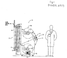
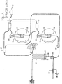
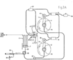
- the present invention has an arrangement generally similar to that illustrated in Figs.1 and 1A of U.S. Patent No. 8,002,024 .
- the identifying element numbers used in the aforementioned patent are also used in the following description for corresponding elements in the present invention where the corresponding elements perform the same, or substantially the same function, and do not form part of the present invention.
- the roll unwind spindles 11 and 12 are controlled in a similar manner and the accumulator 13 has a similar format. However, in the instant invention, the accumulator 13 is mounted above the unwind spindles 11 and 12 which reduces the height of the spindles for easier loading.
- the spindle location may be provided in a variety of alternative formats according to a user's preference and procedures for loading rolls 11a, 12a and accessing the splicing apparatus.
- the function and interaction of the unwind spindles 11, 12, their drives 11d, 12d and brakes 11b and 12b, and accumulator 13 are similar to the description provided at col 3, line 14 - col. 5, line 35, in U.S. Patent No. 8,002,924 .
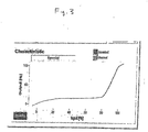
- the current output is used as an input to a Camille BauerTM (Wohlen, Switzerland) SineaxTM TV809 Programmable Isolating Amplifier which provides a programmable output vs. input curve as shown in Fig 3 .
- the SineaxTM output current is used as in input to the disclosed Proportion-Air® air pressure regulator to control air pressure provided to brakes 11b and 12b as disclosed in U.S. Patent No. 8,002,924 .
- the inventive splicing apparatus 4400 of the instant invention shown in Figs. 2 , 2A and 4 is located in a similar orientation to that shown in Fig. 1 of 8,002,924, the splicing apparatus of the present invention is substantially different from the splicing apparatus shown in Figs. 3-6 of US Patent No. 8,002,924 .
- the present invention uses a pair of platens 4401, 4402, as schematically illustrated in Fig. 4 .
- the platens 4401, 4402 extend longitudinally (90 degrees to the plane of the cross sectional view of Fig.
- the crankshafts are linked together with a timing belt and pulleys and may be rotated via a hand crank or may be motor-driven.
- the platens may be cycled or reciprocated via a pneumatic cylinder (not shown) such as provided by Clippard Instrument Laboratory of Cincinnati, OH.
- the space between the platens defines a passageway 4403 through which an expiring web 4404 may pass.
- web 4404 may be comprised of various materials such as paper, poly film, magnetic material, or thin metal foils.
- the reciprocating motion allows the passageway 4403 to be nearly closed and reopened by moving platens 4401 and 4402 from the positions shown in Fig. 4 .
- the platens, cranks, connecting rod and sliders may be swung through about 180 degrees outwards with detents approximately every 90 degrees to allow easier access for an operator to set up for a splice.
- a piece of adhesive tape 4406 is shown in Fig. 4 disposed on the inner surface of platen 4401.
- An adhesive side 4407 of the tape 4406 is facing outwards (or to the left) from platen 4401 and approximately one-half of the tape is adhered to a replenishing web 4405.
- the other half of the tape has its adhesive side 4407 exposed and will be used to join the replenishing web 4405 to web 4404 which is also known as the depleting, or expiring, web or roll web because the source roll 11a from which web 4404 is unwinding and is nearing at its end and it is desirable to attach a new supply of web 4405 from a new source roll 12a as shown in Fig.
- the end of replenishing web 4405 is held in place on platen 4401 by a steel die strip 4409.
- the die strip 4409 is in turn held in place by a series of magnets 4411.
- the size of the magnets may be selected to adjust the magnetic attracting force.
- Holes 4409a may be formed on die strip 4409 with locations corresponding to the location of magnets 4411 as another means of adjusting the magnetic attraction force.
- the magnets are cylindrical and the polarity of the magnets is selected during assembly of the apparatus such that the North pole (for example) of the magnets is facing outward away from die strip 4409 as shown in Fig. 4 .
- a splice may be triggered by known methods: manually by an operator observing that a supply roll is near depletion and then the operator makes the splice by rotating a hand crank through about one turn; semiautomatically by a roll size sensor that signals a visual and or audible alarm when a supply roll is nearly deleted and then an operator makes the splice by rotating a hand crank; or fully automatically where a roll size sensor and control system detects that a supply roll is nearly depleted and triggers a motor drive to rotate the crankshafts.
- crankshafts initiates a splicing cycle by, first, moving the platens 4401 and 4402 inwards toward one another to a stop which causes depleting web 4404 to be momentarily grasped against platen 4401 by an ironing pad 4408 on platen 4402 which presses the depleting web 4404 against the sticky side 4407 of exposed tape 4406 which has been previously adhered (during preparation) to the end of replenishing web 4405.
- a die strip 4409 with a cutting edge 4410 presses on and cuts through the depleting web 4404. The loose end of depleting web 4404 is held in place by the die strip 4409 as will be described.
- Fig. 5 shows the step in the splicing sequence where expiring web 4404 is just contacting ironing pad 4408, but not yet clamped against the adhesive side 4407 of tape 4406.
- Fig. 6 shows a further step in the cycle where the expiring web 4404 is clamped into contact with the adhesive side 4407 of tape 4406, and cutting edge 4410 of die strip 4409 is just about to begin cutting expiring web 4404.
- the platens 4401 and 4402 begin to separate, or open.
- the die strip 4409 separates from platen 4401 because platen 4402 has more powerful magnets 4412 which are offset longitudinally with respect to the plane of the cross section of Fig. 7 so that their central axis is not aligned with the magnets 4411 in the opposing platen 4401.
- the magnets 4411 and 4412 can operate in conjunction with a respective movable member 4418, 4419 such as a Delrin® bar with or without a steel backing.
- the movable members 4418, 4419 can move outwards from the platens 4401, 4402 to improve the transfer of die strip 4409 from one platen to the other.
- a mechanical gripper (not shown) can be used in conjunction with magnets, or without magnets, to hold or transfer the die strip 4409 to or from the first and second platens 4401, 4402.
- the splicing arrangement shown in Figs. 4-7 is for producing a butt splice where the adjacent ends of the depleting web 4404 and the replenishing web 4405 are aligned with one another in a non-overlapping manner.
- the adhesive tape 4406 is attached to aligned surfaces of the depleting web 4404 and the replenishing web 4405.
- Figs. 8 and 9 are directed to the formation of a lap splice where the adjacent ends of the depleting web 4404 and the replenishing web 4405 are arranged in an overlapping manner with the adhesive tape 4420 engaging and coupling together the overlapping end portions of the depleting and replenishing webs.
- an outfeeding end 4404A and an infeeding end 4404B of the depleting web are formed.
- the depleting web's outfeeding end 4404A is attached to the end of the replenishing web 4405 as shown in Fig.9 .
- the depleting web's severed infeeding end 4404B is engaged and collected by die strip 4409.
- the depleting web 4404 is stopped very momentarily during the splice process, however, at typical operation speeds, e.g., up to about 600 fpm or 10 inches/second, this momentary stoppage only causes a shortage of an inch or two of web to the web consuming process downstream of the splicer.
- This relatively minor amount of web interruption is readily accommodated by the accumulator 13 which is normally equipped to deliver web to a web consuming machine such as the Tamarack Vista window applicator which operates in a stop-and-go manner, as disclosed in U.S. Patent No. 6,772,663 and U.S. Patent Application Serial No.
- the replenishing roll 12a needs to accelerate from zero to an average web speed to match the average speed of the web consuming process.
- Unwind drive 12d is sized and adjusted to provide this acceleration, while accumulator 13 cycles to provide the web demanded by the web consuming process.
- the pair of platens 4401, 4402 can be utilized such that the prepared tape 4406 and replenishing web 4405 can first be installed on platen 4401 as described above, and then for a subsequent splice, the die plate 4409 is installed on platen 4402.
- the first depleting roll 11a could be installed on spindle 11 and the replenishing web 12a on spindle 12. While roll 12a is being consumed, the next replenishing roll would be installed on spindle 11. In this manner (which is further described in U.S. Patent No. 8,002,924 ), the splicer 10 can supply web to a web-consuming process without interruption.
- Platens 4401 and 4402 are removable and interchangeable so that splices may be prepared remotely from the splicer assembly 4400 as shown in Figs. 10 and 11 , where the first splicer mechanism 4424 has been swung open (see Fig. 10 ) and platen 4401 has been removed from splicer apparatus 4400 (see Fig. 11 ) to facilitate attachment of replenishing roll 12a to the combination of the first platen, die strip 4409 and adhesive tape 4406.
- the prepared platen 4401 (with replenishing web 4405, adhesive tape 4406 and die member 4409) is then easily installed onto first splicer mechanism 4424 of splicing apparatus 4400 (see Fig.
- Platens 4401 and 4402 may be provided in different widths and offset formats for easier preparation of splices. For example, if the web is only a few inches wide, a narrower platen may be used which will be lighter and easier for an operator to manipulate.
- the first and second platens 4401, 4402 may be held in place in first and second reciprocating splicer mechanisms 4424 and 4425, respectively, in splicer apparatus 4400 with magnets or other retaining means such as mechanical couplers, i.e., spring clip, clamps, wires or Velcro, to provide for tool-less installation and removal.
- magnets or other retaining means such as mechanical couplers, i.e., spring clip, clamps, wires or Velcro, to provide for tool-less installation and removal.
- a compound-hinged flap with a ruler scale on one side and a non-stick surface such as provided by tesa® (Hamburg, Germany) Printer's Friend® 4863 tape on the other side can be used during splice preparation to laterally position the end of replenishing web 4405 by using the ruler side and then by swinging the door though about 180 degrees so that the adhesive tape 4406 is held against platen 4401. Once the die strip 4409 is placed into position on the end of replenishing web 4405, the door is swung about 180 degrees to the opposite side of the platen so that it does not interfere with the splicing process.
- the invention generally refers to a splicing apparatus for replacing an expiring web from an expiring roll of web material with a replenishing web from a replenishing roll of web material, said apparatus comprising:
- said retaining means is magnetic.
- said magnetic retaining means includes at least one magnet disposed in each of said first and second platens, and said die member is comprised of a magnetic responsive material.
- said die member is comprised of steel.
- each of said magnets includes north and south poles, with the north pole of each magnet facing outwardly away from said die member.
- a magnetic attraction of said at least one magnet in said second platen exerted on said die member can be greater than a magnetic attraction of said at least one magnet in said first platen exerted on said die member to allow said die member to be released from said first platen followed by attachment of said die member to said second platen during replacement of the expiring web with the replenishing web.
- said apparatus can comprise means within said die member for changing the respective magnetic attractions of the magnets in said first and second platens exerted on said die member to transfer said die member from said first platen to said second platen.
- said means for changing the magnetic attractions of said first and second platens exerted on said die member can include one or more spaced apertures within said die member.
- the step of changing the magnetic attraction of said first and second platens exerted on said die member can optionally include changing the size of a single aperture disposed in said die member or changing the number of plural apertures in said die member disposed between said first and second platens.
- the transfer of said die member from said first platen to said second platen occurs when said expiring and replenishing webs are spliced together.
- said retaining means can include mechanical couplers for attaching said first and second platens to said die member.
- each of said mechanical couplers can attach said first and second platens to said die member in a releasable manner.
- said mechanical couplers can include spring clips, clamps, wire or Velcro.
- the apparatus optionally further comprises first and second drive means respectively coupled to said first and second platens for linearly displacing said platens toward and away from one another in a reciprocating manner during splicing of the replenishing and expiring webs.
- each of said first and second drive means can include a respective combination of a crankshaft, a connecting rod and a slider mechanism.
- the apparatus may further comprise a timing belt and pulley combination coupling said crankshafts together to synchronize movement of said first and second platens.
- the apparatus may further comprise a hand crank or a motor coupled to said timing belt and pulley combination for manually or automatically rotationally displacing said crank shafts.
- the said first and second drive means can include respective first and second pneumatic cylinders for linearly displacing said platens toward and away from one another in a reciprocating manner.
- said passageway defined by said first and second platens alternately widens and narrows during splicing of the replenishing and expiring webs.
- said first and second platens are in close proximity to one another during splicing of the replenishing and expiring webs.
- the replenishing and expiring webs can be comprised of paper, poly film, magnetic or thin metal foil materials. Additionally, or alternatively, said adhesive member may initially extend beyond the end of the replenishing web in forming a non-overlapping butt splice between the replenishing and expiring rolls of web material.
- said adhesive member can initially extend only over a portion of said first platen so as to form an overlapping splice between the replenishing and expiring webs.
- the invention also refers in general to a method for splicing an expiring web from an expiring roll of web material to a replenishing web from a replenishing roll of web material, said method comprising the steps of:
- the method may optionally further comprise at least one of the following steps, i.e. one or all of the following optional steps in any possible combination: The step of providing a metal die member and transferring said die member from said first platen to said second platen using a magnetic field.
- the step of initiating a second splicing of a replenishing web to a second expiring web by attaching a second replenishing web to said second platen, wherein said replenishing and expiring webs optionally can be initially disposed in an aligned, spaced manner along their respective lengths so as to form a butt splice. Additionally, or alternatively, said replenishing and expiring webs can be initially disposed in an overlapping manner so as to form a lap splice.
- said first and second platens can be installed in a splicing apparatus.
- said die member can engage and maintain the severed infeeding end of said expiring web in secure contact with said second platen for separating and holding said severed infeeding end from the spliced expiring and replenishing webs.
Landscapes
- Engineering & Computer Science (AREA)
- Mechanical Engineering (AREA)
- Replacement Of Web Rolls (AREA)
Claims (17)
- Spleißvorrichtung (4400) zum Ersetzen eines auslaufenden Gewebes (4404) von einer auslaufenden Rolle von Gewebematerial mit einem Wiederauffüllungsgewebe (4405) von einer Wiederauffüllungsrolle von Gewebematerial, wobei die Vorrichtung umfasst:erste und zweite Walzen (4401, 4402), angeordnet in einer räumlich voneinander beabstandeten Weise, um einen Durchgang (4403) zwischen den ersten und zweiten Walzen zu definieren, wobei das auslaufende Gewebe (4404) zwischen den Walzen durch den Durchgang gerichtet ist, und wobei die Walzen eingerichtet sind zum Versatz in Richtung auf und weg von einander in einer hin- und her bewegenden Weise (4414, 4415);ein Haftelement (4406), befestigt an dem Wiederauffüllungsgewebe (4405) in Gegenüberstellung mit der zweiten Walze (4402), wobei das Haftelement eingerichtet ist, um das Wiederauffüllungsgewebe an dem auslaufenden Gewebe (4404) in Eingriff zu bringen und zu befestigen;ein Matrizenelement (4409), das einen Schneidabschnitt (4410) und einen Klemmabschnitt hat;Rückhaltemittel (4411), befestigt an der ersten Walze (4401) zum anfänglichen Befestigen des Matrizenelements (4409) an der ersten Walze in einer lösbaren Weise, während das Wiederauffüllungsgewebe an die erste Walze mit dem Klemmabschnitt des Matrizenelements geklemmt wird; undein Polsterelement (4408), angeordnet auf der zweiten Walze (4402) in Gegenüberstellung mit der ersten Walze (4401) und eingerichtet, um das auslaufende Gewebe (4404) in Richtung auf die erste Walze in Eingriff zu bringen und zu zwingen, das den Durchgang (4403) zwischen den Walzen durchläuft, wenn die Walzen in Richtung auf einander versetzt sind, sodass eine erste Oberfläche des auslaufenden Gewebes in intimen Kontakt mit dem Polsterelement und eine zweite entgegengesetzte Oberfläche des auslaufenden Gewebes in Kontakt mit dem Haftelement (4406) und der Schneidkante (4410) des Matrizenelements platziert wird, um das auslaufende Gewebe zu durchtrennen und das Auslaufende des auslaufenden Gewebes an das Wiederauffüllungsgewebe mittels des Haftelements durch Spleißen der auslaufenden und Weiderauffüllungs- Gewebe aneinander zu befestigen, und wobei die Rückhaltemittel (4411) das Matrizenelement (4409) von der ersten Walze lösen und dadurch das Wiederauffüllungsgewebe von der ersten Walze zu befreien und das Matrizenelement an der zweiten Walze zum in Eingriff Bringen und Klemmen eines durchtrennten Einzugsendes des auslaufenden Gewebes an der zweiten Walze zu befestigen.
- Vorrichtung nach Anspruch 1, wobei die Rückhaltemittel (4411) magnetisch sind.
- Vorrichtung nach Anspruch 2, wobei die magnetischen Rückhaltemittel mindestens einen Magneten (4411, 4412) einschließen, der in jeder der ersten und zweiten Walzen (4401, 4402) angeordnet ist und wobei das Matrizenelement (4409) von einem magnetisch reagierenden Material umfasst ist.
- Vorrichtung nach Anspruch 3, wobei eine magnetische Anziehung des mindestens einen Magneten (4412) in der zweiten Walze (4402), die auf das Matrizenelement (4409) ausgeübt wird, größer ist als eine magnetische Anziehung des mindestens einen Magneten (4411) in der ersten Walze (4401), die auf das Matrizenelement ausgeübt wird, um dem Matrizenelement zu erlauben, von der ersten Walze gelöst zu werden, gefolgt durch Befestigung des Matrizenelements an der zweiten Walze während des Ersetzens des auslaufenden Gewebes (4404) mit dem Wiederauffüllungsgewebe (4405).
- Vorrichtung nach Anspruch 4, weiter umfassend Mittel (4409a) innerhalb des Matrizenelements (4409) zum Wechseln der entsprechenden magnetischen Anziehungen der Magneten in den ersten und zweiten Walzen (4401), (4402), die auf das Matrizenelement ausgeübt werden, um das Matrizenelement von der ersten Walze zu der zweiten Walze zu überführen.
- Vorrichtung nach Anspruch 5, wobei die Mittel zum Wechseln der magnetischen Anziehungen der ersten und zweiten Walzen (4401, 4402), die auf das Matrizen-(4409) -element ausgeübt werden, eine oder mehrere räumlich beabstandete Aperturen (4409a) innerhalb des Matrizenelements einschließen.
- Vorrichtung nach Anspruch 6, wobei der Schritt des Wechselns der magnetischen Anziehung der ersten und zweiten Walzen, die auf das Matrizenelement (4409) ausgeübt wird, Wechseln der Größe einer einzigen Apertur (4409a), die in dem Matrizenelement angeordnet ist, oder Wechseln der Anzahl der mehreren Aperturen (4409a) in dem Matrizenelement, angeordnet zwischen den ersten und zweiten Walzen, einschließt.
- Vorrichtung nach einem der Ansprüche 1 bis 7, wobei die Rückhaltemittel mechanische Koppler zum Befestigen der ersten und zweiten Walzen an dem Matrizenelement umfassen.
- Vorrichtung nach Anspruch 8, wobei jeder der mechanischen Koppler die ersten und zweiten Walzen an dem Matrizenelement in einer lösbaren Weise befestigt.
- Vorrichtung nach einem der Ansprüche 1 bis 9, weiter umfassend erste und zweite Antriebsmittel (4426, 4427), entsprechend gekoppelt mit den ersten und zweiten Walzen (4401, 4402), zum linearen Versetzen der Walzen in Richtung auf und weg von einander in einer hin und her bewegenden Weise während des Spleißens der Wiederauffüllungs- und auslaufenden Gewebe.
- Vorrichtung nach einem der Ansprüche 1 bis 10, wobei der Durchgang (4403), definiert zwischen den ersten und zweiten Walzen (4401, 4402), sich alternierend weitet und verengt während des Spleißens der Weiderauffüllungs- und auslaufenden Gewebe.
- Vorrichtung nach einem der Ansprüche 1 bis 11, wobei das Haftelement (4406) sich anfänglich über das Ende des Wiederauffüllungsgewebes (4405) erstreckt beim Bilden einer nicht überlappenden Stumpfnaht zwischen den Wiederauffüllungs- und auslaufenden Rollen von Gewebematerial.
- Vorrichtung nach einem der Ansprüche 1 bis 12, wobei das Haftelement (4422) sich anfänglich über einen Abschnitt der ersten Walze (4401) erstreckt, um eine überlappende Naht zwischen den Wiederauffüllungs- und auslaufenden Geweben zu bilden.
- Verfahren zum Spleißen eines auslaufenden Gewebes (4404) von einer auslaufenden Rolle von Gewebematerial an ein Wiederauffüllungsgewebe (4405) von einer Wiederauffüllungsrolle von Gewebematerial, wobei das Verfahren die folgenden Schritte umfasst:Versetzen des auslaufenden Gewebes (4404) entlang seiner Länge zwischen ersten und zweiten Walzen (4401, 4402);Positionieren eines Endes des Wiederauffüllungsgewebes (4405) auf einer inneren Oberfläche der ersten Walze (4401) in Gegenüberstellung mit der zweiten Walze (4402);Befestigen eines Matrizenelements (4409), das einen Schneidabschnitt (4410) und einen Klemmabschnitt hat, an der ersten Walze, sodass das Ende des Wiederauffüllungsgewebes dazwischen angeordnet ist und in Eingriff mittels des Matrizenelements und der ersten Walze gebracht ist;Bereitstellen eines Polsterelements (4408) auf einer inneren Oberfläche der zweiten Walze in Gegenüberstellung mit der ersten Walze;Versetzen der ersten und zweiten Walzen (4401, 4402) in Richtung auf einander mit dem sich bewegenden auslaufenden Gewebe (4404), angeordnet in Gegenüberstellung mit und zwischen den entsprechenden inneren Oberflächen der ersten und zweiten Walzen;Anbringen des Endes des Wiederauffüllungsgewebes (4405) an dem sich bewegenden auslaufenden Gewebe;Durchtrennen des auslaufenden Gewebes (4404) mit dem Schneidabschnitt (4410) des Matrizenelements beim Bilden eines Auslaufendes und eines Einzugsendes des auslaufenden Gewebes;Überführen des Matrizenelements (4409) von der ersten Walze (4401) zu der zweiten Walze (4402) beim Befreien des Wiederauffüllungsgewebes von der ersten Walze und in Eingriff Bringen und Halten des durchtrennten Einzugsendes des auslaufenden Gewebes an die zweite Walze; undVersetzen der ersten und zweiten Walzen weg von einander, was dem auslaufenden Gewebe (4404) und dem Wiederauffüllungsgewebe (4405), befestigt an dem Auslaufende des auslaufenden Gewebes, erlaubt, zwischen den ersten und zweiten Walzen auszutreten.
- Verfahren nach Anspruch 14, weiter umfassend den Schritt des Bereitstellens eines metallischen Matrizenelements (4409) und Überführen des Matrizenelements von der ersten Walze zu der zweiten Walze unter Verwendung eines Magnetfelds.
- Verfahren nach Anspruch 14 oder 15, wobei die ersten und zweiten Walzen in einer Spleißvorrichtung (4400) installiert sind, wobei das Verfahren weiter den Schritt des Entfernens der ersten Walze (4401) von der Spleißvorrichtung umfasst, um Befestigen eines Wiederauffüllungsgewebes (4405) an der ersten Walze und Ersetzen der ersten Walze in der Spleißvorrichtung zu erleichtern.
- Verfahren nach einem der Ansprüche 14 bis 16, weiter umfassend den Schritt des Bereitstellens eines neuen Wiederherstellungsgewebes für die zweite Walze (4402) und Bereitstellen des Matrizenelements (4409) an die zweite Walze, wenn ein originales Wiederauffüllungsgewebe (4405) ersetzt wird.
Applications Claiming Priority (1)
| Application Number | Priority Date | Filing Date | Title |
|---|---|---|---|
| US201462048064P | 2014-09-09 | 2014-09-09 |
Publications (3)
| Publication Number | Publication Date |
|---|---|
| EP2998253A2 EP2998253A2 (de) | 2016-03-23 |
| EP2998253A3 EP2998253A3 (de) | 2016-05-04 |
| EP2998253B1 true EP2998253B1 (de) | 2018-12-05 |
Family
ID=54145588
Family Applications (1)
| Application Number | Title | Priority Date | Filing Date |
|---|---|---|---|
| EP15184438.8A Active EP2998253B1 (de) | 2014-09-09 | 2015-09-09 | Walzenblechklebevorrichtung und -verfahren |
Country Status (2)
| Country | Link |
|---|---|
| US (1) | US9670022B2 (de) |
| EP (1) | EP2998253B1 (de) |
Families Citing this family (14)
| Publication number | Priority date | Publication date | Assignee | Title |
|---|---|---|---|---|
| US20140196405A1 (en) * | 2013-01-14 | 2014-07-17 | Sunbeam Products, Inc. | Vacuum Sealer with a Retractable Heater Bar |
| CN106144718B (zh) * | 2016-08-29 | 2024-06-18 | 华周(福建)机械有限公司 | 一种包装纸复合机纸张自动平接接料装置 |
| US10457512B2 (en) | 2016-09-19 | 2019-10-29 | New Era Converting Machinery, Inc. | Automatic lapless butt material splice |
| JP7065555B2 (ja) * | 2018-03-27 | 2022-05-12 | 日東電工株式会社 | 粘着テープ接合装置 |
| DE102019203742A1 (de) * | 2019-02-07 | 2020-08-13 | Bhs Corrugated Maschinen- Und Anlagenbau Gmbh | Materialbahn-Einzugsvorrichtung |
| DE102019201601A1 (de) * | 2019-02-07 | 2020-08-13 | Bhs Intralogistics Gmbh | Materialrollen-Vorbereitungsanordnung |
| DE102019122312B4 (de) * | 2019-08-20 | 2022-12-22 | Voith Patent Gmbh | Bahnhaltevorrichtung |
| EP3967637B1 (de) * | 2020-09-14 | 2023-11-29 | Harro Höfliger Verpackungsmaschinen GmbH | Vorrichtung und verfahren zum spleissen und kontinuierlichen bereitstellen einer folienbahn |
| CN112297446A (zh) * | 2020-10-09 | 2021-02-02 | 孙立明 | 一种用于石墨烯芯片加工的条带连接装置 |
| KR102858408B1 (ko) * | 2021-02-26 | 2025-09-10 | 에스케이온 주식회사 | 공급소재 자동교체장치 및 자동교체방법 |
| CN113291900B (zh) * | 2021-04-22 | 2023-03-24 | 金东纸业(江苏)股份有限公司 | 一种接纸装置及复卷机 |
| FI129673B (en) * | 2021-06-15 | 2022-06-30 | Valmet Technologies Oy | A method and a device for joining ends of fiber webs in a parent roll change of an unwinder |
| CA3233530C (en) | 2022-08-31 | 2025-06-10 | Abzac Canada Inc. | Splicing apparatus and method for a paperboard protective corner manufacturing system |
| US20250011120A1 (en) * | 2023-07-05 | 2025-01-09 | Sk On Co., Ltd. | Separator supply device and separator supply method |
Family Cites Families (7)
| Publication number | Priority date | Publication date | Assignee | Title |
|---|---|---|---|---|
| GB1199922A (en) | 1966-08-01 | 1970-07-22 | Graham Archie Bruce Byrt | Improvements in Apparatus for Butt-Splicing Webs |
| US4923546A (en) * | 1986-09-12 | 1990-05-08 | Martin Automatic Inc. | Method and apparatus for forming a butt splice |
| US5827166A (en) | 1993-12-16 | 1998-10-27 | Philip Morris Incorporated | Device for joining strips of a flexible material |
| US6772663B2 (en) | 2001-04-20 | 2004-08-10 | Tamarack Products, Inc. | Apparatus and method for rotary pressure cutting |
| DE112005000423T5 (de) | 2004-03-23 | 2007-03-01 | Showa Denko K.K. | Wärmetauscher |
| US8002924B2 (en) | 2009-01-27 | 2011-08-23 | Tamarack Products, Inc. | Apparatus for splicing webs |
| US20110245056A1 (en) | 2010-03-31 | 2011-10-06 | Tamarack Products, Inc. | Rigid window applicator and method |
-
2015
- 2015-09-03 US US14/844,836 patent/US9670022B2/en active Active
- 2015-09-09 EP EP15184438.8A patent/EP2998253B1/de active Active
Non-Patent Citations (1)
| Title |
|---|
| None * |
Also Published As
| Publication number | Publication date |
|---|---|
| US9670022B2 (en) | 2017-06-06 |
| US20160068361A1 (en) | 2016-03-10 |
| EP2998253A3 (de) | 2016-05-04 |
| EP2998253A2 (de) | 2016-03-23 |
Similar Documents
| Publication | Publication Date | Title |
|---|---|---|
| EP2998253B1 (de) | Walzenblechklebevorrichtung und -verfahren | |
| US5431767A (en) | Apparatus for applying adhesive tape | |
| US8002924B2 (en) | Apparatus for splicing webs | |
| JPS6353094B2 (de) | ||
| JPH06278918A (ja) | ウエブ材料のログを製造するとともに各ログの巻取り完了時にウエブ材料を切断する方法および装置 | |
| JPH0940270A (ja) | 粘着テープ供給装置 | |
| JP4136864B2 (ja) | ウェブ巻替え装置及び方法 | |
| JPH05299277A (ja) | 巻鉄心用帯材の切り抜き装置 | |
| FI105671B (fi) | Lieriörullauskone | |
| US4720320A (en) | Apparatus for splicing a trailing end of a web from a depleted coil to the leading end of a fresh coil | |
| US4512506A (en) | System for the supply of staple wire to a stapler | |
| US8500057B2 (en) | Method and apparatus for threading a fibrous material web in a winder | |
| EP1648805B1 (de) | Verfahren und vorrichtung zum spleissen von bahnen | |
| JP3649755B2 (ja) | 本表紙を機械的に製造するための背心を所定長に裁断して表紙と接合する装置 | |
| CN1191178C (zh) | 生产有外皮的包装件的方法和装置 | |
| US12017878B2 (en) | Method and device for successively winding a film web, and film roll | |
| JP2007261774A (ja) | タブ付きテープ貼付装置 | |
| US7341217B2 (en) | Electrostatic tension control of webs | |
| US20070157777A1 (en) | Device and method for preparing a piece of adhesive tape of desired length from a reel | |
| JPH07101610A (ja) | 両面粘着テープの自動供給取付装置 | |
| JP2725056B2 (ja) | シート分割巻取装置の巻取準備装置 | |
| CN114670460B (zh) | 送纸单元、裁切单元以及单张塑封装置 | |
| US20180050827A1 (en) | System, apparatus and method of placing an insert in a bag | |
| JP7278935B2 (ja) | テープ貼付装置 | |
| JPH0648383Y2 (ja) | 顕微鏡標本作成装置に於けるカバー片の供給装置 |
Legal Events
| Date | Code | Title | Description |
|---|---|---|---|
| PUAI | Public reference made under article 153(3) epc to a published international application that has entered the european phase |
Free format text: ORIGINAL CODE: 0009012 |
|
| AK | Designated contracting states |
Kind code of ref document: A2 Designated state(s): AL AT BE BG CH CY CZ DE DK EE ES FI FR GB GR HR HU IE IS IT LI LT LU LV MC MK MT NL NO PL PT RO RS SE SI SK SM TR |
|
| AX | Request for extension of the european patent |
Extension state: BA ME |
|
| PUAL | Search report despatched |
Free format text: ORIGINAL CODE: 0009013 |
|
| AK | Designated contracting states |
Kind code of ref document: A3 Designated state(s): AL AT BE BG CH CY CZ DE DK EE ES FI FR GB GR HR HU IE IS IT LI LT LU LV MC MK MT NL NO PL PT RO RS SE SI SK SM TR |
|
| AX | Request for extension of the european patent |
Extension state: BA ME |
|
| RIC1 | Information provided on ipc code assigned before grant |
Ipc: B65H 19/18 20060101AFI20160330BHEP Ipc: B65H 19/20 20060101ALI20160330BHEP |
|
| STAA | Information on the status of an ep patent application or granted ep patent |
Free format text: STATUS: REQUEST FOR EXAMINATION WAS MADE |
|
| 17P | Request for examination filed |
Effective date: 20161028 |
|
| RBV | Designated contracting states (corrected) |
Designated state(s): AL AT BE BG CH CY CZ DE DK EE ES FI FR GB GR HR HU IE IS IT LI LT LU LV MC MK MT NL NO PL PT RO RS SE SI SK SM TR |
|
| GRAP | Despatch of communication of intention to grant a patent |
Free format text: ORIGINAL CODE: EPIDOSNIGR1 |
|
| STAA | Information on the status of an ep patent application or granted ep patent |
Free format text: STATUS: GRANT OF PATENT IS INTENDED |
|
| RIC1 | Information provided on ipc code assigned before grant |
Ipc: B65H 19/18 20060101AFI20180606BHEP Ipc: B29C 65/00 20060101ALI20180606BHEP Ipc: B65H 21/00 20060101ALI20180606BHEP Ipc: B31F 5/04 20060101ALI20180606BHEP Ipc: B65H 19/20 20060101ALI20180606BHEP Ipc: B29C 65/48 20060101ALI20180606BHEP |
|
| INTG | Intention to grant announced |
Effective date: 20180628 |
|
| GRAS | Grant fee paid |
Free format text: ORIGINAL CODE: EPIDOSNIGR3 |
|
| GRAA | (expected) grant |
Free format text: ORIGINAL CODE: 0009210 |
|
| STAA | Information on the status of an ep patent application or granted ep patent |
Free format text: STATUS: THE PATENT HAS BEEN GRANTED |
|
| AK | Designated contracting states |
Kind code of ref document: B1 Designated state(s): AL AT BE BG CH CY CZ DE DK EE ES FI FR GB GR HR HU IE IS IT LI LT LU LV MC MK MT NL NO PL PT RO RS SE SI SK SM TR |
|
| REG | Reference to a national code |
Ref country code: GB Ref legal event code: FG4D |
|
| REG | Reference to a national code |
Ref country code: CH Ref legal event code: EP |
|
| REG | Reference to a national code |
Ref country code: AT Ref legal event code: REF Ref document number: 1072779 Country of ref document: AT Kind code of ref document: T Effective date: 20181215 |
|
| REG | Reference to a national code |
Ref country code: DE Ref legal event code: R096 Ref document number: 602015020761 Country of ref document: DE |
|
| REG | Reference to a national code |
Ref country code: IE Ref legal event code: FG4D |
|
| REG | Reference to a national code |
Ref country code: CH Ref legal event code: NV Representative=s name: VALIPAT S.A. GEVERS SA, CH |
|
| REG | Reference to a national code |
Ref country code: CH Ref legal event code: PCAR Free format text: NEW ADDRESS: RUE DES NOYERS 11, 2000 NEUCHATEL (CH) |
|
| REG | Reference to a national code |
Ref country code: NL Ref legal event code: MP Effective date: 20181205 |
|
| REG | Reference to a national code |
Ref country code: AT Ref legal event code: MK05 Ref document number: 1072779 Country of ref document: AT Kind code of ref document: T Effective date: 20181205 |
|
| REG | Reference to a national code |
Ref country code: LT Ref legal event code: MG4D |
|
| PG25 | Lapsed in a contracting state [announced via postgrant information from national office to epo] |
Ref country code: ES Free format text: LAPSE BECAUSE OF FAILURE TO SUBMIT A TRANSLATION OF THE DESCRIPTION OR TO PAY THE FEE WITHIN THE PRESCRIBED TIME-LIMIT Effective date: 20181205 Ref country code: LV Free format text: LAPSE BECAUSE OF FAILURE TO SUBMIT A TRANSLATION OF THE DESCRIPTION OR TO PAY THE FEE WITHIN THE PRESCRIBED TIME-LIMIT Effective date: 20181205 Ref country code: AT Free format text: LAPSE BECAUSE OF FAILURE TO SUBMIT A TRANSLATION OF THE DESCRIPTION OR TO PAY THE FEE WITHIN THE PRESCRIBED TIME-LIMIT Effective date: 20181205 Ref country code: FI Free format text: LAPSE BECAUSE OF FAILURE TO SUBMIT A TRANSLATION OF THE DESCRIPTION OR TO PAY THE FEE WITHIN THE PRESCRIBED TIME-LIMIT Effective date: 20181205 Ref country code: NO Free format text: LAPSE BECAUSE OF FAILURE TO SUBMIT A TRANSLATION OF THE DESCRIPTION OR TO PAY THE FEE WITHIN THE PRESCRIBED TIME-LIMIT Effective date: 20190305 Ref country code: HR Free format text: LAPSE BECAUSE OF FAILURE TO SUBMIT A TRANSLATION OF THE DESCRIPTION OR TO PAY THE FEE WITHIN THE PRESCRIBED TIME-LIMIT Effective date: 20181205 Ref country code: LT Free format text: LAPSE BECAUSE OF FAILURE TO SUBMIT A TRANSLATION OF THE DESCRIPTION OR TO PAY THE FEE WITHIN THE PRESCRIBED TIME-LIMIT Effective date: 20181205 Ref country code: BG Free format text: LAPSE BECAUSE OF FAILURE TO SUBMIT A TRANSLATION OF THE DESCRIPTION OR TO PAY THE FEE WITHIN THE PRESCRIBED TIME-LIMIT Effective date: 20190305 |
|
| PG25 | Lapsed in a contracting state [announced via postgrant information from national office to epo] |
Ref country code: GR Free format text: LAPSE BECAUSE OF FAILURE TO SUBMIT A TRANSLATION OF THE DESCRIPTION OR TO PAY THE FEE WITHIN THE PRESCRIBED TIME-LIMIT Effective date: 20190306 Ref country code: SE Free format text: LAPSE BECAUSE OF FAILURE TO SUBMIT A TRANSLATION OF THE DESCRIPTION OR TO PAY THE FEE WITHIN THE PRESCRIBED TIME-LIMIT Effective date: 20181205 Ref country code: AL Free format text: LAPSE BECAUSE OF FAILURE TO SUBMIT A TRANSLATION OF THE DESCRIPTION OR TO PAY THE FEE WITHIN THE PRESCRIBED TIME-LIMIT Effective date: 20181205 Ref country code: RS Free format text: LAPSE BECAUSE OF FAILURE TO SUBMIT A TRANSLATION OF THE DESCRIPTION OR TO PAY THE FEE WITHIN THE PRESCRIBED TIME-LIMIT Effective date: 20181205 |
|
| PG25 | Lapsed in a contracting state [announced via postgrant information from national office to epo] |
Ref country code: NL Free format text: LAPSE BECAUSE OF FAILURE TO SUBMIT A TRANSLATION OF THE DESCRIPTION OR TO PAY THE FEE WITHIN THE PRESCRIBED TIME-LIMIT Effective date: 20181205 |
|
| PG25 | Lapsed in a contracting state [announced via postgrant information from national office to epo] |
Ref country code: PT Free format text: LAPSE BECAUSE OF FAILURE TO SUBMIT A TRANSLATION OF THE DESCRIPTION OR TO PAY THE FEE WITHIN THE PRESCRIBED TIME-LIMIT Effective date: 20190405 Ref country code: CZ Free format text: LAPSE BECAUSE OF FAILURE TO SUBMIT A TRANSLATION OF THE DESCRIPTION OR TO PAY THE FEE WITHIN THE PRESCRIBED TIME-LIMIT Effective date: 20181205 Ref country code: PL Free format text: LAPSE BECAUSE OF FAILURE TO SUBMIT A TRANSLATION OF THE DESCRIPTION OR TO PAY THE FEE WITHIN THE PRESCRIBED TIME-LIMIT Effective date: 20181205 Ref country code: IT Free format text: LAPSE BECAUSE OF FAILURE TO SUBMIT A TRANSLATION OF THE DESCRIPTION OR TO PAY THE FEE WITHIN THE PRESCRIBED TIME-LIMIT Effective date: 20181205 |
|
| PG25 | Lapsed in a contracting state [announced via postgrant information from national office to epo] |
Ref country code: SK Free format text: LAPSE BECAUSE OF FAILURE TO SUBMIT A TRANSLATION OF THE DESCRIPTION OR TO PAY THE FEE WITHIN THE PRESCRIBED TIME-LIMIT Effective date: 20181205 Ref country code: RO Free format text: LAPSE BECAUSE OF FAILURE TO SUBMIT A TRANSLATION OF THE DESCRIPTION OR TO PAY THE FEE WITHIN THE PRESCRIBED TIME-LIMIT Effective date: 20181205 Ref country code: IS Free format text: LAPSE BECAUSE OF FAILURE TO SUBMIT A TRANSLATION OF THE DESCRIPTION OR TO PAY THE FEE WITHIN THE PRESCRIBED TIME-LIMIT Effective date: 20190405 Ref country code: EE Free format text: LAPSE BECAUSE OF FAILURE TO SUBMIT A TRANSLATION OF THE DESCRIPTION OR TO PAY THE FEE WITHIN THE PRESCRIBED TIME-LIMIT Effective date: 20181205 Ref country code: SM Free format text: LAPSE BECAUSE OF FAILURE TO SUBMIT A TRANSLATION OF THE DESCRIPTION OR TO PAY THE FEE WITHIN THE PRESCRIBED TIME-LIMIT Effective date: 20181205 |
|
| REG | Reference to a national code |
Ref country code: DE Ref legal event code: R097 Ref document number: 602015020761 Country of ref document: DE |
|
| PLBE | No opposition filed within time limit |
Free format text: ORIGINAL CODE: 0009261 |
|
| STAA | Information on the status of an ep patent application or granted ep patent |
Free format text: STATUS: NO OPPOSITION FILED WITHIN TIME LIMIT |
|
| PG25 | Lapsed in a contracting state [announced via postgrant information from national office to epo] |
Ref country code: SI Free format text: LAPSE BECAUSE OF FAILURE TO SUBMIT A TRANSLATION OF THE DESCRIPTION OR TO PAY THE FEE WITHIN THE PRESCRIBED TIME-LIMIT Effective date: 20181205 Ref country code: DK Free format text: LAPSE BECAUSE OF FAILURE TO SUBMIT A TRANSLATION OF THE DESCRIPTION OR TO PAY THE FEE WITHIN THE PRESCRIBED TIME-LIMIT Effective date: 20181205 |
|
| 26N | No opposition filed |
Effective date: 20190906 |
|
| PG25 | Lapsed in a contracting state [announced via postgrant information from national office to epo] |
Ref country code: TR Free format text: LAPSE BECAUSE OF FAILURE TO SUBMIT A TRANSLATION OF THE DESCRIPTION OR TO PAY THE FEE WITHIN THE PRESCRIBED TIME-LIMIT Effective date: 20181205 |
|
| PG25 | Lapsed in a contracting state [announced via postgrant information from national office to epo] |
Ref country code: MC Free format text: LAPSE BECAUSE OF FAILURE TO SUBMIT A TRANSLATION OF THE DESCRIPTION OR TO PAY THE FEE WITHIN THE PRESCRIBED TIME-LIMIT Effective date: 20181205 |
|
| PG25 | Lapsed in a contracting state [announced via postgrant information from national office to epo] |
Ref country code: LU Free format text: LAPSE BECAUSE OF NON-PAYMENT OF DUE FEES Effective date: 20190909 Ref country code: IE Free format text: LAPSE BECAUSE OF NON-PAYMENT OF DUE FEES Effective date: 20190909 |
|
| REG | Reference to a national code |
Ref country code: BE Ref legal event code: MM Effective date: 20190930 |
|
| PG25 | Lapsed in a contracting state [announced via postgrant information from national office to epo] |
Ref country code: BE Free format text: LAPSE BECAUSE OF NON-PAYMENT OF DUE FEES Effective date: 20190930 |
|
| PG25 | Lapsed in a contracting state [announced via postgrant information from national office to epo] |
Ref country code: FR Free format text: LAPSE BECAUSE OF NON-PAYMENT OF DUE FEES Effective date: 20190930 |
|
| PG25 | Lapsed in a contracting state [announced via postgrant information from national office to epo] |
Ref country code: CY Free format text: LAPSE BECAUSE OF FAILURE TO SUBMIT A TRANSLATION OF THE DESCRIPTION OR TO PAY THE FEE WITHIN THE PRESCRIBED TIME-LIMIT Effective date: 20181205 |
|
| PG25 | Lapsed in a contracting state [announced via postgrant information from national office to epo] |
Ref country code: HU Free format text: LAPSE BECAUSE OF FAILURE TO SUBMIT A TRANSLATION OF THE DESCRIPTION OR TO PAY THE FEE WITHIN THE PRESCRIBED TIME-LIMIT; INVALID AB INITIO Effective date: 20150909 Ref country code: MT Free format text: LAPSE BECAUSE OF FAILURE TO SUBMIT A TRANSLATION OF THE DESCRIPTION OR TO PAY THE FEE WITHIN THE PRESCRIBED TIME-LIMIT Effective date: 20181205 |
|
| PG25 | Lapsed in a contracting state [announced via postgrant information from national office to epo] |
Ref country code: MK Free format text: LAPSE BECAUSE OF FAILURE TO SUBMIT A TRANSLATION OF THE DESCRIPTION OR TO PAY THE FEE WITHIN THE PRESCRIBED TIME-LIMIT Effective date: 20181205 |
|
| REG | Reference to a national code |
Ref country code: CH Ref legal event code: U11 Free format text: ST27 STATUS EVENT CODE: U-0-0-U10-U11 (AS PROVIDED BY THE NATIONAL OFFICE) Effective date: 20251001 |
|
| PGFP | Annual fee paid to national office [announced via postgrant information from national office to epo] |
Ref country code: DE Payment date: 20250929 Year of fee payment: 11 |
|
| PGFP | Annual fee paid to national office [announced via postgrant information from national office to epo] |
Ref country code: GB Payment date: 20250929 Year of fee payment: 11 |
|
| PGFP | Annual fee paid to national office [announced via postgrant information from national office to epo] |
Ref country code: CH Payment date: 20251001 Year of fee payment: 11 |