EP2995928B1 - Viskosimeter - Google Patents
Viskosimeter Download PDFInfo
- Publication number
- EP2995928B1 EP2995928B1 EP15184091.5A EP15184091A EP2995928B1 EP 2995928 B1 EP2995928 B1 EP 2995928B1 EP 15184091 A EP15184091 A EP 15184091A EP 2995928 B1 EP2995928 B1 EP 2995928B1
- Authority
- EP
- European Patent Office
- Prior art keywords
- hollow cylinder
- rotor
- base frame
- stator
- viscometer according
- Prior art date
- Legal status (The legal status is an assumption and is not a legal conclusion. Google has not performed a legal analysis and makes no representation as to the accuracy of the status listed.)
- Active
Links
Images

Classifications
-
- G—PHYSICS
- G01—MEASURING; TESTING
- G01N—INVESTIGATING OR ANALYSING MATERIALS BY DETERMINING THEIR CHEMICAL OR PHYSICAL PROPERTIES
- G01N11/00—Investigating flow properties of materials, e.g. viscosity, plasticity; Analysing materials by determining flow properties
- G01N11/10—Investigating flow properties of materials, e.g. viscosity, plasticity; Analysing materials by determining flow properties by moving a body within the material
- G01N11/14—Investigating flow properties of materials, e.g. viscosity, plasticity; Analysing materials by determining flow properties by moving a body within the material by using rotary bodies, e.g. vane
-
- H—ELECTRICITY
- H02—GENERATION; CONVERSION OR DISTRIBUTION OF ELECTRIC POWER
- H02K—DYNAMO-ELECTRIC MACHINES
- H02K49/00—Dynamo-electric clutches; Dynamo-electric brakes
- H02K49/10—Dynamo-electric clutches; Dynamo-electric brakes of the permanent-magnet type
-
- G—PHYSICS
- G01—MEASURING; TESTING
- G01N—INVESTIGATING OR ANALYSING MATERIALS BY DETERMINING THEIR CHEMICAL OR PHYSICAL PROPERTIES
- G01N11/00—Investigating flow properties of materials, e.g. viscosity, plasticity; Analysing materials by determining flow properties
- G01N11/10—Investigating flow properties of materials, e.g. viscosity, plasticity; Analysing materials by determining flow properties by moving a body within the material
- G01N11/14—Investigating flow properties of materials, e.g. viscosity, plasticity; Analysing materials by determining flow properties by moving a body within the material by using rotary bodies, e.g. vane
- G01N11/142—Sample held between two members substantially perpendicular to axis of rotation, e.g. parallel plate viscometer
- G01N2011/145—Sample held between two members substantially perpendicular to axis of rotation, e.g. parallel plate viscometer both members rotating
-
- G—PHYSICS
- G01—MEASURING; TESTING
- G01N—INVESTIGATING OR ANALYSING MATERIALS BY DETERMINING THEIR CHEMICAL OR PHYSICAL PROPERTIES
- G01N11/00—Investigating flow properties of materials, e.g. viscosity, plasticity; Analysing materials by determining flow properties
- G01N11/10—Investigating flow properties of materials, e.g. viscosity, plasticity; Analysing materials by determining flow properties by moving a body within the material
- G01N11/14—Investigating flow properties of materials, e.g. viscosity, plasticity; Analysing materials by determining flow properties by moving a body within the material by using rotary bodies, e.g. vane
- G01N2011/147—Magnetic coupling
-
- G—PHYSICS
- G01—MEASURING; TESTING
- G01N—INVESTIGATING OR ANALYSING MATERIALS BY DETERMINING THEIR CHEMICAL OR PHYSICAL PROPERTIES
- G01N2291/00—Indexing codes associated with group G01N29/00
- G01N2291/02—Indexing codes associated with the analysed material
- G01N2291/028—Material parameters
- G01N2291/02818—Density, viscosity
Definitions
- measuring systems for measuring fluid properties, in particular viscosity, the central component of which is a hollow cylinder that is filled with the fluid to be measured and rotating about its longitudinal axis, in which a measuring part is rotatably mounted, which when the outer measuring part or hollow cylinder rotates over the testing fluid medium is rotated.
- This structure essentially corresponds to a viscometer based on the Couette principle, in which the equilibrium established between the outer hollow cylinder rotating at constant speed and the inner measuring part that moves along with it, determines the viscosity of the fluid between the concentric measuring parts, preferably cylinders will.
- the shape of the inner surface of this outer measuring part does not necessarily have to be cylindrical.
- the outer surface of the inner measuring part could each have the shape of two truncated cones resting against one another with their circular surfaces.
- the interior of the outer measuring part and the outer surface of the inner measuring part should be at least axially symmetrical or represent bodies of revolution with respect to the longitudinal axis of the hollow cylinder.
- Viscometers based on the Couette principle are known with a large number of measuring and evaluation devices. For example, the resulting angle or lag angle between the rotating outer and the co-rotating inner measuring part can be measured - both measuring parts rotate at the same speed - and the viscosity of the liquid can be determined from this. Another method is to measure the torque acting on the internal measuring part, with the internal measuring part remaining at rest or being held. In general, the determined data are recorded with a sensor and transmitted to a control and evaluation unit.
- a further variant of the measurement is possible by applying a braking torque to the inner measuring part or cylinder and the viscosity of the medium between the cylinders can be deduced from the difference in speed between the two cylinders or measuring parts.
- Such arrangements are used in particular with a horizontal axis of rotation ( AT 406425 B8 , AT 503994 A1 ).
- Further viscometers are from the AT 507220 B1 known.
- the hollow cylinder can be filled along its longitudinal or rotational axis is that the sample liquid enters the hollow cylinder on one side and exits on the opposite side.
- the hollow cylinder is not closed or flowed through during the rotation. This poses a challenge to the seal, storage and drive of the hollow cylinder.
- the prior art offers different options for sealing and mounting a rotating hollow cylinder. They all have the disadvantage that a complete seal cannot be guaranteed in the long term. It is therefore an aim of the invention to keep the number of rotating elements to be sealed as small as possible.
- the hollow cylinder is generally rotated with the aid of an electric motor, with various options for transmitting the rotation of the electric motor to the hollow cylinder.
- a concentric drive is possible.
- the hollow cylinder and the motor have a common axis of rotation.
- the hollow cylinder can be driven by a shaft. This has the disadvantage that a further sealing element is necessary for the shaft, which leads to a further potential leakage point and causes another point with wear parts.
- Eccentric drives can be carried out in different ways, e.g. via gears, belts, etc.
- the disadvantage of this, in addition to the transverse forces, which are very unfavorable for the storage in small versions of the system, is that in the event of a leak in the rotating seal of the hollow cylinder problematic sample liquid penetrates into areas where they represent a hazard or cause damage.
- Such arrangements have the disadvantage that additional seals and / or bearings are necessary.
- the aim of the invention is primarily to create a viscometer with a drive for a hollow cylinder filled with sample liquid, which drive does not require an expensive seal, also allows the hollow cylinder to be encapsulated and prevents the sample liquid from escaping into areas into which the Sample liquid must not enter. At most, thermostatting of the sample liquid should be easily possible, at least in the rotating area. It should also be possible to thermostate the non-rotating area.
- a ring traveler driven by the stator is rotatably mounted about the longitudinal axis of the hollow cylinder, so that the base frame and the hollow cylinder are mechanically decoupled with regard to the electromagnetic drive and the predetermined torque can be transmitted to the hollow cylinder by the electromagnetic drive and at the same time the forces acting axially and radially on the hollow cylinder are minimized.
- the drive of the viscometer according to the invention thus comprises an electric motor, the stator of which is firmly connected to the non-rotating part of the measuring system or the base frame, whereas the rotor is firmly connected to the rotating hollow cylinder.
- All types of stators for electric motors are possible that are suitable for continuous rotation of a rotor or, in the present case, for driving the ring traveler.
- the stator is also thermally separated from the hollow cylinder and the temperature of the measuring fluid is usually controlled with a temperature control block surrounding the rotor.
- the invention thus solves the problem of creating a special drive for a hollow cylinder that is thermally and mechanically decoupled from the base frame in a viscometer with a preferably horizontal orientation of the axis of rotation of the hollow cylinder, since a hollow shaft motor sitting directly on the hollow cylinder produces heat during operation and thus the sensitive and highly accurate Temperature control of the system would interfere.
- the eddy current coupling is provided between the ring rotor of the electromagnetic drive and the rotating hollow cylinder.
- the ring traveler of the electromagnetic drive expediently carries permanent magnets that drive the eddy current body or ring flange located on the hollow cylinder to be rotated, while the ring traveler itself is rotatably mounted on the stationary part or base frame of the viscometer from the stator.
- Another advantage of this eddy current coupling is that it has a damping effect and thus disruptive speed fluctuations of the electric motor do not have a disadvantageous effect on the speed stability of the hollow cylinder to be rotated.
- One advantage of rotating magnets compared to a rotating field generated by coils is that the coils would have to be dimensioned large for the required magnetic field strength and that considerable waste heat would arise due to the large, required power. Permanent magnets are therefore preferable to coils.
- a membrane or membrane disk or fluid-tight insulating layer can be placed between the stator and the rotating system of permanent magnets including bearings on the one hand and the rotating hollow cylinder that supports the Eddy current body carries, on the other hand, be provided.
- a three-part motor is created which consists of a coil arrangement of a stator, which drives a mounted, rotating permanent magnet carrying ring traveler, which in turn realizes an eddy current drive of the measuring cup or hollow cylinder.
- the drive according to the invention thus enables extensive miniaturization.
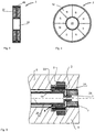
- Fig. 1 shows a schematic longitudinal section through the section or part of the viscometer that is important for the measurement.
- Fig. 2 shows a detailed view of Fig. 1 .
- Figs. 3 and 4 show views of a ring traveler.
- Fig. 5 shows an alternative embodiment. Control and drive units for the electromagnetic drive as well as detectors and evaluation units for the measurement data are not shown; these structural units and their connection are known to the person skilled in the art.
- the viscometer comprises a base frame 5 in which an advantageously cylindrical receiving or cavity 25 is formed, from which a hollow cylinder 1 is received.
- this hollow cylinder 1 does not necessarily have to have a cylindrical outer shape; the outer surfaces or the generators can also run inclined, so that other geometric bodies, in particular rotationally symmetrical to the longitudinal axis of the hollow cylinder 1, can be used.
- the hollow cylinder 1 is mounted in bearings 7 in a fluid-tight manner in both of its end regions.
- pipe stubs 45 are connected to the end regions or end faces of the hollow cylinder 1 or are formed in one piece, with which the hollow cylinder 1 is supported in the bearings 7.
- These pipe sockets 45 enable measurement fluid to flow through the hollow cylinder 1, for example in the direction of arrow 42.
- a measuring part 8 which is advantageously likewise rotationally symmetrical, in particular cylindrical, in shape.
- This measuring part 8 could in principle also have the shape of a polygon in cross section.
- the hollow cylinder 1 is rotated in the interior 25 of the base frame 5.
- the measuring fluid located in the hollow cylinder 1 rotates along with the measuring fluid flowing through the hollow cylinder 1.
- the measuring part 8 swims in the fluid and rotates due to a braking effect as a result of the interaction of a permanent magnet 41 located in the measuring part 8 with an electrically conductive eddy current body 40 or soft iron ring rigidly connected to the base frame 5, essentially at a lower speed than the hollow cylinder 1.
- the speed difference between Hollow cylinder 1 and measuring part 8 can be used and evaluated as a measure of the viscosity of the liquid.
- the measuring part 8 in the interior of the hollow cylinder 1 can be stabilized with regard to its position in the longitudinal and / or transverse direction. For example, interacting magnets or a combination of a soft iron ring 40 on the base frame 5 and the magnet 41 on the measuring part 8 can be provided.
- the speed of the measuring part 8 can be determined, for example, by means of a Hall sensor 47 and the magnet 41.
- a Hall sensor 47 For the rotational drive of the hollow cylinder 1, at least one coil or at least one winding or at least one electromagnet are arranged in the base frame 5 as the stator 2 of the electromagnetic drive used for the hollow cylinder 8.
- the hollow cylinder 1 is not driven directly, however, but via a ring traveler 3 which is mounted on the base frame 5 with a bearing 20 and which is located in front of the stator 2.
- the ring traveler 3 is mounted on the base frame 5 or on an axis of rotation carried by the base frame 5 and carries permanent magnets, electromagnets or windings which interact with the respective permanent magnets, electromagnets or windings on the base frame 5, i.e. the stator 2.
- the ring traveler 3 rotates around the longitudinal axis of the hollow cylinder 1, driven by the stator 2, and induces eddy currents in an annular flange 4 carried by the hollow cylinder 1, which cause a rotation of the annular flange 4 and the hollow cylinder 1.
- the base frame 5 or the stator 2 on the one hand and the hollow cylinder 1 on the other hand are thus mechanically decoupled with regard to the electromagnetic drive. Nevertheless, a predetermined torque can be transmitted to the hollow cylinder 1, with however, at the same time the undesired axial and radial forces acting on the hollow cylinder 1 are minimized.
- the ring flange 4 forming the rotor 14 is made of electrically conductive, but non-magnetic and non-magnetizable material and can be driven by the ring traveler 3 due to the eddy currents induced by the ring traveler 3 in the ring flange 4.
- stator 2 In order to minimize the forces acting on the hollow cylinder 1, it is provided that the stator 2, the ring traveler 3 and the rotor 14 designed as an annular flange 4 are arranged on the base frame 5 one after the other in the axial direction of the hollow cylinder 1.
- stator 2 and the ring traveler 3 and the bearing 20 carrying the ring traveler 3 are encapsulated in a fluid-tight manner, in particular with a fluid-tight membrane 31, in relation to the interior space 25 of the base frame 5 receiving the hollow cylinder 1.
- test fluid it is possible for the test fluid to come into contact with the stator 2, the interior 25 of the base frame 5 and the ring traveler 3 if test fluid escapes from the hollow cylinder 1 or if the bearings 7 for the pipe sockets 45 of the hollow cylinder 1 leak avoid.
- the left and right sections 5 'of the base frame 5 can be separated from the base frame 5 or the bearing 7 located there can be removed from the connecting piece or pipe socket 45 of the hollow cylinder 1, so that access to the hollow cylinder 1 or an exchange of the bearing 7 is possible.
- FIGs. 3 and 4 show a front view or a sectional view of an embodiment of the ring traveler 3.
- a ring-shaped carrier 46 is mounted on a bearing 20 and carries permanent magnets 32 on both sides, which are arranged with alternating polarity around the circumference of the carrier 46.
- Such a ring traveler 3 is rotated by the stator 2 located on the base frame 5 and in turn rotates the ring flange 14 carried by the hollow cylinder 1.
- Fig. 5 shows an alternative embodiment in which the ring traveler 3 carried by the bearing 20 lies radially inside or in front of the stator (s) 2.
- the rotor 14 is formed by a hollow cylinder or ring component which is carried by the hollow cylinder 1 and surrounds it and is arranged radially inside the ring traveler 3.
Landscapes
- Analytical Chemistry (AREA)
- Immunology (AREA)
- Physics & Mathematics (AREA)
- Health & Medical Sciences (AREA)
- Life Sciences & Earth Sciences (AREA)
- Chemical & Material Sciences (AREA)
- General Health & Medical Sciences (AREA)
- Biochemistry (AREA)
- Pathology (AREA)
- General Physics & Mathematics (AREA)
- Engineering & Computer Science (AREA)
- Power Engineering (AREA)
- Connection Of Motors, Electrical Generators, Mechanical Devices, And The Like (AREA)
- Motor Or Generator Frames (AREA)
Description
- Es existieren Messsysteme zur Messung von Flüssigkeitseigenschaften, insbesondere der Viskosität, deren zentraler Bestandteil ein mit der zu messenden Flüssigkeit gefüllter, um seine Längsachse rotierender Hohlzylinder ist, in dem ein Messteil drehbar gelagert ist, der bei Rotation des äußeren Messteils bzw. Hohlzylinders über das zu prüfende fluide Medium mitrotiert wird. Dieser Aufbau entspricht im Wesentlichen einem Viskosimeter nach dem Couette-Prinzip, bei dem aus dem sich einstellenden Gleichgewicht zwischen dem mit konstanter Geschwindigkeit rotierten, außen liegenden Hohlzylinder und dem mitbewegten, inneren Messteil auf die Viskosität des Fluids zwischen den konzentrischen Messteilen, bevorzugt Zylinder, geschlossen wird.
- Im Folgenden wird immer auf einen Hohlzylinder Bezug genommen, obwohl die Form der Innenfläche dieses außenliegenden Messteils nicht unbedingt zylindrisch sein muss. Gleiches gilt für die Außenfläche des innenliegenden Messteils. Zum Beispiel könnten die beiden Messteile jeweils die Form von zwei mit ihren Kreisflächen aneinander anliegenden Kegelstümpfen besitzen. Der Innenraum des außen liegenden Messteils und die Außenfläche des innen liegenden Messteils sollen zumindest axialsymmetrisch sein bzw. Rotationskörper bezüglich der Längsachse des Hohlzylinders darstellen.
- Viskosimeter nach dem Couette-Prinzip sind mit einer Vielzahl von Mess- und Auswertungseinrichtungen bekannt. Beispielsweise kann der sich einstellende Winkel bzw. Nachlaufwinkel zwischen dem rotierenden äußeren und dem mitrotierten inneren Messteil gemessen werden - dabei rotieren beide Messteile mit der gleichen Geschwindigkeit - und daraus die Viskosität der Flüssigkeit ermittelt werden. Eine weitere Methode ist die Messung des auf den innenliegenden Messteil wirkenden Drehmoments, wobei der innenliegende Messteil in Ruhe verbleibt bzw. festgehalten wird. Allgemein werden die ermittelten Daten mit einem Sensor erfasst und an eine Steuer- und Auswerteeinheit übermittelt.
- Eine weitere Variante der Messung wird durch Aufbringung eines Bremsmomentes auf den inneren Messteil bzw. Zylinder möglich und aus dem sich einstellenden Drehzahlunterschied der beiden Zylinder bzw. Messteile kann auf die Viskosität des Mediums zwischen den Zylindern geschlossen werden. Derartige Anordnungen werden insbesondere mit horizontaler Drehachse eingesetzt (
AT 406425 B8 AT 503994 A1 AT 507220 B1 - Um einen Hohlzylinder aus verschiedenen Gründen ― Probemenge, Reinigung, Thermostatisierung, etc. ― möglichst klein gestalten zu können und in der geschlossenen Zelle oder im Durchfluss messen zu können, ist es von Vorteil, wenn der Hohlzylinder entlang seiner Längs- bzw. Rotationsachse so befüllbar ist, dass die Probeflüssigkeit auf einer Seite in den Hohlzylinder eintritt und auf der gegenüberliegenden Seite austritt. Um ein von Luftblasen freies Nachfüllen der zu messenden Probe ohne zwischenzeitige Reinigung zu ermöglichen, ist es von Vorteil, wenn der Hohlzylinder während der Rotation nicht verschlossen bzw. durchströmt ist. Dies stellt eine Herausforderung an die Dichtung, Lagerung und den Antrieb des Hohlzylinders dar.
- Für die Dichtung und Lagerung eines rotierenden Hohlzylinders bietet der Stand der Technik unterschiedliche Möglichkeiten. Sie alle haben den Nachteil, dass eine vollständige Dichtung auf Dauer nicht gewährleistet werden kann. Daher ist es ein Ziel der Erfindung, die Anzahl der zu dichtenden, rotierenden Elemente möglichst klein zu halten.
- Die Rotation des Hohlzylinders erfolgt im Allgemeinen mit Hilfe eines Elektromotors, wobei es für die Übertragung der Rotation des Elektromotors auf den Hohlzylinder verschiedene Möglichkeiten gibt.
- Möglich ist ein konzentrischer Antrieb. Dabei haben der Hohlzylinder und der Motor eine gemeinsame Rotationsachse. Der Antrieb des Hohlzylinders kann über eine Welle erfolgen. Das hat den Nachteil, dass ein weiteres Dichtelement für die Welle notwendig ist, was zu einer weiteren potentiellen Undichtheitsstelle führt und eine weitere Stelle mit Verschleißteilen verursacht.
- Eine weitere Möglichkeit für einen Antrieb ist eine magnetische Kopplung. Die Erfahrung zeigt, dass dies aufgrund der nicht konstanten Reibung an den Lagern des Hohlzylinders zu Rotationspendelbewegungen führt, wodurch eine hinreichend gleichförmige Rotation des Hohlzylinders nicht möglich ist. Außerdem sind die radialen und axialen Kräfte nachteilig für die Lagerung und exakte Messungen.
- Exzentrische Antriebe können auf unterschiedliche Weise ausgeführt werden, wie z.B. über Zahnräder, Riemen, usw. Nachteilig daran ist neben den Querkräften, die bei kleinen Ausführungen des Systems für die Lagerung sehr ungünstig sind, dass bei einer eventuellen Undichtheit der rotierenden Dichtung des Hohlzylinders die gegebenenfalls problematische Probenflüssigkeit in Bereiche vordringt, wo sie eine Gefahr darstellen bzw. Schäden verursachen kann. Derartige Anordnungen besitzen den Nachteil, dass zusätzliche Dichtungen und/oder Lagerungen nötig sind.
- Aus der
JP 2008020465 A - Dokumente
EP0926481 A2 undUS4375047 A entsprechen relevanten Stand der Technik auf. - Ziel der Erfindung ist vor allem die Erstellung eines Viskosimeters mit einem Antrieb für einen mit Probenflüssigkeit gefüllten Hohlzylinder, welcher Antrieb keine aufwendige Dichtung benötigt, außerdem eine Kapselung des Hohlzylinders erlaubt und selbst bei Undichtheit der Dichtungen ein Austreten der Probenflüssigkeit in Bereiche verhindert, in welche die Probenflüssigkeit nicht gelangen darf. Allenfalls soll eine Thermostatisierung der Probenflüssigkeit zumindest im rotierenden Bereich einfach möglich sein. Auch eine Thermostatisierung des nichtrotierenden Bereichs soll möglich sein.
- Diese Ziele werden bei einem Viskosimeter der eingangs genannten Art mit den im Kennzeichen des Patentanspruchs 1 angeführten Merkmalen erreicht. Erfindungsgemäß ist somit vorgesehen, dass zur elektromagnetischen Kopplung des Stators mit dem Rotor zwischen dem Stator und dem Rotor ein vom Stator angetriebener Ringläufer um die Längsachse des Hohlzylinders rotierbar gelagert ist, sodass das Grundgestell und der Hohlzylinder im Hinblick auf den elektromagnetischen Antrieb mechanisch entkoppelt sind und das vorgegebene Drehmoment durch den elektromagnetischen Antrieb auf den Hohlzylinder übertragbar ist und gleichzeitig die axial und radial auf den Hohlzylinder einwirkende Kräfte minimiert sind.
- Der Antrieb des erfindungsgemäßen Viskosimeters umfasst somit einen Elektromotor, dessen Stator fest mit dem nicht rotierenden Teil des Messsystems bzw. dem Grundgestell verbunden ist, wogegen der Rotor fest mit dem rotierenden Hohlzylinder verbunden ist. Dabei sind alle Typen von Statoren von Elektromotoren (Gleichstrom-, Synchron-, Asynchron-, Schrittmotor) möglich, die für eine kontinuierliche Rotation eines Rotors bzw. im vorliegenden Fall für den Antrieb des Ringläufers geeignet sind.
- Erfindungsgemäß wird verhindert, dass störende Kräfte auf den Hohlzylinder wirken, die die Messung verfälschen. Auch ist der Stator thermisch vom Hohlzylinder getrennt und die Temperierung des Messfluids wird im Regelfall mit einem den Rotor umgebenden Temperierblock erfolgen.
- Die Nachteile von bekannten Anordnungen, nämlich zumindest eine zusätzliche Dichtung, die nötig ist, um den Antrieb fluiddicht zu gestalten, werden vermieden.
- Aufgrund der thermischen Empfindlichkeit derartiger Messungen und der mechanischen Empfindlichkeit des Messsystems auf Querkräfte, die durch den Antrieb auf den Rotor in das System eingebracht werden können, ist der Einsatz von herkömmlichen Hohlwellenmotoren bzw. von Steppermotoren nicht möglich. Erfindungsgemäß wird jedoch eine mechanische und auch thermische Entkopplung ermöglicht.
- Die Erfindung löst somit das Problem, einen speziellen Antrieb für einen vom Grundgestell thermisch und mechanisch entkoppelten Hohlzylinder in einem Viskosimeter mit bevorzugt horizontaler Ausrichtung der Drehachse des Hohlzylinders zu erstellen, da ein direkt am Hohlzylinder sitzender Hohlwellenmotor im Betrieb Wärme produziert und damit die empfindliche und hochgenaue Temperierung des Systems stören würde.
- Der wesentliche Nachteil aller bekannten Ausführungsformen wird behoben, nämlich die zwar geringen, aber für eine weitere Miniaturisierung störenden Kräfte in axialer und radialer Richtung. Um diese Kräfte auf die Lagerung des Rotors zu minimieren, ist die Wirbelstromkopplung zwischen dem Ringläufer des elektromagnetischen Antriebs und dem rotierenden Hohlzylinder vorgesehen. Zweckmäßig trägt der Ringläufer des elektromagnetischen Antriebs Permanentmagnete, die den auf dem zu rotierenden Hohlzylinder befindlichen Wirbelstromkörper bzw. Ringflansch antreiben, während der Ringläufer selbst am feststehenden Teil bzw. Grundgestell des Viskosimeters vom Stator rotierbar gelagert ist. Ein weiterer Vorteil dieser Wirbelstromkopplung ist, dass diese dämpfend wirkt und damit störende Drehzahlschwankungen des Elektromotors sich nicht nachteilig auf die Drehzahlstabilität des zu rotierenden Hohlzylinders auswirken. Ein Vorteil von rotierenden Magneten gegenüber einem durch Spulen erzeugten Drehfeld ist, dass für die nötige Magnetfeldstärke die Spulen groß dimensioniert werden müssten und aufgrund der großen, nötigen Leistung beträchtliche Abwärme entstehen würde. Somit sind Permanentmagnete Spulen vorzuziehen.
- Um den Stator bzw. die Permanentmagnete und das Lager des Ringläufers vor eventuell aggressiven Proben- oder Reinigungsflüssigkeiten zu schützen, kann eine Membran oder Membranscheibe bzw. fluiddichte Isolierschicht zwischen dem Stator und dem rotierenden System aus Permanentmagneten inklusive Lager einerseits und dem rotierenden Hohlzylinder, der den Wirbelstromkörper trägt, andererseits, vorgesehen sein. Erfindungsgemäß wird ein dreiteiliger Motor erstellt, der aus einer Spulenanordnung eines Stators besteht, die einen gelagerten, umlaufenden Permanentmagneten tragenden Ringläufer antreibt, der seinerseits einen Wirbelstromantrieb des Messbechers bzw. Hohlzylinders realisiert.
- Betrachtet man bekannte Hohlmotoren mit Stator plus Spulen und Rotor ― beispielsweise mit Magneten ― so kommt es beim Antrieb zu Slip-Stick-Effekten; es treten sowohl axial als auch radial unerwünscht Kräfte auf. Beide Effekte können die Fluidlager derart, beispielsweise axial, belasten, dass die Lager undicht werden. Durch die radiale Belastung der Lagerung des Hohlzylinders kann die Welle sogar aus der Lagerung springen. Bei der Erfindung werden derartige Belastungen vermieden.
- Der erfindungsgemäße Antrieb ermöglicht somit eine weitgehende Miniaturisierung.
- Im Folgenden wird ein erfindungsgemäßes Viskosimeter anhand der Zeichnungen beispielsweise näher erläutert.
-
Fig. 1 zeigt einen schematischen Längsschnitt durch den für die Messung wichtigen Abschnitt bzw. Teil des Viskosimeters.Fig. 2 zeigt eine Detailansicht vonFig. 1 .Fig. 3 und 4 zeigen Ansichten eines Ringläufers.Fig. 5 zeigt eine alternative Ausführungsform. Steuer- und Antriebseinheiten für den elektromagnetischen Antrieb sowie Detektoren und Auswerteeinheiten für die Messdaten sind nicht dargestellt; diese Baueinheiten und deren Anschluss sind dem Fachmann bekannt. - Wie in
Fig. 1 schematisch dargestellt ist, umfasst das erfindungsgemäße Viskosimeter ein Grundgestell 5, in dem ein vorteilhafterweise zylindrisch ausgebildeter Aufnahme- bzw. Hohlraum 25 ausgebildet ist, von dem ein Hohlzylinder 1 aufgenommen wird. Wie bereits erwähnt, muss dieser Hohlzylinder 1 nicht unbedingt zylindrische Außenform besitzen; die Außenflächen bzw. die Erzeugenden können auch geneigt verlaufen, sodass andere, insbesondere zur Längsachse des Hohlzylinders 1 rotationssymmetrisch ausgebildete, geometrische Körper eingesetzt werden können. - Der Hohlzylinder 1 ist in seinen beiden Endbereichen in Lagern 7 fluiddicht gelagert. Dazu sind an die Endbereiche bzw. Stirnflächen des Hohlzylinders 1 Rohrstutzen 45 angeschlossen oder einstückig angeformt, mit denen der Hohlzylinder 1 in den Lagern 7 gelagert ist. Diese Rohrstutzen 45 ermöglichen ein Durchströmen des Hohlzylinders 1 mit Messfluid, beispielsweise in Richtung des Pfeils 42.
- Im Inneren des Hohlzylinders 1 befindet sich ein vorteilhafterweise ebenfalls rotationssymmetrisch, insbesondere zylindrisch, geformter Messteil 8. Dieser Messteil 8 könnte prinzipiell im Querschnitt auch die Form eines Vielecks besitzen.
- Für die Messung wird der Hohlzylinder 1 im Innenraum 25 des Grundgestells 5 rotiert. Dabei wird über das den Hohlzylinder 1 durchströmende Messfluid der im Hohlzylinder 1 befindliche Messteil 8 mitrotiert. Der Messteil 8 schwimmt im Fluid und rotiert aufgrund einer Bremswirkung infolge der Wechselwirkung eines im Messteil 8 befindlichen Permanentmagneten 41 mit einem elektrisch leitfähigen mit dem Grundgestell 5 starr verbundenen Wirbelstromkörper 40 bzw. Weicheisenring im Wesentlichen mit einer niedrigeren Geschwindigkeit wie der Hohlzylinder 1. Die Drehzahldifferenz zwischen Hohlzylinder 1 und Messteil 8 kann als Maß für die Viskosität der Flüssigkeit herangezogen und ausgewertet werden. Der Messteil 8 im Innenraum des Hohlzylinders 1 kann bezüglich seiner Lage in Längs- und/oder Querrichtung stabilisiert werden, Beispielsweise können-zusammenwirkende Magnete oder eine Kombination aus einem Weicheisenring 40 am Grundgestell 5 und den Magnet 41 am Messteil 8 vorgesehen sein.
- Diese Anordnungen legen den Hohlzylinder 8 vor allem bezüglich seiner axialen Lage bzw. in Längsrichtung des Hohlzylinders 1 fest. Die Drehzahl des Messteils 8 kann beispielsweise mittels eines Hallsensors 47 und des Magneten 41 bestimmt werden. Zum Rotationsantrieb des Hohlzylinders 1 sind im Grundgestell 5 als Stator 2 des eingesetzten elektromagnetischen Antriebs für den Hohlzylinder 8 zumindest eine Spule oder zumindest eine Wicklung oder zumindest ein Elektromagnet angeordnet. Der Antrieb des Hohlzylinders 1 erfolgt jedoch nicht direkt, sondern über einen am Grundgestell 5 mit einem Lager 20 gelagerten Ringläufer 3, der vor dem Stator 2 liegt. Der Ringläufer 3 ist auf dem Grundgestell 5 oder auf einer vom Grundgestell 5 getragenen Drehachse gelagert und trägt Permanentmagnete, Elektromagnete oder Wicklungen, die mit den jeweiligen Permanentmagneten, Elektromagneten oder Wicklungen am Grundgestell 5, d.h. dem Stator 2, zusammenwirken. Der Ringläufer 3 rotiert angetrieben vom Stator 2 um die Längsachse des Hohlzylinders 1 und induziert in einem vom Hohlzylinder 1 getragenen Ringflansch 4 Wirbelströme, die eine Rotation des Ringflansches 4 und des Hohlzylinders 1 bewirken.
- Das Grundgestell 5 bzw. der Stator 2 einerseits und der Hohlzylinder 1 andererseits sind somit im Hinblick auf den elektromagnetischen Antrieb mechanisch entkoppelt. Trotzdem kann ein vorgegebenes Drehmoment auf den Hohlzylinder 1 übertragen werden, wobei jedoch gleichzeitig die auf den Hohlzylinder 1 einwirkenden, unerwünschten axialen und radialen Kräfte minimiert sind. Der den Rotor 14 ausbildende Ringflansch 4 ist aus elektrisch leitendem, jedoch nicht magnetischem und nicht magnetisierbarem Material gebildet und vom Ringläufer 3 aufgrund der vom Ringläufer 3 im Ringflansch 4 induzierten Wirbelströme antreibbar.
- Für eine Minimierung der auf den Hohlzylinder 1 einwirkenden Kräfte ist vorgesehen, dass der Stator 2, der Ringläufer 3 und der als Ringflansch 4 ausgebildete Rotor 14 am Grundgestell 5 in axialer Richtung des Hohlzylinders 1 aufeinanderfolgend, nebeneinander liegend angeordnet sind.
- Ferner ist es zweckmäßig, wenn ― wie in
Fig. 1 und 2 dargestellt ― der Stator 2 und der Ringläufer 3 und das den Ringläufer 3 tragende Lager 20 gegenüber dem den Hohlzylinder 1 aufnehmenden Innenraum 25 des Grundgestells 5 fluiddicht, insbesondere mit einer fluiddichten Membran 31, eingekapselt sind. Auf diese Weise ist es möglich, bei einem Austritt von Prüffluid aus dem Hohlzylinder 1 oder bei einem Undichtwerden der Lager 7 für die Rohrstutzen 45 des Hohlzylinders 1 einen Kontakt des Prüffluids mit dem Stator 2 , dem Innenraum 25 des Grundgestells 5 und dem Ringläufer 3 zu vermeiden. - Wie aus
Fig. 1 und 2 ersichtlich, sind der linke und der rechte Abschnitt 5' des Grundgestells 5 vom Grundgestell 5 trennbar bzw. ist das dort befindliche Lager 7 von dem Anschlussstutzen bzw. Rohrstutzen 45 des Hohlzylinders 1 abziehbar, sodass ein Zutritt zum Hohlzylinder 1 bzw. ein Austausch des Lagers 7 möglich ist. -
Fig. 3 und 4 zeigen eine Vordersicht bzw. eine Schnittansicht einer Ausführungsform des Ringläufers 3. Auf einem Lager 20 ist ein ringförmiger Träger 46 gelagert, der beidseits Permanentmagnete 32 trägt, die mit abwechselnder Polung um den Umfang des Trägers 46 auf diesem angeordnet sind. Ein derartiger Ringläufer 3 wird von dem am Grundgestell 5 befindlichen Stator 2 rotiert und rotiert seinerseits wiederum den vom Hohlzylinder 1 getragenen Ringflansch 14. -
Fig. 5 zeigt eine alternative Ausführungsform, bei der der vom Lager 20 getragene Ringläufer 3 radial innerhalb des bzw. vor dem Stator(s) 2 liegt. Der Rotor 14 ist von einem Hohlzylinder oder Ringbauteil gebildet, der vom Hohlzylinder 1 getragen ist und diesen umgibt und radial innerhalb des Ringläufers 3 angeordnet ist.
Claims (14)
- Viskosimeter mit einem in einem Grundgestell (5) um seine Längsachse rotierbar gelagerten Hohlzylinder (1), in dem ein, insbesondere zylindrischer, vom zu prüfenden Fluid durchströmbarer Messteil (8) rotierbar gelagert ist, dadurch gekennzeichnet,- dass ein elektromagnetischer Antrieb mit einem Stator (2) und einem Rotor (14) für den Hohlzylinder (1) vorgesehen ist, mit dem der Hohlzylinder (1) im Grundgestell (5) rotierbar ist, wobei der Stator (2) des Antriebs am Grundgestell (5) und der Rotor (14) des Antriebs vom Hohlzylinder (1) getragen ist, und- dass zur elektromagnetischen Kopplung des Stators (2) mit dem Rotor (14) zwischen dem Stator (2) und dem Rotor (14) ein vom Stator angetriebener Ringläufer (3) um die Längsachse des Hohlzylinders (1) rotierbar gelagert ist, sodass das Grundgestell (5) und der Hohlzylinder (1) im Hinblick auf den elektromagnetischen Antrieb mechanisch entkoppelt sind und das vorgegebene Drehmoment durch den elektromagnetischen Antrieb auf den Hohlzylinder (1) übertragbar ist und gleichzeitig die axial und radial auf den Hohlzylinder (1) einwirkende Kräfte minimiert sind.
- Viskosimeter nach Anspruch 1, dadurch gekennzeichnet, dass der Hohlzylinder (5) an seinen gegenüberliegenden Endbereichen mit Dichtlagern (7) im Grundgestell (5) fluiddicht rotierbar gelagert ist.
- Viskosimeter nach Anspruch 1 oder 2, dadurch gekennzeichnet, dass der Hohlzylinder (1) insbesondere im Bereich seiner Rotations- bzw. Längsachse an seinen beiden Enden jeweils mit einer Durchströmöffnung (24) oder mit einem Anschlussrohrstutzen (45) versehen ist.
- Viskosimeter nach einem der Ansprüche 1 bis 3, dadurch gekennzeichnet,- dass als Stator (2) des elektromagnetischen Antriebs zumindest eine elektromagnetische Spule oder Wicklung oder zumindest ein Elektromagnet am Grundgestell (5), insbesondere um den Hohlzylinder (1) herum, angeordnet ist, und- dass der Ringläufer (3) Permanentmagnete oder Elektromagnete oder eine Anzahl von Wicklungen aufweist, wobei vorteilhafterweise nebeneinander liegende Permanentmagnete oder Elektromagnete oder Wicklungen an einem Tragring (46) des Ringläufers (3) mit zueinander entgegengesetzter Polung angeordnet sind.
- Viskosimeter nach einem der Ansprüche 1 bis 4, dadurch gekennzeichnet,- dass der Ringläufer (3) auf dem Grundgestell (5) oder einer vom Grundgestell (5) getragenen Drehachse gelagert ist, und/oder- dass die am Ringläufer (3) befindlichen Permanentmagnete, Elektromagnete oder Wicklungen den Spulen bzw. Wicklungen oder Elektromagneten des Stators (2), in axialer oder radialer Richtung des Hohlzylinders (1) gesehen, gegenüberliegend angeordnet sind.
- Viskosimeter nach einem der Ansprüche 1 bis 5, dadurch gekennzeichnet, dass der Rotor (14) ein, vorzugsweise in einem Endbereich des Hohlzylinders (1), direkt vom Hohlzylinder (1) abgehender bzw. getragener Ringflansch (4) oder ein, vorzugsweise in einem Endbereich des Hohlzylinders, von vom Hohlzylinder (1) abgehenden Trägern getragener Ringflansch (4) ist.
- Viskosimeter nach einem der Ansprüche 1 bis 6, dadurch gekennzeichnet, dass der Ringflansch (4) von der Außenwand des Hohlzylinders (1) radial abgeht und sich gegebenenfalls unterbrechungsfrei um den Hohlzylinder (1) herum erstreckt.
- Viskosimeter nach einem der Ansprüche 1 bis 7, dadurch gekennzeichnet, dass der Ringläufer (3) auf einem vom Grundgestell (5) getragenen, insbesondere den Hohlzylinder (1) umgebenden, Lager (20) um den Hohlzylinder (1) rotierbar ist.
- Viskosimeter nach einem der Ansprüche 1 bis 8, dadurch gekennzeichnet, dass der Rotor (14) von einem mit dem Hohlzylinder (1) verbundenen und diesen umgebenden Hohlzylinder oder Ringbauteil (4') gebildet ist, wobei der Ringläufer (3) radial innerhalb des Stators (2) und radial außerhalb des Rotors (14) angeordnet ist bzw. umläuft.
- Viskosimeter nach einem der Ansprüche 1 bis 9, dadurch gekennzeichnet, dass der den Rotor (14) ausbildende Ringflansch (4) oder Ringbauteil (4') aus elektrisch leitendem, vorzugsweise jedoch nicht magnetischem und nicht magnetisierbarem, Material, insbesondere Metall, besteht und vom Ringläufer (3) aufgrund der vom Ringläufer (3) im Ringflansch (4) induzierten Wirbelströme antreibbar ist.
- Viskosimeter nach einem der Ansprüche 1 bis 10, dadurch gekennzeichnet, dass der vom Hohlzylinder (1) getragene Rotor (14) ausschließlich durch die vom Ringläufer (3) im Ringflansch (4) oder Ringbauteil (4') des Rotors (14) induzierten Wirbelströme angetrieben ist.
- Viskosimeter nach einem der Ansprüche 1 bis 11, dadurch gekennzeichnet, dass der Stator (2), der Ringläufer (3) und der als Ringflansch (4) ausgebildete Rotor (14) am Grundgestell (5) in axialer oder radialer Richtung des Hohlzylinders (1) aufeinanderfolgend bzw. nebeneinander liegend angeordnet sind.
- Viskosimeter nach einem der Ansprüche 1 bis 12, dadurch gekennzeichnet, dass der Stator (2) und der Ringläufer (3) und das den Ringläufer (3) tragende Lager (20) gegenüber dem den Hohlzylinder (1) aufnehmenden Innenraum (25) des Grundgestells (5) fluiddicht, insbesondere mit einer fluiddichten Membran (31), abgedeckt bzw. eingekapselt sind.
- Viskosimeter nach einem der Ansprüche 1 bis 13, dadurch gekennzeichnet, dass die Längsachse des Hohlzylinders (1) und die Rotationsachse des Ringläufers (3) zusammenfallen.
Applications Claiming Priority (1)
| Application Number | Priority Date | Filing Date | Title |
|---|---|---|---|
| ATA50635/2014A AT516058B1 (de) | 2014-09-12 | 2014-09-12 | Viskosimeter |
Publications (2)
| Publication Number | Publication Date |
|---|---|
| EP2995928A1 EP2995928A1 (de) | 2016-03-16 |
| EP2995928B1 true EP2995928B1 (de) | 2021-11-24 |
Family
ID=54065283
Family Applications (1)
| Application Number | Title | Priority Date | Filing Date |
|---|---|---|---|
| EP15184091.5A Active EP2995928B1 (de) | 2014-09-12 | 2015-09-07 | Viskosimeter |
Country Status (4)
| Country | Link |
|---|---|
| US (1) | US10036695B2 (de) |
| EP (1) | EP2995928B1 (de) |
| CN (1) | CN105424556B (de) |
| AT (1) | AT516058B1 (de) |
Families Citing this family (7)
| Publication number | Priority date | Publication date | Assignee | Title |
|---|---|---|---|---|
| US10833555B2 (en) * | 2015-11-27 | 2020-11-10 | Foundation Of Soongsil University Industry Cooperation | Motor for reducing a repulsive force |
| CN106290070B (zh) * | 2016-09-30 | 2017-11-03 | 北京金风科创风电设备有限公司 | 应用液体粘接剂混合物粘度实时测量装置的试验装置 |
| AT518658B1 (de) | 2017-01-12 | 2017-12-15 | Wolfgang Belitsch Dr | Viskosimeter zur Bestimmung der dynamischen und der kinematischen Viskosität |
| RU177848U1 (ru) * | 2017-10-05 | 2018-03-14 | Акционерное общество "ГМС Нефтемаш" | Поточный вискозиметр |
| NL2022209B1 (en) * | 2018-12-14 | 2020-07-03 | Vmi Holland Bv | Measuring device and method for determining rheological properties of a viscous, polymeric mass |
| AT522151B1 (de) * | 2018-12-21 | 2020-09-15 | Anton Paar Gmbh | Verfahren zur Reinigung eines Viskosimeters |
| AT525776B1 (de) | 2021-12-23 | 2023-09-15 | Anton Paar Gmbh | Verfahren zur Befüllung und/oder Reinigung der Messzelle eines Rotationsviskosimeters |
Citations (1)
| Publication number | Priority date | Publication date | Assignee | Title |
|---|---|---|---|---|
| EP0926481B1 (de) * | 1997-12-18 | 2004-05-06 | Hans Dr. Stabinger | Vorrichtung zur Bestimmung der Viskosität einer Flüssigkeit |
Family Cites Families (17)
| Publication number | Priority date | Publication date | Assignee | Title |
|---|---|---|---|---|
| AT40425B (de) | 1906-07-13 | 1910-01-10 | Leopold Bauer | Bandwebstuhl zur Herstellung von Bändern mit Einlage. |
| GB1244408A (en) * | 1969-03-05 | 1971-09-02 | Rosemount Eng Co Ltd | Improvements in or relating to viscometers |
| DE2632076C3 (de) * | 1976-07-16 | 1981-08-13 | Heinz, Werner, Dipl.-Phys., 5000 Köln | Betriebsviskosimeter |
| US4375047A (en) * | 1981-07-23 | 1983-02-22 | General Signal Corporation | Torque compensated electrical motor |
| DD252438A1 (de) * | 1986-08-08 | 1987-12-16 | Medizin Labortechnik Veb K | Rotationsviskosimeter |
| WO1995009353A1 (en) * | 1993-09-29 | 1995-04-06 | Toki Sangyo Co., Ltd. | Automatic viscosity measuring apparatus with rotor automatically detachable |
| DE4408816C1 (de) * | 1994-03-16 | 1995-08-03 | Martin Pfeil Trawid Gmbh | Rotationsviskosimeter |
| DE29501957U1 (de) * | 1995-02-07 | 1995-03-23 | Feodor Burgmann Dichtungswerke GmbH & Co, 82515 Wolfratshausen | Viskosimeter |
| CN1051614C (zh) * | 1996-07-30 | 2000-04-19 | 李钢 | 旋转剪切速率降速式粘度测量法及其装置 |
| US6640617B2 (en) * | 2001-08-16 | 2003-11-04 | Levitronix Llc | Apparatus and a method for determining the viscosity of a fluid |
| CN1667394A (zh) * | 2004-03-11 | 2005-09-14 | 北京中矿机电工程技术研究所 | 加压旋转流变仪 |
| GB0419152D0 (en) * | 2004-08-27 | 2004-09-29 | Kernow Instr Technology Ltd | A contactless magnetic rotary bearing and a rheometer incorporating such bearing |
| CN2802498Y (zh) * | 2005-07-11 | 2006-08-02 | 中国矿业大学 | 一种磁性液体表观粘度测试仪 |
| AT503994B1 (de) | 2006-08-03 | 2008-05-15 | Messtechnik Dr H Stabinger Gmb | Vorrichtung und verfahren zum bestimmen der viskosität einer flüssigkeit |
| JP4389059B2 (ja) | 2007-09-14 | 2009-12-24 | 独立行政法人産業技術総合研究所 | 直接駆動モータを用いた回転粘度計 |
| AT507220B1 (de) | 2009-02-27 | 2010-03-15 | Messtechnik Dr Hans Stabinger | Viskosimeter |
| CN102023124B (zh) * | 2010-10-15 | 2012-05-16 | 哈尔滨工业大学 | 基于速度衰减的旋转粘度计 |
-
2014
- 2014-09-12 AT ATA50635/2014A patent/AT516058B1/de active
-
2015
- 2015-09-07 EP EP15184091.5A patent/EP2995928B1/de active Active
- 2015-09-11 CN CN201510577870.XA patent/CN105424556B/zh active Active
- 2015-09-14 US US14/852,799 patent/US10036695B2/en active Active
Patent Citations (1)
| Publication number | Priority date | Publication date | Assignee | Title |
|---|---|---|---|---|
| EP0926481B1 (de) * | 1997-12-18 | 2004-05-06 | Hans Dr. Stabinger | Vorrichtung zur Bestimmung der Viskosität einer Flüssigkeit |
Also Published As
| Publication number | Publication date |
|---|---|
| AT516058A4 (de) | 2016-02-15 |
| AT516058B1 (de) | 2016-02-15 |
| CN105424556A (zh) | 2016-03-23 |
| EP2995928A1 (de) | 2016-03-16 |
| CN105424556B (zh) | 2019-09-24 |
| US20160076986A1 (en) | 2016-03-17 |
| US10036695B2 (en) | 2018-07-31 |
Similar Documents
| Publication | Publication Date | Title |
|---|---|---|
| EP2995928B1 (de) | Viskosimeter | |
| EP1284415B1 (de) | Vorrichtung und Verfahren zur Bestimmung der Viskosität eines Fluids | |
| US8132445B2 (en) | Rheometer | |
| DE112007001851B4 (de) | Dauerlast-Scherzelle für magnetorheologische Flüssigkeiten | |
| EP0019313B1 (de) | Magnetisches Schwebelager für einen Rotor | |
| EP0671008B1 (de) | Vorrichtung zur messung von drehbewegungen | |
| AT514549B1 (de) | Rotationsrheometer | |
| DE102011075548A1 (de) | Lager mit einer Energieerfassungseinheit, insbesondere Pendelrollen-Lager zur Lagerung einer Walze | |
| DE102016121085B3 (de) | Vorrichtung zur Messung physikalischer Größen eines Messmotors und diesbezügliches Messverfahren | |
| WO2007033982A1 (de) | Verfahren und anordnung zur berührungslosen inspektion bewegter elektrisch leitfähiger substanzen | |
| DE4120243A1 (de) | Magnetpulverkupplung | |
| EP0926481B1 (de) | Vorrichtung zur Bestimmung der Viskosität einer Flüssigkeit | |
| DE4104250A1 (de) | Antrieb und lagerung fuer einen oe-spinnrotor | |
| DE10113591C1 (de) | Prüfeinrichtung zur Untersuchung des Verhaltens von Wellendichtsystemen | |
| DD252438A1 (de) | Rotationsviskosimeter | |
| DE1648858C3 (de) | Rotationsviskosimeter | |
| DE102007038635B3 (de) | Anordnung und Verfahren zum elektromagnetischen Dosieren elektrisch leitfähiger Substanzen | |
| EP3714532B1 (de) | Verfahren und anordnung zum bestimmen von mindestens einer eigenschaft einer elektrischen maschine | |
| EP0982836B1 (de) | Verfahren zum Bestimmen der radialen Position eines permanentmagnetischen Rotors und elektromagnetischer Drehantrieb | |
| DE925014C (de) | Viskosimeter | |
| WO2017162243A1 (de) | Antriebseinheit | |
| DE245775C (de) | ||
| DE934899C (de) | Unipolarmaschine fuer hohe Drehzahlen | |
| DE4031269A1 (de) | Wirbelstrombremse | |
| DE2425017C3 (de) | Prüfmaschine für Schmierstoffe |
Legal Events
| Date | Code | Title | Description |
|---|---|---|---|
| PUAI | Public reference made under article 153(3) epc to a published international application that has entered the european phase |
Free format text: ORIGINAL CODE: 0009012 |
|
| AK | Designated contracting states |
Kind code of ref document: A1 Designated state(s): AL AT BE BG CH CY CZ DE DK EE ES FI FR GB GR HR HU IE IS IT LI LT LU LV MC MK MT NL NO PL PT RO RS SE SI SK SM TR |
|
| AX | Request for extension of the european patent |
Extension state: BA ME |
|
| 17P | Request for examination filed |
Effective date: 20160914 |
|
| RBV | Designated contracting states (corrected) |
Designated state(s): AL AT BE BG CH CY CZ DE DK EE ES FI FR GB GR HR HU IE IS IT LI LT LU LV MC MK MT NL NO PL PT RO RS SE SI SK SM TR |
|
| GRAP | Despatch of communication of intention to grant a patent |
Free format text: ORIGINAL CODE: EPIDOSNIGR1 |
|
| STAA | Information on the status of an ep patent application or granted ep patent |
Free format text: STATUS: GRANT OF PATENT IS INTENDED |
|
| RIC1 | Information provided on ipc code assigned before grant |
Ipc: G01N 11/14 20060101AFI20210325BHEP |
|
| INTG | Intention to grant announced |
Effective date: 20210422 |
|
| RIN1 | Information on inventor provided before grant (corrected) |
Inventor name: LEOPOLD, BERNHARD Inventor name: BELITSCH, WOLFGANG |
|
| GRAJ | Information related to disapproval of communication of intention to grant by the applicant or resumption of examination proceedings by the epo deleted |
Free format text: ORIGINAL CODE: EPIDOSDIGR1 |
|
| STAA | Information on the status of an ep patent application or granted ep patent |
Free format text: STATUS: REQUEST FOR EXAMINATION WAS MADE |
|
| GRAP | Despatch of communication of intention to grant a patent |
Free format text: ORIGINAL CODE: EPIDOSNIGR1 |
|
| STAA | Information on the status of an ep patent application or granted ep patent |
Free format text: STATUS: GRANT OF PATENT IS INTENDED |
|
| INTC | Intention to grant announced (deleted) | ||
| INTG | Intention to grant announced |
Effective date: 20210915 |
|
| GRAS | Grant fee paid |
Free format text: ORIGINAL CODE: EPIDOSNIGR3 |
|
| GRAA | (expected) grant |
Free format text: ORIGINAL CODE: 0009210 |
|
| STAA | Information on the status of an ep patent application or granted ep patent |
Free format text: STATUS: THE PATENT HAS BEEN GRANTED |
|
| AK | Designated contracting states |
Kind code of ref document: B1 Designated state(s): AL AT BE BG CH CY CZ DE DK EE ES FI FR GB GR HR HU IE IS IT LI LT LU LV MC MK MT NL NO PL PT RO RS SE SI SK SM TR |
|
| REG | Reference to a national code |
Ref country code: GB Ref legal event code: FG4D Free format text: NOT ENGLISH |
|
| REG | Reference to a national code |
Ref country code: AT Ref legal event code: REF Ref document number: 1450213 Country of ref document: AT Kind code of ref document: T Effective date: 20211215 |
|
| REG | Reference to a national code |
Ref country code: DE Ref legal event code: R096 Ref document number: 502015015424 Country of ref document: DE |
|
| REG | Reference to a national code |
Ref country code: IE Ref legal event code: FG4D Free format text: LANGUAGE OF EP DOCUMENT: GERMAN |
|
| REG | Reference to a national code |
Ref country code: LT Ref legal event code: MG9D |
|
| REG | Reference to a national code |
Ref country code: NL Ref legal event code: MP Effective date: 20211124 |
|
| PG25 | Lapsed in a contracting state [announced via postgrant information from national office to epo] |
Ref country code: RS Free format text: LAPSE BECAUSE OF FAILURE TO SUBMIT A TRANSLATION OF THE DESCRIPTION OR TO PAY THE FEE WITHIN THE PRESCRIBED TIME-LIMIT Effective date: 20211124 Ref country code: LT Free format text: LAPSE BECAUSE OF FAILURE TO SUBMIT A TRANSLATION OF THE DESCRIPTION OR TO PAY THE FEE WITHIN THE PRESCRIBED TIME-LIMIT Effective date: 20211124 Ref country code: FI Free format text: LAPSE BECAUSE OF FAILURE TO SUBMIT A TRANSLATION OF THE DESCRIPTION OR TO PAY THE FEE WITHIN THE PRESCRIBED TIME-LIMIT Effective date: 20211124 Ref country code: BG Free format text: LAPSE BECAUSE OF FAILURE TO SUBMIT A TRANSLATION OF THE DESCRIPTION OR TO PAY THE FEE WITHIN THE PRESCRIBED TIME-LIMIT Effective date: 20220224 |
|
| PG25 | Lapsed in a contracting state [announced via postgrant information from national office to epo] |
Ref country code: IS Free format text: LAPSE BECAUSE OF FAILURE TO SUBMIT A TRANSLATION OF THE DESCRIPTION OR TO PAY THE FEE WITHIN THE PRESCRIBED TIME-LIMIT Effective date: 20220324 Ref country code: SE Free format text: LAPSE BECAUSE OF FAILURE TO SUBMIT A TRANSLATION OF THE DESCRIPTION OR TO PAY THE FEE WITHIN THE PRESCRIBED TIME-LIMIT Effective date: 20211124 Ref country code: PT Free format text: LAPSE BECAUSE OF FAILURE TO SUBMIT A TRANSLATION OF THE DESCRIPTION OR TO PAY THE FEE WITHIN THE PRESCRIBED TIME-LIMIT Effective date: 20220324 Ref country code: PL Free format text: LAPSE BECAUSE OF FAILURE TO SUBMIT A TRANSLATION OF THE DESCRIPTION OR TO PAY THE FEE WITHIN THE PRESCRIBED TIME-LIMIT Effective date: 20211124 Ref country code: NO Free format text: LAPSE BECAUSE OF FAILURE TO SUBMIT A TRANSLATION OF THE DESCRIPTION OR TO PAY THE FEE WITHIN THE PRESCRIBED TIME-LIMIT Effective date: 20220224 Ref country code: NL Free format text: LAPSE BECAUSE OF FAILURE TO SUBMIT A TRANSLATION OF THE DESCRIPTION OR TO PAY THE FEE WITHIN THE PRESCRIBED TIME-LIMIT Effective date: 20211124 Ref country code: LV Free format text: LAPSE BECAUSE OF FAILURE TO SUBMIT A TRANSLATION OF THE DESCRIPTION OR TO PAY THE FEE WITHIN THE PRESCRIBED TIME-LIMIT Effective date: 20211124 Ref country code: HR Free format text: LAPSE BECAUSE OF FAILURE TO SUBMIT A TRANSLATION OF THE DESCRIPTION OR TO PAY THE FEE WITHIN THE PRESCRIBED TIME-LIMIT Effective date: 20211124 Ref country code: GR Free format text: LAPSE BECAUSE OF FAILURE TO SUBMIT A TRANSLATION OF THE DESCRIPTION OR TO PAY THE FEE WITHIN THE PRESCRIBED TIME-LIMIT Effective date: 20220225 Ref country code: ES Free format text: LAPSE BECAUSE OF FAILURE TO SUBMIT A TRANSLATION OF THE DESCRIPTION OR TO PAY THE FEE WITHIN THE PRESCRIBED TIME-LIMIT Effective date: 20211124 |
|
| PG25 | Lapsed in a contracting state [announced via postgrant information from national office to epo] |
Ref country code: SM Free format text: LAPSE BECAUSE OF FAILURE TO SUBMIT A TRANSLATION OF THE DESCRIPTION OR TO PAY THE FEE WITHIN THE PRESCRIBED TIME-LIMIT Effective date: 20211124 Ref country code: SK Free format text: LAPSE BECAUSE OF FAILURE TO SUBMIT A TRANSLATION OF THE DESCRIPTION OR TO PAY THE FEE WITHIN THE PRESCRIBED TIME-LIMIT Effective date: 20211124 Ref country code: RO Free format text: LAPSE BECAUSE OF FAILURE TO SUBMIT A TRANSLATION OF THE DESCRIPTION OR TO PAY THE FEE WITHIN THE PRESCRIBED TIME-LIMIT Effective date: 20211124 Ref country code: EE Free format text: LAPSE BECAUSE OF FAILURE TO SUBMIT A TRANSLATION OF THE DESCRIPTION OR TO PAY THE FEE WITHIN THE PRESCRIBED TIME-LIMIT Effective date: 20211124 Ref country code: DK Free format text: LAPSE BECAUSE OF FAILURE TO SUBMIT A TRANSLATION OF THE DESCRIPTION OR TO PAY THE FEE WITHIN THE PRESCRIBED TIME-LIMIT Effective date: 20211124 Ref country code: CZ Free format text: LAPSE BECAUSE OF FAILURE TO SUBMIT A TRANSLATION OF THE DESCRIPTION OR TO PAY THE FEE WITHIN THE PRESCRIBED TIME-LIMIT Effective date: 20211124 |
|
| REG | Reference to a national code |
Ref country code: DE Ref legal event code: R097 Ref document number: 502015015424 Country of ref document: DE |
|
| PLBE | No opposition filed within time limit |
Free format text: ORIGINAL CODE: 0009261 |
|
| STAA | Information on the status of an ep patent application or granted ep patent |
Free format text: STATUS: NO OPPOSITION FILED WITHIN TIME LIMIT |
|
| PG25 | Lapsed in a contracting state [announced via postgrant information from national office to epo] |
Ref country code: AL Free format text: LAPSE BECAUSE OF FAILURE TO SUBMIT A TRANSLATION OF THE DESCRIPTION OR TO PAY THE FEE WITHIN THE PRESCRIBED TIME-LIMIT Effective date: 20211124 |
|
| 26N | No opposition filed |
Effective date: 20220825 |
|
| PG25 | Lapsed in a contracting state [announced via postgrant information from national office to epo] |
Ref country code: SI Free format text: LAPSE BECAUSE OF FAILURE TO SUBMIT A TRANSLATION OF THE DESCRIPTION OR TO PAY THE FEE WITHIN THE PRESCRIBED TIME-LIMIT Effective date: 20211124 |
|
| PG25 | Lapsed in a contracting state [announced via postgrant information from national office to epo] |
Ref country code: MC Free format text: LAPSE BECAUSE OF FAILURE TO SUBMIT A TRANSLATION OF THE DESCRIPTION OR TO PAY THE FEE WITHIN THE PRESCRIBED TIME-LIMIT Effective date: 20211124 |
|
| REG | Reference to a national code |
Ref country code: BE Ref legal event code: MM Effective date: 20220930 |
|
| PG25 | Lapsed in a contracting state [announced via postgrant information from national office to epo] |
Ref country code: IT Free format text: LAPSE BECAUSE OF FAILURE TO SUBMIT A TRANSLATION OF THE DESCRIPTION OR TO PAY THE FEE WITHIN THE PRESCRIBED TIME-LIMIT Effective date: 20211124 |
|
| PG25 | Lapsed in a contracting state [announced via postgrant information from national office to epo] |
Ref country code: LU Free format text: LAPSE BECAUSE OF NON-PAYMENT OF DUE FEES Effective date: 20220907 |
|
| PG25 | Lapsed in a contracting state [announced via postgrant information from national office to epo] |
Ref country code: IE Free format text: LAPSE BECAUSE OF NON-PAYMENT OF DUE FEES Effective date: 20220907 |
|
| PG25 | Lapsed in a contracting state [announced via postgrant information from national office to epo] |
Ref country code: BE Free format text: LAPSE BECAUSE OF NON-PAYMENT OF DUE FEES Effective date: 20220930 |
|
| REG | Reference to a national code |
Ref country code: AT Ref legal event code: MM01 Ref document number: 1450213 Country of ref document: AT Kind code of ref document: T Effective date: 20220907 |
|
| PG25 | Lapsed in a contracting state [announced via postgrant information from national office to epo] |
Ref country code: AT Free format text: LAPSE BECAUSE OF NON-PAYMENT OF DUE FEES Effective date: 20220907 |
|
| PG25 | Lapsed in a contracting state [announced via postgrant information from national office to epo] |
Ref country code: HU Free format text: LAPSE BECAUSE OF FAILURE TO SUBMIT A TRANSLATION OF THE DESCRIPTION OR TO PAY THE FEE WITHIN THE PRESCRIBED TIME-LIMIT; INVALID AB INITIO Effective date: 20150907 |
|
| PG25 | Lapsed in a contracting state [announced via postgrant information from national office to epo] |
Ref country code: CY Free format text: LAPSE BECAUSE OF FAILURE TO SUBMIT A TRANSLATION OF THE DESCRIPTION OR TO PAY THE FEE WITHIN THE PRESCRIBED TIME-LIMIT Effective date: 20211124 |
|
| PG25 | Lapsed in a contracting state [announced via postgrant information from national office to epo] |
Ref country code: MK Free format text: LAPSE BECAUSE OF FAILURE TO SUBMIT A TRANSLATION OF THE DESCRIPTION OR TO PAY THE FEE WITHIN THE PRESCRIBED TIME-LIMIT Effective date: 20211124 |
|
| PG25 | Lapsed in a contracting state [announced via postgrant information from national office to epo] |
Ref country code: MT Free format text: LAPSE BECAUSE OF FAILURE TO SUBMIT A TRANSLATION OF THE DESCRIPTION OR TO PAY THE FEE WITHIN THE PRESCRIBED TIME-LIMIT Effective date: 20211124 |
|
| PGFP | Annual fee paid to national office [announced via postgrant information from national office to epo] |
Ref country code: CH Payment date: 20241001 Year of fee payment: 10 |
|
| REG | Reference to a national code |
Ref country code: CH Ref legal event code: U11 Free format text: ST27 STATUS EVENT CODE: U-0-0-U10-U11 (AS PROVIDED BY THE NATIONAL OFFICE) Effective date: 20251001 |
|
| PGFP | Annual fee paid to national office [announced via postgrant information from national office to epo] |
Ref country code: DE Payment date: 20250919 Year of fee payment: 11 |
|
| PGFP | Annual fee paid to national office [announced via postgrant information from national office to epo] |
Ref country code: GB Payment date: 20250919 Year of fee payment: 11 |
|
| PGFP | Annual fee paid to national office [announced via postgrant information from national office to epo] |
Ref country code: FR Payment date: 20250922 Year of fee payment: 11 |