EP2995784A1 - Anlagensteuerungsvorrichtung und kombizykluskraftwerk - Google Patents
Anlagensteuerungsvorrichtung und kombizykluskraftwerk Download PDFInfo
- Publication number
- EP2995784A1 EP2995784A1 EP15184211.9A EP15184211A EP2995784A1 EP 2995784 A1 EP2995784 A1 EP 2995784A1 EP 15184211 A EP15184211 A EP 15184211A EP 2995784 A1 EP2995784 A1 EP 2995784A1
- Authority
- EP
- European Patent Office
- Prior art keywords
- valve
- steam
- flow rate
- opening degree
- main steam
- Prior art date
- Legal status (The legal status is an assumption and is not a legal conclusion. Google has not performed a legal analysis and makes no representation as to the accuracy of the status listed.)
- Granted
Links
Images





Classifications
-
- F—MECHANICAL ENGINEERING; LIGHTING; HEATING; WEAPONS; BLASTING
- F01—MACHINES OR ENGINES IN GENERAL; ENGINE PLANTS IN GENERAL; STEAM ENGINES
- F01K—STEAM ENGINE PLANTS; STEAM ACCUMULATORS; ENGINE PLANTS NOT OTHERWISE PROVIDED FOR; ENGINES USING SPECIAL WORKING FLUIDS OR CYCLES
- F01K23/00—Plants characterised by more than one engine delivering power external to the plant, the engines being driven by different fluids
- F01K23/02—Plants characterised by more than one engine delivering power external to the plant, the engines being driven by different fluids the engine cycles being thermally coupled
- F01K23/06—Plants characterised by more than one engine delivering power external to the plant, the engines being driven by different fluids the engine cycles being thermally coupled combustion heat from one cycle heating the fluid in another cycle
- F01K23/10—Plants characterised by more than one engine delivering power external to the plant, the engines being driven by different fluids the engine cycles being thermally coupled combustion heat from one cycle heating the fluid in another cycle with exhaust fluid of one cycle heating the fluid in another cycle
- F01K23/101—Regulating means specially adapted therefor
-
- F—MECHANICAL ENGINEERING; LIGHTING; HEATING; WEAPONS; BLASTING
- F01—MACHINES OR ENGINES IN GENERAL; ENGINE PLANTS IN GENERAL; STEAM ENGINES
- F01K—STEAM ENGINE PLANTS; STEAM ACCUMULATORS; ENGINE PLANTS NOT OTHERWISE PROVIDED FOR; ENGINES USING SPECIAL WORKING FLUIDS OR CYCLES
- F01K11/00—Plants characterised by the engines being structurally combined with boilers or condensers
- F01K11/02—Plants characterised by the engines being structurally combined with boilers or condensers the engines being turbines
-
- F—MECHANICAL ENGINEERING; LIGHTING; HEATING; WEAPONS; BLASTING
- F01—MACHINES OR ENGINES IN GENERAL; ENGINE PLANTS IN GENERAL; STEAM ENGINES
- F01K—STEAM ENGINE PLANTS; STEAM ACCUMULATORS; ENGINE PLANTS NOT OTHERWISE PROVIDED FOR; ENGINES USING SPECIAL WORKING FLUIDS OR CYCLES
- F01K7/00—Steam engine plants characterised by the use of specific types of engine; Plants or engines characterised by their use of special steam systems, cycles or processes; Control means specially adapted for such systems, cycles or processes; Use of withdrawn or exhaust steam for feed-water heating
- F01K7/16—Steam engine plants characterised by the use of specific types of engine; Plants or engines characterised by their use of special steam systems, cycles or processes; Control means specially adapted for such systems, cycles or processes; Use of withdrawn or exhaust steam for feed-water heating the engines being only of turbine type
- F01K7/165—Controlling means specially adapted therefor
-
- F—MECHANICAL ENGINEERING; LIGHTING; HEATING; WEAPONS; BLASTING
- F01—MACHINES OR ENGINES IN GENERAL; ENGINE PLANTS IN GENERAL; STEAM ENGINES
- F01K—STEAM ENGINE PLANTS; STEAM ACCUMULATORS; ENGINE PLANTS NOT OTHERWISE PROVIDED FOR; ENGINES USING SPECIAL WORKING FLUIDS OR CYCLES
- F01K7/00—Steam engine plants characterised by the use of specific types of engine; Plants or engines characterised by their use of special steam systems, cycles or processes; Control means specially adapted for such systems, cycles or processes; Use of withdrawn or exhaust steam for feed-water heating
- F01K7/16—Steam engine plants characterised by the use of specific types of engine; Plants or engines characterised by their use of special steam systems, cycles or processes; Control means specially adapted for such systems, cycles or processes; Use of withdrawn or exhaust steam for feed-water heating the engines being only of turbine type
- F01K7/22—Steam engine plants characterised by the use of specific types of engine; Plants or engines characterised by their use of special steam systems, cycles or processes; Control means specially adapted for such systems, cycles or processes; Use of withdrawn or exhaust steam for feed-water heating the engines being only of turbine type the turbines having inter-stage steam heating
- F01K7/24—Control or safety means specially adapted therefor
-
- Y—GENERAL TAGGING OF NEW TECHNOLOGICAL DEVELOPMENTS; GENERAL TAGGING OF CROSS-SECTIONAL TECHNOLOGIES SPANNING OVER SEVERAL SECTIONS OF THE IPC; TECHNICAL SUBJECTS COVERED BY FORMER USPC CROSS-REFERENCE ART COLLECTIONS [XRACs] AND DIGESTS
- Y02—TECHNOLOGIES OR APPLICATIONS FOR MITIGATION OR ADAPTATION AGAINST CLIMATE CHANGE
- Y02E—REDUCTION OF GREENHOUSE GAS [GHG] EMISSIONS, RELATED TO ENERGY GENERATION, TRANSMISSION OR DISTRIBUTION
- Y02E20/00—Combustion technologies with mitigation potential
- Y02E20/16—Combined cycle power plant [CCPP], or combined cycle gas turbine [CCGT]
Definitions
- Embodiments described herein relate to a plant control apparatus and a combined cycle power plant.
- a combined cycle power plant is a power plant configured by combining a gas turbine plant, a heat recovery steam generator (HRSG: Heat Recovery Steam Generator), and a steam turbine plant.
- the heat recovery steam generator incorporates a heat exchanger such as a superheater or a reheater.
- the reheater of the heat recovery steam generator is a tube (heat transfer tube) such as the reheater representatively, and other than that, is a general term of the one composed of various components such as a header, connecting piping or the like, and is called the reheater hereinafter for simplification of description.
- a role of the reheater is to generate reheat steam by heat-exchanging discharge steam which is exhaust of a high pressure steam turbine with gas turbine exhaust gas and overheating it.
- the reheater itself is cooled by the discharge steam passing through the inside.
- a temperature of the reheaters is settled, that is, balanced near a temperature of the reheat steam that passes through the inside.
- the reheat steam becomes the highest temperature generally at an outer side surface part to be in direct contact with the gas turbine exhaust gas.
- the highest using temperature of the reheater is selected by imparting a necessary and sufficient margin in consideration of a gas turbine exhaust gas temperature, a flow rate of the reheat steam which is a cooling fluid or the like for an assumed plant operation.
- the highest using temperature of the reheater is, in many cases, turned to about 550°C to 600°C in a heat recovery steam generator combined with a gas turbine having a characteristic that the highest temperature of the gas turbine exhaust gas temperature is 600°C to 650°C.
- a plant operation accompanied by the gas turbine exhaust gas temperature exceeding the highest using temperature of the reheater is allowed under a condition that a cooling effect of the reheat steam is demonstrated, under a guarantee of a reheat steam flow rate in particular.
- a concept of cooling relating to the reheater is similar for the superheater which is the same heat exchanger, and the superheater is cooled by main steam that passes through the superheater.
- a configuration called a 2-2-1 manner of combining two gas turbines, two heat recovery steam generators and one steam turbine is known.
- a power plant consisting of one gas turbine and one heat recovery steam generator is called a first unit
- a power plant consisting of the other gas turbine and the other heat recovery steam generator is called a second unit.
- gas turbine outputs of the first unit and the second unit are both operated at rated 100% output (base load) in most cases. Even in the case that output suppression is demanded due to moderation of power demand, the gas turbine outputs of both units are lowered at the same timing keeping pace with each other, and it is a normal operation condition that the gas turbine outputs of both units coincide as a result. However, in a special case described later, there is a case that unbalanced output that the gas turbine outputs of both units are different is forced.
- an operation condition is such that the unit (second unit, for example) on a gas turbine output side of the smaller output takes reheat steam from the unit (first unit, for example) on an output side of the gas turbine of the larger output.
- a reheat steam amount of the first unit decreases, a flow rate required for cooling a reheater cannot be secured, and a problem that a reheater temperature exceeds a highest using temperature is caused in an extreme case.
- a plant control apparatus configured to control a combined cycle power plant, and the plant includes a first superheater configured to recover heat of exhaust gas of a first gas turbine to generate first main steam, and a second superheater configured to recover heat of exhaust gas of a second gas turbine to generate second main steam.
- the plant further includes a first steam turbine configured to be supplied with the first main steam and the second main steam, and a first reheater configured to heat first discharge steam obtained by dividing discharge steam of the first steam turbine to generate first reheat steam.
- the plant further includes a second reheater configured to heat second discharge steam obtained by dividing the discharge steam of the first steam turbine to generate second reheat steam, and a second steam turbine configured to be supplied with the first reheat steam and the second reheat steam after the first reheat steam and the second reheat steam are merged.
- the plant further includes a first valve configured to adjust a flow rate of the first discharge steam supplied to the first reheater or the first reheat stream discharged from the first reheater, and a second valve configured to adjust a flow rate of the second discharge steam supplied to the second reheater or the second reheat stream discharged from the second reheater.
- the apparatus includes a determination module configured to determine a target opening degree of the second valve by using a flow rate of the first main steam and a flow rate of the second main steam, and a controller configured to compare the determined target opening degree with a valve opening degree of the second valve and to control the second valve based on a comparison result.
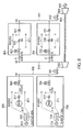
- FIG. 7 is a diagram illustrating a configuration example of a multiaxial type combined cycle power plant of a 2-2-1 manner relating to the comparative example.
- the multiaxial type combined cycle power plant of the 2-2-1 manner relating to a first comparative example includes first units 700 and 701, second units 800 and 801, a high pressure steam header 908, a regulating valve 901, a high pressure steam turbine (first steam turbine) 902, a low pressure steam turbine (second steam turbine) 903, an intercept valve 912, an axle 904, and a generator 905.
- the first unit 700 includes a generator 716, a first gas turbine 710, a heat recovery steam generator 711, a drum 713, a first superheater 717, and a high pressure isolation valve 704.
- the second unit 800 includes a generator 816, a second gas turbine 810, a heat recovery steam generator 811, a drum 813, a second superheater 817, and a high pressure isolation valve (third valve) 804.
- the heat recovery steam generator 711 of the first unit 700 recovers heat of exhaust gas of the first gas turbine 710, and generates steam from the built-in drum 713.
- the steam is heated by the first superheater 717, and first main steam "n" is generated.
- the heat recovery steam generator 811 of the second unit 800 similarly recovers heat of exhaust gas of the second gas turbine 810, and generates steam from the built-in drum 813.
- the steam is heated by the second superheater 817, and second main steam "k" is generated.
- the first main steam “n” from the first unit 700 and the second main steam “k” from the second unit 800 are sent to the high pressure steam header 908 through the high pressure isolation valves 704 and 804 respectively.
- the main steam “n” and the main steam “k” are merged in the high pressure steam header 908, then pass through the regulating valve 901, are supplied to the high pressure steam turbine 902, and drive the high pressure steam turbine 902.
- the main steam "n” and the main steam “k” become discharge steam in a low pressure and low temperature state by driving the high pressure steam turbine 902.
- the discharge steam is exhausted from the high pressure steam turbine 902, and sent to a discharge steam header 910. Since the first unit 701 and the second unit 702 are branched from the discharge steam header 910, the discharge steam is divided into first discharge steam "p" of the first unit and second discharge steam "q" of the second unit respectively.
- a first reheater 720 built into the heat recovery steam generator 711 of the first unit generates first reheat steam "y” by recovering the heat of the exhaust gas of the first gas turbine 710 and heating the first discharge steam "p".
- a second reheater 820 built into the heat recovery steam generator 811 of the second unit generates second reheat steam "z” by recovering the heat of the exhaust gas of the second gas turbine 810 and heating the second discharge steam "q”.
- the first reheat steam "y" of the first unit and the second reheat steam “z” of the second unit are sent to a reheat steam header 911 through check valves 721 and 821 respectively.
- the first reheat steam "y” of the first unit and the second reheat steam “z” of the second unit are merged in the reheat steam header 911, pass through the intercept valve 912, are supplied to the low pressure steam turbine 903, and drive the low pressure steam turbine 903.
- the high pressure isolation valves 704 and 804 that are motor-operated valves are installed respectively. Also, between the discharge steam header 910 and the first and second reheaters 720 and 820, CRT (Cold ReHeat: low temperature reheat) isolation valves 722 and 822 that are motor-operated valves are installed respectively. All four of the high pressure isolation valves 704 and 804 and the CRT isolation valves 722 and 822 are fully open at a 100% opening degree.
- FIG. 7 illustrates an operation situation that both of the first and second gas turbines 710 and 810 of the first unit and the second unit are operated at the rated 100% output. Since the first gas turbine 710 of the first unit 700 is at the rated 100% output, a large amount of gas turbine exhaust gas at a high temperature is received, and a flow rate of the main steam "n" generated by the heat recovery steam generator is F (t/h).
- a flow rate of the main steam "k” is the same F (t/h). Since it is gathered to drive the high pressure steam turbine 902, and is then equally divided, the first discharge steam "p” and the second discharge steam “q” are F (t/h) respectively. In this way, since the first discharge steam "p” and the second discharge steam “q” at the sufficient flow rate of F (t/h) pass through the first and second reheaters 720 and 820 respectively, there is no trouble in cooling the first and second reheaters 720 and 820.
- FIG. 8 is a diagram for describing the steam flow rate in the unbalanced output state of the multiaxial type combined cycle power plant of the 2-2-1 manner relating to the comparative example.
- the second gas turbine 810 of the second unit 800 is at 40% output of a partial output state. In this way, the first gas turbine 710 of the first unit 700 and the second gas turbine 810 of the second unit 800 are operated in the unbalanced output state.
- the total flow rate of the discharge steam that flows into the discharge steam header 910 is equal to a total value of the main steam "n" and the main steam "k"
- a flow rate of a fluid passing through a valve body depends on a differential pressure of an entrance pressure (primary pressure) and an exit pressure (secondary pressure) of the valve, that is, a valve differential pressure.
- the primary pressure of the valve is equal since it is a pressure of the discharge steam header 910 in both units, and the secondary pressure is also substantially equal since the secondary pressure of the valve is the pressure for which pressure loss that the individual first and second reheaters 720 and 820 have is added to the pressure of the reheat steam header 911. Since the primary pressure and the secondary pressure are equal and the valve opening degree is the 100% opening degree of full open in both, the equal discharge steam amount flows into the first and second reheaters 720 and 820 of the individual units.
- the flow rate of the first discharge steam "p" is reduced by 25% from F (t/h) that guarantees a cooling effect and is lowered to 3/4F (t/h). Therefore, cooling of the first reheater 720 becomes insufficient and a problem that a temperature of the first reheater 720 exceeds a highest using temperature of the first reheater 720 arises.
- the discharge steam is taken by the second unit 801 so that the discharge steam flow rate of itself is lowered.
- an amount of the discharge steam equal to that of the main steam is to be secured for each heat recovery steam generator. That is, when the second discharge steam "q" of 3/4F (t/h) flowing into the second reheater 820 of the second unit 801 is reduced to 1/2F (t/h) that is the same as the main steam "k", the flow rate of the first discharge steam "p" of the first unit is increased from 3/4F (t/h) to F (t/h). In this way, it is recognized that the problem is solved. Then, in order to achieve this, it is recognized that the opening degree of the CRH isolation valve 822 should be narrowed to an intermediate opening degree.
- the CRH isolation valve 822 is a motor-operated valve, and a main installation purpose thereof is use in "interruption and insertion of steam" in activation of a subsequent unit or the like to be described later, and the purpose is not the flow rate control.
- the CRH isolation valve 822 is, for example, the motor-operated valve of a large size installed in large diameter piping of a diameter being about 500 mm to 700 mm, and the time of about two minutes is needed for the stroke time (the shortest time needed from full close to full open).
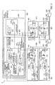
- FIG. 1 is a diagram illustrating a configuration of a multiaxial type combined cycle power plant 1 of the 2-2-1 manner relating to the first embodiment.
- an operation condition of the multiaxial type combined cycle power plant 1 of the 2-2-1 manner relating to the first embodiment is such that, similarly to FIG. 8 , the first gas turbine 710 of the first unit keeps the rated 100% output, the first main steam "n” is the flow rate of F (t/h), and the opening degree of the CRH isolation valve 722 is 100% fully open.
- the output of the second gas turbine 810 of the second unit 800 is lowered to 40% output, and the second main steam "k” is lowered to the flow rate of 1/2F (t/h).
- an object is to adjust the CRH isolation valve 822 so that the flow rate of the second discharge steam "q" becomes 1/2F (t/h) and increase the first discharge steam "p" of the first unit to F (t/h).
- a control apparatus 300 relating to the present embodiment executes the following processing.
- the control apparatus 300 relating to the present embodiment obtains a flow rate ratio (for example, 1:0.5) of the first main steam "n" and the second main steam "k", and adjusts the CRH isolation valve 822 so as to proportionately divide the flow rate ratio of the discharge steam between the first unit 701 and the second unit 801 to be the same ratio (for example, 1:0.5) as the obtained flow rate.
- a flow rate ratio for example, 1:0.5
- the control apparatus 300 relating to the present embodiment obtains a flow rate ratio (for example, 1:0.5) of the first main steam "n" and the second main steam "k”, and adjusts the CRH isolation valve 822 so as to proportionately divide the flow rate ratio of the discharge steam between the first unit 701 and the second unit 801 to be the same ratio (for example, 1:0.5) as the obtained flow rate.
- the opening degree of the CRH isolation valve 822 becomes 30% for example.
- the plant control apparatus 300 determines a valve opening degree of the CRH isolation valve 822 using the flow rate ratio of the first main steam “n” and the second main steam “k” and correspondence between the valve opening degree and the flow coefficient (Cv value) of the CRH isolation valve 822, so as to easily handle an element parameter that is the flow rate ratio of the steam.
- the configuration of the multiaxial type combined cycle power plant 1 relating to the first embodiment illustrated in FIG. 1 is the configuration for which a measuring instrument 718 is added to the first unit 700, a measuring instrument 818 is added to the second unit 800, an opening degree meter 815 is added to the second unit 801, and the plant control apparatus 300 is added, compared to the multiaxial type combined cycle power plant relating to the comparative example illustrated in FIG. 7 .
- the measuring instrument 718 measures the flow rate of the first main steam "n". Also, the measuring instrument 818 measures the flow rate of the second main steam "k”.
- the opening degree meter 815 measures the valve opening degree of the CRH isolation valve (second valve) 822. The description will be given hereinafter, assuming that the CRH isolation valve (second valve) 822 in the present embodiment is a motor-operated valve as one example.
- the control apparatus 300 includes a valve controller 600.
- the valve controller 600 includes a processor not shown in the figure and a storage unit not shown in the figure, in which a program is stored, and the processor executes the program stored in the storage unit. Accordingly, the valve controller 600 controls the high pressure isolation valves 704 and 804 and the CRH isolation valves 722 and 822 for example. In FIG. 1 , only elements that control the CRH isolation valve 822 among them are illustrated.
- the valve controller 600 functions as a determination module 601 and a controller 602.
- the determination module 601 determines a target opening degree of the CRH isolation valve (second valve) 822 using the flow rate of the first main steam "n" and the flow rate of the second main steam "k".
- the controller 602 compares the determined target opening degree with the valve opening degree of the CRH isolation valve (second valve) 822, and controls the CRH isolation valve (second valve) 822 based on a comparison result.
- the determination module 601 includes a divider 610, a moving time average operator 612, and a function generator 614. Also, the controller 602 includes a comparator 615 and a comparator 616. To the determination module 601 of the valve controller 600, a flow rate signal "e” indicating the flow rate of the main steam "n”, that is obtained by being measured by the measuring instrument 718, and a flow rate signal “m” indicating the flow rate of the main steam "k”, that is obtained by being measured by the measuring instrument 818, are inputted.
- the moving time average operator 612 calculates a moving time average of the flow rate ratio "i" in recent stipulated time (for example, one minute) as a main steam average flow rate ratio "h", and outputs the calculated main steam average flow rate ratio "h" to the function generator 614.
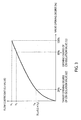
- FIG. 2 is a graph illustrating one example of a characteristic of the valve opening degree and the flow coefficient of the CRH isolation valve 822 relating to the first embodiment.
- a vertical axis is the flow coefficient (Cv value)
- a horizontal axis is the valve opening degree.
- the flow coefficient (Cv value) is the flow rate of the CRH isolation valve 822 obtained from the main steam average flow rate ratio "h".
- the function generator 614 stores the correspondence between the valve opening degree and the flow coefficient (Cv value) of the CRH isolation valve 822, indicating the characteristic as in FIG. 2 .
- the function generator 614 determines a target flow coefficient Y2 of the CRH isolation valve (second valve) 822 from the main steam average flow rate ratio "h", and determines the valve opening degree (for example, 30% in the example in FIG. 2 ) of the CRH isolation valve (second valve) corresponding to the target flow coefficient Y2 of the CRH isolation valve (second valve) 822 in the correspondence (see FIG. 2 ) between the valve opening degree and the flow coefficient (Cv value), as a target opening degree "r" of the CRH isolation valve (second valve) 822.
- the determination module 601 calculates the moving time average of the flow rate ratio of the first main steam and the second main steam as the main steam average flow rate ratio "h", and determines the target opening degree of the CRH isolation valve (second valve) 822 using the calculated main steam average flow rate ratio "h” and the correspondence between the valve opening degree and the flow coefficient of the CRH isolation valve (second valve) 822.
- the determination module 601 determines the target flow coefficient of the CRH isolation valve (second valve) 822 using the main steam average flow rate ratio "h", and determines the valve opening degree of the CRH isolation valve (second valve) 822 corresponding to the target flow coefficient of the CRH isolation valve (second valve) 822 in the correspondence between the valve opening degree and the flow coefficient, as the target opening degree "r" of the CRH isolation valve (second valve) 822.
- CRH isolation valve 722 and CRH isolation valve 822 are the valves of the same standard as one example, the correspondence between the valve opening degree and the flow coefficient (Cv value) is also the same.
- the function generator 614 outputs the determined target opening degree "r" to the comparator 615 and the comparator 616.
- an opening degree signal "d" indicating the opening degree of the CRH isolation valve 822, which is measured by the opening degree meter 815, is inputted.
- the comparator 615 compares the target opening degree "r” with the opening degree signal "d", and in the case that the target opening degree "r” is larger than the opening degree signal "d" (that is, in the case of r>d), outputs a valve opening command "v" to the CRH isolation valve 822.
- the comparator 616 compares the target opening degree "r” with the opening degree signal "d", and in the case that the target opening degree "r” is smaller than the opening degree signal "d" (that is, in the case of r ⁇ d), outputs a valve closing command "w” to the CRH isolation valve 822.
- the controller 602 outputs the valve opening command "v” when the opening degree is insufficient, and the valve closing command "w” when the opening degree is excessive according to the target opening degree "r". Accordingly, the opening degree of the CRH isolation valve 822 finally becomes the target opening degree "r".
- the first gas turbine 710 of the first unit 700 keeps the rated 100% output, the CRH isolation valve 722 is fully open, and the main steam "n” flows at the flow rate of F (t/h).
- the second gas turbine 810 of the second unit 800 is lowered to the 40% output, and the main steam "k” flows at the flow rate of 1/2F (t/h). The operation and effect in FIG. 1 in this state will be described.
- the divider 610 divides the flow rate signal "m” by the flow rate signal "e", and outputs the main steam flow rate ratio "i" whose value indicates 0.5.
- the steam flow rate in an actual plant receives various disturbance elements, noise components are impressed, and the flow rate signals "e” and “m” fluctuate in a range of about ⁇ 5% at all times. Accordingly, the main steam flow rate ratio "i" also has the fluctuation of about ⁇ 10% with 0.5 roughly at the center.
- the function generator 614 stores the correspondence between the valve opening degree and the flow coefficient (Cv value) of the CRH isolation valve 822 in the inside. For example, when the main steam average flow rate ratio "h" whose value indicates 0.5 is inputted, the function generator 614 acquires a flow coefficient Y1 for the time when the valve opening degree is 100%, since the valve opening degree of the CRH isolation valve 722 is 100%, based on the correspondence between the valve opening degree and the flow coefficient of the CRH isolation valve 822 held inside.
- the function generator 614 Since the main steam average flow rate ratio "h" is 0.5, the function generator 614 obtains the valve opening degree of the valve to be the flow coefficient Y2 which is 0.5 times the flow coefficient Y1 based on the correspondence between the valve opening degree and the flow coefficient of the CRH isolation valve 822. Therefore, 30% can be obtained as the target opening degree "r".
- the present embodiment can demonstrate such an effect while using the motor-operated value by adopting not flow rate control intended to directly turn an actual flow rate of the second discharge steam "q" to desired 1/2F (t/h), but control that the flow rate ratio of the first discharge steam "p” and the second discharge steam “q” is divided into 1:0.5 and the second discharge steam "q” "indirectly” becomes 1/2F (t/h) as a result.
- the multiaxial type combined cycle power plant 1 includes the first superheater 717 that recovers the heat of the exhaust gas of the first gas turbine 710 and generates the first main steam, and the second superheater 817 that recovers the heat of the exhaust gas of the second gas turbine 810 and generates the second main steam.
- the multiaxial type combined cycle power plant 1 includes the first steam turbine 902 that the first main steam and the second main steam flow into, the first reheater 720 that heats the first discharge steam for which the discharge steam of the first steam turbine 902 is divided and generates the first reheat steam, and the second reheater 820 that heats the second discharge steam for which the discharge steam of the first steam turbine 902 is divided and generates the second reheat steam.
- the multiaxial type combined cycle power plant 1 includes the second steam turbine 903 that the first reheat steam and the second reheat steam flow into after being merged, the CRH isolation valve (first valve) 722 that adjusts the flow rate of the first discharge steam flowing into the first reheater, and the CRH isolation valve (second valve) 822 that adjusts the flow rate of the second discharge steam flowing into the second reheater 820.
- the plant control apparatus 300 that controls the multiaxial type combined cycle power plant 1 having such a configuration includes the determination module 601 that determines the target opening degree "r" of the CRH isolation valve (second valve) 822, using the flow rate of the first main steam and the flow rate of the second main steam. Further, the plant control apparatus 300 includes the controller 602 that compares the determined target opening degree with the valve opening degree of the CRH isolation valve (second valve) 822, and controls the CRH isolation valve (second valve) 822 based on the comparison result.
- the valve differential pressure of the first valve and the second valve becomes equal, so that the ratio of the steam flow rates passing through both valves is the ratio of the flow coefficients of both valves.
- the determination module 601 determines the target opening degree "r" of the CRH isolation valve (second valve) 822 so that the ratio of the steam flow rates passing through both valves becomes the same as the flow rate ratio of the first main steam and the second main steam. Then, the controller 602 controls the CRH isolation valve (second valve) 822 so that the valve opening degree of the CRH isolation valve (second valve) 822 becomes the target opening degree.
- the ratio of the steam flow rates passing through the CRH isolation valve 722 and the CRH isolation valve 822 becomes the flow rate ratio of the first main steam and the second main steam.
- control manner relating to the first embodiment is applicable also to a multiaxial type combined cycle power plant of a 3-3-1 manner of combining three gas turbines, three heat recovery steam generators, and one steam turbine.
- the plant control apparatus 300 adjusts the CRH isolation valve of the second unit according to the main steam flow rate ratio of the first unit and the second unit, and similarly adjusts the CRH isolation valve of the third unit according to the main steam flow rate ratio of the first unit and the third unit.
- the flow rate of the discharge steam can be divided among the first unit, the second unit and the third unit according to the flow rate ratio of the main steam among the first unit, the second unit and the third unit.
- the control manner relating to the first embodiment is applicable also to a multiaxial type combined cycle power plant of an N-N-1 manner of combining N (N is a natural number) gas turbines, N heat recovery steam generators, and one steam turbine.
- FIG. 3 is a graph illustrating one example of the characteristic of the valve opening degree and the flow coefficient of the CRH isolation valve 822 relating to the second modification of the first embodiment.
- a vertical axis is the flow coefficient (Cv value)
- a horizontal axis is the valve opening degree.
- the CRH isolation valve of a unit (here, the first unit 701) on the side where the output of the gas turbine is large is at 100%.
- the reason is that, when use is performed when the opening degree of the CRH isolation valve is full open or less, pressure loss becomes large, the temperature and pressure of the discharge steam are lowered, and the output of the low pressure steam turbine 903 is lowered for that, leading to economical loss as a commercial machine.
- the CRH isolation valve of the unit on the large output side is operated at an intermediate opening degree.
- the multiaxial type combined cycle power plant 1 in the second modification of the first embodiment includes an opening degree meter (not shown in the figure) that measures the opening degree of the CRH isolation valve 722 further for the multiaxial type combined cycle power plant 1 in FIG. 1 .
- the opening degree meter outputs an opening degree signal indicating the opening degree of the CRH isolation valve 722 to the determination module 601.
- the function generator 614 built into the determination module 601 of the present modification obtains the target opening degree "r" of the CRH isolation valve 822 of the second unit (the small output side) by a following procedure.
- the determination module 601 obtains the flow coefficient corresponding to the valve opening degree of the first valve in the correspondence between the valve opening degree and the flow coefficient (Cv value) of the CRH isolation valves 722 and 822, and determines the target flow coefficient Y4 of the CRH isolation valve (second valve) 822 using the obtained flow coefficient and the main steam average flow rate ratio "h".
- the determination module 601 determines the valve opening degree of the CRH isolation valve (second valve) 822 corresponding to the target flow coefficient Y4 of the CRH isolation valve (second valve) 822 in the correspondence between the valve opening degree and the flow coefficient (Cv value) of the CRH isolation valves 722 and 822, as the target opening degree "r" of the CRH isolation valve (second valve) 822.
- the ratio of the steam flow rates passing through the CRH isolation valve 722 and the CRH isolation valve 822 becomes the flow rate ratio of the first main steam and the second main steam.
- the CRH isolation valve (first valve) 722 is provided before the first reheater 720 to adjust the flow rate of first exhaust steam flowing into the first reheater
- the CRH isolation valve (second valve) 822 is provided before the second reheater 820 to adjust the flow rate of second exhaust steam flowing into the second reheater 820.
- a CRH isolation valve (first valve) 732 is provided after the first reheater 720 to adjust the flow rate of the first reheat steam discharged from the first reheater 720
- a CRH isolation valve (second valve) 832 is provided after the second reheater 820 to adjust the flow rate of the second reheat steam discharged from the second reheater 820.
- FIG. 4 is a diagram illustrating a configuration of the multiaxial type combined cycle power plant 2 of the 2-2-1 manner relating to the second embodiment. The same signs are attached to elements in common with FIG. 1 , and the specific description will be omitted. As illustrated in FIG. 4 , the configuration of the multiaxial type combined cycle power plant 2 of the 2-2-1 manner relating to the second embodiment is different in the following points, compared to the configuration of the multiaxial type combined cycle power plant 1 relating to the first embodiment illustrated in FIG. 1 .
- Check valves 731 and 831 are provided respectively between the discharge steam header 910 and the first and second reheaters 720 and 820, and HRH (Hot ReHeat: high temperature reheat) isolation valves 732 and 832 are provided between the first and second reheaters 720 and 820 and the reheat steam header 911. Accordingly, the HRH isolation valve (first valve) 732 adjusts the flow rate of the first reheat steam discharged from the first reheater 720. Also, the HRH isolation valve (second valve) 832 adjusts the flow rate of the second reheat steam discharged from the second reheater 820. Further, an opening degree meter 825 that measures the opening degree of the HRH isolation valve 832 is provided.
- the control apparatus 300 in the first embodiment controls the CRH isolation valve 822 using the opening degree of the CRH isolation valve 822.
- the control apparatus 300 in the second embodiment uses the opening degree of the HRH isolation valve 832 instead of the opening degree of the CRH isolation valve 822. Then, a control target is also changed from the CRH isolation valve 822 to the HRH isolation valve 832.
- the control apparatus 300 in the second embodiment obtains the flow rate ratio of the main steam between the first unit 700 and the second unit 800 based on the control manner of the first embodiment, and adjusts the opening degree of the HRH isolation valve 832 so as to divide the flow rate ratio of the reheat steam between the first unit 701 and second unit 801 accordingly.
- the opening degree of the HRH isolation valve 832 becomes 30% for example.
- the multiaxial type combined cycle power plant 1 in the first embodiment using the CRH isolation valve that handles the discharge steam of a low temperature is preferable.
- the valve controller 600 may determine the target opening degree of both isolation valves using the flow rate ratio of the first main steam and the second main steam and the correspondence between the valve opening degree and the flow coefficient (Cv value) of combination when the two motor-operated valves are serially configured, and control both isolation valves so that both isolation valves are turned to the determined target opening degree.
- FIG. 5 is a diagram illustrating a configuration of the multiaxial type combined cycle power plant 3 of the 2-2-1 manner relating to the third embodiment.
- the configuration of the multiaxial type combined cycle power plant 3 in the third embodiment is the one for which, to the configuration of the multiaxial type combined cycle power plant 1 in the first embodiment, turbine bypass valves 723 and 823 are added, an opening degree meter 819 that measures the valve opening degree of the high pressure isolation valve 804 is added, and the control apparatus 300 is changed to a control apparatus 400.
- the control apparatus 400 includes a valve controller 650.
- the present embodiment is a case of applying the control manner relating to the first embodiment to a process of additionally activating the gas turbine 810 of the second unit 800 after the second units 800 and 801 are restored and returning to the configuration of the combined cycle power plant of the 2-2-1 manner from the operation condition (this is called the late unit activation).
- the first gas turbine 710 of the first unit 700 is in a rated 100% output operation pursuing economic efficiency as a commercial operation in the operation state of the 1-1-1 manner as it is.
- the second gas turbine 810 of the second unit 800 is activated after being restored, however, since the CRH isolation valve 822 is initially in a fully closed state at the time, the flow rate of the second discharge steam "q" is zero, that is, a cooling medium passing through the second reheater 820 is zero.
- the second gas turbine 810 is turned to a rated 100% output state in this state, a problem of cooling of the second reheater 820 arises due to the high gas turbine exhaust gas temperature. Then, output of the gas turbine 810 of the second unit 800 is limited to the largest gas turbine output (for example, 40% output, the 40% is a numerical value for the convenience of the description) that the second reheater 820 can withstand when there is no flow rate of the second discharge steam "q". For this reason, in the late unit activation, the unbalanced output operation that the second unit is 40% to the rated 100% of the first unit is forced.
- the largest gas turbine output for example, 40% output, the 40% is a numerical value for the convenience of the description
- the cooling insufficiency of the first reheater 720 of the first unit 701 becomes a problem due to the output unbalance between the gas turbine 710 of the first unit 700 and the gas turbine 810 of the second unit 800.
- the late unit activation is performed after deliberately lowering the gas turbine 710 of the first unit 700 operated at the rated 100% output to the 40% output, and matching the output of the gas turbine 710 of the first unit 700 and the gas turbine 810 of the second unit 800.
- the late unit activation that reduces the possibility that the first reheater 720 of the first unit is insufficiently cooled becomes possible even in the unbalanced state that the output of the gas turbine 810 of the second unit 800 is 40% while keeping the gas turbine 710 of the first unit 700 at the 100% output.
- the first gas turbine 710 of the first unit 700 is operated at the rated 100% output. Then, the high pressure isolation valve 704 and the CRH isolation valve 722 are both 100% fully open, and the flow rate of F (t/h) flows respectively for the main steam "n" and the first discharge steam "p". On the other hand, the second gas turbine 810 of the second unit 800 is stopped. Then, the high pressure isolation valve 804 and the CRH isolation valve 822 are both fully closed to prevent the steam of the first units 700 and 701 from flowing into the second units 800 and 801. At the time, a tight shutting property of the above-described motor-operated valves is required.
- the second gas turbine 810 of the second unit 800 is additionally activated and the process of the late unit activation is started, the second gas turbine 810 is activated first and the output is raised to the 40% output.
- the main steam "k” generated immediately after the activation is insufficient in the temperature, a pressure and the flow rate, and cannot be supplied to the high pressure steam turbine 902.
- the high pressure isolation valve 804 is fully closed, the turbine bypass valve 823 is opened instead through pressure control of appropriately keeping an intra-device pressure of the drum 813, and the main steam "k” is released to a steam condenser (not shown in the figure).
- the flow rate of the main steam "k” is defined as 1/2F (t/h).
- the determination module 601 is changed to a determination module 651, and the controller 602 is changed to a controller 652.
- a sample-hold unit 613 compared to the configuration of the determination module 601 in the first embodiment, a sample-hold unit 613 a switch 617, a judgement module 618, a setter 620, a comparator 621, a pulse generator 622, and an AND gate 623 are added.
- an AND gate 619 is added and the comparator 616 is eliminated.
- the judgement module 618 considers the temperature or pressure or the like of the second main steam generated by the second superheater 817, judges that it is possible to insert the second main steam, and turns an insertion start signal "g" indicating second unit insertion start to 1.
- the insertion start signal "g” is inputted to the pulse generator 622, and the pulse generator 622 generates a pulse signal "b" to be a high level only for a second stipulated interval in every first stipulated interval (for example, to be the high level only for one second in every 10 seconds) for example, and outputs the pulse signal "b" to the AND gate 619.
- an opening degree signal "j" indicating the opening degree of the high pressure isolation valve 804 measured by the opening degree meter 819 is inputted.
- the AND gate 623 generates a valve opening command "c" commanding valve opening to the high pressure isolation valve 804 by ANDing the opening degree increase command "u” and the pulse signal "b", and outputs the generated valve opening command "c" to the high pressure isolation valve 804.
- the high pressure isolation valve 804 is gradually opened, and the high pressure isolation valve 804 finally becomes 100% fully open from being fully closed.
- the opening degree increase command "u” becomes 0 and the valve opening command "c" is turned off.
- the flow rate signal "e” indicating the flow rate of the main steam “n” measured by the measuring instrument 718 and the flow rate signal “m” indicating the flow rate of the main steam “k” measured by the measuring instrument 818 are inputted.
- the main steam flow rate ratio "i” is outputted from the divider 610 and inputted to the moving time average operator 612.
- the moving time average operator 612 calculates the moving time average of the main steam flow rate ratio "i" in the recent predetermined time (for example, one minute) as the main steam average flow rate ratio "h".
- the main steam average flow rate ratio "h” is outputted from the moving time average operator 612 and inputted to the sample-hold unit 613 and the switch 617.
- the sample-hold unit 613 stores the main steam average flow rate ratio "h” at a moment when the insertion start signal "g" becomes 1, and outputs this value as an insertion start time main steam flow rate ratio "s". Therefore, after this processing, the insertion start time main steam flow rate ratio "s" becomes a fixed value.
- the switch 617 switches a corrected main steam flow rate ratio "t” which is an output value thereof between the insertion start time main steam flow rate ratio "s” and the main steam average flow rate ratio "h” according to the value of the opening degree increase command "u". Specifically, the switch 617 outputs the insertion start time main steam flow rate ratio "s” as the corrected main steam flow rate ratio "t” when the opening degree increase command "u” is 1, and outputs the main steam average flow rate ratio "h” as the corrected main steam flow rate ratio "t” when the opening degree increase command "u” is 0.
- the insertion start time main steam flow rate ratio "s” is outputted as the corrected main steam flow rate ratio "t"
- the main steam average flow rate ratio "h” is outputted as the corrected main steam flow rate ratio "t”.
- the outputted corrected main steam flow rate ratio "t” is inputted to the function generator 614.
- the function generator 614 determines the target opening degree "r" of the CRH isolation valve 822 using the corrected main steam flow rate ratio "t” and the correspondence between the valve opening degree and the flow coefficient (Cv value) of the CRH isolation valve 822.
- the determined target opening degree "r” is outputted from the function generator 614 and inputted to the comparator 615.
- the opening degree signal "d” indicating the opening degree of the CRH isolation valve 822 measured by the opening degree meter 815 is inputted.
- the comparator 615 compares the inputted target opening degree “r” with the inputted opening degree signal "d”, and when the target opening degree "r” is larger than the opening degree signal "d" (that is, when it is r>d), outputs an opening degree increase command "v" to the CRH isolation valve 822.
- the AND gate 619 generates a valve opening command "a” to the CRH isolation valve 822 by ANDing the opening degree increase command "v" and the pulse signal "b". Then, the generated valve opening command "a” is outputted to the CRH isolation valve 822. By such a configuration, the CRH isolation valve 822 is finally opened at the target opening degree "r" from being fully closed.
- the controller 652 in the present embodiment does not include the comparator 616 included in the first embodiment.
- the high pressure isolation valve 804 is opened by the valve opening command "c"
- the main steam "k” is sent to the high pressure steam header 908, and the main steam “k” is inserted through the regulating valve 901 to the high pressure steam turbine 902.
- the valve controller 650 can send the main steam "k” to the high pressure steam header 908 more effectively by forcibly closing the turbine bypass valve 823 by control not shown in the figure.
- the pulse generator 622 is conventionally provided, and the valve opening command "c" to the high pressure isolation valve 804 is outputted in a pulse shape of one second in 10 seconds. That is, the high pressure isolation valve 804 is fully opened while repeating a motor pause of nine seconds after the valve is opened by motor drive for one second. This is called an inching valve opening manner. In this way, the high pressure isolation valve 804 is opened at a slow speed of about 1/10 compared to a normal case of continuously driving a motor.
- the sample-hold unit 613 stores the main steam average flow rate ratio "h” at the moment when the insertion start signal "g” becomes 1, and outputs it as the insertion start time main steam flow rate ratio "s".
- the main steam average flow rate ratio "h” at the moment when the insertion start signal "g” becomes 1 is the main steam average flow rate ratio "h” in a stable state immediately before the high pressure isolation valve 804 is opened.
- the insertion start time main steam flow rate ratio "s” in this case is 0.5 similarly to FIG. 1 as one example, and since the opening degree increase command "u" is 1, the switch 617 outputs the insertion start time main steam flow rate ratio "s” whose value indicates 0.5 as the corrected main steam flow rate ratio "t".
- a period during which the opening degree increase command "u" is 1 is the period until the high pressure isolation valve 804 is fully opened from being fully closed while repeating motor drive valve opening of one second and the motor pause of nine seconds.
- the flow rate ratio of the main steam "n” and the main steam “k” largely fluctuates.
- the sample-hold unit 613 stores the insertion start time main steam flow rate ratio "s” whose value is 0.5, even when the actual flow rates of the main steam "n” and the main steam “k” fluctuate, the corrected main steam flow rate ratio "t” is fixed at 0.5.
- the function generator 614 obtains the valve opening degree of the valve to be the flow coefficient Y2 that is 0.5 times the flow coefficient Y1 for the time when the valve is 100% fully open, based on the correspondence between the valve opening degree and the flow coefficient indicating the characteristic in FIG. 2 held inside similarly to FIG. 1 , as the target opening degree (for example, 30%) "r".
- the CRH isolation valve 822 is opened while repeating the motor pause of nine seconds after the valve is opened by motor drive for one second by the operation of the pulse generator 622 similarly to the high pressure isolation valve 804, and is finally turned to the 30% opening degree.
- the quick opening of the CRH isolation valve 822 causes the rapid insertion of the second discharge steam "q" to the low pressure steam turbine 903, turbine thrust force suddenly changes, and adverse influence is given, so that the CRH isolation valve 822 is also subjected to inching valve opening similarly to the high pressure isolation valve 804.
- the second discharge steam "q" is overheated while flowing into the second reheater 820, becomes the second reheat steam "z", sent to the reheat steam header 911, and inserted to the low pressure steam turbine 903.
- the CRH isolation valve 822 is open at 30%.
- a state is such that the high pressure isolation valves 704 and 804 and the CRH isolation valve 722 are fully open at the 100% opening degree, and the opening degree of the CRH isolation valve 822 becomes 30% for example.
- the second discharge steam "q" of the second unit 801 is 1/2F (t/h)
- the first discharge steam "p" of the first unit 701 is F (t/h). Therefore, since the sufficient amount of the discharge steam passing through the first reheater 720 can be secured, the possibility that the first reheater 720 is insufficiently cooled can be reduced.
- the multiaxial type combined cycle power plant 3 includes a third valve 804 that is provided between the second superheater 817 and the first steam turbine 902 and adjusts the flow rate of the second main steam.
- the determination module 651 determines the target opening degree "r" of the second valve 822 using the flow rate ratio of the first main steam and the second main steam and the correspondence between the valve opening degree and the flow coefficient of the second valve 822 when the third valve 804 is opened.
- the determination module 651 determines the target opening degree of the second valve 822 using the flow rate ratio of the first main steam and the second main steam and the correspondence between the valve opening degree and the flow coefficient of the second valve 822 at the determination time.
- the second valve 822 is controlled so as to be at the target opening degree (for example, 30%). Accordingly, the flow rate ratio of the first discharge steam "p" of the first unit 701 and the second discharge steam "q" of the second unit 801 is maintained in the same state as the flow rate ratio of the first main steam and the second main steam. As a result, since the sufficient amount of the discharge steam passing through the first reheater 720 can be secured, the possibility that the first reheater 720 is insufficiently cooled can be reduced.
- control is performed to be the target opening degree according to the flow rate ratio of the first main steam and the second main steam at the control time. Accordingly, the flow rate ratio of the first discharge steam "p" of the first unit 701 and the second discharge steam “q” of the second unit 801 is maintained in the same state as the flow rate ratio of the first main steam and the second main steam. As a result, since the sufficient amount of the discharge steam passing through the first reheater 720 can be secured, the possibility that the first reheater 720 is insufficiently cooled can be reduced.
- the control apparatus 400 may include the valve controller 650 and the valve controller 600, the valve controller 650 may be switched to the valve controller 600, and the valve controller 600 may control the CRH isolation valve 822.
- the valve controller 600 does not include the pulse generator built into the valve controller 650, however, the fluctuation of the main steam flow rate which occurs accompanying increase/decrease of the gas turbine output is much gentler than that during the valve opening operation of the high pressure isolation valve, and there is no problem.
- the present modification is an application case relating to the late unit activation of the multiaxial type combined cycle power plant of the 2-2-1 manner called the so-called cascade bypass manner.
- the valve controller 650 obtains the flow rate ratio of the first main steam and the second main steam immediately before the high pressure isolation valve 804 is opened as the insertion start time main steam flow rate ratio "s".
- the valve controller 650 obtains and stores the flow rate ratio of the first discharge steam "p" and the second discharge steam "q" immediately before the high pressure isolation valve 804 is opened as a discharge steam flow rate ratio, and adjusts the CRH isolation valve (second valve) 822 so as to divide the flow rate of the discharge steam between the first unit 701 and the second unit 801 according to the stored discharge steam flow rate ratio.
- FIG. 6 is a diagram illustrating a configuration of a multiaxial type combined cycle power plant 3b of the 2-2-1 manner relating to the modification of the third embodiment. The same signs are attached to elements in common with FIG. 5 , and the specific description will be omitted. As illustrated in FIG. 6 , the configuration of the multiaxial type combined cycle power plant 3b relating to the present modification is different in the following points, compared to the configuration of the multiaxial type combined cycle power plant 3 relating to the third embodiment illustrated in FIG. 5 .
- the multiaxial type combined cycle power plant 3b relating to the present modification includes a high pressure turbine bypass valve 833 and a low pressure turbine bypass valve 834 instead of the turbine bypass valve 823, and the HRH isolation valve 832 is added.
- the multiaxial type combined cycle power plant 3b relating to the present modification includes a high pressure turbine bypass valve 733 and a low pressure turbine bypass valve 734 instead of the turbine bypass valve 723, and the HRH isolation valve 732 is added.
- the multiaxial type combined cycle power plant 3b relating to the present modification includes a measuring instrument 728 that measures the flow rate of the first discharge steam "p" and a measuring instrument 828 that measures the flow rate of the second discharge steam "q", instead of the measuring instruments 718 and 818.
- the generated main steam "k” passes through the high pressure turbine bypass valve 833, the second reheater 820 and the low pressure turbine bypass valve 834 in order and is led to the steam condenser (not shown in the figure).
- the generated second main steam "k” surely becomes the second discharge steam "q". Therefore, in the cascade bypass manner, the flow rate of the main steam "k” before the insertion to the high pressure steam turbine 902 of the second main steam “k” is started coincides with the second discharge steam "q” measured by the measuring instrument 828. Accordingly, it can be said that the measuring instrument 828 is measuring the flow rate of the second main steam "k” when the high pressure isolation valve 804 is fully closed and the CRH isolation valve 822 is fully closed.
- the measuring instrument 728 is measuring the flow rate of the first main steam "n” when the high pressure isolation valve 804 is fully closed and the CRH isolation valve 822 is fully closed.
- the flow rate signal "e” indicating the flow rate of the first discharge steam “p” measured by the measuring instrument 728 is inputted, and the flow rate signal “m” indicating the flow rate of the second discharge steam “q” measured by the measuring instrument 828 is inputted.
- the main steam flow rate ratio "i” is outputted from the divider 610 and inputted to the moving time average operator 612.
- the opening degree signal "d” indicating the opening degree of the CRH isolation valve (second valve) 822, which is measured by the opening degree meter 815, is inputted.
- the comparator 615 compares the inputted target opening degree "r” with the inputted opening degree signal "d”, and when the target opening degree "r” is larger than the opening degree signal "d" (that is, when it is r>d), outputs the valve opening command "v" to the CRH isolation valve 822.
- the AND gate 619 generates the valve opening command "a” to the CRH isolation valve 822 by ANDing the opening degree increase command "v" and the pulse signal "b". Then, the generated valve opening command "a” is outputted to the CRH isolation valve 822.
- the high pressure isolation valve 704, the CRH isolation valve 722, and the HRH isolation valve 732 are fully open at the 100% opening degree.
- the high pressure turbine bypass valve 733, the high pressure isolation valve 804, the CRH isolation valve 822 and the HRH isolation valve 832 are fully closed, and the high pressure turbine bypass valve 833 is at the intermediate opening degree.
- the control apparatus 400 performs control so as to close the high pressure turbine bypass valve 833 and to open the high pressure isolation valve (third valve) 804.
- the valve controller 650 adjusts the CRH isolation valve (second valve) 822 so as to divide the flow rate of the discharge steam between the first unit 701 and the second unit 801 according to the flow rate ratio of the first discharge steam "p" and the second discharge steam "q" immediately before the high pressure isolation valve 804 is opened.
- the opening degree of the CRH isolation valve (second valve) 822 becomes the target opening degree "r" determined by the flow rate ratio of the first discharge steam "p" and the second discharge steam "q" immediately before the high pressure isolation valve 804 is opened.
- the flow rate of the main steam and the discharge steam becomes equal as described above only when it is an extremely limited system configuration.
- the HRH isolation valve 832 is opened (that is, in the state that the two HRH isolation valves 732 and 832 are open)
- division into the first unit 701 and second unit 801 from the discharge steam header 910 is performed to be the discharge steam
- the flow rate of the discharge steam does not coincide with that of the main steam. Therefore, for the application of the present modification, it is needed to select a plant operation condition.
- the CRH isolation valve (second valve) 822 relating to each embodiment is not limited to the motor-operated valve, and may be the valve of another kind having a function of completely cutting off the steam when it is fully closed.
Landscapes
- Engineering & Computer Science (AREA)
- Chemical & Material Sciences (AREA)
- Combustion & Propulsion (AREA)
- Mechanical Engineering (AREA)
- General Engineering & Computer Science (AREA)
- Engine Equipment That Uses Special Cycles (AREA)
- Control Of Turbines (AREA)
Applications Claiming Priority (1)
| Application Number | Priority Date | Filing Date | Title |
|---|---|---|---|
| JP2014186181A JP6317652B2 (ja) | 2014-09-12 | 2014-09-12 | プラント制御装置及びコンバインドサイクル発電プラント |
Publications (2)
| Publication Number | Publication Date |
|---|---|
| EP2995784A1 true EP2995784A1 (de) | 2016-03-16 |
| EP2995784B1 EP2995784B1 (de) | 2018-09-05 |
Family
ID=54065789
Family Applications (1)
| Application Number | Title | Priority Date | Filing Date |
|---|---|---|---|
| EP15184211.9A Active EP2995784B1 (de) | 2014-09-12 | 2015-09-08 | Anlagensteuerungsvorrichtung und kombizykluskraftwerk |
Country Status (5)
| Country | Link |
|---|---|
| US (1) | US10087786B2 (de) |
| EP (1) | EP2995784B1 (de) |
| JP (1) | JP6317652B2 (de) |
| KR (1) | KR101701786B1 (de) |
| TW (1) | TWI564471B (de) |
Families Citing this family (2)
| Publication number | Priority date | Publication date | Assignee | Title |
|---|---|---|---|---|
| JP7657049B2 (ja) * | 2020-12-28 | 2025-04-04 | 三菱重工業株式会社 | 制御装置および制御方法 |
| CN116736701A (zh) * | 2023-05-16 | 2023-09-12 | 华能桐乡燃机热电有限责任公司 | 一种燃气-蒸汽联合循环机组智能控制方法及系统 |
Citations (4)
| Publication number | Priority date | Publication date | Assignee | Title |
|---|---|---|---|---|
| EP0363979A2 (de) * | 1988-10-14 | 1990-04-18 | Hitachi, Ltd. | Abwärmekessel und Verfahren zu dessen Verwendung |
| WO1990008917A1 (en) * | 1989-01-24 | 1990-08-09 | A. Ahlstrom Corporation | System and method for reheat steam temperature control in circulating fluidized bed boilers |
| US5471832A (en) * | 1993-03-11 | 1995-12-05 | Hitachi, Ltd. | Combined cycle power plant |
| US20110036096A1 (en) * | 2009-08-13 | 2011-02-17 | General Electric Company | Integrated gasification combined cycle (igcc) power plant steam recovery system |
Family Cites Families (18)
| Publication number | Priority date | Publication date | Assignee | Title |
|---|---|---|---|---|
| US4333310A (en) * | 1975-04-02 | 1982-06-08 | Westinghouse Electric Corp. | Combined cycle electric power plant with feedforward afterburner temperature setpoint control |
| JPS5399103A (en) * | 1977-02-08 | 1978-08-30 | Toshiba Corp | Boiler feed water pump controller |
| JPS5476704A (en) * | 1977-11-30 | 1979-06-19 | Hitachi Ltd | Steam turbine control system |
| US4920751A (en) * | 1989-01-24 | 1990-05-01 | Pyropower Corporation | System and method for reheat steam temperature control in circulating fluidized bed boilers |
| JPH086608B2 (ja) * | 1989-08-11 | 1996-01-29 | 株式会社日立製作所 | 熱回収装置およびその運転方法 |
| JPH03281130A (ja) | 1990-03-29 | 1991-12-11 | Suzuki Motor Corp | 部品挿着装置 |
| JP3281130B2 (ja) | 1993-08-23 | 2002-05-13 | 株式会社東芝 | コンバインドサイクル発電設備の運転方法、及びこれの制御装置 |
| JPH07324603A (ja) * | 1994-05-31 | 1995-12-12 | Toshiba Corp | 給水タービン制御装置 |
| DE4434526C1 (de) * | 1994-09-27 | 1996-04-04 | Siemens Ag | Verfahren zum Betreiben einer Gas- und Dampfturbinenanlage sowie danach arbeitende Anlage |
| US5628183A (en) * | 1994-10-12 | 1997-05-13 | Rice; Ivan G. | Split stream boiler for combined cycle power plants |
| US6145295A (en) * | 1998-11-23 | 2000-11-14 | Siemens Westinghouse Power Corporation | Combined cycle power plant having improved cooling and method of operation thereof |
| JP2003254011A (ja) | 2002-03-06 | 2003-09-10 | Toshiba Corp | 多軸型コンバインドサイクル発電プラントの運転方法 |
| CN201225241Y (zh) * | 2007-07-28 | 2009-04-22 | 董宜昌 | 太阳能蒸汽发电站 |
| EP2224164A1 (de) * | 2008-11-13 | 2010-09-01 | Siemens Aktiengesellschaft | Verfahren zum Betreiben eines Abhitzedampferzeugers |
| JP5221443B2 (ja) * | 2009-05-08 | 2013-06-26 | 株式会社東芝 | 一軸型複合サイクル発電プラントの起動方法および一軸型複合サイクル発電プラント |
| US8436489B2 (en) * | 2009-06-29 | 2013-05-07 | Lightsail Energy, Inc. | Compressed air energy storage system utilizing two-phase flow to facilitate heat exchange |
| US8539750B2 (en) * | 2010-04-30 | 2013-09-24 | Siemens Energy, Inc. | Energy recovery and steam supply for power augmentation in a combined cycle power generation system |
| KR101315504B1 (ko) | 2011-05-26 | 2013-10-07 | 한국남부발전 주식회사 | 기력발전소의 터빈발전기 운전장치 |
-
2014
- 2014-09-12 JP JP2014186181A patent/JP6317652B2/ja active Active
-
2015
- 2015-08-31 TW TW104128632A patent/TWI564471B/zh active
- 2015-09-02 US US14/843,388 patent/US10087786B2/en active Active
- 2015-09-08 EP EP15184211.9A patent/EP2995784B1/de active Active
- 2015-09-11 KR KR1020150128734A patent/KR101701786B1/ko active Active
Patent Citations (4)
| Publication number | Priority date | Publication date | Assignee | Title |
|---|---|---|---|---|
| EP0363979A2 (de) * | 1988-10-14 | 1990-04-18 | Hitachi, Ltd. | Abwärmekessel und Verfahren zu dessen Verwendung |
| WO1990008917A1 (en) * | 1989-01-24 | 1990-08-09 | A. Ahlstrom Corporation | System and method for reheat steam temperature control in circulating fluidized bed boilers |
| US5471832A (en) * | 1993-03-11 | 1995-12-05 | Hitachi, Ltd. | Combined cycle power plant |
| US20110036096A1 (en) * | 2009-08-13 | 2011-02-17 | General Electric Company | Integrated gasification combined cycle (igcc) power plant steam recovery system |
Also Published As
| Publication number | Publication date |
|---|---|
| KR101701786B1 (ko) | 2017-02-02 |
| TWI564471B (zh) | 2017-01-01 |
| US20160076404A1 (en) | 2016-03-17 |
| JP6317652B2 (ja) | 2018-04-25 |
| JP2016056784A (ja) | 2016-04-21 |
| US10087786B2 (en) | 2018-10-02 |
| EP2995784B1 (de) | 2018-09-05 |
| TW201625839A (zh) | 2016-07-16 |
| KR20160031433A (ko) | 2016-03-22 |
Similar Documents
| Publication | Publication Date | Title |
|---|---|---|
| CA2743425C (en) | Method for operating a waste heat steam generator | |
| JP6122775B2 (ja) | 制御装置、及び起動方法 | |
| US8104282B2 (en) | Power generation complex plant and plant control method | |
| JP4471106B2 (ja) | 蒸気タービンの急速出力発生システム及び方法 | |
| US10982567B2 (en) | Condensate and feedwater system of steam power plant and operation method for the same | |
| US10132492B2 (en) | System and method for drum level control in a drum of a heat recovery steam generator | |
| EP3757355B1 (de) | Steuervorrichtung für ein dampfregelventil einer energieerzeugungsanlage und verfahren zur steuerung des dampfregelventils einer energieerzeugungsanlage | |
| EP0908603A1 (de) | Kombikraftwerk in einwellenanordnung und verfahren dazu | |
| CN107101194A (zh) | 锅炉主蒸汽温度控制系统 | |
| JP4982507B2 (ja) | タービングランドシール蒸気減温制御装置および蒸気タービン発電設備におけるプラント制御方法 | |
| CN111123770A (zh) | 一种fcb工况下旁路模型开度确定方法及装置 | |
| RU2669537C1 (ru) | Турбинный регулировочный блок с регулятором термической нагрузки в качестве основного регулятора | |
| EP2995784B1 (de) | Anlagensteuerungsvorrichtung und kombizykluskraftwerk | |
| JP7291010B2 (ja) | 発電プラント | |
| US10450900B2 (en) | Plant control apparatus, plant control method and power generating plant | |
| JP2010151345A (ja) | 貫流式排熱回収ボイラ | |
| US8887481B2 (en) | Method for starting a combined cycle power plant | |
| KR101834654B1 (ko) | 증기 터빈 및 증기 터빈의 스러스트 밸런싱 방법 | |
| JPH10131716A (ja) | ガスタービン蒸気冷却系統の制御方法及び装置 | |
| JP2013174223A (ja) | 蒸気タービンの調速制御装置、その制御方法、および蒸気タービン | |
| JPH1030408A (ja) | 高圧ガスからの圧力エネルギー回収設備 | |
| JP2002129909A (ja) | 一軸型複合発電プラントの起動制御方法 | |
| JP2000146108A (ja) | 排熱回収ボイラとその制御方法 | |
| JP2003294884A (ja) | 給水制御装置 | |
| JPS61155605A (ja) | 排熱回収ボイラの給水流量制御装置 |
Legal Events
| Date | Code | Title | Description |
|---|---|---|---|
| PUAI | Public reference made under article 153(3) epc to a published international application that has entered the european phase |
Free format text: ORIGINAL CODE: 0009012 |
|
| 17P | Request for examination filed |
Effective date: 20150908 |
|
| AK | Designated contracting states |
Kind code of ref document: A1 Designated state(s): AL AT BE BG CH CY CZ DE DK EE ES FI FR GB GR HR HU IE IS IT LI LT LU LV MC MK MT NL NO PL PT RO RS SE SI SK SM TR |
|
| AX | Request for extension of the european patent |
Extension state: BA ME |
|
| STAA | Information on the status of an ep patent application or granted ep patent |
Free format text: STATUS: EXAMINATION IS IN PROGRESS |
|
| 17Q | First examination report despatched |
Effective date: 20170224 |
|
| GRAP | Despatch of communication of intention to grant a patent |
Free format text: ORIGINAL CODE: EPIDOSNIGR1 |
|
| STAA | Information on the status of an ep patent application or granted ep patent |
Free format text: STATUS: GRANT OF PATENT IS INTENDED |
|
| INTG | Intention to grant announced |
Effective date: 20180509 |
|
| GRAS | Grant fee paid |
Free format text: ORIGINAL CODE: EPIDOSNIGR3 |
|
| GRAA | (expected) grant |
Free format text: ORIGINAL CODE: 0009210 |
|
| STAA | Information on the status of an ep patent application or granted ep patent |
Free format text: STATUS: THE PATENT HAS BEEN GRANTED |
|
| AK | Designated contracting states |
Kind code of ref document: B1 Designated state(s): AL AT BE BG CH CY CZ DE DK EE ES FI FR GB GR HR HU IE IS IT LI LT LU LV MC MK MT NL NO PL PT RO RS SE SI SK SM TR |
|
| REG | Reference to a national code |
Ref country code: GB Ref legal event code: FG4D |
|
| REG | Reference to a national code |
Ref country code: CH Ref legal event code: EP |
|
| REG | Reference to a national code |
Ref country code: AT Ref legal event code: REF Ref document number: 1038040 Country of ref document: AT Kind code of ref document: T Effective date: 20180915 |
|
| REG | Reference to a national code |
Ref country code: IE Ref legal event code: FG4D |
|
| REG | Reference to a national code |
Ref country code: DE Ref legal event code: R096 Ref document number: 602015015806 Country of ref document: DE |
|
| REG | Reference to a national code |
Ref country code: NL Ref legal event code: MP Effective date: 20180905 |
|
| REG | Reference to a national code |
Ref country code: LT Ref legal event code: MG4D |
|
| PG25 | Lapsed in a contracting state [announced via postgrant information from national office to epo] |
Ref country code: GR Free format text: LAPSE BECAUSE OF FAILURE TO SUBMIT A TRANSLATION OF THE DESCRIPTION OR TO PAY THE FEE WITHIN THE PRESCRIBED TIME-LIMIT Effective date: 20181206 Ref country code: SE Free format text: LAPSE BECAUSE OF FAILURE TO SUBMIT A TRANSLATION OF THE DESCRIPTION OR TO PAY THE FEE WITHIN THE PRESCRIBED TIME-LIMIT Effective date: 20180905 Ref country code: LT Free format text: LAPSE BECAUSE OF FAILURE TO SUBMIT A TRANSLATION OF THE DESCRIPTION OR TO PAY THE FEE WITHIN THE PRESCRIBED TIME-LIMIT Effective date: 20180905 Ref country code: FI Free format text: LAPSE BECAUSE OF FAILURE TO SUBMIT A TRANSLATION OF THE DESCRIPTION OR TO PAY THE FEE WITHIN THE PRESCRIBED TIME-LIMIT Effective date: 20180905 Ref country code: BG Free format text: LAPSE BECAUSE OF FAILURE TO SUBMIT A TRANSLATION OF THE DESCRIPTION OR TO PAY THE FEE WITHIN THE PRESCRIBED TIME-LIMIT Effective date: 20181205 Ref country code: RS Free format text: LAPSE BECAUSE OF FAILURE TO SUBMIT A TRANSLATION OF THE DESCRIPTION OR TO PAY THE FEE WITHIN THE PRESCRIBED TIME-LIMIT Effective date: 20180905 Ref country code: NO Free format text: LAPSE BECAUSE OF FAILURE TO SUBMIT A TRANSLATION OF THE DESCRIPTION OR TO PAY THE FEE WITHIN THE PRESCRIBED TIME-LIMIT Effective date: 20181205 |
|
| REG | Reference to a national code |
Ref country code: AT Ref legal event code: MK05 Ref document number: 1038040 Country of ref document: AT Kind code of ref document: T Effective date: 20180905 |
|
| PG25 | Lapsed in a contracting state [announced via postgrant information from national office to epo] |
Ref country code: AL Free format text: LAPSE BECAUSE OF FAILURE TO SUBMIT A TRANSLATION OF THE DESCRIPTION OR TO PAY THE FEE WITHIN THE PRESCRIBED TIME-LIMIT Effective date: 20180905 Ref country code: HR Free format text: LAPSE BECAUSE OF FAILURE TO SUBMIT A TRANSLATION OF THE DESCRIPTION OR TO PAY THE FEE WITHIN THE PRESCRIBED TIME-LIMIT Effective date: 20180905 Ref country code: LV Free format text: LAPSE BECAUSE OF FAILURE TO SUBMIT A TRANSLATION OF THE DESCRIPTION OR TO PAY THE FEE WITHIN THE PRESCRIBED TIME-LIMIT Effective date: 20180905 |
|
| PG25 | Lapsed in a contracting state [announced via postgrant information from national office to epo] |
Ref country code: PL Free format text: LAPSE BECAUSE OF FAILURE TO SUBMIT A TRANSLATION OF THE DESCRIPTION OR TO PAY THE FEE WITHIN THE PRESCRIBED TIME-LIMIT Effective date: 20180905 Ref country code: EE Free format text: LAPSE BECAUSE OF FAILURE TO SUBMIT A TRANSLATION OF THE DESCRIPTION OR TO PAY THE FEE WITHIN THE PRESCRIBED TIME-LIMIT Effective date: 20180905 Ref country code: NL Free format text: LAPSE BECAUSE OF FAILURE TO SUBMIT A TRANSLATION OF THE DESCRIPTION OR TO PAY THE FEE WITHIN THE PRESCRIBED TIME-LIMIT Effective date: 20180905 Ref country code: RO Free format text: LAPSE BECAUSE OF FAILURE TO SUBMIT A TRANSLATION OF THE DESCRIPTION OR TO PAY THE FEE WITHIN THE PRESCRIBED TIME-LIMIT Effective date: 20180905 Ref country code: IT Free format text: LAPSE BECAUSE OF FAILURE TO SUBMIT A TRANSLATION OF THE DESCRIPTION OR TO PAY THE FEE WITHIN THE PRESCRIBED TIME-LIMIT Effective date: 20180905 Ref country code: AT Free format text: LAPSE BECAUSE OF FAILURE TO SUBMIT A TRANSLATION OF THE DESCRIPTION OR TO PAY THE FEE WITHIN THE PRESCRIBED TIME-LIMIT Effective date: 20180905 Ref country code: CZ Free format text: LAPSE BECAUSE OF FAILURE TO SUBMIT A TRANSLATION OF THE DESCRIPTION OR TO PAY THE FEE WITHIN THE PRESCRIBED TIME-LIMIT Effective date: 20180905 Ref country code: ES Free format text: LAPSE BECAUSE OF FAILURE TO SUBMIT A TRANSLATION OF THE DESCRIPTION OR TO PAY THE FEE WITHIN THE PRESCRIBED TIME-LIMIT Effective date: 20180905 Ref country code: IS Free format text: LAPSE BECAUSE OF FAILURE TO SUBMIT A TRANSLATION OF THE DESCRIPTION OR TO PAY THE FEE WITHIN THE PRESCRIBED TIME-LIMIT Effective date: 20190105 |
|
| REG | Reference to a national code |
Ref country code: CH Ref legal event code: PL |
|
| PG25 | Lapsed in a contracting state [announced via postgrant information from national office to epo] |
Ref country code: SK Free format text: LAPSE BECAUSE OF FAILURE TO SUBMIT A TRANSLATION OF THE DESCRIPTION OR TO PAY THE FEE WITHIN THE PRESCRIBED TIME-LIMIT Effective date: 20180905 Ref country code: PT Free format text: LAPSE BECAUSE OF FAILURE TO SUBMIT A TRANSLATION OF THE DESCRIPTION OR TO PAY THE FEE WITHIN THE PRESCRIBED TIME-LIMIT Effective date: 20190105 Ref country code: SM Free format text: LAPSE BECAUSE OF FAILURE TO SUBMIT A TRANSLATION OF THE DESCRIPTION OR TO PAY THE FEE WITHIN THE PRESCRIBED TIME-LIMIT Effective date: 20180905 |
|
| REG | Reference to a national code |
Ref country code: DE Ref legal event code: R097 Ref document number: 602015015806 Country of ref document: DE |
|
| REG | Reference to a national code |
Ref country code: BE Ref legal event code: MM Effective date: 20180930 |
|
| REG | Reference to a national code |
Ref country code: IE Ref legal event code: MM4A |
|
| PG25 | Lapsed in a contracting state [announced via postgrant information from national office to epo] |
Ref country code: LU Free format text: LAPSE BECAUSE OF NON-PAYMENT OF DUE FEES Effective date: 20180908 |
|
| PLBE | No opposition filed within time limit |
Free format text: ORIGINAL CODE: 0009261 |
|
| STAA | Information on the status of an ep patent application or granted ep patent |
Free format text: STATUS: NO OPPOSITION FILED WITHIN TIME LIMIT |
|
| PG25 | Lapsed in a contracting state [announced via postgrant information from national office to epo] |
Ref country code: IE Free format text: LAPSE BECAUSE OF NON-PAYMENT OF DUE FEES Effective date: 20180908 Ref country code: DK Free format text: LAPSE BECAUSE OF FAILURE TO SUBMIT A TRANSLATION OF THE DESCRIPTION OR TO PAY THE FEE WITHIN THE PRESCRIBED TIME-LIMIT Effective date: 20180905 Ref country code: MC Free format text: LAPSE BECAUSE OF FAILURE TO SUBMIT A TRANSLATION OF THE DESCRIPTION OR TO PAY THE FEE WITHIN THE PRESCRIBED TIME-LIMIT Effective date: 20180905 |
|
| 26N | No opposition filed |
Effective date: 20190606 |
|
| PG25 | Lapsed in a contracting state [announced via postgrant information from national office to epo] |
Ref country code: SI Free format text: LAPSE BECAUSE OF FAILURE TO SUBMIT A TRANSLATION OF THE DESCRIPTION OR TO PAY THE FEE WITHIN THE PRESCRIBED TIME-LIMIT Effective date: 20180905 Ref country code: CH Free format text: LAPSE BECAUSE OF NON-PAYMENT OF DUE FEES Effective date: 20180930 Ref country code: LI Free format text: LAPSE BECAUSE OF NON-PAYMENT OF DUE FEES Effective date: 20180930 Ref country code: BE Free format text: LAPSE BECAUSE OF NON-PAYMENT OF DUE FEES Effective date: 20180930 |
|
| PG25 | Lapsed in a contracting state [announced via postgrant information from national office to epo] |
Ref country code: FR Free format text: LAPSE BECAUSE OF NON-PAYMENT OF DUE FEES Effective date: 20181105 |
|
| PG25 | Lapsed in a contracting state [announced via postgrant information from national office to epo] |
Ref country code: MT Free format text: LAPSE BECAUSE OF NON-PAYMENT OF DUE FEES Effective date: 20180908 |
|
| PG25 | Lapsed in a contracting state [announced via postgrant information from national office to epo] |
Ref country code: TR Free format text: LAPSE BECAUSE OF FAILURE TO SUBMIT A TRANSLATION OF THE DESCRIPTION OR TO PAY THE FEE WITHIN THE PRESCRIBED TIME-LIMIT Effective date: 20180905 |
|
| PG25 | Lapsed in a contracting state [announced via postgrant information from national office to epo] |
Ref country code: CY Free format text: LAPSE BECAUSE OF FAILURE TO SUBMIT A TRANSLATION OF THE DESCRIPTION OR TO PAY THE FEE WITHIN THE PRESCRIBED TIME-LIMIT Effective date: 20180905 Ref country code: HU Free format text: LAPSE BECAUSE OF FAILURE TO SUBMIT A TRANSLATION OF THE DESCRIPTION OR TO PAY THE FEE WITHIN THE PRESCRIBED TIME-LIMIT; INVALID AB INITIO Effective date: 20150908 Ref country code: MK Free format text: LAPSE BECAUSE OF NON-PAYMENT OF DUE FEES Effective date: 20180905 |
|
| GBPC | Gb: european patent ceased through non-payment of renewal fee |
Effective date: 20190908 |
|
| PG25 | Lapsed in a contracting state [announced via postgrant information from national office to epo] |
Ref country code: GB Free format text: LAPSE BECAUSE OF NON-PAYMENT OF DUE FEES Effective date: 20190908 |
|
| PGFP | Annual fee paid to national office [announced via postgrant information from national office to epo] |
Ref country code: DE Payment date: 20250702 Year of fee payment: 11 |