EP0908603A1 - Kombikraftwerk in einwellenanordnung und verfahren dazu - Google Patents
Kombikraftwerk in einwellenanordnung und verfahren dazu Download PDFInfo
- Publication number
- EP0908603A1 EP0908603A1 EP96921086A EP96921086A EP0908603A1 EP 0908603 A1 EP0908603 A1 EP 0908603A1 EP 96921086 A EP96921086 A EP 96921086A EP 96921086 A EP96921086 A EP 96921086A EP 0908603 A1 EP0908603 A1 EP 0908603A1
- Authority
- EP
- European Patent Office
- Prior art keywords
- steam
- turbine
- exhaust heat
- high pressure
- heat recovery
- Prior art date
- Legal status (The legal status is an assumption and is not a legal conclusion. Google has not performed a legal analysis and makes no representation as to the accuracy of the status listed.)
- Granted
Links
- 238000000034 method Methods 0.000 title claims description 9
- 238000003303 reheating Methods 0.000 claims abstract description 172
- 238000011084 recovery Methods 0.000 claims abstract description 101
- 230000001105 regulatory effect Effects 0.000 claims abstract description 13
- 238000007599 discharging Methods 0.000 claims description 24
- 230000003213 activating effect Effects 0.000 claims description 13
- 230000001276 controlling effect Effects 0.000 claims description 6
- 238000011144 upstream manufacturing Methods 0.000 claims description 4
- 238000001816 cooling Methods 0.000 abstract description 46
- 230000000694 effects Effects 0.000 abstract description 5
- 238000011017 operating method Methods 0.000 abstract 1
- 230000004913 activation Effects 0.000 description 20
- 238000009423 ventilation Methods 0.000 description 13
- 230000033228 biological regulation Effects 0.000 description 10
- XLYOFNOQVPJJNP-UHFFFAOYSA-N water Substances O XLYOFNOQVPJJNP-UHFFFAOYSA-N 0.000 description 9
- 238000010438 heat treatment Methods 0.000 description 8
- 238000013021 overheating Methods 0.000 description 7
- 239000002184 metal Substances 0.000 description 4
- 238000009825 accumulation Methods 0.000 description 3
- 210000004907 gland Anatomy 0.000 description 2
- 238000009434 installation Methods 0.000 description 2
- 230000007704 transition Effects 0.000 description 2
- 230000008878 coupling Effects 0.000 description 1
- 238000010168 coupling process Methods 0.000 description 1
- 238000005859 coupling reaction Methods 0.000 description 1
- 230000001627 detrimental effect Effects 0.000 description 1
- 230000005611 electricity Effects 0.000 description 1
- 230000020169 heat generation Effects 0.000 description 1
- 230000006872 improvement Effects 0.000 description 1
- 230000002265 prevention Effects 0.000 description 1
- 230000002035 prolonged effect Effects 0.000 description 1
- 230000007420 reactivation Effects 0.000 description 1
- 230000004044 response Effects 0.000 description 1
- 230000000630 rising effect Effects 0.000 description 1
- 238000007789 sealing Methods 0.000 description 1
Images


Classifications
-
- F—MECHANICAL ENGINEERING; LIGHTING; HEATING; WEAPONS; BLASTING
- F01—MACHINES OR ENGINES IN GENERAL; ENGINE PLANTS IN GENERAL; STEAM ENGINES
- F01K—STEAM ENGINE PLANTS; STEAM ACCUMULATORS; ENGINE PLANTS NOT OTHERWISE PROVIDED FOR; ENGINES USING SPECIAL WORKING FLUIDS OR CYCLES
- F01K13/00—General layout or general methods of operation of complete plants
- F01K13/02—Controlling, e.g. stopping or starting
- F01K13/025—Cooling the interior by injection during idling or stand-by
-
- F—MECHANICAL ENGINEERING; LIGHTING; HEATING; WEAPONS; BLASTING
- F01—MACHINES OR ENGINES IN GENERAL; ENGINE PLANTS IN GENERAL; STEAM ENGINES
- F01K—STEAM ENGINE PLANTS; STEAM ACCUMULATORS; ENGINE PLANTS NOT OTHERWISE PROVIDED FOR; ENGINES USING SPECIAL WORKING FLUIDS OR CYCLES
- F01K23/00—Plants characterised by more than one engine delivering power external to the plant, the engines being driven by different fluids
- F01K23/12—Plants characterised by more than one engine delivering power external to the plant, the engines being driven by different fluids the engines being mechanically coupled
- F01K23/16—Plants characterised by more than one engine delivering power external to the plant, the engines being driven by different fluids the engines being mechanically coupled all the engines being turbines
-
- Y—GENERAL TAGGING OF NEW TECHNOLOGICAL DEVELOPMENTS; GENERAL TAGGING OF CROSS-SECTIONAL TECHNOLOGIES SPANNING OVER SEVERAL SECTIONS OF THE IPC; TECHNICAL SUBJECTS COVERED BY FORMER USPC CROSS-REFERENCE ART COLLECTIONS [XRACs] AND DIGESTS
- Y02—TECHNOLOGIES OR APPLICATIONS FOR MITIGATION OR ADAPTATION AGAINST CLIMATE CHANGE
- Y02E—REDUCTION OF GREENHOUSE GAS [GHG] EMISSIONS, RELATED TO ENERGY GENERATION, TRANSMISSION OR DISTRIBUTION
- Y02E20/00—Combustion technologies with mitigation potential
- Y02E20/16—Combined cycle power plant [CCPP], or combined cycle gas turbine [CCGT]
Definitions
- the present invention relates to a combined cycle plant where a gas turbine and a steam turbine are coupled on a single shaft and the steam turbine is a reheating-type steam turbine.
- the object of the present invention is to provide a single shaft combined cycle plant and single shaft combined cycle plant activating method capable of suppressing the influence of steam superheated by the exhaust heat recovery boiler at the time of activation of a reheating type single shaft combined cycle plant and capable of providing stability while suppressing the influence of windage loss of the high pressure turbine and the reheating turbine.
- a single shaft combined cycle plant comprises a gas turbine, an exhaust heat recovery boiler for generating steam using exhaust heat discharged from the gas turbine; and a steam turbine driven by steam generated from the exhaust heat recovery boiler, rotors of the gas turbine and rotors of the steam turbine being coupled, and the steam turbine comprising: a high pressure turbine being supplied with and driven by high pressure steam generated at a superheater of the exhaust heat recovery boiler and a reheating turbine supplied with and driven by steam that passes through the high pressure turbine and is reheated by a reheater of the exhaust heat recovery boiler, wherein steam outputted from the high pressure turbine is made to bypass the reheater from a path leading to the reheater of the exhaust heat recovery boiler and is introduced to a path from the reheater leading to the reheating turbine.
- the reheating of steam generated from the exhaust heat recovery boiler before being supplied to the reheating turbine can be suppressed and steam where the superheating due to the windage loss of the reheating turbine has been cooled to an extent can be supplied.
- Cooling steam that has passed through the reheating turbine is therefore reheated at the exhaust heat recovery boiler and the flow of high temperature steam into low temperature reheating piping downstream of the high pressure turbine, that is designed for conventional temperatures is prevented.
- the present invention described above can also work in an effective manner in cases where operation is temporarily halted and then restarted again after only a brief cessation or cases where a long period of time is required between the starting up of the gas turbine and the ventilating of and the obtaining of an output from the steam turbine for some reason at the time of start up.
- the present invention therefore sets out to pay attention to the fact that, due to conditions at the time of start up etc., steam outputted from the high pressure steam turbine is superheated by the exhaust heat recovery boiler and cannot cool turbines superheated due to windage loss at the time of supplying steam to the reheating turbine, in such a manner that superheating due to windage loss can be suppressed in the high pressure turbine and the reheating turbine by preventing this situation.
- the reheating type single shaft combined cycle plant is therefore capable of suppressing the influence of superheating of steam by the exhaust heat recovery boiler due to the influence of the activation conditions etc. and providing stability while suppressing the influence of windage loss of the high pressure turbine and the reheating turbine.
- FIG. 1 is a structural view of the outline of a reheating-type single shaft combined cycle power installation of the present invention.
- Numeral 10 indicates a gas turbine
- numeral 20 indicates a steam turbine
- numeral 21 indicates a high pressure turbine
- numeral 22 indicates a reheating type turbine
- numeral 23 indicates a low pressure turbine
- numeral 25 indicates a condenser
- numeral 62 indicates a generator.
- numeral 31 indicates a low pressure drum
- numeral 32 indicates an intermediate pressure drum
- numeral 33 indicates a high pressure drum
- numeral 34 indicates a reheater.
- a rotor 64 communicates with the gas turbine 10 and the steam turbine 20.
- Numeral 71 represents a high pressure steam pipe for connecting the high pressure drum 33 and the high pressure turbine 21.
- Numeral 41 represents a high pressure steam valve for controlling the amount of steam generated at the high pressure drum 33 that is supplied to the high pressure turbine 21.
- Numeral 72 represents a low temperature reheating steam pipe for connecting the high pressure turbine 21 and the reheater 34.
- Numeral 73 represents a high temperature reheating steam pipe for connecting the reheater 34 and the reheating type turbine 22.
- Numeral 42 is a reheated steam valve for controlling the amount of steam reheated by the reheater 34 that is supplied to the reheating type turbine 22.
- Numeral 74 represents a crossover pipe for connecting an outlet of the reheating type turbine 22 and an inlet of the low pressure turbine 23.
- Numeral 83 represents a high pressure turbine bypass pipe and numeral 47 represents a high pressure turbine bypass valve.
- Numeral 84 represents a reheating turbine bypass pipe and numeral 52 represents a reheating turbine bypass valve.
- Numeral 85 represents a high pressure turbine piping system, numeral 53 represents a high pressure regulation valve, numeral 85 represents a low pressure steam pipe and numeral 43 represents a low pressure steam valve for controlling the amount of low pressure steam generated at the low pressure drum 31 that is supplied to the low pressure turbine 23.
- Numeral 46 represents an intermediate pressure steam valve for controlling the amount of steam of intermediate pressure generated at the intermediate pressure drum 32 that is supplied to the reheating type turbine 22.
- Numeral 92 represents a water supply pipe for steam condensed by the condenser, numeral 63 represents a low pressure water supply pump, numeral 64 represents an intermediate pressure water supply pump and numeral 65 represents a high pressure water supply pump. Supplied water that has been raised in pressure at the low pressure water supply pump 63 is raised to a high pressure so as to correspond to the intermediate pressure drum 32 and the high pressure drum 33.
- the present invention prevents overheating of a reheating type single shaft combined cycle plant where a steam piping system connecting a high pressure turbine and a reheating turbine is divided using valves.
- exhaust gas 91 from the gas turbine 10 is supplied to the exhaust heat recovery boiler 30.
- the exhaust heat recovery boiler 30 performs heat exchanging using a plurality of heat exchangers taking the exhaust gas 91 as a heat source so that high pressure steam, intermediate pressure steam and low pressure steam is generated.
- High pressure steam generated by the high pressure drum 33 passes through the high pressure steam pipe 71 and is supplied to the high pressure turbine 21 via the high pressure steam valve 41. Steam is therefore supplied at a temperature of approximately 538 °C at a flow rate of approximately 180 t/h at a pressure of approximately 100 ata.
- Low temperature reheated steam flowing in the low temperature reheating steam pipe 72 after the high pressure turbine 21 has done its job becomes high temperature regenerated steam regenerated at the reheater 34.
- the high temperature regenerated steam flows through the high temperature reheating steam pipe 73 and is supplied to the reheating type turbine 22 via the reheated steam valve 42. For example, steam is supplied at a pressure of 25 ata at approximately the same temperature as the steam supplied to the high pressure turbine.
- Steam passing through the reheating type turbine 22 passes through the crossover pipe 74 and is supplied to the low pressure turbine 23.
- steam is supplied at a temperature lower than that of supplying to the reheating turbine at a pressure of approximately 4 ata.
- Steam passing through the low pressure turbine 23 is then condensed at the condenser 25. This is again supplied to the exhaust heat recovery boiler 30 using the low pressure water supply pump 63 via the water supply pipe 92 and is reutilized as a steam source.
- the condenser attains a steam pressure of approximately 0.05 ata using a vacuum pump.
- electricity is generated by the generator 62 connected to the intermediate pressure water supply pump 64 as a result of rotations of the rotor 64 to which the gas turbine 10 and the steam turbine 20 are coupled.
- Intermediate steam generated from the intermediate pressure drum 32 can then be mixed at the low temperature reheating steam pipe 72 via the intermediate pressure steam valve 46 shown in the drawings or mixed at the high temperature reheating steam pipe 73 via a further intermediate steam valve 48. Further, the low pressure steam of the low pressure drum 31 is supplied to the crossover pipe 74 via the low pressure steam valve 43 and the amount of steam going to the low pressure turbine 23 can be increased. A flow of, for example, approximately 25t/h can be achieved, although this differs depending on the scale of the plant. The intermediate pressure steam and the low pressure steam can then be individually regulated to the desired steam conditions using an intermediate pressure steam regulating valve 66 (or 67) and a low pressure steam regulating valve 68.
- the single shaft combined cycle plant of the present invention first ignites the gas turbine 10 and sequentially raises the rotational speed. When the rated rotational speed is approached, outputting from the gas turbine 10 is commenced.
- the high pressure steam valve 41, intermediate pressure steam valve 46 (or 48), the low pressure steam valve 43 and the reheated steam valve 42, for example, are closed until the ventilation to the steam turbine 20 from activation of the gas turbine 10 commences.
- the steam generated at the high pressure drum 33 is supplied to the condenser via the high pressure regulation valve 53 and the high pressure turbine piping system 85 so that raising of the steam conditions can be awaited.
- the high pressure regulation valve 53 is closed and the high pressure steam valve 41 is opened so that steam generated by the exhaust heat recovery boiler 30 is supplied to the high pressure turbine 21.
- the reheated steam valve 42 is opened and the high pressure regulation valve 53 is closed so that steam generated from the exhaust heat recovery boiler 30 is supplied to the reheating type turbine 22 and the low pressure turbine 23 via the high pressure turbine bypass valve 47.
- the amount supplied to the steam turbine 20 is then gradually increased from the start of ventilation.
- the high pressure steam valve 41 is opened and the high pressure turbine bypass valve 47 is closed. Steam generated from the exhaust heat recovery boiler 30 can then be supplied to the high pressure turbine 21.
- bypass path 75 communicating with the low temperature reheating steam pipe 72 and the high temperature reheating steam pipe 73 arranged in parallel with the exhaust heat recovery boiler, a bypass valve 44 for controlling whether steam that passes through the high pressure turbine 21 flows through the reheater 34 of the exhaust heat recovery boiler 30 or the bypass path 75 and a low temperature reheated steam valve 101.
- Cooling steam is supplied to the high pressure turbine 21 and the reheating type turbine 22 during the period from starting up of the gas turbine until ventilation of the steam turbine so that heating up due to the windage loss of these turbines is prevented.
- Some of the high pressure steam generated by the high pressure drum 33 of the exhaust heat recovery boiler 30 is supplied to the high pressure turbine 21 for carrying out cooling.
- the temperature of the provided steam is decided by the conditions such as the steam turbine metal temperature etc. but cooling steam of a temperature of 250°C or more can be provided at approximately 2t/h.
- the high pressure steam valve 41 is opened to a prescribed extent so that the amount of cooling steam required can flow. Steam generated at the high pressure drum 33 but not supplied as cooling steam can then be supplied, for example, from the high pressure steam pipe 71 to the condenser via the high pressure turbine piping system 85 equipped with the high pressure regulation valve 53 that is opened to a prescribed extent, as necessary.
- a supplementary steam supplying device 61a, regulating valve 55a and check valve 56a are arranged prior to and after the high pressure steam valve 41 of the high pressure steam pipe 71. As a result, part or all of the steam supplied to the high pressure turbine 21 is obtained from the supplementary steam supplying device 61 so that supplementary steam that is sufficient for cooling can be reliably supplied.
- the vane wheel diameter and length of the rotor blades is longer for the reheating type turbine 22
- the amount of heat generated due to wind loss is larger in the reheating type turbine 22 than in the high pressure turbine 21.
- the amount of cooling steam required during execution of cooling is therefore also more for the reheating type turbine 22. It is therefore necessary to supply a sufficient amount of cooling steam to the high pressure turbine 21 and the reheating type turbine 22 from the high pressure steam valve 41 in order to supply an optimum amount of cooling steam to keep the loss of steam due to cooling steam supplying to a minimum.
- a supplementary steam supplying device 61b can be arranged in such a manner that a regulating valve 55b and a check valve 56b communicate with a low pressure steam pipe.
- Cooling steam from the supplementary steam supplying device 61b is supplied to steam flowing through the crossover pipe 74 from the reheating type turbine 22 and the amount of steam supplied to the low pressure turbine 23 can be increased.
- the amount of steam required at the low pressure turbine 23 that is a large type compared to the high pressure turbine 21 and the reheating type turbine 22 can then be supplied. In this way, overheating due to windage loss can be suppressed at each of the high pressure turbine 21, reheating type turbine 22 and low pressure turbine 23. For example, approximately 16/h of steam can be added to steam flowing in the crossover pipe 74, although this differs depending on the plant and size etc.
- the low temperature reheated steam valve 101 is closed, as described above.
- the bypass valve 44 is open, the low temperature reheated steam valve 101 is opened, the bypass valve 44 is closed, and the high pressure regulation valve 53 is closed (or open when the reheating turbine bypass valve 52 is open).
- the high pressure steam valve 41 is then opened and the steam generated at the exhaust heat recovery boiler 30 is supplied to the high pressure turbine, reheating turbine and low pressure turbine for activation. If ventilation has began, the amount of steam provided is gradually increased and an output is obtained from the steam turbine.
- the low temperature reheated steam valve 101 is opened as described above, the bypass valve 44 is closed, the high pressure turbine bypass valve 47 is opened, the high pressure steam valve 41 is closed, steam generated at the exhaust heat recovery boiler 30 is supplied to the reheating turbine, the reheating turbine and low pressure turbine are activated and the high pressure turbine can also be sequentially activated. (when this kind of activation is not adopted, the high pressure turbine bypass valve 47 and the reheating turbine bypass valve 52 do not have to be provided).
- Sufficient conditions for obtaining an output from the steam turbine can be decided by looking at, for example, the temperature of steam flowing in the high pressure steam piping, the pressure and the extent of overheating, etc.
- the conditions for the steam introduced into the high pressure steam turbine can be detected by installing a temperature and pressure sensor 102 at the high pressure steam pipe 71.
- conditions close to the conditions of introduction to the steam turbine can be understood by arranging temperature and pressure sensors at a position close to the steam turbine.
- an element for determining the difference between the steam temperature and the turbine metal temperature is also possible.
- the gas turbine output can also be considered.
- an output can be obtained from the steam turbine if the temperature is approximately 450°C or more for a high turbine temperature and approximately 300°C or more for a low turbine temperature, the pressure is 30 ata or more (still higher conditions are preferable in order to shorten the time until normal operation of the steam turbine) and the extent of overheating is approximately 30 degrees centigrade or more. Further, when a difference between the steam temperature and the turbine metal temperature of approximately 30 °C is obtained, it is preferable to add determining elements when the gas turbine output is 25% or more.
- the steam outputted by the high pressure turbine 21 flows through the bypass path 75.
- some of the steam outputted by the high pressure turbine may flow to the reheater 34.
- valves whether steam outputted by the high pressure turbine 21 flows to the reheater 34 or flows to the bypass path 75 are controlled using valves.
- the supplementary steam supplying device 61b, regulating valve 55b and check valve 56b are arranged in such a manner as to communicate with low pressure steam piping.
- a connection path 76 connecting the high pressure steam pipe 71 and the high temperature reheating steam pipe 73 is provided and is equipped with a connection control valve 45.
- Each communicating part is downstream of the high pressure steam valve 41 and the reheated steam valve 42.
- a high pressure turbine piping system 82 communicating with the condenser 25 is connected to the low temperature reheating steam pipe 72 and is provided with a discharge valve 57.
- a check valve 58 is provided downstream of the parts of the low temperature reheating steam pipe 72 connecting with the high pressure turbine piping system 82. Steam then flows so as to have the pressure and pressure gradient of the high pressure steam valve outlet supplying the steam.
- Cooling steam is supplied to the high pressure turbine 21 and the reheating type turbine 22 in the period from activation of the gas turbine until there is ventilation to the gas turbine so that heating up due to windage loss of the turbines can be prevented.
- the low pressure steam valve 43 and the connection control valve 45 are opened and steam from a supplementary steam supplying device 61 flows to the reheating type turbine 22, high pressure turbine 21 and the low pressure turbine 23.
- the amount of steam etc. is determined by the size of the plant, etc., but for example, approximately 18t/h is supplied from the supplementary steam supplying device 61, approximately 16t/h of the steam flows to the low pressure turbine side, and approximately 2t/h flows to the reheating turbine side.
- Steam generated at the supplementary steam supplying device 61b passes through the regulating valve 55b and the check valve 56b so as to flow to the low pressure steam pipe 86 and passes through the low pressure steam valve 43 controlled so as to be opened to a prescribed extent and steam is supplied to the reheating type turbine 22. Steam that passes through the reheating type turbine 22 then flows from the inlet side of the reheating type turbine 22 to the connection path 76, passes through the connection control valve 45 so as to enter the high pressure steam pipe 71 and is supplied to the high pressure turbine 21.
- connection path 76 that bypasses the reheater 34 is therefore installed so as to connected the reheating turbine inlet part and the high pressure turbine exhaust part so that cooling steam can be supplied to the high pressure turbine 21 via this connection path 76 and flow of high temperature steam in the low temperature reheating steam pipe 72 can be prevented.
- obstruction of the flow of cooling steam can be prevented using the check valve 58 in the vicinity of the high pressure turbine discharge part of the low temperature reheating steam pipe 72.
- Cooling steam supplied from the low pressure steam valve 43 is supplied separately to the supply side of the high pressure turbine 21 via the side of the low pressure turbine 23 and the reheating type turbine 22 but as the pressure loss in these flow paths is different, the amount of cooling steam supplied is determined by this pressure balance. Further, the amount of heat generated due to windage loss is different for each of the high pressure turbine 21, reheating type turbine 22 and low pressure turbine 23. The accompanying amount of required cooling steam also differs for each of these turbines and the amount of cooling steam supplied from the low pressure steam valve 43 is therefore decided taking into consideration this pressure balance and the amount of cooling steam required.
- connection path 76 communicates with the low temperature reheating steam pipe 72 in the vicinity of the outlet side of the high pressure turbine.
- the high pressure turbine piping system 82 communicating with the low temperature reheating steam pipe 72, can replace this connection path 76.
- the high pressure turbine piping system 82 connected with the condenser 25 may communicate with the downstream side of the high pressure steam valve 41 of the high pressure steam pipe 71 that is in the vicinity of the inlet side of the high pressure turbine 21. This arrangement gives the same results. In this case, steam flows through the high pressure turbine 21 from the outlet side to the inlet side.
- the reheated steam valve 42 is opened, the connection control valve 45 is closed and the high pressure regulation valve 53 is closed (or the reheating turbine bypass valve 52 and the high pressure turbine bypass valve 47 is closed), the high pressure steam valve 41 is opened, and steam generated at the exhaust heat recovery boiler 30 is supplied to the high pressure turbine, the reheating turbine and the low pressure turbine for activation.
- the high pressure regulation valve 53 is closed (or the reheating turbine bypass valve 52 is closed), the reheated steam valve 42 is opened and the connection control valve 45 is closed, steam generated at the exhaust heat recovery boiler 30 is supplied to the reheating turbine, the reheating turbine and low pressure turbine are activated and the high pressure turbine is sequentially activated.
- the amount of steam supplied is gradually increased and an output is obtained from the steam turbine.
- the aforementioned deciding elements and conditions can then be used for the conditions etc. of the steam outputted from the discharge heat recovery boiler.
- a third embodiment is now described using the outline configuration view of FIG. 1 and the outline illustration of the embodiment of FIG. 5.
- the supplementary steam supplying device 61b, regulating valve 55b and check valve 56b are arranged in such a manner as to be connected by low pressure steam piping.
- a piping system 81 communicating with the condenser 25 is provided at the high temperature reheating steam pipe 73 on the downstream side of the reheated steam valve 42 and is provided with a reheating turbine discharge valve 51.
- the high pressure turbine piping system 82 communicating with the condenser 25 also communicates with the low temperature reheating steam pipe 72 and is provided with the discharge valve 57.
- the check valve 58 is provided downstream of the part of the low temperature reheating steam pipe 72 that communicates with the high pressure turbine piping system 82.
- the low pressure steam valve 43, reheating turbine discharge valve 51 and the discharge valve 57 and steam from the supplementary steam supplying device 61b flows to the low pressure turbine 23 and the reheating type turbine 22.
- the amount of steam flowing differs depending on the size of the plant but, for example, flows of 16t/h on the low pressure turbine side and 2t/h on the reheating turbine side are possible.
- the supplementary steam supplying device 61b supplies to the low pressure steam pipe 86 via the regulating valve 55b and check valve 56b. Steam is supplied to the reheating type turbine 22 via the low pressure steam valve 43 controlled to be open to an extent that allows the required amount of steam to flow. Steam that passes through the reheating type turbine 22 enters the high temperature reheating steam pipe 73, flows into the piping system 81 and is discharged from the high temperature reheating steam pipe 73 via the reheating turbine discharge valve 51. This is then supplied to the condenser 25.
- the amount of heat generated due to windage loss is also proportional to the specific weight of the steam within the atmosphere to which the rotor blades are exposed within the steam turbine, i.e. the steam pressure. It is, however, possible to reduce the amount of heat generated due to windage loss by lowering the pressure within the steam turbine 20 to as great an extent as possible.
- a method is employed where the flow of steam to the high pressure turbine 21 and the reheating type turbine 22 is interrupted to as great an extent as possible, each steam turbine 20 is connected to a condenser that is in a vacuum state and the pressure within the steam turbine 20 is reduced.
- the high pressure steam valve 41 is closed completely, steam generated from the high pressure drum 33 is stopped and the check valve 58 is installed at the low temperature reheating steam pipe 72 at the discharge part side of the high pressure turbine 21 so as to isolate the reheater 34. Further, the high pressure turbine piping system 82 is installed so as to connect directly with the condenser 25 and the remaining steam is forcibly discharged to the condenser 25 by the flowing in of gland sealed steam within the high pressure turbine 21.
- reheating type turbine 22 also, by completely closing the reheated steam valve 42 so as to interrupt the reheated steam and similarly installing the piping system 81 so as to directly connect with the condenser 25 at the inlet part of the reheating type turbine 22, steam within the reheating type turbine 22 can be forcibly discharged to the condenser 25 and a low pressure state can be attained within the reheating type turbine 22.
- steam within the reheating type turbine 22 can be forcibly discharged to the condenser 25 and a low pressure state can be attained within the reheating type turbine 22.
- This vacuum is a vacuum of an extent obtained by a vacuum pump connected to the condenser 25 or a vacuum of an extent obtained by coupling with the condenser, the same being applied to the following cases.
- the influence of the exhaust heat recovery boiler 30 can be completely interrupted using the reheated steam valve 42 and the check valve 58 and the capacity of the supplementary steam generator can be made small.
- the high pressure steam valve 41 by opening the high pressure steam valve 41, steam within the high pressure turbine 21 flows through the high pressure turbine piping system 82 to the condenser 25 and the inside of the high pressure turbine 21 is put under low pressure.
- some of the steam from the high pressure drum 33 may be supplied to the high pressure turbine 21 as cooling steam.
- steam that passes through the high pressure turbine 21 flows from the low temperature reheating steam pipe 72 to the high pressure turbine piping system 82 and flows into the condenser 25. Even in such a case, windage loss can be suppressed at each of the turbines without being affected by reheating due to the reheater 34.
- the reheated steam valve 42 is opened, the low pressure steam valve 43 is closed, the connection control valve 45 is closed, the high pressure regulation valve 53 is closed (or the reheating turbine bypass valve 52 is closed and the high pressure turbine bypass valve 47 is closed), the high pressure steam valve 41 is opened and steam generated by the exhaust heat recovery boiler 30 is supplied to the high pressure turbine, the reheating turbine and the low pressure turbine for activation.
- the high pressure regulation valve 53 is closed (or the reheating turbine bypass valve 52 is closed), the reheated steam valve 42 is opened, the low pressure steam valve 43 is closed and the connection control valve 45 is closed, so that steam generated by the exhaust heat recovery boiler 30 is supplied to the reheating turbine, the reheating turbine and low pressure turbine are activated and the high pressure turbine is sequentially activated. If ventilation has commenced, the amount of steam supplied is gradually increased and an output from the steam turbine can be obtained.
- the aforementioned determining elements and conditions can be used for the conditions etc. of steam outputted from the exhaust heat recovery boiler.
- a further embodiment is described in the following.
- a fourth embodiment is now described using the outline configuration view of FIG. 1 and the outline illustration of the embodiment of FIG. 6.
- the intermediate steam valve 48 is provided for regulating the amount of steam supplied from the intermediate pressure drum 32 to the high temperature reheating steam pipe 73.
- the high pressure turbine piping system 82 that communicates with the condenser 25 is connected to the low temperature reheating steam pipe 72 and the discharge valve 57 is also provided.
- the check valve 58 is also provided downstream from parts of the low temperature reheating steam pipe 72 that communicate with the high pressure turbine piping system 82.
- part of the high pressure steam of the high pressure drum 33 is supplied to the high pressure turbine 21.
- Steam that passes through the high pressure turbine 21 then flows through the low temperature reheating steam pipe 72, flows via the discharge valve 57 and flows through the high pressure turbine piping system 82 to the condenser 25.
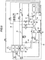
- FIG. 2 is an outline view of an example of a situation to which the present invention is applied, where A shows the case at the time of normal operation and B shows the case where the time for providing cooling steam is long.
- the gas turbine 10 is activated and as the steam turbine that is in a non-ventilated state causes overheating to occur due to windage loss while increasing it's speed, supplying of cooling steam is carried out.
- the steam generating conditions of the exhaust heat recovery boiler 30 fall within a prescribed range in accompaniment with the rising of the output of the gas turbine 10, complete ventilation to the steam turbine 20 is carried out, an output from the steam turbine 20 is obtained and the cooling steam is not required.
- the time until complete ventilation is influenced by the metal temperature conditions etc. of the steam turbine and can be a few minutes or, as in the case of B, a few hours.
Landscapes
- Engineering & Computer Science (AREA)
- Chemical & Material Sciences (AREA)
- Combustion & Propulsion (AREA)
- Mechanical Engineering (AREA)
- General Engineering & Computer Science (AREA)
- Engine Equipment That Uses Special Cycles (AREA)
- Control Of Turbines (AREA)
Priority Applications (1)
| Application Number | Priority Date | Filing Date | Title |
|---|---|---|---|
| EP04004422A EP1455056A1 (de) | 1996-06-26 | 1996-06-26 | Kombikraftwerk in Einwellenanordnung und Verfahren dazu |
Applications Claiming Priority (1)
| Application Number | Priority Date | Filing Date | Title |
|---|---|---|---|
| PCT/JP1996/001762 WO1997049903A1 (en) | 1996-06-26 | 1996-06-26 | Single shaft combined cycle plant and method for operating the same |
Related Child Applications (1)
| Application Number | Title | Priority Date | Filing Date |
|---|---|---|---|
| EP04004422A Division EP1455056A1 (de) | 1996-06-26 | 1996-06-26 | Kombikraftwerk in Einwellenanordnung und Verfahren dazu |
Publications (3)
| Publication Number | Publication Date |
|---|---|
| EP0908603A1 true EP0908603A1 (de) | 1999-04-14 |
| EP0908603A4 EP0908603A4 (de) | 2002-06-05 |
| EP0908603B1 EP0908603B1 (de) | 2004-11-03 |
Family
ID=14153463
Family Applications (1)
| Application Number | Title | Priority Date | Filing Date |
|---|---|---|---|
| EP96921086A Expired - Lifetime EP0908603B1 (de) | 1996-06-26 | 1996-06-26 | Kombikraftwerk in einwellenanordnung |
Country Status (5)
| Country | Link |
|---|---|
| US (1) | US6223518B1 (de) |
| EP (1) | EP0908603B1 (de) |
| JP (1) | JP3694530B2 (de) |
| DE (1) | DE69633794T2 (de) |
| WO (1) | WO1997049903A1 (de) |
Cited By (6)
| Publication number | Priority date | Publication date | Assignee | Title |
|---|---|---|---|---|
| EP2423462A3 (de) * | 2009-05-08 | 2014-01-01 | Kabushiki Kaisha Toshiba | Startverfahren für Einwellen-Kombikraftwerk sowie Einwellen-Kombikraftwerk |
| CN103967544A (zh) * | 2014-05-19 | 2014-08-06 | 山东泓奥电力科技有限公司 | 燃气-蒸汽联合循环发电机组余热利用系统 |
| CN110005487A (zh) * | 2019-04-19 | 2019-07-12 | 上海汽轮机厂有限公司 | 一种蒸汽轮机的启动方法 |
| US11125118B1 (en) | 2020-03-16 | 2021-09-21 | General Electric Company | System and method to improve boiler and steam turbine start-up times |
| US11326471B2 (en) | 2020-03-16 | 2022-05-10 | General Electric Company | System and method to improve boiler and steam turbine start-up times |
| US11927344B2 (en) | 2021-12-23 | 2024-03-12 | General Electric Technology Gmbh | System and method for warmkeeping sub-critical steam generator |
Families Citing this family (15)
| Publication number | Priority date | Publication date | Assignee | Title |
|---|---|---|---|---|
| CA2364125C (en) * | 2000-11-28 | 2005-05-24 | Mitsubishi Heavy Industries, Ltd. | Steam cooling apparatus for gas turbine |
| NL1020350C2 (nl) | 2002-04-10 | 2003-10-13 | Henk Ouwerkerk | Stoom- en gasturbine-inrichting. |
| US7461544B2 (en) * | 2006-02-24 | 2008-12-09 | General Electric Company | Methods for detecting water induction in steam turbines |
| DE102009021924B4 (de) * | 2009-05-19 | 2012-02-23 | Alstom Technology Ltd. | Verfahren zur Primärregelung einer Dampfturbinenanlage |
| WO2010142574A2 (de) * | 2009-06-09 | 2010-12-16 | Siemens Aktiengesellschaft | Anordnung zur verflüssigung von erdgas und verfahren zum anfahren der anordnung |
| US9334753B2 (en) | 2011-10-12 | 2016-05-10 | General Electric Company | Control system and methods for controlling the operation of power generation systems |
| EP2930320A1 (de) * | 2014-04-07 | 2015-10-14 | Siemens Aktiengesellschaft | Verfahren zum Betreiben einer Dampfturbine |
| EP2952702A1 (de) * | 2014-06-04 | 2015-12-09 | Siemens Aktiengesellschaft | Verfahren zum Anwärmen oder Warmhalten einer Dampfturbine |
| US9732635B2 (en) * | 2015-04-29 | 2017-08-15 | General Electric Company | Method for enhanced cold steam turbine start in a supplementary fired multi gas turbine combined cycle plant |
| US10808578B2 (en) | 2015-12-22 | 2020-10-20 | Siemens Aktiengesellschaft | Stack energy control in combined cycle power plant using heating surface bypasses |
| KR101907741B1 (ko) * | 2016-06-27 | 2018-10-12 | 두산중공업 주식회사 | 스팀터빈의 윈디지 로스 방지 장치 |
| AU2018203053B2 (en) | 2017-01-23 | 2020-03-05 | Cephea Valve Technologies, Inc. | Replacement mitral valves |
| CN110030608A (zh) * | 2018-11-22 | 2019-07-19 | 国电电力发展股份有限公司大连开发区热电厂 | 基于高低旁路联合供热模式的热电解耦系统及其方法 |
| JP7249133B2 (ja) | 2018-11-30 | 2023-03-30 | 三菱重工業株式会社 | 蒸気タービン設備及びこれを備えたコンバインドサイクルプラント並びに蒸気タービン設備の改造方法 |
| CN113931745B (zh) * | 2021-09-18 | 2023-06-16 | 华电电力科学研究院有限公司 | 一种燃气蒸汽联合循环机组余热锅炉系统及其启动方法 |
Family Cites Families (9)
| Publication number | Priority date | Publication date | Assignee | Title |
|---|---|---|---|---|
| JPS52143306A (en) * | 1976-05-26 | 1977-11-29 | Hitachi Ltd | Turbine bypass operation method and its system |
| US4571935A (en) * | 1978-10-26 | 1986-02-25 | Rice Ivan G | Process for steam cooling a power turbine |
| JPS62101809A (ja) | 1985-10-29 | 1987-05-12 | Hitachi Ltd | 再熱系を有する一軸コンバインドプラント |
| JP2558740B2 (ja) * | 1987-09-30 | 1996-11-27 | 株式会社東芝 | 二段再熱式蒸気タービンプラントの起動方法 |
| EP0379930B1 (de) * | 1989-01-26 | 1993-05-26 | General Electric Company | Überdrehzahlsicherung für ein Kombikraftwerk mit Gas/Dampf-Turbinen |
| JP3559574B2 (ja) * | 1993-08-27 | 2004-09-02 | 株式会社東芝 | 一軸型コンバインドサイクル発電設備の起動方法 |
| USRE36497E (en) * | 1993-11-04 | 2000-01-18 | General Electric Co. | Combined cycle with steam cooled gas turbine |
| JP3564242B2 (ja) * | 1996-10-29 | 2004-09-08 | 三菱重工業株式会社 | 蒸気冷却ガスタービンの冷却蒸気系統システム |
| JPH10131719A (ja) * | 1996-10-29 | 1998-05-19 | Mitsubishi Heavy Ind Ltd | 蒸気冷却ガスタービンシステム |
-
1996
- 1996-06-26 DE DE69633794T patent/DE69633794T2/de not_active Expired - Lifetime
- 1996-06-26 WO PCT/JP1996/001762 patent/WO1997049903A1/ja active IP Right Grant
- 1996-06-26 EP EP96921086A patent/EP0908603B1/de not_active Expired - Lifetime
- 1996-06-26 US US09/194,723 patent/US6223518B1/en not_active Expired - Lifetime
- 1996-06-26 JP JP50265398A patent/JP3694530B2/ja not_active Expired - Lifetime
Non-Patent Citations (2)
| Title |
|---|
| No further relevant documents disclosed * |
| See also references of WO9749903A1 * |
Cited By (11)
| Publication number | Priority date | Publication date | Assignee | Title |
|---|---|---|---|---|
| EP2423462A3 (de) * | 2009-05-08 | 2014-01-01 | Kabushiki Kaisha Toshiba | Startverfahren für Einwellen-Kombikraftwerk sowie Einwellen-Kombikraftwerk |
| US8739509B2 (en) | 2009-05-08 | 2014-06-03 | Kabushiki Kaisha Toshiba | Single shaft combined cycle power plant start-up method and single shaft combined cycle power plant |
| CN103967544A (zh) * | 2014-05-19 | 2014-08-06 | 山东泓奥电力科技有限公司 | 燃气-蒸汽联合循环发电机组余热利用系统 |
| CN110005487A (zh) * | 2019-04-19 | 2019-07-12 | 上海汽轮机厂有限公司 | 一种蒸汽轮机的启动方法 |
| US11125118B1 (en) | 2020-03-16 | 2021-09-21 | General Electric Company | System and method to improve boiler and steam turbine start-up times |
| WO2021188309A1 (en) * | 2020-03-16 | 2021-09-23 | General Electric Company | System and method to improve boiler and steam turbine start-up times |
| CN113874603A (zh) * | 2020-03-16 | 2021-12-31 | 通用电气公司 | 用于改进锅炉和蒸汽涡轮机启动时间的系统和方法 |
| US11326471B2 (en) | 2020-03-16 | 2022-05-10 | General Electric Company | System and method to improve boiler and steam turbine start-up times |
| JP2023519036A (ja) * | 2020-03-16 | 2023-05-10 | ゼネラル・エレクトリック・カンパニイ | ボイラおよび蒸気タービンの始動時間を改善するためのシステムおよび方法 |
| CN113874603B (zh) * | 2020-03-16 | 2023-10-13 | 通用电气公司 | 用于改进锅炉和蒸汽涡轮机启动时间的系统和方法 |
| US11927344B2 (en) | 2021-12-23 | 2024-03-12 | General Electric Technology Gmbh | System and method for warmkeeping sub-critical steam generator |
Also Published As
| Publication number | Publication date |
|---|---|
| EP0908603B1 (de) | 2004-11-03 |
| WO1997049903A1 (en) | 1997-12-31 |
| US6223518B1 (en) | 2001-05-01 |
| DE69633794T2 (de) | 2005-10-27 |
| EP0908603A4 (de) | 2002-06-05 |
| JP3694530B2 (ja) | 2005-09-14 |
| DE69633794D1 (de) | 2004-12-09 |
Similar Documents
| Publication | Publication Date | Title |
|---|---|---|
| US6223518B1 (en) | Single shaft combined cycle plant and method for operating the same | |
| US6405537B1 (en) | Single shaft combined cycle plant and operating thereof | |
| US6339926B1 (en) | Steam-cooled gas turbine combined power plant | |
| US4519207A (en) | Combined plant having steam turbine and gas turbine connected by single shaft | |
| US6220014B1 (en) | Single shaft combined cycle plant and operating method thereof | |
| JP2680033B2 (ja) | コンバインドプラントの運転方法及び装置 | |
| US20140165565A1 (en) | Steam turbine plant and driving method thereof | |
| JPH1193694A (ja) | ガスタービンプラント | |
| JPS61107004A (ja) | 複合サイクル発電ブラントのための熱回収蒸気発生器出口温度制御装置 | |
| JP2000161014A5 (de) | ||
| JPH0353443B2 (de) | ||
| US5435138A (en) | Reduction in turbine/boiler thermal stress during bypass operation | |
| JPH09112215A (ja) | ガスタービンプラントおよびその運転方法 | |
| JPH02230905A (ja) | ガスタービン・蒸気タービン組合せサイクルの超過速度防護装置 | |
| JP2523518B2 (ja) | 高圧タ―ビン起動による蒸気タ―ビンプラントの起動方法 | |
| JP3919966B2 (ja) | コンバインドサイクル発電プラントの運転方法 | |
| EP1455056A1 (de) | Kombikraftwerk in Einwellenanordnung und Verfahren dazu | |
| JP3660727B2 (ja) | 一軸型コンバインドサイクルプラントの運転方法 | |
| EP1273768B1 (de) | Verfahren zum Betrieb eines Kombikraftwerks | |
| JPS5926765B2 (ja) | タ−ビンバイパスラインを有するタ−ビンプラントの制御方法およびその装置 | |
| JPH10131721A (ja) | ガスタービン蒸気系統 | |
| JP2001090507A (ja) | 発電プラント | |
| JPH0336123B2 (de) | ||
| JP2003343213A (ja) | クローズド蒸気冷却ガスタービンコンバインドプラント | |
| JPH0968004A (ja) | コンバインドサイクル発電プラントの安全弁作動テスト方法 |
Legal Events
| Date | Code | Title | Description |
|---|---|---|---|
| PUAI | Public reference made under article 153(3) epc to a published international application that has entered the european phase |
Free format text: ORIGINAL CODE: 0009012 |
|
| 17P | Request for examination filed |
Effective date: 19981221 |
|
| AK | Designated contracting states |
Kind code of ref document: A1 Designated state(s): DE FR GB |
|
| A4 | Supplementary search report drawn up and despatched |
Effective date: 20020419 |
|
| AK | Designated contracting states |
Kind code of ref document: A4 Designated state(s): DE FR GB |
|
| 17Q | First examination report despatched |
Effective date: 20030626 |
|
| GRAP | Despatch of communication of intention to grant a patent |
Free format text: ORIGINAL CODE: EPIDOSNIGR1 |
|
| RTI1 | Title (correction) |
Free format text: SINGLE SHAFT COMBINED CYCLE PLANT |
|
| GRAS | Grant fee paid |
Free format text: ORIGINAL CODE: EPIDOSNIGR3 |
|
| GRAA | (expected) grant |
Free format text: ORIGINAL CODE: 0009210 |
|
| AK | Designated contracting states |
Kind code of ref document: B1 Designated state(s): DE FR GB |
|
| REG | Reference to a national code |
Ref country code: GB Ref legal event code: FG4D |
|
| REF | Corresponds to: |
Ref document number: 69633794 Country of ref document: DE Date of ref document: 20041209 Kind code of ref document: P |
|
| PLBE | No opposition filed within time limit |
Free format text: ORIGINAL CODE: 0009261 |
|
| STAA | Information on the status of an ep patent application or granted ep patent |
Free format text: STATUS: NO OPPOSITION FILED WITHIN TIME LIMIT |
|
| ET | Fr: translation filed | ||
| 26N | No opposition filed |
Effective date: 20050804 |
|
| REG | Reference to a national code |
Ref country code: FR Ref legal event code: TP Owner name: MITSUBISHI HITACHI POWER SYSTEMS, LTD., JP Effective date: 20141124 |
|
| REG | Reference to a national code |
Ref country code: DE Ref legal event code: R082 Ref document number: 69633794 Country of ref document: DE Representative=s name: V. FUENER EBBINGHAUS FINCK HANO, DE |
|
| REG | Reference to a national code |
Ref country code: DE Ref legal event code: R082 Ref document number: 69633794 Country of ref document: DE Representative=s name: V. FUENER EBBINGHAUS FINCK HANO, DE Effective date: 20150211 Ref country code: DE Ref legal event code: R081 Ref document number: 69633794 Country of ref document: DE Owner name: MITSUBISHI HITACHI POWER SYSTEMS, LTD., YOKOHA, JP Free format text: FORMER OWNER: HITACHI, LTD., TOKYO, JP Effective date: 20150211 |
|
| REG | Reference to a national code |
Ref country code: FR Ref legal event code: PLFP Year of fee payment: 20 |
|
| REG | Reference to a national code |
Ref country code: GB Ref legal event code: 732E Free format text: REGISTERED BETWEEN 20150528 AND 20150603 |
|
| PGFP | Annual fee paid to national office [announced via postgrant information from national office to epo] |
Ref country code: DE Payment date: 20150624 Year of fee payment: 20 Ref country code: GB Payment date: 20150624 Year of fee payment: 20 |
|
| PGFP | Annual fee paid to national office [announced via postgrant information from national office to epo] |
Ref country code: FR Payment date: 20150608 Year of fee payment: 20 |
|
| REG | Reference to a national code |
Ref country code: DE Ref legal event code: R071 Ref document number: 69633794 Country of ref document: DE |
|
| REG | Reference to a national code |
Ref country code: GB Ref legal event code: PE20 Expiry date: 20160625 |
|
| PG25 | Lapsed in a contracting state [announced via postgrant information from national office to epo] |
Ref country code: GB Free format text: LAPSE BECAUSE OF EXPIRATION OF PROTECTION Effective date: 20160625 |