EP2994348B1 - Beleuchtungseinrichtung für kraftfahrzeuge - Google Patents
Beleuchtungseinrichtung für kraftfahrzeuge Download PDFInfo
- Publication number
- EP2994348B1 EP2994348B1 EP14726505.2A EP14726505A EP2994348B1 EP 2994348 B1 EP2994348 B1 EP 2994348B1 EP 14726505 A EP14726505 A EP 14726505A EP 2994348 B1 EP2994348 B1 EP 2994348B1
- Authority
- EP
- European Patent Office
- Prior art keywords
- light
- light guide
- lighting device
- guide element
- designed
- Prior art date
- Legal status (The legal status is an assumption and is not a legal conclusion. Google has not performed a legal analysis and makes no representation as to the accuracy of the status listed.)
- Active
Links
Images

Classifications
-
- B—PERFORMING OPERATIONS; TRANSPORTING
- B60—VEHICLES IN GENERAL
- B60Q—ARRANGEMENT OF SIGNALLING OR LIGHTING DEVICES, THE MOUNTING OR SUPPORTING THEREOF OR CIRCUITS THEREFOR, FOR VEHICLES IN GENERAL
- B60Q1/00—Arrangement of optical signalling or lighting devices, the mounting or supporting thereof or circuits therefor
- B60Q1/0029—Spatial arrangement
- B60Q1/0041—Spatial arrangement of several lamps in relation to each other
-
- B—PERFORMING OPERATIONS; TRANSPORTING
- B60—VEHICLES IN GENERAL
- B60Q—ARRANGEMENT OF SIGNALLING OR LIGHTING DEVICES, THE MOUNTING OR SUPPORTING THEREOF OR CIRCUITS THEREFOR, FOR VEHICLES IN GENERAL
- B60Q1/00—Arrangement of optical signalling or lighting devices, the mounting or supporting thereof or circuits therefor
- B60Q1/0011—Arrangement of optical signalling or lighting devices, the mounting or supporting thereof or circuits therefor with light guides for distributing the light between several lighting or signalling devices
-
- B—PERFORMING OPERATIONS; TRANSPORTING
- B60—VEHICLES IN GENERAL
- B60Q—ARRANGEMENT OF SIGNALLING OR LIGHTING DEVICES, THE MOUNTING OR SUPPORTING THEREOF OR CIRCUITS THEREFOR, FOR VEHICLES IN GENERAL
- B60Q1/00—Arrangement of optical signalling or lighting devices, the mounting or supporting thereof or circuits therefor
- B60Q1/02—Arrangement of optical signalling or lighting devices, the mounting or supporting thereof or circuits therefor the devices being primarily intended to illuminate the way ahead or to illuminate other areas of way or environments
- B60Q1/04—Arrangement of optical signalling or lighting devices, the mounting or supporting thereof or circuits therefor the devices being primarily intended to illuminate the way ahead or to illuminate other areas of way or environments the devices being headlights
-
- F—MECHANICAL ENGINEERING; LIGHTING; HEATING; WEAPONS; BLASTING
- F21—LIGHTING
- F21S—NON-PORTABLE LIGHTING DEVICES; SYSTEMS THEREOF; VEHICLE LIGHTING DEVICES SPECIALLY ADAPTED FOR VEHICLE EXTERIORS
- F21S41/00—Illuminating devices specially adapted for vehicle exteriors, e.g. headlamps
- F21S41/10—Illuminating devices specially adapted for vehicle exteriors, e.g. headlamps characterised by the light source
- F21S41/14—Illuminating devices specially adapted for vehicle exteriors, e.g. headlamps characterised by the light source characterised by the type of light source
- F21S41/141—Light emitting diodes [LED]
- F21S41/151—Light emitting diodes [LED] arranged in one or more lines
-
- F—MECHANICAL ENGINEERING; LIGHTING; HEATING; WEAPONS; BLASTING
- F21—LIGHTING
- F21S—NON-PORTABLE LIGHTING DEVICES; SYSTEMS THEREOF; VEHICLE LIGHTING DEVICES SPECIALLY ADAPTED FOR VEHICLE EXTERIORS
- F21S41/00—Illuminating devices specially adapted for vehicle exteriors, e.g. headlamps
- F21S41/10—Illuminating devices specially adapted for vehicle exteriors, e.g. headlamps characterised by the light source
- F21S41/14—Illuminating devices specially adapted for vehicle exteriors, e.g. headlamps characterised by the light source characterised by the type of light source
- F21S41/141—Light emitting diodes [LED]
- F21S41/155—Surface emitters, e.g. organic light emitting diodes [OLED]
-
- F—MECHANICAL ENGINEERING; LIGHTING; HEATING; WEAPONS; BLASTING
- F21—LIGHTING
- F21S—NON-PORTABLE LIGHTING DEVICES; SYSTEMS THEREOF; VEHICLE LIGHTING DEVICES SPECIALLY ADAPTED FOR VEHICLE EXTERIORS
- F21S41/00—Illuminating devices specially adapted for vehicle exteriors, e.g. headlamps
- F21S41/20—Illuminating devices specially adapted for vehicle exteriors, e.g. headlamps characterised by refractors, transparent cover plates, light guides or filters
- F21S41/24—Light guides
-
- F—MECHANICAL ENGINEERING; LIGHTING; HEATING; WEAPONS; BLASTING
- F21—LIGHTING
- F21S—NON-PORTABLE LIGHTING DEVICES; SYSTEMS THEREOF; VEHICLE LIGHTING DEVICES SPECIALLY ADAPTED FOR VEHICLE EXTERIORS
- F21S43/00—Signalling devices specially adapted for vehicle exteriors, e.g. brake lamps, direction indicator lights or reversing lights
- F21S43/10—Signalling devices specially adapted for vehicle exteriors, e.g. brake lamps, direction indicator lights or reversing lights characterised by the light source
- F21S43/13—Signalling devices specially adapted for vehicle exteriors, e.g. brake lamps, direction indicator lights or reversing lights characterised by the light source characterised by the type of light source
- F21S43/14—Light emitting diodes [LED]
-
- F—MECHANICAL ENGINEERING; LIGHTING; HEATING; WEAPONS; BLASTING
- F21—LIGHTING
- F21S—NON-PORTABLE LIGHTING DEVICES; SYSTEMS THEREOF; VEHICLE LIGHTING DEVICES SPECIALLY ADAPTED FOR VEHICLE EXTERIORS
- F21S43/00—Signalling devices specially adapted for vehicle exteriors, e.g. brake lamps, direction indicator lights or reversing lights
- F21S43/10—Signalling devices specially adapted for vehicle exteriors, e.g. brake lamps, direction indicator lights or reversing lights characterised by the light source
- F21S43/13—Signalling devices specially adapted for vehicle exteriors, e.g. brake lamps, direction indicator lights or reversing lights characterised by the light source characterised by the type of light source
- F21S43/14—Light emitting diodes [LED]
- F21S43/145—Surface emitters, e.g. organic light emitting diodes [OLED]
-
- F—MECHANICAL ENGINEERING; LIGHTING; HEATING; WEAPONS; BLASTING
- F21—LIGHTING
- F21S—NON-PORTABLE LIGHTING DEVICES; SYSTEMS THEREOF; VEHICLE LIGHTING DEVICES SPECIALLY ADAPTED FOR VEHICLE EXTERIORS
- F21S43/00—Signalling devices specially adapted for vehicle exteriors, e.g. brake lamps, direction indicator lights or reversing lights
- F21S43/20—Signalling devices specially adapted for vehicle exteriors, e.g. brake lamps, direction indicator lights or reversing lights characterised by refractors, transparent cover plates, light guides or filters
- F21S43/235—Light guides
- F21S43/236—Light guides characterised by the shape of the light guide
- F21S43/239—Light guides characterised by the shape of the light guide plate-shaped
-
- F—MECHANICAL ENGINEERING; LIGHTING; HEATING; WEAPONS; BLASTING
- F21—LIGHTING
- F21S—NON-PORTABLE LIGHTING DEVICES; SYSTEMS THEREOF; VEHICLE LIGHTING DEVICES SPECIALLY ADAPTED FOR VEHICLE EXTERIORS
- F21S43/00—Signalling devices specially adapted for vehicle exteriors, e.g. brake lamps, direction indicator lights or reversing lights
- F21S43/20—Signalling devices specially adapted for vehicle exteriors, e.g. brake lamps, direction indicator lights or reversing lights characterised by refractors, transparent cover plates, light guides or filters
- F21S43/235—Light guides
- F21S43/242—Light guides characterised by the emission area
- F21S43/243—Light guides characterised by the emission area emitting light from one or more of its extremities
-
- F—MECHANICAL ENGINEERING; LIGHTING; HEATING; WEAPONS; BLASTING
- F21—LIGHTING
- F21S—NON-PORTABLE LIGHTING DEVICES; SYSTEMS THEREOF; VEHICLE LIGHTING DEVICES SPECIALLY ADAPTED FOR VEHICLE EXTERIORS
- F21S43/00—Signalling devices specially adapted for vehicle exteriors, e.g. brake lamps, direction indicator lights or reversing lights
- F21S43/20—Signalling devices specially adapted for vehicle exteriors, e.g. brake lamps, direction indicator lights or reversing lights characterised by refractors, transparent cover plates, light guides or filters
- F21S43/235—Light guides
- F21S43/249—Light guides with two or more light sources being coupled into the light guide
-
- F—MECHANICAL ENGINEERING; LIGHTING; HEATING; WEAPONS; BLASTING
- F21—LIGHTING
- F21S—NON-PORTABLE LIGHTING DEVICES; SYSTEMS THEREOF; VEHICLE LIGHTING DEVICES SPECIALLY ADAPTED FOR VEHICLE EXTERIORS
- F21S43/00—Signalling devices specially adapted for vehicle exteriors, e.g. brake lamps, direction indicator lights or reversing lights
- F21S43/20—Signalling devices specially adapted for vehicle exteriors, e.g. brake lamps, direction indicator lights or reversing lights characterised by refractors, transparent cover plates, light guides or filters
- F21S43/235—Light guides
- F21S43/251—Light guides the light guides being used to transmit light from remote light sources
-
- B—PERFORMING OPERATIONS; TRANSPORTING
- B60—VEHICLES IN GENERAL
- B60Q—ARRANGEMENT OF SIGNALLING OR LIGHTING DEVICES, THE MOUNTING OR SUPPORTING THEREOF OR CIRCUITS THEREFOR, FOR VEHICLES IN GENERAL
- B60Q1/00—Arrangement of optical signalling or lighting devices, the mounting or supporting thereof or circuits therefor
- B60Q1/0029—Spatial arrangement
- B60Q1/0041—Spatial arrangement of several lamps in relation to each other
- B60Q1/0052—Spatial arrangement of several lamps in relation to each other concentric
-
- F—MECHANICAL ENGINEERING; LIGHTING; HEATING; WEAPONS; BLASTING
- F21—LIGHTING
- F21S—NON-PORTABLE LIGHTING DEVICES; SYSTEMS THEREOF; VEHICLE LIGHTING DEVICES SPECIALLY ADAPTED FOR VEHICLE EXTERIORS
- F21S43/00—Signalling devices specially adapted for vehicle exteriors, e.g. brake lamps, direction indicator lights or reversing lights
- F21S43/20—Signalling devices specially adapted for vehicle exteriors, e.g. brake lamps, direction indicator lights or reversing lights characterised by refractors, transparent cover plates, light guides or filters
- F21S43/235—Light guides
-
- F—MECHANICAL ENGINEERING; LIGHTING; HEATING; WEAPONS; BLASTING
- F21—LIGHTING
- F21Y—INDEXING SCHEME ASSOCIATED WITH SUBCLASSES F21K, F21L, F21S and F21V, RELATING TO THE FORM OR THE KIND OF THE LIGHT SOURCES OR OF THE COLOUR OF THE LIGHT EMITTED
- F21Y2105/00—Planar light sources
-
- F—MECHANICAL ENGINEERING; LIGHTING; HEATING; WEAPONS; BLASTING
- F21—LIGHTING
- F21Y—INDEXING SCHEME ASSOCIATED WITH SUBCLASSES F21K, F21L, F21S and F21V, RELATING TO THE FORM OR THE KIND OF THE LIGHT SOURCES OR OF THE COLOUR OF THE LIGHT EMITTED
- F21Y2115/00—Light-generating elements of semiconductor light sources
- F21Y2115/20—Electroluminescent [EL] light sources
Definitions
- the invention relates to a lighting device for motor vehicles with a light guide element which has a light entry surface and a light exit surface, a light guide being provided which has at least one feed point for light from at least one light source, the light guide being rod-shaped and along at least part of it Length has an impurity arrangement and a light exit surface opposite this and the light entry surface of the light guide element connects to the light exit surface of the rod-shaped light guide in terms of light technology.
- Lighting devices of this type are widely used nowadays in the motor vehicle sector, for example such light guide elements are arranged around the exit openings of headlights, with light originating from light emitting diodes, for example, being radiated into the light entry surface and radiated forward.
- motifs of the design are often essential for the configuration and geometry of such light guide elements.
- lighting devices are also arranged for interior lighting or on the side or at the rear of motor vehicles. Solutions are known in which side surfaces of the light guide element are provided with an impurity structure so that the light radiated into the light entry surface is scattered at the impurities and also emitted laterally.
- a lighting device of this type is for example in the DE 10 2010 054 923 A1 shown in connection with a headlight, whereas the DE 10 2011 050 422 A1 discloses a similar application in a rear light of a motor vehicle.
- EP 2 541 128 A2 discloses a generic lighting device for motor vehicles.
- One object of the invention is to create a lighting device of the type in question which enables light to be emitted not only from the light exit surface but also from the side.
- no complex structuring of the light guide element should be necessary and, on the other hand, a high degree of flexibility with regard to the quality of the emitted light (intensity, color) should be possible.
- an electrical luminous layer which is designed to be translucent, is provided at least partially on at least one surface of the light guide element, with the exception of the light entry surface.
- Such luminous layers which can be designed as so-called “OLED” layers, for example, enable illumination in different colors and are problem-free in terms of production technology insofar as they can be produced very thin.
- the luminous layer is designed as an OLED layer, but it is also possible to design the luminous layer, for example, as an electroluminescent layer.
- a rod-shaped light guide which has at least one feed point for light from at least one light source, the light guide has an impurity arrangement along at least part of its length and a light exit surface opposite this, and the light entry surface of the light guide element connects to the light exit surface of the rod-shaped light guide in terms of light technology.
- the use of such a system which is well known in lighting technology for motor vehicles (e.g. AT 503 926 B1 ) rod-shaped light guide results in good illumination, which can also come from just a single light source located at the feed point, with light-emitting diodes being particularly suitable as light sources.
- the light guide element is designed as a hollow cylinder, the two end surfaces of the cylinder wall forming the light entry and light exit surfaces.
- Such a geometry can be used flexibly, for example, in connection with front lights in motor vehicles.
- the The cylinder wall surrounds the light exit opening of a headlight module at least in sections.
- the geometry of the rod-shaped light guide is adapted to the light entry surface of the light guide element in order to avoid light losses and to simplify the construction.
- the light guide element consists of a transparent material. This results in low light losses and unnecessary heating of the light guide element is avoided. However, this does not mean that in certain cases the requirement for transparency can be abandoned and an opaque material can be used if special lighting effects are desired.
- the light guide element is designed as a hollow cylinder, it is aesthetically particularly satisfactory in many cases if an electrical luminous layer is provided on the outer surfaces of the hollow cylinder.
- a cuboid light guide element 1 which is advantageously formed from a completely transparent material, in particular from plastic, and which has a light entry surface 2 and a light exit surface 3.
- the light guide element 1 which could also be referred to as thick-walled optics, is assigned a rod-shaped light guide 4, which has a feed point for light, here an end face 5, on which an LED element 6 is provided as a light source in the present case.
- the light guide 4 here has an impurity arrangement 7 on a flat lower surface and opposite this has a light exit surface 8 which, in the present case, is approximately cylindrical, but could just as easily be flat or have a different shape.
- Light guides of this type are known, the light fed in by the light source 6, here an LED element, being reflected along the light guide 4 and emitted outwards by the impurity arrangement 7, for example an array of small prisms, via the light exit surface 8.
- the light emerging from the light exit surface 8 enters the entry surface 2 of the cuboid light guide element 1 and mainly exits at the opposite light exit surface 3 for lighting purposes, the arrangement being able to be used, for example, for position lights in a motor vehicle.
- both the light guide 4 and the light guide element 1 are straight, but it should be clear that the light guide can be curved as desired, with an adaptation of the curvature between the light guide element 1 and the light guide 4 in general.
- the light can also be fed into the light guide 4 not only at a single position, as here at the end face 5, but for example at both end faces of the light guide or additionally at branches opening into the light guide.
- An electrical luminous layer 9 is only applied to one side surface, here the one on the right in the picture.
- a luminous layer is advantageously designed as an OLED layer.
- This is understood to be an organic light-emitting diode which is a luminous thin-film component made of organic semiconducting materials and which, depending on its composition, can glow in different colors when a voltage is applied.
- the OLED layer can also be transparent, thus translucent.
- side surfaces of the light guide element can be provided with similar or different luminous layers, the choice of color and / or intensity of the light emitted by the respective luminous layers being adapted to the corresponding requirements.
- Electroluminescent films are commercially available and emit light when an alternating voltage is applied. They can also be made transparent.
- Fig. 2 Figure 8 again shows a lighting device not forming part of the invention that follows that after Fig. 1 in that it also has a cuboid light guide element 1 with a light entry surface 2 and a light exit surface 3.
- an electrical luminous layer 9 is formed on the left longitudinal surface of the light guide element 1 in the figure and it is indicated that a further electrical luminous layer 10 can also be provided on the light exit surface 3, in which case it must be designed to be translucent.
- Fig. 1 In contrast to Fig. 1
- three individual LED elements 11 are arranged as light sources on the light entry surface 2 of the light guide element 1, the light of which the light guide element 1 interspersed and exits at the light exit surface 3 for lighting purposes.
- some of the light fed in at the light entry surface 2 can also exit on side surfaces.
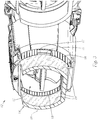
- Fig. 3 shows a more complex design of a lighting device according to the invention in combination with a headlight module 12.
- This headlight module 12 can be used, for example, to generate a conventional low beam and has a light exit opening 13.
- This opening 13 is surrounded over most of its circumference by a light guide element 14, which is designed as a hollow cylinder with a flat, forward-facing light exit surface 15.
- the term “forward” is of course to be understood in the sense of light emission and does not necessarily mean “in the direction of travel of a vehicle”.
- the light guide element 14 Opposite the light exit surface 15, the light guide element 14 has a light entry surface 16 into which light from a light guide 17 is fed.
- This light guide 17 corresponds in its geometry to the design of the light guide element 14, that is, it also surrounds the light exit opening 13 of the headlight module 12 and it can in principle be designed similar to that in FIG Fig. 1 shown light guide 4, but is curved in contrast to this.
- the light can be fed in, which cannot be seen in the drawing, at the two ends of the light guide 17, for example by means of LED elements. Only a small section of the light guide 17 is shown in FIG Fig. 3 to see, since this light guide is covered by a circumferential screen 18 in the embodiment shown.
- the inner and outer surfaces of the hollow-cylindrical light guide element 14 are provided with electrical luminous layers 19.
- the headlight module 12 equipped with a lighting device according to the invention thus has at least three light functions, namely, for example, the aforementioned low beam function, which originates from the headlight module as such and from a light source, not shown, arranged inside the module 12, which is radiated forward through the light guide element 14 Light from the light guide 17 and, thirdly, the light originating from the electrical luminous layers 19. It goes without saying that in addition to the purely technical light functions, thanks to the invention, special aesthetic effects can also be achieved that meet the corresponding design specifications.
- the drawings do not show the electrical connection means required for supplying power to the individual light sources, nor their current and / or voltage sources, but relevant information is available to those skilled in the art for implementation.
- the electrical luminous layers for example OLED layers
- OLED layers by no means have to be formed over the entire area, but can in certain cases also be formed as strips or other structures.
- the use of electrical luminous layers in the lighting device according to the invention also offers the particular advantage that there is virtually no restriction with regard to the geometry of the light guide element.
- the surfaces to which the luminous layers are adapted are de facto freely definable and, of course, do not have to be flat, which is evident from the exemplary embodiment in FIG Fig. 3 emerges.
Landscapes
- Engineering & Computer Science (AREA)
- General Engineering & Computer Science (AREA)
- Physics & Mathematics (AREA)
- Microelectronics & Electronic Packaging (AREA)
- Optics & Photonics (AREA)
- Mechanical Engineering (AREA)
- Non-Portable Lighting Devices Or Systems Thereof (AREA)
Description
- Die Erfindung bezieht sich auf eine Beleuchtungseinrichtung für Kraftfahrzeuge mit einem Lichtleitelement, welches eine Lichteintrittsfläche und eine Lichtaustrittsfläche aufweist, wobei ein Lichtleiter vorgesehen ist, der zumindest eine Einspeisestelle für Licht zumindest einer Lichtquelle aufweist, wobei der Lichtleiter stabförmig ausgebildet ist und entlang zumindest eines Teils seiner Länge eine Störstellenanordnung sowie eine dieser gegenüberliegende Lichtaustrittsfläche aufweist und die Lichteintrittsfläche des Lichtleitelements lichttechnisch an die Lichtaustritts fläche des stabförmigen Lichtleiters anschließt.
- Beleuchtungseinrichtungen dieser Art werden heutzutage im Kraftfahrzeugbereich vielfach verwendet, beispielsweise finden sich solche Lichtleitelemente um die Austrittsöffnungen von Scheinwerfern herum angeordnet, wobei beispielsweise von Leuchtdioden stammendes Licht in die Lichteintrittsfläche eingestrahlt und nach vorne abgestrahlt wird. Neben der eigentlichen Beleuchtungsfunktion sind vielfach auch Motive des Designs für die Ausgestaltung und die Geometrie derartiger Lichtleitelemente wesentlich. Neben der Verwendung im Bereich von Frontscheinwerfern werden solche Beleuchtungseinrichtungen auch für eine Innenraumbeleuchtung oder seitlich bzw. am Heck von Kraftfahrzeugen angeordnet. Es sind Lösungen bekannt, bei welchen Seitenflächen des Lichtleitelementes mit einer Störstellen-Strukturierung versehen sind, sodass dass das in die Lichteintrittsfläche eingestrahlte Licht an den Störstellen gestreut und auch seitlich abgestrahlt wird.
- Eine Beleuchtungseinrichtung dieser Art ist beispielsweise in der
DE 10 2010 054 923 A1 im Zusammenhang mit einem Frontscheinwerfer gezeigt, wogegen dieDE 10 2011 050 422 A1 eine ähnliche Anwendung bei einer Heckleuchte eines Kraftfahrzeuges offenbart. -
EP 2 541 128 A2 offenbart eine gattungsgemäße Beleuchtungseinrichtung für Kraftfahrzeuge. - Eine Aufgabe der Erfindung liegt in der Schaffung einer Beleuchtungseinrichtung der gegenständlichen Art, welche eine Lichtabstrahlung nicht nur aus der Lichtaustrittsfläche sondern auch seitlich ermöglicht. Dabei sollen einerseits keine aufwändigen Strukturierungen des Lichtleitelementes erforderlich sein und andererseits soll eine hohe Flexibilität hinsichtlich der Qualität des abgestrahlten Lichtes (Intensität, Farbe) möglich sein.
- Zur Lösung dieser Aufgabe sieht die Erfindung vor, dass zumindest teilweise an zumindest einer Oberfläche des Lichtleitelementes, ausgenommen die Lichteintrittsfläche, eine elektrische Leuchtschicht vorgesehen ist, welche durchscheinend ausgebildet ist.
- Tatsächlich lassen sich bei einer erfindungsgemäßen Beleuchtungseinrichtung für einen Betrachter auf einfache Weise Tiefeneindrücke bzw. 3-D Effekte erzielen, für welche nach dem Stand der Technik aufwändige Lichtleiterkombinationen und -strukturen erforderlich waren. Auch können bei für einen Betrachter scheinbar gleicher Geometrie mehrere Lichtfunktionen realisiert werden.
- Derartige Leuchtschichten, die beispielsweise als so genannte "OLED"-Schichten ausgebildet sein können, ermöglichen eine Beleuchtung in unterschiedlichen Farben und sind fertigungstechnisch insofern problemlos, als sie sehr dünn hergestellt werden können.
- An dieser Stelle ist zu erwähnen, dass die Verwendung von OLED-Schichten im Zusammenhang mit Kraftfahrzeugbeleuchtungen aus der
DE 10 2009 009 087 A1 bekannt geworden ist, wobei in diesem Dokument eine Beleuchtungseinrichtung für ein Kraftfahrzeug gezeigt ist, bei welcher vor einem Reflektor für eine erste Lichtquelle eine den Reflektor abdeckende dünne, flächige organische Leuchtdiode (OLED) angeordnet ist, wodurch beispielsweise die Lichtfunktionen einer Nebelschlussleuchte und eines Schlusslichtes überlagert werden können. - Wie bereits erwähnt ist bei einer vorteilhaften Ausführungsform vorgesehen, dass die Leuchtschicht als OLED-Schicht ausgebildet ist, doch ist es auch möglich, die Leuchtschicht beispielsweise als Elektrolumineszenz-Schicht auszubilden.
- Gemäß der Erfindung ist ein stabförmiger Lichtleiter vorgesehen, der zumindest eine Einspeisestelle für Licht zumindest einer Lichtquelle aufweist, der Lichtleiter entlang zumindest eines Teiles seiner Länge eine Störstellenanordnung sowie eine dieser gegenüberliegende Lichtaustrittsfläche aufweist und die Lichteintrittsfläche des Lichtleitelementes lichttechnisch an die Lichtaustrittsfläche des stabförmigen Lichtleiters anschließt. Die Verwendung eines solchen, in der Beleuchtungstechnik für Kraftfahrzeuge bestens bekannten (z.B.
AT 503 926 B1 - Weiters kann vorgesehen sein, dass das Lichtleitelement als Hohlzylinder ausgebildet ist, wobei die beiden Endflächen der Zylinderwand die Lichteintritts- und die Lichtsaustrittsfläche bilden. Eine derartige Geometrie ist beispielsweise im Zusammenhang mit Frontleuchten bei Kraftfahrzeugen flexibel einzusetzen. Insbesondere kann vorgesehen sein, dass die Zylinderwand zumindest abschnittsweise die Lichtaustrittsöffnung eines Scheinwerfermoduls umgibt.
- Es ist weiters zweckmäßig, wenn der stabförmige Lichtleiter in seiner Geometrie der Lichteintrittsfläche des Lichtleitelementes angepasst ist, um Lichtverluste zu vermeiden und um die Konstruktion zu vereinfachen.
- Im Allgemeinen ist es vorzuziehen, wenn das Lichtleitelement aus einem transparenten Material besteht. Auf diese Weise ergeben sich geringe Lichtverluste und eine unnötige Erwärmung des Lichtleitelementes wird vermieden. Dies bedeutet jedoch nicht, dass in gewissen Fällen von der Forderung nach Transparenz abgegangen und ein opakes Material verwendet werden kann, wenn besondere Lichteffekte gewünscht sind.
- Insbesondere bei Ausbildung des Lichtleitelementes als Hohlzylinder ist es in vielen Fällen ästhetisch besonders zufriedenstellend, wenn eine elektrische Leuchtschicht an Außenflächen des Hohlzylinders vorgesehen ist.
- Andere ästhetische Eindrücke ergeben sich, weil die elektrische Leuchtschicht durchscheinend ausgebildet ist.
- Die Erfindung samt weiteren Vorteilen ist im Folgenden anhand beispielsweise Ausführungsformen näher erläutert, die in der Zeichnung dargestellt sind. In dieser zeigen
-
Fig. 1 den prinzipiellen Aufbau einer Beleuchtungseinrichtung nach der Erfindung zusammen mit einem stabförmigen Lichtleiter in teilweiser und perspektivischer Ansicht, -
Fig. 2 eine Variante, die nicht ein Teil der Erfindung ist, bei welcher anstelle eines stabförmigen Lichtleiters einzelne Lichtquellen vorgesehen sind und -
Fig. 3 eine Variante, bei welcher das Lichtleitelement in Form eines Hohlzylinders ausgebildet ist und die Lichtaustrittsfläche eines Scheinwerfermoduls umgibt, gleichfalls im teilweiser und perspektivischer Darstellung. - Unter Bezugnahme auf
Fig. 1 erkennt man ein quaderförmiges Lichtleitelement 1, welches vorteilhafterweise aus einem vollständig transparenten Material, insbesondere aus Kunststoff, ausgebildet ist und welches eine Lichteintrittsfläche 2 sowie eine Lichtaustrittsfläche 3 besitzt. Dem Lichtleitelement 1, das auch als Dickwandoptik bezeichnet werden könnte, ist ein stabförmiger Lichtleiter 4 zugeordnet, der eine Einspeisestelle für Licht aufweist, hier eine Stirnfläche 5, an der im vorliegenden Fall als Lichtquelle ein LED-Element 6 vorgesehen ist. Der Lichtleiter 4 besitzt hier an einer ebenen unteren Fläche eine Störstellenanordnung 7 und weist diese gegenüberliegend eine Lichtaustrittsfläche 8 auf, die im vorliegenden Fall etwa zylindrisch ausgebildet ist, jedoch ebenso gut eben sein oder eine andere Form aufweisen könnte. Lichtleiter dieser Art sind bekannt, wobei das von der Lichtquelle 6, hier einem LED-Element, eingespeiste Licht längs des Lichtleiters 4 reflektiert und von der Störstellenanordnung 7, z.B. ein Array von kleinen Prismen, über die Lichtaustrittsfläche 8 nach außen abgestrahlt wird. - Es ist ersichtlich, dass das von der Lichtsaustrittsfläche 8 austretende Licht in die Eintrittsfläche 2 des quaderförmigen Lichtleitelementes 1 eintritt und hauptsächlich an der gegenüberliegenden Lichtaustrittsfläche 3 zu Beleuchtungszwecken austritt, wobei die Anordnung beispielsweise für Positionsleuchten in einem Kraftfahrzeug verwendet werden kann. In dem Beispiel nach
Fig. 1 sind zur Vereinfachung sowohl der Lichtleiter 4 als auch das Lichtleitelement 1 geradlinig ausgebildet, doch soll es klar sein, dass der Lichtleiter beliebig gekrümmt sein kann, wobei eine Anpassung der Krümmung zwischen dem Lichtleitelement 1 und dem Lichtleiter 4 im allgemeinen vorgenommen wird. Auch kann das Licht in den Lichtleiter 4 nicht nur an einer einzigen Position, wie hier an der Stirnfläche 5 eingespeist werden, sondern beispielsweise an beiden Stirnflächen des Lichtleiters oder zusätzlich an in den Lichtleiter einmündenden Verzweigungen. - Um eine zusätzliche Beleuchtungsquelle zu schaffen, ist in
Fig. 1 lediglich an einer Seitenfläche, hier der im Bild rechten, eine elektrische Leuchtschicht 9 aufgebracht. Vorteilhafterweise ist eine solche Leuchtschicht als OLED-Schicht ausgebildet. Darunter versteht man eine organische Leuchtdiode, die ein leuchtendes Dünnschichtbauelement aus organischen halbleitenden Materialen darstellt und die bei Anlegen einer Spannung je nach Zusammensetzung in verschieden Farben leuchten kann. Dabei kann die OLED-Schicht auch transparent, somit durchscheinend ausgebildet sein. - Wenngleich in dem Beispiel nach
Fig. 1 lediglich eine Seitenfläche mit einer elektrischen Leuchtschicht versehen ist, sollte es klar sein, dass auch andere Oberflächen des Lichtleitelementes vollständig oder teilweise mit einer solchen Leuchtschicht versehen sein können. - Zusätzlich können Seitenflächen des Lichtleitelementes mit ähnlichen oder anderen Leuchtschichten versehen sein, wobei die Wahl der Farbe und/oder Intensität des von den jeweiligen Leuchtschichten abgestrahlten Lichtes den entsprechenden Erfordernissen angepasst ist.
- Es ist anzumerken, dass im Rahmen der Erfindung Leuchtschichten nicht notwendigerweise als OLED-Schichten ausgebildet sein müssen, sondern dass auch Elektroluminiszenzschichten vorgesehen sein können. Elektrolumineszenzfolien sind im Handel erhältlich und strahlen bei Anlegen einer Wechselspannung Licht ab. Sie können gleichfalls transparent ausgebildet sein.
-
Fig. 2 zeigt wieder eine Beleuchtungseinrichtung, die nicht ein Teil der Erfindung ist, die jener nachFig. 1 insoferne gleicht, als auch sie ein quaderförmiges Lichtleitelement 1 mit einer Lichteintrittsfläche 2 und einer Lichtaustrittsfläche 3 besitzt. Im vorliegenden Fall ist eine elektrische Leuchtschicht 9 an der im Bild linken Längsfläche des Lichtleitelementes 1 ausgebildet und es ist angedeutet, dass eine weitere elektrische Leuchtschicht 10 auch an der Lichtaustrittsfläche 3 vorgesehen sein kann, wobei sie in diesem Fall zwingend durchscheinend konzipiert sein muss. - Im Unterschied zu
Fig. 1 sind hier an der Lichteintrittsfläche 2 des Lichtleitelementes 1 drei einzelne LED-Elemente 11 als Lichtquellen angeordnet, deren Licht das Lichtleitelement 1 durchsetzt und an der Lichtaustrittsfläche 3 zu Beleuchtungszwecken austritt. Je nach Geometrie und Konstruktion des Lichtleitelementes 1 kann ein Teil des an der Lichteintrittsfläche 2 eingespeisten Lichtes auch an Seitenflächen austreten. -
Fig. 3 zeigt eine komplexere Ausbildung einer Beleuchtungseinrichtung nach der Erfindung in Kombination mit einem Scheinwerfermodul 12. Dieses Scheinwerfermodul 12 kann beispielsweise zur Erzeugung eines herkömmlichen Abblendlichtes dienen und besitzt eine Lichtaustrittsöffnung 13. Diese Öffnung 13 ist über den größten Teil ihres Umfanges von einem Lichtleitelement 14 umgeben, welches als Hohlzylinder mit einer planen, nach vorne weisender Lichtaustrittsfläche 15 ausgebildet ist. Der Begriff "nach vorne" ist natürlich im Sinne der Lichtabstrahlung zu verstehen und bedeutet nicht notwendigerweise "in Fahrrichtung eines Fahrzeuges". Gegenüberliegend der Lichtaustrittsfläche 15 besitzt das Lichtleitelement 14 eine Lichteintrittsfläche 16, in welches Licht eines Lichtleiters 17 eingespeist wird. Dieser Lichtleiter 17 entspricht in seiner Geometrie der Ausbildung des Lichtleitelementes 14, das heißt, er umgibt gleichfalls die Lichtaustrittsöffnung 13 des Scheinwerfermoduls 12 und er kann im Prinzip ähnlich ausgebildet sein, wie der inFig. 1 dargestellte Lichtleiter 4, ist jedoch im Gegensatz zu diesem gebogen. Die Lichteinspeisung kann, was in der Zeichnung nicht ersichtlich ist, an den beiden Enden des Lichtleiters 17 z.B. durch LED-Elemente erfolgen. Von dem Lichtleiter 17 ist nur ein kleiner Abschnitt inFig. 3 zu sehen, da dieser Lichtleiter bei dem gezeigten Ausführungsbeispiel durch eine umlaufende Blende 18 abgedeckt ist. - Bei dem gezeigten Ausführungsbeispiel sind die Innen- und die Außenflächen des hohlzylindrisch ausgebildeten Lichtleitelementes 14 mit elektrischen Leuchtschichten 19 versehen. Das mit einer erfindungsgemäßen Beleuchtungseinrichtung ausgestattete Scheinwerfermodul 12 weist somit zumindest drei Lichtfunktionen auf, nämlich beispielsweise die erwähnte Abblendlichtfunktion, die von dem Scheinwerfermodul als solches und von einer nicht gezeigten, im Inneren des Moduls 12 angeordneten Lichtquelle stammt, das durch des Lichtleitelement 14 nach vorne abgestrahlte Licht des Lichtleiters 17 und drittens das von den elektrischen Leuchtschichten 19 stammende Licht. Es versteht sich, dass neben den rein technischen Lichtfunktionen dank der Erfindung auch besondere ästhetische Effekte erzielbar sind, die entsprechenden Designvorgaben gerecht werden.
- In den Zeichnungen sind die zur Stromversorgung der einzelnen Lichtquellen erforderlichen elektrischen Verbindungsmitteln nicht gezeigt, ebenso wenig deren Strom- und/oder Spannungsquellen, doch stehen diesbezüglich dem Fachmann einschlägige Informationen zur Realisierung zur Verfügung. Es soll auch noch erwähnt sein, dass die elektrischen Leuchtschichten z.B. OLED-Schichten keineswegs vollflächig ausgebildet sein müssen, sondern in gewissen Fällen auch als Streifen oder als andere Strukturen ausgebildet sein können. Die Verwendung elektrischer Leuchtschichten bei der erfindungsgemäßen Beleuchtungseinrichtung bietet auch den besonderen Vorteil, dass so gut wie keine Einschränkung in Hinblick auf die Geometrie des Lichtleitelementes gegeben ist. Die Oberflächen, an die die Leuchtschichten angepasst werden, sind de facto frei definierbar und müssen natürlich nicht plan sein, was beispielsweise aus dem Ausführungsbeispiel der
Fig. 3 hervorgeht.
Claims (8)
- Beleuchtungseinrichtung für Kraftfahrzeuge mit einem Lichtleitelement (1, 14), welches eine Lichteintrittsfläche (2, 16) für Licht zumindest einer Lichtquelle (6, 4; 11; 17) und eine Lichtaustrittsfläche (3, 15) aufweist, wobei ein Lichtleiter (4; 17) vorgesehen ist, der zumindest eine Einspeisestelle (5) für Licht zumindest einer Lichtquelle (6) aufweist, wobei der Lichtleiter (4; 17) stabförmig ausgebildet ist und entlang zumindest eines Teils seiner Länge eine Störstellenanordnung (7) sowie eine dieser gegenüberliegende Lichtaustrittsfläche (8) aufweist und die Lichteintrittsfläche (2; 16) des Lichtleitelements (1; 14) lichttechnisch an die Lichtaustrittsfläche (8) des stabförmigen Lichtleiters anschließt, dadurch gekennzeichnet, dass zumindest teilweise an zumindest einer Oberfläche des Lichtleitelementes (1, 14), ausgenommen die Lichteintrittsfläche (2,16), eine elektrische Leuchtschicht (9, 10; 19) vorgesehen ist, welche durchscheinend ausgebildet ist.
- Beleuchtungseinrichtung nach Anspruch 1, dadurch gekennzeichnet, dass die Leuchtschicht (9, 10; 19) als OLED-Schicht ausgebildet ist.
- Beleuchtungseinrichtung nach Anspruch 1, dadurch gekennzeichnet, dass die Leuchtschicht (9, 10; 19) als Elektrolumineszenzschicht ausgebildet ist.
- Beleuchtungseinrichtung nach einem der Ansprüche 1 bis 3, Beleuchtungseinrichtung nach einem der Ansprüche 1 bis 4, dadurch gekennzeichnet, dass das Lichtleitelement (14) als Hohlzylinder ausgebildet ist, wobei die beiden Endflächen der Zylinderwand die Lichteintritts- und die Lichtaustrittsfläche (16, 15) bilden.
- Beleuchtungseinrichtung nach Anspruch 4, dadurch gekennzeichnet, dass die Zylinderwand zumindest abschnittsweise die Lichtaustrittsöffnung (13) eines Scheinwerfermoduls (12) umgibt.
- Beleuchtungseinrichtung nach einem der Ansprüche 1 bis 5, dadurch gekennzeichnet, dass der stabförmige Lichtleiter (4; 17) in seiner Geometrie der Lichteintrittsfläche (2; 16) des Lichtleitelementes (1; 14) angepasst ist.
- Beleuchtungseinrichtung nach einem der Ansprüche 1 bis 6, dadurch gekennzeichnet, dass das Lichtleitelement (1; 14) aus einem transparenten Material besteht.
- Beleuchtungseinrichtung nach einem der Ansprüche 4 bis 7, dadurch gekennzeichnet, dass eine elektrische Leuchtschicht (19) an Außenflächen des als Hohlzylinder ausgebildeten Lichtleitelements (14) vorgesehen ist.
Applications Claiming Priority (2)
| Application Number | Priority Date | Filing Date | Title |
|---|---|---|---|
| ATA50313/2013A AT514217B1 (de) | 2013-05-08 | 2013-05-08 | Beleuchtungseinrichtung für Kraftfahrzeuge |
| PCT/AT2014/050111 WO2014179824A1 (de) | 2013-05-08 | 2014-04-30 | Beleuchtungseinrichtung für kraftfahrzeuge |
Publications (2)
| Publication Number | Publication Date |
|---|---|
| EP2994348A1 EP2994348A1 (de) | 2016-03-16 |
| EP2994348B1 true EP2994348B1 (de) | 2021-07-14 |
Family
ID=50828620
Family Applications (1)
| Application Number | Title | Priority Date | Filing Date |
|---|---|---|---|
| EP14726505.2A Active EP2994348B1 (de) | 2013-05-08 | 2014-04-30 | Beleuchtungseinrichtung für kraftfahrzeuge |
Country Status (6)
| Country | Link |
|---|---|
| US (1) | US9908457B2 (de) |
| EP (1) | EP2994348B1 (de) |
| JP (1) | JP6325087B2 (de) |
| CN (1) | CN105392671B (de) |
| AT (1) | AT514217B1 (de) |
| WO (1) | WO2014179824A1 (de) |
Families Citing this family (10)
| Publication number | Priority date | Publication date | Assignee | Title |
|---|---|---|---|---|
| JP5814302B2 (ja) * | 2013-06-18 | 2015-11-17 | 株式会社小糸製作所 | 車輌用灯具 |
| AT517675B1 (de) * | 2015-08-27 | 2017-08-15 | Zkw Group Gmbh | Lichtmodul für Fahrzeugscheinwerfer sowie Scheinwerfer, Rückleuchte und Seitenmarkierungsleuchte |
| DE102015222505A1 (de) * | 2015-11-16 | 2017-05-18 | Bayerische Motoren Werke Aktiengesellschaft | Beleuchtungsvorrichtung für ein Kraftfahrzeug |
| US20180017224A1 (en) * | 2016-07-12 | 2018-01-18 | GM Global Technology Operations LLC | Vehicle lamp assembly with rear-lit oled |
| JP6785617B2 (ja) * | 2016-10-27 | 2020-11-18 | スタンレー電気株式会社 | 車両用灯具 |
| JP6936045B2 (ja) * | 2017-05-18 | 2021-09-15 | スタンレー電気株式会社 | 車両用灯具 |
| WO2019077051A1 (de) | 2017-10-19 | 2019-04-25 | Cynora Gmbh | Beleuchtungseinrichtung für kraftfahrzeuge und erhöhte betriebstemperaturen |
| US10578271B1 (en) * | 2019-04-17 | 2020-03-03 | Excellence Optoelectronics Inc. | Vehicle LED linear lighting module |
| CZ310131B6 (cs) * | 2022-01-17 | 2024-09-18 | ŠKODA AUTO a.s. | Sestava prosvětlené masky chladiče |
| DE102024124499A1 (de) * | 2024-08-28 | 2026-03-05 | HELLA GmbH & Co. KGaA | Beleuchtungsvorrichtung für Fahrzeuge |
Family Cites Families (19)
| Publication number | Priority date | Publication date | Assignee | Title |
|---|---|---|---|---|
| EP1341009B1 (de) * | 1996-09-24 | 2006-04-19 | Seiko Epson Corporation | Beleuchtungsvorrichtung und diese verwendende Anzeigevorrichtung |
| DE29920487U1 (de) | 1999-11-22 | 2000-02-10 | FER Fahrzeugelektrik GmbH, 99817 Eisenach | Fahrzeuginnenraumbeleuchtung |
| JP2002184228A (ja) * | 2000-10-05 | 2002-06-28 | Minebea Co Ltd | 面状照明装置 |
| JP4565603B2 (ja) * | 2001-09-07 | 2010-10-20 | スタンレー電気株式会社 | 車両用前照灯 |
| DE102004004398A1 (de) | 2003-05-23 | 2004-12-09 | Volkswagen Ag | Scheinwerfer oder Leuchte für ein Kraftfahrzeug |
| DE10336283A1 (de) * | 2003-08-08 | 2005-03-10 | Saint Gobain Sekurit D Gmbh | Flächenleuchtelement |
| JP4257249B2 (ja) * | 2004-03-30 | 2009-04-22 | スタンレー電気株式会社 | 面発光装置 |
| AT503926B1 (de) | 2007-01-22 | 2008-02-15 | Zizala Lichtsysteme Gmbh | Beleuchtungsvorrichtung zur erzeugung von zumindest einer lichtfunktion für eine lichteinheit oder einen scheinwerfer eines kraftfahrzeuges |
| DE102007021865B4 (de) * | 2007-05-10 | 2012-10-31 | Automotive Lighting Reutlingen Gmbh | Beleuchtungseinrichtung für ein Fahrzeug |
| DE102008019926B4 (de) * | 2008-04-21 | 2011-07-07 | Fraunhofer-Gesellschaft zur Förderung der angewandten Forschung e.V., 80686 | Beleuchtungsvorrichtung und Verfahren zur Erzeugung einer flächigen Lichtausgabe |
| JP5298885B2 (ja) * | 2009-01-28 | 2013-09-25 | スタンレー電気株式会社 | 車両用信号灯具 |
| DE102009009087A1 (de) | 2009-02-14 | 2010-08-19 | Hella Kgaa Hueck & Co. | Beleuchtungseinrichtung für ein Kraftfahrzeug |
| KR101580695B1 (ko) * | 2009-11-25 | 2015-12-28 | 엘지전자 주식회사 | 색 치료 기능이 구비된 조명 장치 및 그의 제어 방법 |
| FR2956720B1 (fr) * | 2010-02-19 | 2013-03-15 | Valeo Vision | Systeme optique de vehicule automobile |
| FR2957133B1 (fr) | 2010-03-05 | 2015-08-21 | Valeo Vision | Dispositif d'eclairage et/ou de signalisation d'un vehicule automobile comprenant une source surfacique de lumiere |
| DE102010054923B4 (de) | 2010-12-17 | 2015-03-12 | Volkswagen Ag | Leuchteinrichtung für ein Fahrzeug für zwei Lichtfunktionen |
| DE102011050422A1 (de) | 2011-05-17 | 2012-11-22 | Dr. Ing. H.C. F. Porsche Aktiengesellschaft | Kraftfahrzeugleuchte |
| FR2977926B1 (fr) * | 2011-06-30 | 2014-09-12 | Valeo Vision | Dispositif optique et systeme de signalisation et/ou eclairage |
| WO2013027170A2 (en) * | 2011-08-19 | 2013-02-28 | I2Ic Corporation | Light source using a photoluminescent plate |
-
2013
- 2013-05-08 AT ATA50313/2013A patent/AT514217B1/de not_active IP Right Cessation
-
2014
- 2014-04-30 WO PCT/AT2014/050111 patent/WO2014179824A1/de not_active Ceased
- 2014-04-30 EP EP14726505.2A patent/EP2994348B1/de active Active
- 2014-04-30 JP JP2016512165A patent/JP6325087B2/ja active Active
- 2014-04-30 US US14/889,503 patent/US9908457B2/en not_active Expired - Fee Related
- 2014-04-30 CN CN201480026112.2A patent/CN105392671B/zh active Active
Non-Patent Citations (1)
| Title |
|---|
| None * |
Also Published As
| Publication number | Publication date |
|---|---|
| CN105392671A (zh) | 2016-03-09 |
| WO2014179824A1 (de) | 2014-11-13 |
| AT514217B1 (de) | 2016-02-15 |
| JP6325087B2 (ja) | 2018-05-16 |
| AT514217A1 (de) | 2014-11-15 |
| JP2016517162A (ja) | 2016-06-09 |
| US9908457B2 (en) | 2018-03-06 |
| US20160107563A1 (en) | 2016-04-21 |
| EP2994348A1 (de) | 2016-03-16 |
| CN105392671B (zh) | 2019-02-19 |
Similar Documents
| Publication | Publication Date | Title |
|---|---|---|
| AT514217B1 (de) | Beleuchtungseinrichtung für Kraftfahrzeuge | |
| EP2161494B2 (de) | Beleuchtungseinrichtung für ein Kraftfahrzeug | |
| EP2338732B1 (de) | Kraftfahrzeugbeleuchtungseinrichtung mit einem Lichtleiter und verschiedenfarbigen Lichtquellen | |
| DE102010030660A1 (de) | Beleuchtetes Fahrzeuginnenausstattungsteil | |
| DE102016118717A1 (de) | Beleuchtungsvorrichtung für Fahrzeuge | |
| DE102009005351A1 (de) | Lichtleiter für eine Lampe | |
| DE102013008192A1 (de) | Beleuchtungsvorrichtung, insbesondere für ein Kraftfahrzeug | |
| DE102015204747B4 (de) | Beleuchtungseinrichtung für ein Kraftfahrzeug | |
| DE102018208822A1 (de) | Leuchtvorrichtung für ein Fahrzeug und zugehörige Heckklappe | |
| DE102017112704B4 (de) | LED-String sowie Lichtbaugruppe mit solch einem LED-String | |
| EP4113001B1 (de) | Lichtmodul für eine beleuchtungsvorrichtung eines fahrzeugs und verfahren zur minderung einer farbentsättigung bei einem lichtmodul für eine beleuchtungsvorrichtung eines fahrzeugs | |
| AT512803A1 (de) | Leuchtanordnung für Kraftfahrzeuge | |
| DE102018009248A1 (de) | Leuchte für ein Kraftfahrzeug | |
| DE102016205408B4 (de) | Leuchte für ein Kraftfahrzeug | |
| DE102014212918A1 (de) | Kraftfahrzeug-Beleuchtungseinrichtung | |
| DE102017208999A1 (de) | Beleuchtungsvorrichtung zur Beleuchtung des Innenraums eines Kraftfahrzeugs | |
| DE102016205684A1 (de) | Beleuchtungsvorrichtung für ein Fahrzeug | |
| EP3814172B1 (de) | Verfahren zur herstellung eines blinkermoduls sowie blinkermodul, rückblickeinrichtung und kraftfahrzeug | |
| WO2022233558A1 (de) | Beleuchtungsvorrichtung für ein fahrzeuginnenraum, verfahren zu deren herstellung und ein inneneinrichtungsteil mit einer solchen beleuchtungsvorrichtung | |
| DE202009018180U1 (de) | Mehrfarbige Motorradleuchte | |
| DE102020204906A1 (de) | Heckklappe eines Fahrzeugs mit einer Beleuchtungsanordnung an einteiligem Außenblech | |
| DE102015012452B4 (de) | Lichtleiste und Verfahren zum Beleuchten eines Kraftfahrzeugs und Kraftfahrzeug | |
| DE102020003014B4 (de) | Beleuchtungseinrichtung für ein Fahrzeug | |
| DE102012103309A1 (de) | Lichtleitvorrichtung | |
| DE102017208589B4 (de) | Lichtleiter und Beleuchtungssystem für ein Fahrzeug |
Legal Events
| Date | Code | Title | Description |
|---|---|---|---|
| PUAI | Public reference made under article 153(3) epc to a published international application that has entered the european phase |
Free format text: ORIGINAL CODE: 0009012 |
|
| 17P | Request for examination filed |
Effective date: 20151116 |
|
| AK | Designated contracting states |
Kind code of ref document: A1 Designated state(s): AL AT BE BG CH CY CZ DE DK EE ES FI FR GB GR HR HU IE IS IT LI LT LU LV MC MK MT NL NO PL PT RO RS SE SI SK SM TR |
|
| AX | Request for extension of the european patent |
Extension state: BA ME |
|
| DAX | Request for extension of the european patent (deleted) | ||
| RAP1 | Party data changed (applicant data changed or rights of an application transferred) |
Owner name: ZKW GROUP GMBH |
|
| RIN1 | Information on inventor provided before grant (corrected) |
Inventor name: TEUFL, ADOLF Inventor name: REINPRECHT, MARKUS Inventor name: MIEDLER, STEFAN Inventor name: BOEHM, GERALD Inventor name: EDLETZBERGER, THOMAS |
|
| RIN1 | Information on inventor provided before grant (corrected) |
Inventor name: EDLETZBERGER, THOMAS Inventor name: MIEDLER, STEFAN Inventor name: REINPRECHT, MARKUS Inventor name: TEUFL, ADOLF Inventor name: BOEHM, GERALD |
|
| STAA | Information on the status of an ep patent application or granted ep patent |
Free format text: STATUS: EXAMINATION IS IN PROGRESS |
|
| 17Q | First examination report despatched |
Effective date: 20200327 |
|
| RIC1 | Information provided on ipc code assigned before grant |
Ipc: F21S 43/239 20180101ALI20201217BHEP Ipc: F21S 43/251 20180101ALI20201217BHEP Ipc: F21Y 105/00 20160101ALN20201217BHEP Ipc: F21S 41/151 20180101ALI20201217BHEP Ipc: B60Q 1/00 20060101AFI20201217BHEP Ipc: F21S 43/145 20180101ALI20201217BHEP Ipc: F21Y 115/20 20160101ALN20201217BHEP Ipc: F21S 43/249 20180101ALI20201217BHEP Ipc: F21S 43/14 20180101ALI20201217BHEP Ipc: F21S 41/24 20180101ALI20201217BHEP Ipc: F21S 43/243 20180101ALI20201217BHEP Ipc: F21S 41/155 20180101ALI20201217BHEP |
|
| GRAP | Despatch of communication of intention to grant a patent |
Free format text: ORIGINAL CODE: EPIDOSNIGR1 |
|
| STAA | Information on the status of an ep patent application or granted ep patent |
Free format text: STATUS: GRANT OF PATENT IS INTENDED |
|
| INTG | Intention to grant announced |
Effective date: 20210211 |
|
| GRAS | Grant fee paid |
Free format text: ORIGINAL CODE: EPIDOSNIGR3 |
|
| GRAA | (expected) grant |
Free format text: ORIGINAL CODE: 0009210 |
|
| STAA | Information on the status of an ep patent application or granted ep patent |
Free format text: STATUS: THE PATENT HAS BEEN GRANTED |
|
| AK | Designated contracting states |
Kind code of ref document: B1 Designated state(s): AL AT BE BG CH CY CZ DE DK EE ES FI FR GB GR HR HU IE IS IT LI LT LU LV MC MK MT NL NO PL PT RO RS SE SI SK SM TR |
|
| REG | Reference to a national code |
Ref country code: GB Ref legal event code: FG4D Free format text: NOT ENGLISH |
|
| REG | Reference to a national code |
Ref country code: IE Ref legal event code: FG4D Free format text: LANGUAGE OF EP DOCUMENT: GERMAN |
|
| REG | Reference to a national code |
Ref country code: DE Ref legal event code: R096 Ref document number: 502014015739 Country of ref document: DE |
|
| REG | Reference to a national code |
Ref country code: AT Ref legal event code: REF Ref document number: 1410385 Country of ref document: AT Kind code of ref document: T Effective date: 20210815 |
|
| REG | Reference to a national code |
Ref country code: LT Ref legal event code: MG9D |
|
| REG | Reference to a national code |
Ref country code: NL Ref legal event code: MP Effective date: 20210714 |
|
| PG25 | Lapsed in a contracting state [announced via postgrant information from national office to epo] |
Ref country code: SE Free format text: LAPSE BECAUSE OF FAILURE TO SUBMIT A TRANSLATION OF THE DESCRIPTION OR TO PAY THE FEE WITHIN THE PRESCRIBED TIME-LIMIT Effective date: 20210714 Ref country code: RS Free format text: LAPSE BECAUSE OF FAILURE TO SUBMIT A TRANSLATION OF THE DESCRIPTION OR TO PAY THE FEE WITHIN THE PRESCRIBED TIME-LIMIT Effective date: 20210714 Ref country code: HR Free format text: LAPSE BECAUSE OF FAILURE TO SUBMIT A TRANSLATION OF THE DESCRIPTION OR TO PAY THE FEE WITHIN THE PRESCRIBED TIME-LIMIT Effective date: 20210714 Ref country code: NL Free format text: LAPSE BECAUSE OF FAILURE TO SUBMIT A TRANSLATION OF THE DESCRIPTION OR TO PAY THE FEE WITHIN THE PRESCRIBED TIME-LIMIT Effective date: 20210714 Ref country code: NO Free format text: LAPSE BECAUSE OF FAILURE TO SUBMIT A TRANSLATION OF THE DESCRIPTION OR TO PAY THE FEE WITHIN THE PRESCRIBED TIME-LIMIT Effective date: 20211014 Ref country code: PT Free format text: LAPSE BECAUSE OF FAILURE TO SUBMIT A TRANSLATION OF THE DESCRIPTION OR TO PAY THE FEE WITHIN THE PRESCRIBED TIME-LIMIT Effective date: 20211115 Ref country code: FI Free format text: LAPSE BECAUSE OF FAILURE TO SUBMIT A TRANSLATION OF THE DESCRIPTION OR TO PAY THE FEE WITHIN THE PRESCRIBED TIME-LIMIT Effective date: 20210714 Ref country code: ES Free format text: LAPSE BECAUSE OF FAILURE TO SUBMIT A TRANSLATION OF THE DESCRIPTION OR TO PAY THE FEE WITHIN THE PRESCRIBED TIME-LIMIT Effective date: 20210714 Ref country code: LT Free format text: LAPSE BECAUSE OF FAILURE TO SUBMIT A TRANSLATION OF THE DESCRIPTION OR TO PAY THE FEE WITHIN THE PRESCRIBED TIME-LIMIT Effective date: 20210714 Ref country code: BG Free format text: LAPSE BECAUSE OF FAILURE TO SUBMIT A TRANSLATION OF THE DESCRIPTION OR TO PAY THE FEE WITHIN THE PRESCRIBED TIME-LIMIT Effective date: 20211014 |
|
| PG25 | Lapsed in a contracting state [announced via postgrant information from national office to epo] |
Ref country code: PL Free format text: LAPSE BECAUSE OF FAILURE TO SUBMIT A TRANSLATION OF THE DESCRIPTION OR TO PAY THE FEE WITHIN THE PRESCRIBED TIME-LIMIT Effective date: 20210714 Ref country code: LV Free format text: LAPSE BECAUSE OF FAILURE TO SUBMIT A TRANSLATION OF THE DESCRIPTION OR TO PAY THE FEE WITHIN THE PRESCRIBED TIME-LIMIT Effective date: 20210714 Ref country code: GR Free format text: LAPSE BECAUSE OF FAILURE TO SUBMIT A TRANSLATION OF THE DESCRIPTION OR TO PAY THE FEE WITHIN THE PRESCRIBED TIME-LIMIT Effective date: 20211015 |
|
| REG | Reference to a national code |
Ref country code: DE Ref legal event code: R097 Ref document number: 502014015739 Country of ref document: DE |
|
| PG25 | Lapsed in a contracting state [announced via postgrant information from national office to epo] |
Ref country code: DK Free format text: LAPSE BECAUSE OF FAILURE TO SUBMIT A TRANSLATION OF THE DESCRIPTION OR TO PAY THE FEE WITHIN THE PRESCRIBED TIME-LIMIT Effective date: 20210714 |
|
| PLBE | No opposition filed within time limit |
Free format text: ORIGINAL CODE: 0009261 |
|
| STAA | Information on the status of an ep patent application or granted ep patent |
Free format text: STATUS: NO OPPOSITION FILED WITHIN TIME LIMIT |
|
| PG25 | Lapsed in a contracting state [announced via postgrant information from national office to epo] |
Ref country code: SM Free format text: LAPSE BECAUSE OF FAILURE TO SUBMIT A TRANSLATION OF THE DESCRIPTION OR TO PAY THE FEE WITHIN THE PRESCRIBED TIME-LIMIT Effective date: 20210714 Ref country code: SK Free format text: LAPSE BECAUSE OF FAILURE TO SUBMIT A TRANSLATION OF THE DESCRIPTION OR TO PAY THE FEE WITHIN THE PRESCRIBED TIME-LIMIT Effective date: 20210714 Ref country code: RO Free format text: LAPSE BECAUSE OF FAILURE TO SUBMIT A TRANSLATION OF THE DESCRIPTION OR TO PAY THE FEE WITHIN THE PRESCRIBED TIME-LIMIT Effective date: 20210714 Ref country code: EE Free format text: LAPSE BECAUSE OF FAILURE TO SUBMIT A TRANSLATION OF THE DESCRIPTION OR TO PAY THE FEE WITHIN THE PRESCRIBED TIME-LIMIT Effective date: 20210714 Ref country code: CZ Free format text: LAPSE BECAUSE OF FAILURE TO SUBMIT A TRANSLATION OF THE DESCRIPTION OR TO PAY THE FEE WITHIN THE PRESCRIBED TIME-LIMIT Effective date: 20210714 Ref country code: AL Free format text: LAPSE BECAUSE OF FAILURE TO SUBMIT A TRANSLATION OF THE DESCRIPTION OR TO PAY THE FEE WITHIN THE PRESCRIBED TIME-LIMIT Effective date: 20210714 |
|
| 26N | No opposition filed |
Effective date: 20220419 |
|
| PG25 | Lapsed in a contracting state [announced via postgrant information from national office to epo] |
Ref country code: IT Free format text: LAPSE BECAUSE OF FAILURE TO SUBMIT A TRANSLATION OF THE DESCRIPTION OR TO PAY THE FEE WITHIN THE PRESCRIBED TIME-LIMIT Effective date: 20210714 |
|
| REG | Reference to a national code |
Ref country code: CH Ref legal event code: PL |
|
| GBPC | Gb: european patent ceased through non-payment of renewal fee |
Effective date: 20220430 |
|
| REG | Reference to a national code |
Ref country code: BE Ref legal event code: MM Effective date: 20220430 |
|
| PG25 | Lapsed in a contracting state [announced via postgrant information from national office to epo] |
Ref country code: MC Free format text: LAPSE BECAUSE OF FAILURE TO SUBMIT A TRANSLATION OF THE DESCRIPTION OR TO PAY THE FEE WITHIN THE PRESCRIBED TIME-LIMIT Effective date: 20210714 Ref country code: LU Free format text: LAPSE BECAUSE OF NON-PAYMENT OF DUE FEES Effective date: 20220430 Ref country code: LI Free format text: LAPSE BECAUSE OF NON-PAYMENT OF DUE FEES Effective date: 20220430 Ref country code: GB Free format text: LAPSE BECAUSE OF NON-PAYMENT OF DUE FEES Effective date: 20220430 Ref country code: CH Free format text: LAPSE BECAUSE OF NON-PAYMENT OF DUE FEES Effective date: 20220430 |
|
| PG25 | Lapsed in a contracting state [announced via postgrant information from national office to epo] |
Ref country code: BE Free format text: LAPSE BECAUSE OF NON-PAYMENT OF DUE FEES Effective date: 20220430 |
|
| PG25 | Lapsed in a contracting state [announced via postgrant information from national office to epo] |
Ref country code: IE Free format text: LAPSE BECAUSE OF NON-PAYMENT OF DUE FEES Effective date: 20220430 |
|
| REG | Reference to a national code |
Ref country code: AT Ref legal event code: MM01 Ref document number: 1410385 Country of ref document: AT Kind code of ref document: T Effective date: 20220430 |
|
| P01 | Opt-out of the competence of the unified patent court (upc) registered |
Effective date: 20230528 |
|
| PG25 | Lapsed in a contracting state [announced via postgrant information from national office to epo] |
Ref country code: AT Free format text: LAPSE BECAUSE OF NON-PAYMENT OF DUE FEES Effective date: 20220430 |
|
| PG25 | Lapsed in a contracting state [announced via postgrant information from national office to epo] |
Ref country code: HU Free format text: LAPSE BECAUSE OF FAILURE TO SUBMIT A TRANSLATION OF THE DESCRIPTION OR TO PAY THE FEE WITHIN THE PRESCRIBED TIME-LIMIT; INVALID AB INITIO Effective date: 20140430 |
|
| PG25 | Lapsed in a contracting state [announced via postgrant information from national office to epo] |
Ref country code: MK Free format text: LAPSE BECAUSE OF FAILURE TO SUBMIT A TRANSLATION OF THE DESCRIPTION OR TO PAY THE FEE WITHIN THE PRESCRIBED TIME-LIMIT Effective date: 20210714 Ref country code: CY Free format text: LAPSE BECAUSE OF FAILURE TO SUBMIT A TRANSLATION OF THE DESCRIPTION OR TO PAY THE FEE WITHIN THE PRESCRIBED TIME-LIMIT Effective date: 20210714 |
|
| PG25 | Lapsed in a contracting state [announced via postgrant information from national office to epo] |
Ref country code: TR Free format text: LAPSE BECAUSE OF FAILURE TO SUBMIT A TRANSLATION OF THE DESCRIPTION OR TO PAY THE FEE WITHIN THE PRESCRIBED TIME-LIMIT Effective date: 20210714 |
|
| PG25 | Lapsed in a contracting state [announced via postgrant information from national office to epo] |
Ref country code: MT Free format text: LAPSE BECAUSE OF FAILURE TO SUBMIT A TRANSLATION OF THE DESCRIPTION OR TO PAY THE FEE WITHIN THE PRESCRIBED TIME-LIMIT Effective date: 20210714 |
|
| PGFP | Annual fee paid to national office [announced via postgrant information from national office to epo] |
Ref country code: DE Payment date: 20250422 Year of fee payment: 12 |
|
| PGFP | Annual fee paid to national office [announced via postgrant information from national office to epo] |
Ref country code: FR Payment date: 20250425 Year of fee payment: 12 |
|
| REG | Reference to a national code |
Ref country code: DE Ref legal event code: R084 Ref document number: 502014015739 Country of ref document: DE |