EP2993353B1 - Verdichtungsvorrichtung - Google Patents
Verdichtungsvorrichtung Download PDFInfo
- Publication number
- EP2993353B1 EP2993353B1 EP15175439.7A EP15175439A EP2993353B1 EP 2993353 B1 EP2993353 B1 EP 2993353B1 EP 15175439 A EP15175439 A EP 15175439A EP 2993353 B1 EP2993353 B1 EP 2993353B1
- Authority
- EP
- European Patent Office
- Prior art keywords
- flow passage
- working medium
- expander
- heat exchanger
- compressed gas
- Prior art date
- Legal status (The legal status is an assumption and is not a legal conclusion. Google has not performed a legal analysis and makes no representation as to the accuracy of the status listed.)
- Not-in-force
Links
- 239000012809 cooling fluid Substances 0.000 claims description 22
- 238000011084 recovery Methods 0.000 claims description 17
- 238000001816 cooling Methods 0.000 claims description 8
- 238000011144 upstream manufacturing Methods 0.000 claims description 4
- 239000012530 fluid Substances 0.000 description 11
- 239000007791 liquid phase Substances 0.000 description 10
- 239000012808 vapor phase Substances 0.000 description 7
- 239000007788 liquid Substances 0.000 description 6
- 230000009977 dual effect Effects 0.000 description 3
- 239000012071 phase Substances 0.000 description 3
- 239000000498 cooling water Substances 0.000 description 2
- 238000001514 detection method Methods 0.000 description 2
- 238000009835 boiling Methods 0.000 description 1
- 230000001419 dependent effect Effects 0.000 description 1
- 238000012423 maintenance Methods 0.000 description 1
- 238000012986 modification Methods 0.000 description 1
- 230000004048 modification Effects 0.000 description 1
- 229920006395 saturated elastomer Polymers 0.000 description 1
- XLYOFNOQVPJJNP-UHFFFAOYSA-N water Substances O XLYOFNOQVPJJNP-UHFFFAOYSA-N 0.000 description 1
Images

Classifications
-
- F—MECHANICAL ENGINEERING; LIGHTING; HEATING; WEAPONS; BLASTING
- F25—REFRIGERATION OR COOLING; COMBINED HEATING AND REFRIGERATION SYSTEMS; HEAT PUMP SYSTEMS; MANUFACTURE OR STORAGE OF ICE; LIQUEFACTION SOLIDIFICATION OF GASES
- F25B—REFRIGERATION MACHINES, PLANTS OR SYSTEMS; COMBINED HEATING AND REFRIGERATION SYSTEMS; HEAT PUMP SYSTEMS
- F25B41/00—Fluid-circulation arrangements
- F25B41/20—Disposition of valves, e.g. of on-off valves or flow control valves
-
- F—MECHANICAL ENGINEERING; LIGHTING; HEATING; WEAPONS; BLASTING
- F01—MACHINES OR ENGINES IN GENERAL; ENGINE PLANTS IN GENERAL; STEAM ENGINES
- F01K—STEAM ENGINE PLANTS; STEAM ACCUMULATORS; ENGINE PLANTS NOT OTHERWISE PROVIDED FOR; ENGINES USING SPECIAL WORKING FLUIDS OR CYCLES
- F01K13/00—General layout or general methods of operation of complete plants
- F01K13/02—Controlling, e.g. stopping or starting
-
- F—MECHANICAL ENGINEERING; LIGHTING; HEATING; WEAPONS; BLASTING
- F04—POSITIVE - DISPLACEMENT MACHINES FOR LIQUIDS; PUMPS FOR LIQUIDS OR ELASTIC FLUIDS
- F04C—ROTARY-PISTON, OR OSCILLATING-PISTON, POSITIVE-DISPLACEMENT MACHINES FOR LIQUIDS; ROTARY-PISTON, OR OSCILLATING-PISTON, POSITIVE-DISPLACEMENT PUMPS
- F04C23/00—Combinations of two or more pumps, each being of rotary-piston or oscillating-piston type, specially adapted for elastic fluids; Pumping installations specially adapted for elastic fluids; Multi-stage pumps specially adapted for elastic fluids
- F04C23/005—Combinations of two or more pumps, each being of rotary-piston or oscillating-piston type, specially adapted for elastic fluids; Pumping installations specially adapted for elastic fluids; Multi-stage pumps specially adapted for elastic fluids of dissimilar working principle
- F04C23/006—Combinations of two or more pumps, each being of rotary-piston or oscillating-piston type, specially adapted for elastic fluids; Pumping installations specially adapted for elastic fluids; Multi-stage pumps specially adapted for elastic fluids of dissimilar working principle having complementary function
-
- F—MECHANICAL ENGINEERING; LIGHTING; HEATING; WEAPONS; BLASTING
- F04—POSITIVE - DISPLACEMENT MACHINES FOR LIQUIDS; PUMPS FOR LIQUIDS OR ELASTIC FLUIDS
- F04C—ROTARY-PISTON, OR OSCILLATING-PISTON, POSITIVE-DISPLACEMENT MACHINES FOR LIQUIDS; ROTARY-PISTON, OR OSCILLATING-PISTON, POSITIVE-DISPLACEMENT PUMPS
- F04C29/00—Component parts, details or accessories of pumps or pumping installations, not provided for in groups F04C18/00 - F04C28/00
- F04C29/04—Heating; Cooling; Heat insulation
-
- F—MECHANICAL ENGINEERING; LIGHTING; HEATING; WEAPONS; BLASTING
- F25—REFRIGERATION OR COOLING; COMBINED HEATING AND REFRIGERATION SYSTEMS; HEAT PUMP SYSTEMS; MANUFACTURE OR STORAGE OF ICE; LIQUEFACTION SOLIDIFICATION OF GASES
- F25B—REFRIGERATION MACHINES, PLANTS OR SYSTEMS; COMBINED HEATING AND REFRIGERATION SYSTEMS; HEAT PUMP SYSTEMS
- F25B41/00—Fluid-circulation arrangements
- F25B41/20—Disposition of valves, e.g. of on-off valves or flow control valves
- F25B41/24—Arrangement of shut-off valves for disconnecting a part of the refrigerant cycle, e.g. an outdoor part
-
- F—MECHANICAL ENGINEERING; LIGHTING; HEATING; WEAPONS; BLASTING
- F25—REFRIGERATION OR COOLING; COMBINED HEATING AND REFRIGERATION SYSTEMS; HEAT PUMP SYSTEMS; MANUFACTURE OR STORAGE OF ICE; LIQUEFACTION SOLIDIFICATION OF GASES
- F25B—REFRIGERATION MACHINES, PLANTS OR SYSTEMS; COMBINED HEATING AND REFRIGERATION SYSTEMS; HEAT PUMP SYSTEMS
- F25B49/00—Arrangement or mounting of control or safety devices
- F25B49/02—Arrangement or mounting of control or safety devices for compression type machines, plants or systems
Definitions
- the present invention relates to a compressing device according to the preambles of claims 1 or 2, the features of which are known from document EP 2 708 704 A2 .
- JP 2011-012659 A discloses a compressor that includes a compressor body, a heat exchanger for exchanging heat between a compressed air discharged from the compressor body and a working fluid, an expander for expanding the working fluid flowing out of the heat exchanger, a generator connected to the expander, a condenser for condensing the working fluid flowing out of the expander, and a circulation pump for sending the working fluid flowing out of the condenser to the heat exchanger.
- the heat energy received by the working fluid from the compressed air in the heat exchanger is recovered in the expander and the generator, and, on the one hand, the compressed air is supplied to an outside after being cooled by the working fluid in the heat exchanger.
- the present invention has been made in view of the aforementioned problems, and has the object to perform cooling of a compressed gas by a working medium in a heat exchanger regardless of operation conditions of an expander.
- a compressing device of the present invention comprises a compressor for compressing a gas and a heat energy recovery unit for recovering heat energy of a compressed gas discharged from the compressor by employing a Rankine cycle using a working medium
- the heat energy recovery unit includes a heat exchanger for recovering heat of the compressed gas by exchanging heat between the compressed gas and the working medium, an expander for expanding the working medium that is heat-exchanged with the compressed gas in the heat exchanger, a power recovery unit for recovering a power from the expander, a condenser for condensing the working medium flowing out of the expander, a pump for sending the working medium flowing out of the condenser to the heat exchanger, a circulation flow passage connecting the heat exchanger, the expander, the condenser, and the pump, a bypass flow passage connected to the circulation flow passage for bypassing the expander, a bypass valve for opening and closing the bypass flow passage, a shut-off valve for shutting off an inflow of the working medium into the expander, and a control unit for switching
- the working medium when a predetermined condition is satisfied during operation of the compressor, the working medium is continuously circulated in the circulation flow passage by detouring the expander through the bypass flow passage regardless of operation conditions of the expander, thus the compressed gas can be cooled by the working medium in the heat exchanger.
- the compressing device having the aforementioned configuration further comprises a temperature sensor for detecting a temperature of the working medium, arranged between the heat exchanger and the expander in the circulation flow passage and a pressure sensor for detecting a pressure of the working medium, arranged between the heat exchanger and the expander in the circulation flow passage, wherein the control unit calculates a superheat degree of the working medium using the temperature obtained by the temperature sensor and the pressure obtained by the pressure sensor, and adjusts an inflow amount of the working medium into the heat exchanger so that the superheat degree becomes a predetermined lower limit value or more, the predetermined lower limit value being greater than or equal to zero, and also becomes a predetermined upper limit value or less by controlling a rotation speed of the pump during the state where the working medium is circulated in the circulation flow passage through the bypass flow passage.
- control unit stops the expander and also performs a control so as to circulate the working medium in the circulation flow passage through the bypass flow passage, when a predetermined stop condition of the expander is satisfied.
- the working medium is allowed to circulate the circulation flow passage even in a state where the expander is stopped, thus the compressed gas can be cooled.
- the heat exchanger includes a gas flow passage through which the compressed gas discharged from the compressor flows, a first flow passage through which the working medium flows, arranged in a position capable of exchanging heat between the working medium and the compressed gas, and a second flow passage through which a cooling fluid for cooling the compressed gas flows, arranged in a position capable of exchanging heat between the cooling fluid and the compressed gas.
- the compressed gas flowing through the gas flow passage is cooled by the working medium flowing through the first flow passage, and is also cooled by the cooling fluid flowing through the second flow passage.
- the first flow passage is arranged on an upstream side of the second flow passage in a flow direction of the compressed gas.
- the gas flow passage is an inner space of a casing of the heat exchanger
- the first flow passage and the second flow passage are tubes extending in the inner space in a meandering manner
- a plurality of fins are formed on outer wall faces of the first flow passage and the second flow passage.
- the heat exchanger is a so-called fin tube type, where the compressed gas flows through the inner space of the casing, thus a pressure loss caused in the compressed gas can be reduced as compared with a case of circulating the compressed gas through a pipe.
- the first flow passage and the second flow passage are the tubes extending in a meandering manner, thus heat can be efficiently recovered from the compressed gas.
- a contact area between the compressed gas and the first flow passage and a contact area between the compressed gas and the second flow passage are each increased, thus a cooling efficiency of the compressed gas is further improved.
- FIGS. 1 and 2 a compressing device 1 according to one embodiment of the present invention will be described with reference to FIGS. 1 and 2 .
- the compressing device 1 comprises a compressor 10 for compressing a gas (an air in the present embodiments) and a heat energy recovery unit 20.
- the heat energy recovery unit 20 recovers heat energy of a compressed gas discharged from the compressor 10 by employing a Rankine cycle using a working medium.
- the heat energy recovery unit 20 includes a heat exchanger 30, an expander 42, a generator 43 serving as a power recovering unit, a condenser 44, a pump 46, a circulation flow passage 48, a bypass flow passage 49, a bypass valve V1, a shut-off valve V2, and a control unit 50.
- an organic fluid having a boiling point lower than that of water is used as the working medium.
- the heat exchanger 30 is a fin tube type and includes a gas flow passage 32 through which the compressed gas flows, a first flow passage 34, and a second flow passage 36.
- the gas flow passage 32, the first flow passage 34, and the second flow passage 36 are included in a casing 39 of the heat exchanger 30.
- the gas flow passage 32 is an inner space formed in the casing 39, and the first flow passage 34 and the second flow passage 36 are tubes extending in the inner space in a meandering manner.
- a plurality of fins 35 are formed on an outer wall face of the first flow passage 34.
- a plurality of fins 37 are formed on an outer wall face of the second flow passage 36.
- the second flow passage 36 is arranged on a downstream side of the first flow passage 34 in a flow direction of a compressed gas in the gas flow passage 32.
- End parts of the first flow passage 34 are connected to the circulation flow passage 48, while end parts of the second flow passage 36 are connected to a cooling fluid flow passage 60.
- the working medium is circulated through the circulation flow passage 48 and a cooling fluid for cooling the compressed gas (a cooling water in the present embodiments) is circulated through the cooling fluid flow passage 60.
- a cooling fluid for cooling the compressed gas (a cooling water in the present embodiments) is circulated through the cooling fluid flow passage 60.
- the compressed gas discharged form the compressor 10 is first cooled by exchanging heat with the working medium circulating through the first flow passage 34, then further cooled by exchanging heat with the cooling fluid circulating through the second flow passage 36, in the gas flow passage 32, and subsequently supplied to an outside.
- a cooling fluid other than the cooling water may be also used.
- the heat exchanger 30, the expander 42, the condenser 44, and the pump 46 are connected in series in this order.
- the expander 42 is arranged on a downstream side of the heat exchanger 30 in the circulation flow passage 48.
- a screw expander is used as the expander 42, in which case, a pair of screw rotors contained in the screw expander are rotationally driven by expansion energy of the vapor-phase working medium flowing out of the heat exchanger 30.
- a centrifugal expander, a scroll-type expander, and the like may be also used.
- the generator 43 is connected to the expander 42.
- the generator 43 is equipped, as incidental equipment, with electronic devices such as an invertor and a convertor for adjusting outputs.
- the generator 43 has a rotary shaft connected to at least one of the pair of screw rotors of the expander 42.
- the generator 43 produces electric power as the rotary shaft rotates with a rotation of the screw rotors.
- the condenser 44 is arranged on a downstream side of the expander 42 in the circulation flow passage 48.
- the condenser 44 condenses (liquefies) the working medium by cooling with the cooling fluid.
- the cooling fluid used in the heat exchanger 30 is used as a fluid for exchanging heat with the working medium in the condenser 44.
- the pump 46 is arranged on a downstream side of the condenser 44 (a portion between the condenser 44 and the heat exchanger 30) in the circulation flow passage 48.
- the pump 46 pressurizes a liquid-phase working medium previously condensed in the condenser 44 to a prescribed pressure and sends it to the heat exchanger 30.
- a centrifugal pump having impellers as a rotor, a gear pump having a pair of gears to form a rotor, a screw pump, a trochoid pump, and the like may be used.
- the bypass flow passage 49 is connected to the circulation flow passage 48 so as to bypass the expander 42. Specifically, one end (an upstream-side end part) of the bypass flow passage 49 is connected to a portion between the heat exchanger 30 and the expander 42 in the circulation flow passage 48, while the other end (a downstream-side end part) of the bypass flow passage 49 is connected to a portion between the expander 42 and the condenser 44 in the circulation flow passage 48.
- the bypass valve V1 is arranged on the bypass flow passage 49.
- the bypass valve V1 is closed when the expander 42 is rotated at a rated speed (i.e., when the heat energy recovery unit 20 is normally operated), and once the bypass valve V1 is operated to be opened, the working medium is allowed to flow into the condenser 44 through the bypass flow passage 49.
- the shut-off valve V2 is arranged, in the circulation flow passage 48, on a downstream side of a connection part where the upstream-side end part of the bypass flow passage 49 is connected to the circulation flow passage 48, and on an upstream side of the expander 42.
- the shut-off valve V2 is opened when the expander 42 is rotated at a rated speed, and once the shut-off valve V2 is operated to be closed, a flow of the working medium into the expander 42 is shut off.
- the control unit 50 includes an expander control section 51 for controlling the drive of the expander 42, a valve control section 52 for controlling the opening and closing of the bypass valve V1 and the shut-off valve V2, and an inflow control section 53 for controlling an inflow quantity of the liquid-phase working medium into the heat exchanger 30.
- the inflow control section 53 controls a rotation speed of the pump 46 when the expander 42 is rotated at a rated speed. By this control, the inflow quantity of the liquid-phase working medium into the heat exchanger 30 is adjusted and a superheat degree of the vapor-phase working medium flowing out of the heat exchanger 30 is kept constant.
- the superheat degree of the working medium is calculated based on detection values of a temperature sensor 55 and a pressure sensor 56 provided between the heat exchanger 30 and the expander 42 in the circulation flow passage 48.
- the expander control section 51 stops the expander 42 when a predetermined stop condition of the expander 42 or the generator 43 is satisfied. Specifically, the expander 42 is stopped by the expander control section 51 when a stop instruction is input to the compressing device 1 by an operator. Further, the expander 42 is also stopped by the expander control section 51 when at least one of the following parameters exceeds a corresponding prescribed allowance range: the pressure or the temperature of the working medium flowing into the expander 42; the rotation speed of the expander 42 or the generator 43; a frequency of electric power output from the generator 43; or a temperature inside of the generator 43.
- the expander 42 may be also stopped when: the control unit 50 detects a signal indicating a failure of electronic devices such as the invertor and the convertor incidental to the generator 43; an operator instructs an emergency stop; a liquid level of the working medium inside of the condenser 44 (or inside of a liquid receiver if the liquid receiver is used) falls below a set value; or a wear of a bearing used in the expander 42 and the generator 34 is detected.
- the gas is compressed by the compressor 10 and the resulting compressed gas having high temperature is flown into the heat exchanger 30.
- the pump 46 is started at the time of starting the compressor 10, thus allowing the working medium to circulate in the circulation flow passage 48.
- the cooling fluid is sent out to the condenser 44 and the heat exchanger 30. It is noted that the starting of the compressor 10, the starting of the pump 46, and the sending-out of the cooling fluid to the heat exchanger 30 are not necessarily performed in the same time.
- the liquid-phase working medium flown into the heat exchanger 30 is heated by exchanging heat with the compressed gas and flows into the expander 42 as the vapor-phase working medium.
- the compressed gas is cooled by exchanging heat with the working medium and the cooling fluid, and then allowed to flow to a demand place.
- the screw rotors are driven by the expansion of the working medium and electric power is generated in the generator 43.
- the working medium flowing out of the expander 42 is condensed in the condenser 44 and sent out to the heat exchanger 30 again by the pump 46.
- bypass valve V1 is caused to be opened and the shutoff valve V2 is caused to be closed by the valve control section 52.
- the bypass condition is set in the same manner as the stop condition. That is, the valve control section 52 opens the bypass valve V1 and closes the shutoff valve V2 when the stop condition is satisfied during the operation of the compressor 10.
- the operation of the pump 46 is continued and the working medium is circulated in the circulation flow passage 48 (more precisely, a flow passage portion connecting the condenser 44, the pump 46, and the heat exchanger 30 in the circulation flow passage 48) through the bypass flow passage 49. Further, a supply of the cooling fluid to the condenser 44 is also continued.
- a circulation of the working medium in the circulation flow passage 48 in a state where the bypass valve V1 is opened is referred to as a "forced circulation".
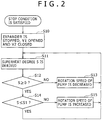
- control contents of the control unit 50 at the time of the forced circulation will be described with reference to FIG. 2 .
- the expander control section 51 stops the expander 42, and the valve control section 52 opens the bypass valve V1 and closes the shut-off valve V2 (Step S10). It is noted that the control by the valve control section 52 may be performed at the same time as the control by the expander control section 51, or before and after the control by the expander control section 51.
- the inflow control section 53 derives a superheat degree S based on each detection value of the temperature sensor 55 and the pressure sensor 56 (Step S11) and determines whether or not the superheat degree S is zero or more (Step S12). Based on this result, if it is determined that the superheat degree S is below zero (NO in Step 12), i.e., that an inflow rate of the liquid-phase working medium into the heat exchanger 30 is too high so that the liquid-phase working medium is flowing out from the heat exchanger 30, the inflow control section 53 reduces the rotation speed of the pump 46 (Step S13) and the Step 11 is repeated. In this step, a decrement amount of the rotation speed of the pump 46 is determined based on a previously prepared table.
- Step S14 it is then determined whether or not the superheat degree S is a predetermined upper limit value S1 or less.
- the inflow control section 53 increases the rotation speed of the pump 46 (Step S15) and the Step 11 is repeated. In this step, an increment amount of the rotation speed of the pump 46 is determined based on a previously prepared table.
- Step 11 is repeated without changing the rotation speed of the pump 46.
- the superheat degree of the working medium at the time of the forced circulation can be kept in a fixed range where a lower limit value thereof is zero or more and an upper limit value thereof is S1 or less.
- This control allows the use of more latent heat of the working medium, thus the compressed gas can be cooled more efficiently as compared with a case where the liquid-phase working medium flows out of the heat exchanger 30 or a case where the vapor-phase working medium having an excessively high temperature flows out of the heat exchanger 30.
- the vapor-phase working medium having the superheat degree of slightly higher than zero flows out of the heat exchanger 30, there is a case where the working medium is converted into a gas-liquid dual phase by radiating heat at some midpoint before reaching the expander 42 and, as a result, the working medium in the gas-liquid dual phase flows into the expander 42.
- a number value slightly higher than zero may be set as the lower limit value in the Step 12 in order to avoid the gas-liquid dual phase.
- the compressing device 1 In the foregoing, a structure and operation of the compressing device 1 have been described.
- a stop condition is satisfied during operation of a compressor, an expander is caused to stop, and, as a result, a working medium is unable to circulate in a circulation flow passage through the expander.
- the working medium is allowed to continuously circulate in the circulation flow passage 48 through the bypass flow passage 49 even if the expander 42 is caused to stop. In this manner, the compressed gas can be continuously cooled by the working medium in the heat exchanger 30.
- the inflow control section 53 also adjusts the rotation speed of the pump 46 so that the superheat degree of the working medium flowing into the heat exchanger 30 is the lower limit value or more and the upper limit value S1 or less.
- the first flow passage 34 is arranged on the upstream side of the second flow passage 36 in the heat exchanger 30, thus heat energy of the compressed gas is effectively recovered by the working medium flowing through the first flow passage 34 before the compressed gas is cooled by the cooling fluid flowing through the second flow passage 36. It is therefore possible to recover more energy from the compressed gas by the working medium.
- the compressed gas flows through the inner space of the casing 39, thus a pressure loss caused in the compressed gas can be reduced as compared with a case of circulating the compressed gas through a pipe.
- the first flow passage 34 and the second flow passage 36 are tubes extending in a meandering manner, thus heat can be efficiently recovered from the compressed gas.
- a plurality of fins 35 and 37 are respectively formed on outer wall faces of the first flow passage 34 and the second flow passage 36, a contact area between the compressed gas and the first flow passage 34 and a contact area between the compressed gas and the second flow passage 36 are each increased, thus a cooling efficiency of the compressed gas is improved.
- the bypass valve V1 may be configured to be opened to allow the working medium to circulate in the circulation flow passage 48 through the bypass flow passage 49.
- the inflow control section 53 adjusts the rotation speed of the pump 46 so that the superheat degree of the working medium flowing into the heat exchanger 30 is the lower limit value or more and the upper limit value S1 or less.
- the bypass condition for circulating the working medium through the bypass flow passage 49 is not necessarily the same as the stop condition mentioned above, and the bypass condition may be set on a situation where the expander 42 is not rotated or rotated at a low speed, i.e., a situation where the working medium can not be sufficiently circulated in the circulation flow passage 48 through the expander 42.
- the compressed gas can be cooled by the working medium in the heat exchanger 30 regardless of operation conditions of the expander 42.
- an expansion valve may be arranged on the bypass flow passage 49.
- the working medium can be surely condensed during a stop of the expander 42 by adjusting an opening of the expansion valve and thereby expanding the vapor-phase working medium even in a case where the condenser 44 in use has a low cooling capacity.
- the aforementioned embodiments show an example where, at the time of the forced circulation, the inflow control section 53 adjusts the inflow amount of the liquid-phase working medium into the heat exchanger 30 by controlling the rotation speed of the pump 46, however a means for adjusting the inflow amount is not limited thereto.
- the inflow control section 53 may adjust the inflow amount of the liquid-phase working medium into the heat exchanger 30 by adjusting an opening of the return valve.
- the compressing device 1 may include two or more of compressors and heat exchangers.
- the gas flow passage is arranged in such a manner that the compressed gas discharged from a first compressor is cooled by a first heat exchanger and further compressed by a second compressor, then after being cooled by a second heat exchanger, the compressed gas is supplied to an outside.
- Each of the heat exchangers may be arranged in series or in parallel on the circulation flow passage 48 for the working medium.
- the first flow passage 34 and the second flow passage 36 may be separately formed in different heat exchangers.
- the second flow passage 36 may be removed from the heat exchanger 30.
- a switching valve for switching a flow of the working medium from the heat exchanger 30 to the bypass flow passage 49 and a flow of the working medium from the heat exchanger 30 to the expander 42 may be used.
- a rotary machine may be connected to the expander 42 as a power recovery unit.
- the second flow passage 36 in the heat exchanger 30 and the condenser 44 may be arranged in parallel on the cooling fluid flow passage 60.
- the condenser 44 may be arranged on a downstream side of the second flow passage 36 on the cooling fluid flow passage 60.
- the generator 43 does not necessarily include the inverter or the converter.
Landscapes
- Engineering & Computer Science (AREA)
- Mechanical Engineering (AREA)
- General Engineering & Computer Science (AREA)
- Physics & Mathematics (AREA)
- Thermal Sciences (AREA)
- Chemical & Material Sciences (AREA)
- Combustion & Propulsion (AREA)
- Engine Equipment That Uses Special Cycles (AREA)
- General Physics & Mathematics (AREA)
- Control Of Turbines (AREA)
- Structures Of Non-Positive Displacement Pumps (AREA)
- Applications Or Details Of Rotary Compressors (AREA)
Claims (4)
- Verdichtungsvorrichtung (1) mit
einem Verdichter (10) zum Verdichten eines Gases;
einer Wärmeenergiewiederherstellungseinheit (20) zum Wiederherstellen einer Wärmeenergie eines verdichteten Gases, das von dem Verdichter (10) abgegeben wurde, durch Einsetzen eines Rankine-Kreises unter Verwendung eines Arbeitsmediums,
wobei die Wärmeenergiewiederherstellungseinheit (20) hat
einen Wärmetauscher (30) zum Wiederherstellen von Wärme des verdichteten Gases durch Austauschen von Wärme zwischen dem verdichteten Gas und dem Arbeitsmedium;
einen Expander (42) zum Expandieren des Arbeitsmediums, das mit dem verdichteten Gas in dem Wärmetauscher (30) Wärme-getauscht wurde;
eine Leistungswiederherstellungseinheit (43) zum Wiederherstellen einer Leistung von dem Expander (42);
einen Kondensator (44) zum Kondensieren des aus dem Expander (42) strömenden Arbeitsmediums;
eine Pumpe (46) zum Senden des aus dem Kondensator (44) strömenden Arbeitsmediums zu dem Wärmetauscher (46);
einen Zirkulationsströmungsdurchtritt (48) zum Verbinden des Wärmetauschers (30), des Expanders (42), des Kondensators (44) und der Pumpe (46);
einen Umgehungsströmungsdurchtritt (49), der mit dem Zirkulationsströmungsdurchtritt (48) verbunden ist, um den Expander (42) zu umgehen; und
einem Umgehungsventil (V1) zum Öffnen und Schließen des Umgehungsströmungsdurchtritts (49);
gekennzeichnet durch
ein Absperrventil (V2) zum Absperren eines Einströmens des Arbeitsmediums in den Expander (42); und
eine Steuereinheit (50) zum Umschalten zwischen einem Zustand, in dem das Arbeitsmedium in dem Zirkulationsströmungsdurchtritt (48) durch den Expander (42) zirkuliert wird und einem Zustand, in dem das Arbeitsmedium in dem Zirkulationsströmungsdurchtritt (48) durch den Umgehungsströmungsdurchtritt (49) durch das Steuern des Umgehungsventils (V1) und des Sperrventils (V2) zirkuliert wird, wobei die Verdichtungsvorrichtung außerdem umfasst
einen Temperatursensor (55) zum Erfassen einer Temperatur des Arbeitsmediums, der zwischen dem Wärmetauscher (30) und dem Expander (42) in dem Zirkulationsströmungsdurchtritt (48) angeordnet ist; und
einen Drucksensor (56) zum Erfassen eines Drucks des Arbeitsmediums, der zwischen dem Wärmetauscher (30) und dem Expander (42) in dem Zirkulationsströmungsdurchtritt (48) angeordnet ist,
wobei die Steuereinheit (50) einen Überheizgrad des Arbeitsmediums unter Verwendung der durch den Temperatursensor (55) erhaltenen Temperatur und des durch den Drucksensor (56) erhaltenen Drucks berechnet; und
eine Einströmmenge des Arbeitsmediums in den Wärmetauscher (30) so anpasst, dass der Überheizgrad ein vorbestimmter unterer Grenzwert oder höher wird, wobei der vorbestimmte untere Grenzwert größer als oder gleich Null ist, und ebenfalls ein vorbestimmter oberer Grenzwert oder weniger wird, indem eine Drehzahl der Pumpe (46) während des Zustands, in dem das Arbeitsmedium in dem Zirkulationsströmungsdurchtritt (48) durch den Umgehungsströmungsdurchtritt (49) zirkuliert wird, gesteuert wird. - Verdichtungsvorrichtung (1) mit
einem Verdichter (10) zum Verdichten eines Gases; und
einer Wärmeenergiewiederherstellungseinheit (20) zum Wiederherstellen einer Wärmeenergie eines verdichteten Gases, das von dem Verdichter (10) abgegeben wurde, durch Einsetzen eines Rankine-Kreises unter Verwendung eines Arbeitsmediums,
wobei die Wärmeenergiewiederherstellungseinheit (20) hat
einen Wärmetauscher (30) zum Wiederherstellen der Wärme des verdichteten Gases durch Austauschen von Wärme zwischen dem verdichteten Gas und dem Arbeitsmedium;
einen Expander (42) zum Expandieren des Arbeitsmediums, das mit dem verdichteten Gas in dem Wärmetauscher (30) Wärme getauscht wird;
eine Leistungswiederherstellungseinheit (43) zum Wiederherstellen einer Leistung von dem Expander (42);
einen Kondensator (44) zum Kondensieren des aus dem Expander (42) strömenden Arbeitsmediums;
eine Pumpe (46) zum Senden des aus dem Kondensator (44) strömenden Arbeitsmediums zu dem Wärmetauscher (46);
einen Zirkulationsströmungsdurchtritt (48) zum Verbinden des Wärmetauschers (30), des Expanders (42), des Kondensators (44) und der Pumpe (46);
einen Umgehungsströmungsdurchtritt (49), der mit dem Zirkulationsströmungsdurchtritt (48) durch Umgehen des Expanders (42) verbunden ist; und
ein Umgehungsventil (V1) zum Öffnen und Schließen des Umgehungsströmungsdurchtritts (49);
gekennzeichnet durch
ein Absperrventil (V2) zum Absperren eines Einströmens des Arbeitsmediums in den Expander (42); und
eine Steuereinheit (50) zum Umschalten zwischen einem Zustand, in dem das Arbeitsmedium in dem Zirkulationsströmungsdurchtritt (48) durch den Expander (42) zirkuliert wird, und einem Zustand, in dem das Arbeitsmedium in dem Zirkulationsströmungsdurchtritt (48) durch den Umgehungsströmungsdurchtritt (49) zirkuliert wird, durch Steuern des Umgehungsventils (V1) und des Absperrventils (V2),
wobei der Wärmetauscher (30) einen Gasströmungsdurchtritt (32) hat, durch den das von dem Verdichter (10) abgegebene verdichtete Gas strömt;
einen ersten Strömungsdurchtritt (34), durch den das Arbeitsmedium strömt, der in einer Position angeordnet ist, in der er in der Lage ist, Wärme zwischen dem Arbeitsmedium und dem verdichteten Gas auszutauschen; und
einen zweiten Strömungsdurchtritt (36), durch den ein Kühlfluid zum Kühlen des verdichteten Gases strömt, da er in einer Position angeordnet ist, in der er in der Lage ist, eine Wärme zwischen dem Kühlfluid und dem verdichteten Gas auszutauschen. - Verdichtungsvorrichtung nach Anspruch 2,
wobei der erste Strömungsdurchtritt (34) an einer stromaufwärts liegenden Seite des zweiten Strömungsdurchtritts (36) in einer Strömungsrichtung des verdichteten Gases in den Wärmetauscher (30) angeordnet ist. - Verdichtungsvorrichtung nach Anspruch 2,
wobei:der Gasströmungsdurchtritt (32) ein Innenraum eines Gehäuses (39) des Wärmetauschers (30) ist;der erste Strömungsdurchtritt (34) und der zweite Strömungsdurchtritt (36) Rohre sind, die sich in einer mäanderartigen Weise in dem inneren Raum erstrecken; undeine Mehrzahl Flossen (37) an äußeren Randflächen des ersten Strömungsdurchtritts (34) und des zweiten Strömungsdurchtritts (36) ausgebildet sind.
Applications Claiming Priority (1)
| Application Number | Priority Date | Filing Date | Title |
|---|---|---|---|
| JP2014180814A JP6342755B2 (ja) | 2014-09-05 | 2014-09-05 | 圧縮装置 |
Publications (2)
| Publication Number | Publication Date |
|---|---|
| EP2993353A1 EP2993353A1 (de) | 2016-03-09 |
| EP2993353B1 true EP2993353B1 (de) | 2017-12-20 |
Family
ID=53886823
Family Applications (1)
| Application Number | Title | Priority Date | Filing Date |
|---|---|---|---|
| EP15175439.7A Not-in-force EP2993353B1 (de) | 2014-09-05 | 2015-07-06 | Verdichtungsvorrichtung |
Country Status (6)
| Country | Link |
|---|---|
| US (1) | US10234183B2 (de) |
| EP (1) | EP2993353B1 (de) |
| JP (1) | JP6342755B2 (de) |
| KR (1) | KR101707744B1 (de) |
| CN (1) | CN105401991B (de) |
| DK (1) | DK2993353T3 (de) |
Families Citing this family (14)
| Publication number | Priority date | Publication date | Assignee | Title |
|---|---|---|---|---|
| JP2018127948A (ja) * | 2017-02-08 | 2018-08-16 | 株式会社神戸製鋼所 | エネルギー回収装置 |
| JP6769888B2 (ja) * | 2017-02-09 | 2020-10-14 | 株式会社神戸製鋼所 | 熱エネルギー回収装置 |
| JP6944262B2 (ja) * | 2017-03-29 | 2021-10-06 | 株式会社神戸製鋼所 | 圧縮空気貯蔵発電装置 |
| US11592009B2 (en) | 2021-04-02 | 2023-02-28 | Ice Thermal Harvesting, Llc | Systems and methods for generation of electrical power at a drilling rig |
| US11293414B1 (en) | 2021-04-02 | 2022-04-05 | Ice Thermal Harvesting, Llc | Systems and methods for generation of electrical power in an organic rankine cycle operation |
| US11421663B1 (en) | 2021-04-02 | 2022-08-23 | Ice Thermal Harvesting, Llc | Systems and methods for generation of electrical power in an organic Rankine cycle operation |
| US11326550B1 (en) | 2021-04-02 | 2022-05-10 | Ice Thermal Harvesting, Llc | Systems and methods utilizing gas temperature as a power source |
| US11280322B1 (en) | 2021-04-02 | 2022-03-22 | Ice Thermal Harvesting, Llc | Systems for generating geothermal power in an organic Rankine cycle operation during hydrocarbon production based on wellhead fluid temperature |
| US12312981B2 (en) * | 2021-04-02 | 2025-05-27 | Ice Thermal Harvesting, Llc | Systems and methods utilizing gas temperature as a power source |
| US11486370B2 (en) | 2021-04-02 | 2022-11-01 | Ice Thermal Harvesting, Llc | Modular mobile heat generation unit for generation of geothermal power in organic Rankine cycle operations |
| US11493029B2 (en) | 2021-04-02 | 2022-11-08 | Ice Thermal Harvesting, Llc | Systems and methods for generation of electrical power at a drilling rig |
| US11480074B1 (en) | 2021-04-02 | 2022-10-25 | Ice Thermal Harvesting, Llc | Systems and methods utilizing gas temperature as a power source |
| US12534990B2 (en) | 2022-12-29 | 2026-01-27 | Ice Thermal Harvesting, Llc | Power generation assemblies for hydraulic fracturing systems and methods |
| US12180861B1 (en) | 2022-12-30 | 2024-12-31 | Ice Thermal Harvesting, Llc | Systems and methods to utilize heat carriers in conversion of thermal energy |
Citations (1)
| Publication number | Priority date | Publication date | Assignee | Title |
|---|---|---|---|---|
| WO2014112326A1 (ja) * | 2013-01-16 | 2014-07-24 | パナソニック株式会社 | ランキンサイクル装置 |
Family Cites Families (24)
| Publication number | Priority date | Publication date | Assignee | Title |
|---|---|---|---|---|
| US4765144A (en) * | 1986-01-13 | 1988-08-23 | Spacer John P | Solar-powered Rankine cycle pumping engine |
| US20030213246A1 (en) * | 2002-05-15 | 2003-11-20 | Coll John Gordon | Process and device for controlling the thermal and electrical output of integrated micro combined heat and power generation systems |
| JP4277608B2 (ja) * | 2003-07-10 | 2009-06-10 | 株式会社日本自動車部品総合研究所 | ランキンサイクル |
| US20090211253A1 (en) | 2005-06-16 | 2009-08-27 | Utc Power Corporation | Organic Rankine Cycle Mechanically and Thermally Coupled to an Engine Driving a Common Load |
| JP4684882B2 (ja) * | 2005-12-21 | 2011-05-18 | 株式会社デンソー | 流体機械 |
| US20080134699A1 (en) * | 2006-11-08 | 2008-06-12 | Imi Cornelius Inc. | Refrigeration systems having prescriptive refrigerant flow control |
| JP4978519B2 (ja) * | 2007-03-22 | 2012-07-18 | ダイキン工業株式会社 | タービン発電機及びタービン発電機を備えた冷凍装置 |
| US8459053B2 (en) * | 2007-10-08 | 2013-06-11 | Emerson Climate Technologies, Inc. | Variable speed compressor protection system and method |
| GB0808200D0 (en) * | 2008-05-06 | 2008-06-11 | Invista Technologies Srl | Power recovery |
| JP5495293B2 (ja) | 2009-07-06 | 2014-05-21 | 株式会社日立産機システム | 圧縮機 |
| CN101769179A (zh) * | 2010-02-01 | 2010-07-07 | 江西佳能新能源发展有限公司 | 一种环保节能减排系统 |
| CN102859295B (zh) * | 2010-04-28 | 2014-08-20 | 松下电器产业株式会社 | 制冷循环装置 |
| SE535877C2 (sv) * | 2010-05-25 | 2013-01-29 | Scania Cv Ab | Kylarrangemang hos ett fordon som drivs av en överladdad förbränningsmotor |
| MX2013002944A (es) * | 2010-09-20 | 2014-01-24 | Un sistema y metodo para almacenar energia y purificar fluido. | |
| US20120159923A1 (en) * | 2010-12-23 | 2012-06-28 | General Electric Company | System and method for using gas turbine intercooler heat in a bottoming steam cycle |
| US9807908B2 (en) * | 2011-06-30 | 2017-10-31 | Parker-Hannifin Corporation | Pumped liquid cooling system using a phase change fluid with additional subambient cooling |
| JP2013057256A (ja) * | 2011-09-07 | 2013-03-28 | Ihi Corp | 圧縮機のエネルギー回収システム |
| JP5716837B2 (ja) * | 2011-09-30 | 2015-05-13 | 日産自動車株式会社 | エンジン廃熱利用装置 |
| JP5929450B2 (ja) * | 2012-04-16 | 2016-06-08 | 三菱電機株式会社 | 冷凍サイクル装置 |
| JP5721676B2 (ja) * | 2012-09-14 | 2015-05-20 | 株式会社神戸製鋼所 | 補助動力発生装置及びこの装置の運転方法 |
| US20140075941A1 (en) | 2012-09-14 | 2014-03-20 | Kabushiki Kaisha Kobe Seiko Sho (Kobe Steel, Ltd.) | Power generating apparatus and operation method thereof |
| JP5934074B2 (ja) * | 2012-10-16 | 2016-06-15 | 株式会社日立産機システム | ガス圧縮機 |
| JP6179735B2 (ja) | 2012-12-06 | 2017-08-16 | パナソニックIpマネジメント株式会社 | 熱電併給システム |
| CN103147812B (zh) | 2013-03-25 | 2016-03-30 | 上海西重所重型机械成套有限公司 | 一种螺杆膨胀机式烟气余热发电装置 |
-
2014
- 2014-09-05 JP JP2014180814A patent/JP6342755B2/ja not_active Expired - Fee Related
-
2015
- 2015-07-06 DK DK15175439.7T patent/DK2993353T3/en active
- 2015-07-06 EP EP15175439.7A patent/EP2993353B1/de not_active Not-in-force
- 2015-07-08 US US14/793,922 patent/US10234183B2/en not_active Expired - Fee Related
- 2015-09-02 KR KR1020150123935A patent/KR101707744B1/ko not_active Expired - Fee Related
- 2015-09-02 CN CN201510553893.7A patent/CN105401991B/zh not_active Expired - Fee Related
Patent Citations (1)
| Publication number | Priority date | Publication date | Assignee | Title |
|---|---|---|---|---|
| WO2014112326A1 (ja) * | 2013-01-16 | 2014-07-24 | パナソニック株式会社 | ランキンサイクル装置 |
Also Published As
| Publication number | Publication date |
|---|---|
| CN105401991B (zh) | 2017-04-12 |
| DK2993353T3 (en) | 2018-02-26 |
| JP2016056686A (ja) | 2016-04-21 |
| US20160069600A1 (en) | 2016-03-10 |
| CN105401991A (zh) | 2016-03-16 |
| KR101707744B1 (ko) | 2017-02-16 |
| JP6342755B2 (ja) | 2018-06-13 |
| KR20160029680A (ko) | 2016-03-15 |
| US10234183B2 (en) | 2019-03-19 |
| EP2993353A1 (de) | 2016-03-09 |
Similar Documents
| Publication | Publication Date | Title |
|---|---|---|
| US10234183B2 (en) | Compressing device | |
| JP6315814B2 (ja) | エネルギー回収装置及び圧縮装置並びにエネルギー回収方法 | |
| EP2204902B1 (de) | Abwärme nutzende vorrichtung für einen verbrennungsmotor | |
| KR101600687B1 (ko) | 배열 회수 장치 및 배열 회수 장치의 운전 제어 방법 | |
| US10184359B2 (en) | Waste heat recovery device and waste heat recovery method | |
| JP5621721B2 (ja) | ランキンサイクル | |
| JP2010174848A (ja) | 排熱回生システム | |
| JP2013231377A (ja) | 廃熱回生システム | |
| JP6433749B2 (ja) | 熱エネルギー回収装置 | |
| JP2013011258A (ja) | ランキンサイクル | |
| JP4765675B2 (ja) | 冷凍サイクル装置 | |
| KR101639535B1 (ko) | 열 에너지 회수 장치 | |
| JP6190330B2 (ja) | 熱エネルギー回収装置 | |
| JP6163145B2 (ja) | 熱エネルギー回収装置 | |
| JP6616235B2 (ja) | 排熱回収システム | |
| KR102018710B1 (ko) | 열에너지 회수 장치 | |
| KR101873692B1 (ko) | 열 에너지 회수 시스템 | |
| KR102179759B1 (ko) | 열 에너지 회수 장치 및 그 운전 방법 | |
| US10851678B2 (en) | Thermal energy recovery device and startup operation method for the same |
Legal Events
| Date | Code | Title | Description |
|---|---|---|---|
| PUAI | Public reference made under article 153(3) epc to a published international application that has entered the european phase |
Free format text: ORIGINAL CODE: 0009012 |
|
| 17P | Request for examination filed |
Effective date: 20150706 |
|
| AK | Designated contracting states |
Kind code of ref document: A1 Designated state(s): AL AT BE BG CH CY CZ DE DK EE ES FI FR GB GR HR HU IE IS IT LI LT LU LV MC MK MT NL NO PL PT RO RS SE SI SK SM TR |
|
| AX | Request for extension of the european patent |
Extension state: BA ME |
|
| 17Q | First examination report despatched |
Effective date: 20170201 |
|
| REG | Reference to a national code |
Ref country code: DE Ref legal event code: R079 Ref document number: 602015006773 Country of ref document: DE Free format text: PREVIOUS MAIN CLASS: F04C0023000000 Ipc: F01K0013020000 |
|
| GRAP | Despatch of communication of intention to grant a patent |
Free format text: ORIGINAL CODE: EPIDOSNIGR1 |
|
| RIC1 | Information provided on ipc code assigned before grant |
Ipc: F25B 49/02 20060101ALI20170612BHEP Ipc: F04C 23/00 20060101ALI20170612BHEP Ipc: F25B 41/04 20060101ALI20170612BHEP Ipc: F04C 29/04 20060101ALI20170612BHEP Ipc: F01K 13/02 20060101AFI20170612BHEP |
|
| INTG | Intention to grant announced |
Effective date: 20170704 |
|
| GRAS | Grant fee paid |
Free format text: ORIGINAL CODE: EPIDOSNIGR3 |
|
| GRAA | (expected) grant |
Free format text: ORIGINAL CODE: 0009210 |
|
| AK | Designated contracting states |
Kind code of ref document: B1 Designated state(s): AL AT BE BG CH CY CZ DE DK EE ES FI FR GB GR HR HU IE IS IT LI LT LU LV MC MK MT NL NO PL PT RO RS SE SI SK SM TR |
|
| REG | Reference to a national code |
Ref country code: GB Ref legal event code: FG4D |
|
| REG | Reference to a national code |
Ref country code: CH Ref legal event code: EP |
|
| REG | Reference to a national code |
Ref country code: IE Ref legal event code: FG4D |
|
| REG | Reference to a national code |
Ref country code: AT Ref legal event code: REF Ref document number: 956589 Country of ref document: AT Kind code of ref document: T Effective date: 20180115 |
|
| REG | Reference to a national code |
Ref country code: DE Ref legal event code: R096 Ref document number: 602015006773 Country of ref document: DE |
|
| REG | Reference to a national code |
Ref country code: DK Ref legal event code: T3 Effective date: 20180221 |
|
| REG | Reference to a national code |
Ref country code: SE Ref legal event code: TRGR |
|
| REG | Reference to a national code |
Ref country code: NL Ref legal event code: MP Effective date: 20171220 |
|
| PG25 | Lapsed in a contracting state [announced via postgrant information from national office to epo] |
Ref country code: LT Free format text: LAPSE BECAUSE OF FAILURE TO SUBMIT A TRANSLATION OF THE DESCRIPTION OR TO PAY THE FEE WITHIN THE PRESCRIBED TIME-LIMIT Effective date: 20171220 Ref country code: NO Free format text: LAPSE BECAUSE OF FAILURE TO SUBMIT A TRANSLATION OF THE DESCRIPTION OR TO PAY THE FEE WITHIN THE PRESCRIBED TIME-LIMIT Effective date: 20180320 Ref country code: FI Free format text: LAPSE BECAUSE OF FAILURE TO SUBMIT A TRANSLATION OF THE DESCRIPTION OR TO PAY THE FEE WITHIN THE PRESCRIBED TIME-LIMIT Effective date: 20171220 |
|
| REG | Reference to a national code |
Ref country code: LT Ref legal event code: MG4D |
|
| REG | Reference to a national code |
Ref country code: AT Ref legal event code: MK05 Ref document number: 956589 Country of ref document: AT Kind code of ref document: T Effective date: 20171220 |
|
| PG25 | Lapsed in a contracting state [announced via postgrant information from national office to epo] |
Ref country code: LV Free format text: LAPSE BECAUSE OF FAILURE TO SUBMIT A TRANSLATION OF THE DESCRIPTION OR TO PAY THE FEE WITHIN THE PRESCRIBED TIME-LIMIT Effective date: 20171220 Ref country code: RS Free format text: LAPSE BECAUSE OF FAILURE TO SUBMIT A TRANSLATION OF THE DESCRIPTION OR TO PAY THE FEE WITHIN THE PRESCRIBED TIME-LIMIT Effective date: 20171220 Ref country code: HR Free format text: LAPSE BECAUSE OF FAILURE TO SUBMIT A TRANSLATION OF THE DESCRIPTION OR TO PAY THE FEE WITHIN THE PRESCRIBED TIME-LIMIT Effective date: 20171220 Ref country code: GR Free format text: LAPSE BECAUSE OF FAILURE TO SUBMIT A TRANSLATION OF THE DESCRIPTION OR TO PAY THE FEE WITHIN THE PRESCRIBED TIME-LIMIT Effective date: 20180321 Ref country code: BG Free format text: LAPSE BECAUSE OF FAILURE TO SUBMIT A TRANSLATION OF THE DESCRIPTION OR TO PAY THE FEE WITHIN THE PRESCRIBED TIME-LIMIT Effective date: 20180320 |
|
| PG25 | Lapsed in a contracting state [announced via postgrant information from national office to epo] |
Ref country code: NL Free format text: LAPSE BECAUSE OF FAILURE TO SUBMIT A TRANSLATION OF THE DESCRIPTION OR TO PAY THE FEE WITHIN THE PRESCRIBED TIME-LIMIT Effective date: 20171220 |
|
| PG25 | Lapsed in a contracting state [announced via postgrant information from national office to epo] |
Ref country code: CZ Free format text: LAPSE BECAUSE OF FAILURE TO SUBMIT A TRANSLATION OF THE DESCRIPTION OR TO PAY THE FEE WITHIN THE PRESCRIBED TIME-LIMIT Effective date: 20171220 Ref country code: SK Free format text: LAPSE BECAUSE OF FAILURE TO SUBMIT A TRANSLATION OF THE DESCRIPTION OR TO PAY THE FEE WITHIN THE PRESCRIBED TIME-LIMIT Effective date: 20171220 Ref country code: ES Free format text: LAPSE BECAUSE OF FAILURE TO SUBMIT A TRANSLATION OF THE DESCRIPTION OR TO PAY THE FEE WITHIN THE PRESCRIBED TIME-LIMIT Effective date: 20171220 Ref country code: EE Free format text: LAPSE BECAUSE OF FAILURE TO SUBMIT A TRANSLATION OF THE DESCRIPTION OR TO PAY THE FEE WITHIN THE PRESCRIBED TIME-LIMIT Effective date: 20171220 Ref country code: CY Free format text: LAPSE BECAUSE OF FAILURE TO SUBMIT A TRANSLATION OF THE DESCRIPTION OR TO PAY THE FEE WITHIN THE PRESCRIBED TIME-LIMIT Effective date: 20171220 |
|
| PG25 | Lapsed in a contracting state [announced via postgrant information from national office to epo] |
Ref country code: RO Free format text: LAPSE BECAUSE OF FAILURE TO SUBMIT A TRANSLATION OF THE DESCRIPTION OR TO PAY THE FEE WITHIN THE PRESCRIBED TIME-LIMIT Effective date: 20171220 Ref country code: IS Free format text: LAPSE BECAUSE OF FAILURE TO SUBMIT A TRANSLATION OF THE DESCRIPTION OR TO PAY THE FEE WITHIN THE PRESCRIBED TIME-LIMIT Effective date: 20180420 Ref country code: PL Free format text: LAPSE BECAUSE OF FAILURE TO SUBMIT A TRANSLATION OF THE DESCRIPTION OR TO PAY THE FEE WITHIN THE PRESCRIBED TIME-LIMIT Effective date: 20171220 Ref country code: AT Free format text: LAPSE BECAUSE OF FAILURE TO SUBMIT A TRANSLATION OF THE DESCRIPTION OR TO PAY THE FEE WITHIN THE PRESCRIBED TIME-LIMIT Effective date: 20171220 Ref country code: IT Free format text: LAPSE BECAUSE OF FAILURE TO SUBMIT A TRANSLATION OF THE DESCRIPTION OR TO PAY THE FEE WITHIN THE PRESCRIBED TIME-LIMIT Effective date: 20171220 Ref country code: SM Free format text: LAPSE BECAUSE OF FAILURE TO SUBMIT A TRANSLATION OF THE DESCRIPTION OR TO PAY THE FEE WITHIN THE PRESCRIBED TIME-LIMIT Effective date: 20171220 |
|
| REG | Reference to a national code |
Ref country code: DE Ref legal event code: R097 Ref document number: 602015006773 Country of ref document: DE |
|
| PLBE | No opposition filed within time limit |
Free format text: ORIGINAL CODE: 0009261 |
|
| STAA | Information on the status of an ep patent application or granted ep patent |
Free format text: STATUS: NO OPPOSITION FILED WITHIN TIME LIMIT |
|
| 26N | No opposition filed |
Effective date: 20180921 |
|
| PG25 | Lapsed in a contracting state [announced via postgrant information from national office to epo] |
Ref country code: SI Free format text: LAPSE BECAUSE OF FAILURE TO SUBMIT A TRANSLATION OF THE DESCRIPTION OR TO PAY THE FEE WITHIN THE PRESCRIBED TIME-LIMIT Effective date: 20171220 |
|
| REG | Reference to a national code |
Ref country code: CH Ref legal event code: PL |
|
| PG25 | Lapsed in a contracting state [announced via postgrant information from national office to epo] |
Ref country code: LU Free format text: LAPSE BECAUSE OF NON-PAYMENT OF DUE FEES Effective date: 20180706 Ref country code: MC Free format text: LAPSE BECAUSE OF FAILURE TO SUBMIT A TRANSLATION OF THE DESCRIPTION OR TO PAY THE FEE WITHIN THE PRESCRIBED TIME-LIMIT Effective date: 20171220 |
|
| REG | Reference to a national code |
Ref country code: BE Ref legal event code: MM Effective date: 20180731 |
|
| REG | Reference to a national code |
Ref country code: IE Ref legal event code: MM4A |
|
| PG25 | Lapsed in a contracting state [announced via postgrant information from national office to epo] |
Ref country code: FR Free format text: LAPSE BECAUSE OF NON-PAYMENT OF DUE FEES Effective date: 20180731 Ref country code: CH Free format text: LAPSE BECAUSE OF NON-PAYMENT OF DUE FEES Effective date: 20180731 Ref country code: IE Free format text: LAPSE BECAUSE OF NON-PAYMENT OF DUE FEES Effective date: 20180706 Ref country code: LI Free format text: LAPSE BECAUSE OF NON-PAYMENT OF DUE FEES Effective date: 20180731 |
|
| PG25 | Lapsed in a contracting state [announced via postgrant information from national office to epo] |
Ref country code: BE Free format text: LAPSE BECAUSE OF NON-PAYMENT OF DUE FEES Effective date: 20180731 |
|
| PG25 | Lapsed in a contracting state [announced via postgrant information from national office to epo] |
Ref country code: MT Free format text: LAPSE BECAUSE OF NON-PAYMENT OF DUE FEES Effective date: 20180706 |
|
| PG25 | Lapsed in a contracting state [announced via postgrant information from national office to epo] |
Ref country code: TR Free format text: LAPSE BECAUSE OF FAILURE TO SUBMIT A TRANSLATION OF THE DESCRIPTION OR TO PAY THE FEE WITHIN THE PRESCRIBED TIME-LIMIT Effective date: 20171220 |
|
| PG25 | Lapsed in a contracting state [announced via postgrant information from national office to epo] |
Ref country code: PT Free format text: LAPSE BECAUSE OF FAILURE TO SUBMIT A TRANSLATION OF THE DESCRIPTION OR TO PAY THE FEE WITHIN THE PRESCRIBED TIME-LIMIT Effective date: 20171220 |
|
| PG25 | Lapsed in a contracting state [announced via postgrant information from national office to epo] |
Ref country code: HU Free format text: LAPSE BECAUSE OF FAILURE TO SUBMIT A TRANSLATION OF THE DESCRIPTION OR TO PAY THE FEE WITHIN THE PRESCRIBED TIME-LIMIT; INVALID AB INITIO Effective date: 20150706 Ref country code: MK Free format text: LAPSE BECAUSE OF NON-PAYMENT OF DUE FEES Effective date: 20171220 |
|
| PG25 | Lapsed in a contracting state [announced via postgrant information from national office to epo] |
Ref country code: AL Free format text: LAPSE BECAUSE OF FAILURE TO SUBMIT A TRANSLATION OF THE DESCRIPTION OR TO PAY THE FEE WITHIN THE PRESCRIBED TIME-LIMIT Effective date: 20171220 |
|
| PGFP | Annual fee paid to national office [announced via postgrant information from national office to epo] |
Ref country code: GB Payment date: 20210609 Year of fee payment: 7 |
|
| PGFP | Annual fee paid to national office [announced via postgrant information from national office to epo] |
Ref country code: SE Payment date: 20210712 Year of fee payment: 7 Ref country code: DE Payment date: 20210608 Year of fee payment: 7 Ref country code: DK Payment date: 20210712 Year of fee payment: 7 |
|
| REG | Reference to a national code |
Ref country code: DE Ref legal event code: R119 Ref document number: 602015006773 Country of ref document: DE |
|
| REG | Reference to a national code |
Ref country code: DK Ref legal event code: EBP Effective date: 20220731 |
|
| REG | Reference to a national code |
Ref country code: SE Ref legal event code: EUG |
|
| GBPC | Gb: european patent ceased through non-payment of renewal fee |
Effective date: 20220706 |
|
| PG25 | Lapsed in a contracting state [announced via postgrant information from national office to epo] |
Ref country code: SE Free format text: LAPSE BECAUSE OF NON-PAYMENT OF DUE FEES Effective date: 20220707 |
|
| PG25 | Lapsed in a contracting state [announced via postgrant information from national office to epo] |
Ref country code: GB Free format text: LAPSE BECAUSE OF NON-PAYMENT OF DUE FEES Effective date: 20220706 Ref country code: DE Free format text: LAPSE BECAUSE OF NON-PAYMENT OF DUE FEES Effective date: 20230201 |
|
| PG25 | Lapsed in a contracting state [announced via postgrant information from national office to epo] |
Ref country code: DK Free format text: LAPSE BECAUSE OF NON-PAYMENT OF DUE FEES Effective date: 20220731 |