EP2993322B1 - In-situ-regenerationsverfahren für einen denitrifikationskatalysator in abgasreinigungssystemen - Google Patents
In-situ-regenerationsverfahren für einen denitrifikationskatalysator in abgasreinigungssystemen Download PDFInfo
- Publication number
- EP2993322B1 EP2993322B1 EP14774245.6A EP14774245A EP2993322B1 EP 2993322 B1 EP2993322 B1 EP 2993322B1 EP 14774245 A EP14774245 A EP 14774245A EP 2993322 B1 EP2993322 B1 EP 2993322B1
- Authority
- EP
- European Patent Office
- Prior art keywords
- reducing agent
- catalyst layer
- denitration catalyst
- exhaust gas
- air
- Prior art date
- Legal status (The legal status is an assumption and is not a legal conclusion. Google has not performed a legal analysis and makes no representation as to the accuracy of the status listed.)
- Active
Links
Images


Classifications
-
- F—MECHANICAL ENGINEERING; LIGHTING; HEATING; WEAPONS; BLASTING
- F01—MACHINES OR ENGINES IN GENERAL; ENGINE PLANTS IN GENERAL; STEAM ENGINES
- F01N—GAS-FLOW SILENCERS OR EXHAUST APPARATUS FOR MACHINES OR ENGINES IN GENERAL; GAS-FLOW SILENCERS OR EXHAUST APPARATUS FOR INTERNAL COMBUSTION ENGINES
- F01N3/00—Exhaust or silencing apparatus having means for purifying, rendering innocuous, or otherwise treating exhaust
- F01N3/08—Exhaust or silencing apparatus having means for purifying, rendering innocuous, or otherwise treating exhaust for rendering innocuous
- F01N3/10—Exhaust or silencing apparatus having means for purifying, rendering innocuous, or otherwise treating exhaust for rendering innocuous by thermal or catalytic conversion of noxious components of exhaust
- F01N3/24—Exhaust or silencing apparatus having means for purifying, rendering innocuous, or otherwise treating exhaust for rendering innocuous by thermal or catalytic conversion of noxious components of exhaust characterised by constructional aspects of converting apparatus
- F01N3/30—Arrangements for supply of additional air
- F01N3/306—Preheating additional air
-
- B—PERFORMING OPERATIONS; TRANSPORTING
- B01—PHYSICAL OR CHEMICAL PROCESSES OR APPARATUS IN GENERAL
- B01D—SEPARATION
- B01D53/00—Separation of gases or vapours; Recovering vapours of volatile solvents from gases; Chemical or biological purification of waste gases, e.g. engine exhaust gases, smoke, fumes, flue gases, aerosols
- B01D53/34—Chemical or biological purification of waste gases
- B01D53/74—General processes for purification of waste gases; Apparatus or devices specially adapted therefor
- B01D53/86—Catalytic processes
- B01D53/8621—Removing nitrogen compounds
- B01D53/8625—Nitrogen oxides
- B01D53/8631—Processes characterised by a specific device
-
- B—PERFORMING OPERATIONS; TRANSPORTING
- B01—PHYSICAL OR CHEMICAL PROCESSES OR APPARATUS IN GENERAL
- B01D—SEPARATION
- B01D53/00—Separation of gases or vapours; Recovering vapours of volatile solvents from gases; Chemical or biological purification of waste gases, e.g. engine exhaust gases, smoke, fumes, flue gases, aerosols
- B01D53/34—Chemical or biological purification of waste gases
- B01D53/92—Chemical or biological purification of waste gases of engine exhaust gases
- B01D53/94—Chemical or biological purification of waste gases of engine exhaust gases by catalytic processes
- B01D53/9404—Removing only nitrogen compounds
- B01D53/9409—Nitrogen oxides
- B01D53/9413—Processes characterised by a specific catalyst
- B01D53/9418—Processes characterised by a specific catalyst for removing nitrogen oxides by selective catalytic reduction [SCR] using a reducing agent in a lean exhaust gas
-
- B—PERFORMING OPERATIONS; TRANSPORTING
- B01—PHYSICAL OR CHEMICAL PROCESSES OR APPARATUS IN GENERAL
- B01D—SEPARATION
- B01D53/00—Separation of gases or vapours; Recovering vapours of volatile solvents from gases; Chemical or biological purification of waste gases, e.g. engine exhaust gases, smoke, fumes, flue gases, aerosols
- B01D53/34—Chemical or biological purification of waste gases
- B01D53/92—Chemical or biological purification of waste gases of engine exhaust gases
- B01D53/94—Chemical or biological purification of waste gases of engine exhaust gases by catalytic processes
- B01D53/9404—Removing only nitrogen compounds
- B01D53/9409—Nitrogen oxides
- B01D53/9431—Processes characterised by a specific device
-
- B—PERFORMING OPERATIONS; TRANSPORTING
- B01—PHYSICAL OR CHEMICAL PROCESSES OR APPARATUS IN GENERAL
- B01D—SEPARATION
- B01D53/00—Separation of gases or vapours; Recovering vapours of volatile solvents from gases; Chemical or biological purification of waste gases, e.g. engine exhaust gases, smoke, fumes, flue gases, aerosols
- B01D53/34—Chemical or biological purification of waste gases
- B01D53/96—Regeneration, reactivation or recycling of reactants
-
- B—PERFORMING OPERATIONS; TRANSPORTING
- B01—PHYSICAL OR CHEMICAL PROCESSES OR APPARATUS IN GENERAL
- B01J—CHEMICAL OR PHYSICAL PROCESSES, e.g. CATALYSIS OR COLLOID CHEMISTRY; THEIR RELEVANT APPARATUS
- B01J23/00—Catalysts comprising metals or metal oxides or hydroxides, not provided for in group B01J21/00
- B01J23/38—Catalysts comprising metals or metal oxides or hydroxides, not provided for in group B01J21/00 of noble metals
- B01J23/40—Catalysts comprising metals or metal oxides or hydroxides, not provided for in group B01J21/00 of noble metals of the platinum group metals
- B01J23/42—Platinum
-
- B—PERFORMING OPERATIONS; TRANSPORTING
- B01—PHYSICAL OR CHEMICAL PROCESSES OR APPARATUS IN GENERAL
- B01J—CHEMICAL OR PHYSICAL PROCESSES, e.g. CATALYSIS OR COLLOID CHEMISTRY; THEIR RELEVANT APPARATUS
- B01J23/00—Catalysts comprising metals or metal oxides or hydroxides, not provided for in group B01J21/00
- B01J23/90—Regeneration or reactivation
- B01J23/96—Regeneration or reactivation of catalysts comprising metals, oxides or hydroxides of the noble metals
-
- B—PERFORMING OPERATIONS; TRANSPORTING
- B01—PHYSICAL OR CHEMICAL PROCESSES OR APPARATUS IN GENERAL
- B01J—CHEMICAL OR PHYSICAL PROCESSES, e.g. CATALYSIS OR COLLOID CHEMISTRY; THEIR RELEVANT APPARATUS
- B01J29/00—Catalysts comprising molecular sieves
- B01J29/04—Catalysts comprising molecular sieves having base-exchange properties, e.g. crystalline zeolites
- B01J29/06—Crystalline aluminosilicate zeolites; Isomorphous compounds thereof
- B01J29/40—Crystalline aluminosilicate zeolites; Isomorphous compounds thereof of the pentasil type, e.g. types ZSM-5, ZSM-8 or ZSM-11, as exemplified by patent documents US3702886, GB1334243 and US3709979, respectively
- B01J29/42—Crystalline aluminosilicate zeolites; Isomorphous compounds thereof of the pentasil type, e.g. types ZSM-5, ZSM-8 or ZSM-11, as exemplified by patent documents US3702886, GB1334243 and US3709979, respectively containing iron group metals, noble metals or copper
- B01J29/46—Iron group metals or copper
-
- B—PERFORMING OPERATIONS; TRANSPORTING
- B01—PHYSICAL OR CHEMICAL PROCESSES OR APPARATUS IN GENERAL
- B01J—CHEMICAL OR PHYSICAL PROCESSES, e.g. CATALYSIS OR COLLOID CHEMISTRY; THEIR RELEVANT APPARATUS
- B01J29/00—Catalysts comprising molecular sieves
- B01J29/90—Regeneration or reactivation
-
- B—PERFORMING OPERATIONS; TRANSPORTING
- B01—PHYSICAL OR CHEMICAL PROCESSES OR APPARATUS IN GENERAL
- B01J—CHEMICAL OR PHYSICAL PROCESSES, e.g. CATALYSIS OR COLLOID CHEMISTRY; THEIR RELEVANT APPARATUS
- B01J38/00—Regeneration or reactivation of catalysts, in general
- B01J38/02—Heat treatment
-
- B—PERFORMING OPERATIONS; TRANSPORTING
- B01—PHYSICAL OR CHEMICAL PROCESSES OR APPARATUS IN GENERAL
- B01J—CHEMICAL OR PHYSICAL PROCESSES, e.g. CATALYSIS OR COLLOID CHEMISTRY; THEIR RELEVANT APPARATUS
- B01J38/00—Regeneration or reactivation of catalysts, in general
- B01J38/04—Gas or vapour treating; Treating by using liquids vaporisable upon contacting spent catalyst
-
- F—MECHANICAL ENGINEERING; LIGHTING; HEATING; WEAPONS; BLASTING
- F01—MACHINES OR ENGINES IN GENERAL; ENGINE PLANTS IN GENERAL; STEAM ENGINES
- F01N—GAS-FLOW SILENCERS OR EXHAUST APPARATUS FOR MACHINES OR ENGINES IN GENERAL; GAS-FLOW SILENCERS OR EXHAUST APPARATUS FOR INTERNAL COMBUSTION ENGINES
- F01N3/00—Exhaust or silencing apparatus having means for purifying, rendering innocuous, or otherwise treating exhaust
- F01N3/08—Exhaust or silencing apparatus having means for purifying, rendering innocuous, or otherwise treating exhaust for rendering innocuous
- F01N3/10—Exhaust or silencing apparatus having means for purifying, rendering innocuous, or otherwise treating exhaust for rendering innocuous by thermal or catalytic conversion of noxious components of exhaust
- F01N3/105—General auxiliary catalysts, e.g. upstream or downstream of the main catalyst
- F01N3/106—Auxiliary oxidation catalysts
-
- F—MECHANICAL ENGINEERING; LIGHTING; HEATING; WEAPONS; BLASTING
- F01—MACHINES OR ENGINES IN GENERAL; ENGINE PLANTS IN GENERAL; STEAM ENGINES
- F01N—GAS-FLOW SILENCERS OR EXHAUST APPARATUS FOR MACHINES OR ENGINES IN GENERAL; GAS-FLOW SILENCERS OR EXHAUST APPARATUS FOR INTERNAL COMBUSTION ENGINES
- F01N3/00—Exhaust or silencing apparatus having means for purifying, rendering innocuous, or otherwise treating exhaust
- F01N3/08—Exhaust or silencing apparatus having means for purifying, rendering innocuous, or otherwise treating exhaust for rendering innocuous
- F01N3/10—Exhaust or silencing apparatus having means for purifying, rendering innocuous, or otherwise treating exhaust for rendering innocuous by thermal or catalytic conversion of noxious components of exhaust
- F01N3/18—Exhaust or silencing apparatus having means for purifying, rendering innocuous, or otherwise treating exhaust for rendering innocuous by thermal or catalytic conversion of noxious components of exhaust characterised by methods of operation; Control
- F01N3/20—Exhaust or silencing apparatus having means for purifying, rendering innocuous, or otherwise treating exhaust for rendering innocuous by thermal or catalytic conversion of noxious components of exhaust characterised by methods of operation; Control specially adapted for catalytic conversion ; Methods of operation or control of catalytic converters
- F01N3/2006—Periodically heating or cooling catalytic reactors, e.g. at cold starting or overheating
-
- F—MECHANICAL ENGINEERING; LIGHTING; HEATING; WEAPONS; BLASTING
- F01—MACHINES OR ENGINES IN GENERAL; ENGINE PLANTS IN GENERAL; STEAM ENGINES
- F01N—GAS-FLOW SILENCERS OR EXHAUST APPARATUS FOR MACHINES OR ENGINES IN GENERAL; GAS-FLOW SILENCERS OR EXHAUST APPARATUS FOR INTERNAL COMBUSTION ENGINES
- F01N3/00—Exhaust or silencing apparatus having means for purifying, rendering innocuous, or otherwise treating exhaust
- F01N3/08—Exhaust or silencing apparatus having means for purifying, rendering innocuous, or otherwise treating exhaust for rendering innocuous
- F01N3/10—Exhaust or silencing apparatus having means for purifying, rendering innocuous, or otherwise treating exhaust for rendering innocuous by thermal or catalytic conversion of noxious components of exhaust
- F01N3/18—Exhaust or silencing apparatus having means for purifying, rendering innocuous, or otherwise treating exhaust for rendering innocuous by thermal or catalytic conversion of noxious components of exhaust characterised by methods of operation; Control
- F01N3/20—Exhaust or silencing apparatus having means for purifying, rendering innocuous, or otherwise treating exhaust for rendering innocuous by thermal or catalytic conversion of noxious components of exhaust characterised by methods of operation; Control specially adapted for catalytic conversion ; Methods of operation or control of catalytic converters
- F01N3/2066—Selective catalytic reduction [SCR]
-
- F—MECHANICAL ENGINEERING; LIGHTING; HEATING; WEAPONS; BLASTING
- F01—MACHINES OR ENGINES IN GENERAL; ENGINE PLANTS IN GENERAL; STEAM ENGINES
- F01N—GAS-FLOW SILENCERS OR EXHAUST APPARATUS FOR MACHINES OR ENGINES IN GENERAL; GAS-FLOW SILENCERS OR EXHAUST APPARATUS FOR INTERNAL COMBUSTION ENGINES
- F01N3/00—Exhaust or silencing apparatus having means for purifying, rendering innocuous, or otherwise treating exhaust
- F01N3/08—Exhaust or silencing apparatus having means for purifying, rendering innocuous, or otherwise treating exhaust for rendering innocuous
- F01N3/10—Exhaust or silencing apparatus having means for purifying, rendering innocuous, or otherwise treating exhaust for rendering innocuous by thermal or catalytic conversion of noxious components of exhaust
- F01N3/18—Exhaust or silencing apparatus having means for purifying, rendering innocuous, or otherwise treating exhaust for rendering innocuous by thermal or catalytic conversion of noxious components of exhaust characterised by methods of operation; Control
- F01N3/22—Control of additional air supply only, e.g. using by-passes or variable air pump drives
-
- F—MECHANICAL ENGINEERING; LIGHTING; HEATING; WEAPONS; BLASTING
- F01—MACHINES OR ENGINES IN GENERAL; ENGINE PLANTS IN GENERAL; STEAM ENGINES
- F01N—GAS-FLOW SILENCERS OR EXHAUST APPARATUS FOR MACHINES OR ENGINES IN GENERAL; GAS-FLOW SILENCERS OR EXHAUST APPARATUS FOR INTERNAL COMBUSTION ENGINES
- F01N3/00—Exhaust or silencing apparatus having means for purifying, rendering innocuous, or otherwise treating exhaust
- F01N3/08—Exhaust or silencing apparatus having means for purifying, rendering innocuous, or otherwise treating exhaust for rendering innocuous
- F01N3/10—Exhaust or silencing apparatus having means for purifying, rendering innocuous, or otherwise treating exhaust for rendering innocuous by thermal or catalytic conversion of noxious components of exhaust
- F01N3/24—Exhaust or silencing apparatus having means for purifying, rendering innocuous, or otherwise treating exhaust for rendering innocuous by thermal or catalytic conversion of noxious components of exhaust characterised by constructional aspects of converting apparatus
- F01N3/30—Arrangements for supply of additional air
-
- B—PERFORMING OPERATIONS; TRANSPORTING
- B01—PHYSICAL OR CHEMICAL PROCESSES OR APPARATUS IN GENERAL
- B01D—SEPARATION
- B01D2251/00—Reactants
- B01D2251/20—Reductants
- B01D2251/208—Hydrocarbons
-
- B—PERFORMING OPERATIONS; TRANSPORTING
- B01—PHYSICAL OR CHEMICAL PROCESSES OR APPARATUS IN GENERAL
- B01D—SEPARATION
- B01D2255/00—Catalysts
- B01D2255/20—Metals or compounds thereof
- B01D2255/207—Transition metals
- B01D2255/20746—Cobalt
-
- B—PERFORMING OPERATIONS; TRANSPORTING
- B01—PHYSICAL OR CHEMICAL PROCESSES OR APPARATUS IN GENERAL
- B01D—SEPARATION
- B01D2255/00—Catalysts
- B01D2255/50—Zeolites
- B01D2255/504—ZSM 5 zeolites
-
- B—PERFORMING OPERATIONS; TRANSPORTING
- B01—PHYSICAL OR CHEMICAL PROCESSES OR APPARATUS IN GENERAL
- B01D—SEPARATION
- B01D2257/00—Components to be removed
- B01D2257/40—Nitrogen compounds
- B01D2257/404—Nitrogen oxides other than dinitrogen oxide
-
- B—PERFORMING OPERATIONS; TRANSPORTING
- B01—PHYSICAL OR CHEMICAL PROCESSES OR APPARATUS IN GENERAL
- B01D—SEPARATION
- B01D2258/00—Sources of waste gases
- B01D2258/01—Engine exhaust gases
- B01D2258/012—Diesel engines and lean burn gasoline engines
-
- F—MECHANICAL ENGINEERING; LIGHTING; HEATING; WEAPONS; BLASTING
- F01—MACHINES OR ENGINES IN GENERAL; ENGINE PLANTS IN GENERAL; STEAM ENGINES
- F01N—GAS-FLOW SILENCERS OR EXHAUST APPARATUS FOR MACHINES OR ENGINES IN GENERAL; GAS-FLOW SILENCERS OR EXHAUST APPARATUS FOR INTERNAL COMBUSTION ENGINES
- F01N2240/00—Combination or association of two or more different exhaust treating devices, or of at least one such device with an auxiliary device, not covered by indexing codes F01N2230/00 or F01N2250/00, one of the devices being
- F01N2240/02—Combination or association of two or more different exhaust treating devices, or of at least one such device with an auxiliary device, not covered by indexing codes F01N2230/00 or F01N2250/00, one of the devices being a heat exchanger
-
- F—MECHANICAL ENGINEERING; LIGHTING; HEATING; WEAPONS; BLASTING
- F01—MACHINES OR ENGINES IN GENERAL; ENGINE PLANTS IN GENERAL; STEAM ENGINES
- F01N—GAS-FLOW SILENCERS OR EXHAUST APPARATUS FOR MACHINES OR ENGINES IN GENERAL; GAS-FLOW SILENCERS OR EXHAUST APPARATUS FOR INTERNAL COMBUSTION ENGINES
- F01N2260/00—Exhaust treating devices having provisions not otherwise provided for
- F01N2260/04—Exhaust treating devices having provisions not otherwise provided for for regeneration or reactivation, e.g. of catalyst
-
- F—MECHANICAL ENGINEERING; LIGHTING; HEATING; WEAPONS; BLASTING
- F01—MACHINES OR ENGINES IN GENERAL; ENGINE PLANTS IN GENERAL; STEAM ENGINES
- F01N—GAS-FLOW SILENCERS OR EXHAUST APPARATUS FOR MACHINES OR ENGINES IN GENERAL; GAS-FLOW SILENCERS OR EXHAUST APPARATUS FOR INTERNAL COMBUSTION ENGINES
- F01N2330/00—Structure of catalyst support or particle filter
- F01N2330/06—Ceramic, e.g. monoliths
-
- F—MECHANICAL ENGINEERING; LIGHTING; HEATING; WEAPONS; BLASTING
- F01—MACHINES OR ENGINES IN GENERAL; ENGINE PLANTS IN GENERAL; STEAM ENGINES
- F01N—GAS-FLOW SILENCERS OR EXHAUST APPARATUS FOR MACHINES OR ENGINES IN GENERAL; GAS-FLOW SILENCERS OR EXHAUST APPARATUS FOR INTERNAL COMBUSTION ENGINES
- F01N2370/00—Selection of materials for exhaust purification
- F01N2370/02—Selection of materials for exhaust purification used in catalytic reactors
- F01N2370/04—Zeolitic material
-
- F—MECHANICAL ENGINEERING; LIGHTING; HEATING; WEAPONS; BLASTING
- F01—MACHINES OR ENGINES IN GENERAL; ENGINE PLANTS IN GENERAL; STEAM ENGINES
- F01N—GAS-FLOW SILENCERS OR EXHAUST APPARATUS FOR MACHINES OR ENGINES IN GENERAL; GAS-FLOW SILENCERS OR EXHAUST APPARATUS FOR INTERNAL COMBUSTION ENGINES
- F01N2510/00—Surface coverings
- F01N2510/06—Surface coverings for exhaust purification, e.g. catalytic reaction
-
- F—MECHANICAL ENGINEERING; LIGHTING; HEATING; WEAPONS; BLASTING
- F01—MACHINES OR ENGINES IN GENERAL; ENGINE PLANTS IN GENERAL; STEAM ENGINES
- F01N—GAS-FLOW SILENCERS OR EXHAUST APPARATUS FOR MACHINES OR ENGINES IN GENERAL; GAS-FLOW SILENCERS OR EXHAUST APPARATUS FOR INTERNAL COMBUSTION ENGINES
- F01N2590/00—Exhaust or silencing apparatus adapted to particular use, e.g. for military applications, airplanes, submarines
- F01N2590/02—Exhaust or silencing apparatus adapted to particular use, e.g. for military applications, airplanes, submarines for marine vessels or naval applications
-
- F—MECHANICAL ENGINEERING; LIGHTING; HEATING; WEAPONS; BLASTING
- F01—MACHINES OR ENGINES IN GENERAL; ENGINE PLANTS IN GENERAL; STEAM ENGINES
- F01N—GAS-FLOW SILENCERS OR EXHAUST APPARATUS FOR MACHINES OR ENGINES IN GENERAL; GAS-FLOW SILENCERS OR EXHAUST APPARATUS FOR INTERNAL COMBUSTION ENGINES
- F01N2610/00—Adding substances to exhaust gases
- F01N2610/03—Adding substances to exhaust gases the substance being hydrocarbons, e.g. engine fuel
-
- F—MECHANICAL ENGINEERING; LIGHTING; HEATING; WEAPONS; BLASTING
- F01—MACHINES OR ENGINES IN GENERAL; ENGINE PLANTS IN GENERAL; STEAM ENGINES
- F01N—GAS-FLOW SILENCERS OR EXHAUST APPARATUS FOR MACHINES OR ENGINES IN GENERAL; GAS-FLOW SILENCERS OR EXHAUST APPARATUS FOR INTERNAL COMBUSTION ENGINES
- F01N2610/00—Adding substances to exhaust gases
- F01N2610/08—Adding substances to exhaust gases with prior mixing of the substances with a gas, e.g. air
-
- Y—GENERAL TAGGING OF NEW TECHNOLOGICAL DEVELOPMENTS; GENERAL TAGGING OF CROSS-SECTIONAL TECHNOLOGIES SPANNING OVER SEVERAL SECTIONS OF THE IPC; TECHNICAL SUBJECTS COVERED BY FORMER USPC CROSS-REFERENCE ART COLLECTIONS [XRACs] AND DIGESTS
- Y02—TECHNOLOGIES OR APPLICATIONS FOR MITIGATION OR ADAPTATION AGAINST CLIMATE CHANGE
- Y02T—CLIMATE CHANGE MITIGATION TECHNOLOGIES RELATED TO TRANSPORTATION
- Y02T10/00—Road transport of goods or passengers
- Y02T10/10—Internal combustion engine [ICE] based vehicles
- Y02T10/12—Improving ICE efficiencies
Definitions
- the present invention relates to an on-site regeneration method of a denitration catalyst in an exhaust gas purification system, in which a liquid reducing agent, such as alcohols, hydrocarbons, etc., is added in a purification system in an exhaust gas of an internal combustion engine or the like, in more detail a purification system of an exhaust gas of an internal combustion engine, for example, marine diesel engines, etc., or the like, to remove nitrogen oxides (NOx) and also make it possible to recover a performance of the denitration catalyst.
- a liquid reducing agent such as alcohols, hydrocarbons, etc.
- PTL 1 discloses a method of reducing and removing NOx in an exhaust gas by using an alcohol and/or an ether, such as methanol and/or dimethyl ether, etc., as a reducing agent and a denitration catalyst of a proton-type ⁇ zeolite; and discloses a denitration catalyst regeneration system in which on that occasion, a denitration catalyst layer is disposed in each of exhaust gas treatment passages of branched at least two systems, one of the exhaust gas treatment passages is closed to stop the supply of the exhaust gas, and while continuing an exhaust gas treatment in the other exhaust gas treatment passage, the denitration catalyst layer of the exhaust gas treatment passage where the supply of the exhaust gas is stopped is heat treated (directly heated by a heater) at 350 to 800°C on site, thereby recovering the lowered denitration performance.
- an alcohol and/or an ether such as methanol and/or dimethyl ether, etc.
- a denitration catalyst regeneration system as function recovery structure of a denitration catalyst of an exhaust treatment apparatus of automobile, in which a first reducing agent-charging pipe for charging a reducing agent at all times and a second reducing agent-charging pipe for charging a reducing agent in due time are installed, and furthermore, in which an oxidation catalyst is inserted with respect to regulation of a reducing agent supply pressure in association with an increase of a back pressure on the upstream side of the denitration catalyst.
- GB 2 448 993 A discloses a method for operating an aftertreatment device having a urea-based selective catalyst reduction (SCR) catalyst coupled downstream of an internal combustion engine 10.
- SCR selective catalyst reduction
- the method comprises establishing a threshold urea deposit accumulation for regeneration of the SCR catalyst 14 and determining that the threshold urea deposit accumulation in the SCR catalyst has been met. In addition excess urea is injected into the exhaust following regeneration to maintain optimum urea deposition in the SCR catalyst.
- US 2006/032332 A1 relates to an exhaust system for an internal combustion engine, in particular in a motor vehicle, with an exhaust line in which an oxidation catalyst is provided for treatment of the exhaust gases coming from the internal combustion engine.
- a pre-oxidation unit may be provided in the exhaust line upstream from the oxidation catalyst and connected to a secondary fuel supply.
- the denitration catalyst purification system described in treatment is performed on site, namely on a job site by using the reducing agent, air, and a reducing agent oxidation catalyst layer as exclusively installed, without using a conventional special heating apparatus or a fuel, thereby making it possible to regenerate the denitration catalyst.
- An invention as set forth in claim 2 is concerned with the on-site regeneration method of a denitration catalyst in an exhaust gas purification system according to claim 1, which is characterized in that a heating temperature of the denitration catalyst by the high-temperature oxidation reaction gas is 500°C or higher and 800°C or lower.
- An invention as set forth in claim 3 is concerned with the on-site regeneration method of a denitration catalyst in an exhaust gas purification system according to claim 1 or 2, which is characterized in that a reducing agent supply branch line is provided on the way of a reducing agent supply main line for supplying the reducing agent into the exhaust gas on the upstream side of the denitration catalyst layer; meanwhile, an air supply branch line is provided on the way of an air supply main line for supplying air into the exhaust gas on the upstream side of the denitration catalyst layer; these reducing agent supply branch line and air supply branch line are connected to the reducing agent oxidation catalyst layer; and at the time of catalyst regeneration of the denitration catalyst layer, not only the supply of the reducing agent is switched from the reducing agent supply main line to the reducing agent supply branch line, but also the supply of air is switched from the air supply main line to the air supply branch line, thereby supplying the reducing agent and air into the reducing agent oxidation catalyst layer.
- An invention as set forth in claim 4 is concerned with the on-site regeneration method of a denitration catalyst in an exhaust gas purification system according to claim 1 or 2, which is characterized in that a reducing agent supply sub line for supplying a reducing agent of the same kind as or a reducing agent of a different kind from the reducing agent to be supplied into the exhaust gas on the upstream side of the denitration catalyst layer is connected to the reducing agent oxidation catalyst layer; meanwhile, an air supply branch line is provided on the way of an air supply main line for supplying air into the exhaust gas on the upstream side of the denitration catalyst layer; this air supply branch line is connected to the reducing agent oxidation catalyst layer; and at the time of catalyst regeneration of the denitration catalyst layer, not only the reducing agent of the same or the reducing agent of a different kind is supplied from the reducing agent supply sub line into the reducing agent oxidation catalyst layer, but also the supply of air is switched from the air supply main line to the air supply branch line, thereby supplying air into the
- An invention as set forth in claim 5 is concerned with the on-site regeneration method of a denitration catalyst in an exhaust gas purification system according to claim 1 or 2, which is characterized in that the reducing agent oxidation catalyst layer is provided with a reducing agent supply sub line for supplying a reducing agent of the same kind as or a reducing agent of a different kind from the reducing agent to be supplied into the exhaust gas on the upstream side of the denitration catalyst layer and an air supply sub line for supplying air into the reducing agent oxidation catalyst layer separately from a reducing agent supply main line for supplying a reducing agent into the exhaust gas on the upstream side of the denitration catalyst layer and an air supply main line for supplying air, respectively; and at the time of catalyst regeneration of the denitration catalyst layer, not only the reducing agent of the same or the reducing agent of a different kind is supplied from the reducing agent supply sub line into the reducing agent oxidation catalyst layer, but also air is supplied from the air supply sub line.
- An invention as set forth in claim 6 is concerned with the on-site regeneration method of a denitration catalyst in an exhaust gas purification system according to any one of claims 1 to 5, which is characterized in that a heat exchanger for air heating is installed in an exhaust passage on the downstream side of the denitration catalyst layer; in the heat exchanger, air is heated by an exhaust heat of a purified exhaust gas discharged from the denitration catalyst layer; and this heated air is supplied into the reducing agent oxidation catalyst layer, thereby causing an oxidation reaction of the reducing agent and the air.
- An invention as set forth in claim 7 is concerned with the on-site regeneration method of a denitration catalyst in an exhaust gas purification system according to any one of claims 1 to 3, which is characterized in that the reducing agent is at least one organic compound selected from the group consisting of alcohols, ethers, ketones, and hydrocarbons, and air is added to the exhaust gas on the upstream side of the denitration catalyst layer together with a vaporized reducing agent.
- the reducing agent is at least one organic compound selected from the group consisting of alcohols, ethers, ketones, and hydrocarbons
- a carbon component deposited on the denitration catalyst is removed by an appropriate heat treatment, whereby a denitration catalyst performance can be recovered, and the heat treatment is performed on site, namely on a job site by using a reducing agent, air, and a reducing agent oxidation catalyst layer as exclusively installed, without using a conventional special heating apparatus or a fuel, thereby making it possible to regenerate the denitration catalyst.
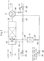
- Fig. 1 is a flow sheet showing a first embodiment of an apparatus for carrying out an on-site regeneration method of a denitration catalyst in an exhaust gas purification system according to the present invention.
- the exhaust gas purification system carries out a denitration catalyst (for example, Co/zeolite) system capable of undergoing denitration in a low temperature region of about 180 to 300°C by using an alcohol or the like (for example, ethanol) as a reducing agent.
- a denitration catalyst for example, Co/zeolite
- the reducing agent is mixed with air, introduced into a denitration catalyst reactor, and dispersed over the whole of the catalyst.
- a reducing agent-entrained air is added to an exhaust gas on the upstream side of a denitration catalyst layer (1) installed in an exhaust passage (line) (11) of an internal combustion engine, to reduce nitrogen oxides in the exhaust gas in the denitration catalyst layer (1).
- a purified gas which has been purified in the denitration catalyst layer (1) is discharged outside from an exhaust line (12).
- the reducing agent for example, ethanol
- the air is supplied by a line (14).
- the reducing agent supply main line (13) and the air supply main line (14) are connected to a merge line (15), and the reducing agent is mixed with the air, introduced from the merge line (15) into the denitration catalyst layer (1) by a nozzle (16), and dispersed over the whole of the catalyst.
- Valves (21) and (22) are provided in the reducing agent supply main line (13), and valves (23) and (24) are provided in the air supply main line (14).
- Examples of the denitration catalyst which is filled in the denitration catalyst layer (1) include catalysts having cobalt supported on zeolite, catalysts having vanadium supported on TiO 2 , and catalysts having tungsten or molybdenum supported on TiO 2 ; however, other catalysts may also be used so long as they are able to subject NOx to a reduction treatment.
- a honeycomb structure having cobalt/zeolite as the denitration catalyst supported thereon was filled.
- the honeycomb structure is preferably one made of a glass paper.
- This honeycomb structure is preferably one produced by, for example, carrying out a step of calcining a commercially available glass paper to remove an organic binder component contained in the glass paper by burning; a step of coating a slurry containing cobalt/zeolite as the denitration catalyst on the glass paper from which the organic binder component has been removed; a step of forming the catalyst-containing slurry-coated glass paper in a corrugated plate shape; a step of drying the catalyst-containing slurry-coated glass paper formed in a corrugated plate shape; in the meanwhile, a step of drying a catalyst slurry-coated glass paper in a flat plate shape, which is not formed in a corrugated plate shape; a step of calcining the catalyst-containing slurry-coated glass paper in a corrugated plate shape
- the honeycomb structure is preferably one produced by, for example, carrying out a step of coating a slurry containing cobalt/zeolite as the denitration catalyst on a commercially available glass paper without removing an organic binder component contained in the commercially available glass paper by burning; a step of forming the catalyst-containing slurry-coated glass paper in a corrugated plate shape; a step of drying the catalyst-containing slurry-coated glass paper formed in a corrugated plate shape; in the meanwhile, a step of drying a catalyst slurry-coated glass paper in a flat plate shape, which is not formed in a corrugated plate shape, without removing an organic binder component contained in the commercially available glass paper by burning; a step of calcining the catalyst-containing slurry-coated glass paper in a corrugated plate shape and the catalyst slurry-coated glass paper in a flat plate shape, to form a catalyst-supported glass paper in a flat plate shape and a catalyst-supported glass paper in
- a reducing agent oxidation catalyst layer (2) is installed together relative to the denitration catalyst layer (1).
- a branch line (17) is connected to the reducing agent supply main line (13) between the valve (21) and the valve (22) of the line (13), whereas a branch line (18) is connected to the air supply main line (14) between the valve (23) and the valve (24) of the line (14);
- the reducing agent supply branch line (17) and the air supply branch line (18) are merged into a line (19);
- the reducing agent is mixed with air and supplied into the reducing agent oxidation catalyst layer (2) by the merge line (19);
- a high-temperature oxidation reaction gas is produced by a reaction heat generated by an oxidation reaction of the reducing agent and the air in this reducing agent oxidation catalyst layer (2); and this high-temperature oxidation reaction gas is introduced from a line (20) into the denitration catalyst layer (1) to heat the denitration catalyst, thereby
- a valve (25) is provided in the reducing agent supply branch line (17), a valve (26) is provided in the air supply branch line (18), and a valve (27) is provided in the merge line (19).
- a heat exchange (3) for air heating is installed in the exhaust line (12) on the downstream side of the denitration catalyst layer (1); and it is preferred that in the heat exchange (3), the air passing within the air supply branch line (18) is heated by an exhaust heat of the purified exhaust gas discharged from the denitration catalyst layer (1), and this heated air is merged with the reducing agent and supplied into the reducing agent oxidation catalyst layer (2), thereby causing an oxidation reaction of the reducing agent and the air.
- the purified gas discharged from the denitration catalyst layer (1) is allowed to pass through the heat exchanger (3) via the line (12), cooled here by means of heat exchange, and then discharged outside.
- a heating temperature of the denitration catalyst by the high-temperature oxidation reaction gas in the denitration catalyst layer (1) is preferably 500°C or higher and 800°C or lower.
- the compound which can be used as the liquid reducing agent is preferably at least one low-molecular weight organic compound selected from the group consisting of alcohols, such as methanol, ethanol, propanol, etc., ethers, such as diethyl ether, etc., ketones, such as methyl ethyl ketone, etc., and hydrocarbons, such as gas oil, kerosene, gasoline, etc.
- alcohols such as methanol, ethanol, propanol, etc.
- ethers such as diethyl ether, etc.
- ketones such as methyl ethyl ketone, etc.
- hydrocarbons such as gas oil, kerosene, gasoline, etc.
- the reducing agent supply branch line (17) is provided on the way of the reducing agent supply main line (13) for supplying a reducing agent into the exhaust gas on the upstream side of the denitration catalyst layer (1)
- the air supply branch line (18) is provided on the way of the air supply main line (14) for supplying air into the exhaust gas on the upstream side of the denitration catalyst layer (1)
- these reducing agent supply branch line (17) and air supply branch line (18) are connected to the merge line (19) going to the reducing agent oxidation catalyst layer (2).
- the heat exchanger (3) for air heating is installed in the purified gas exhaust line (12) on the downstream side of the denitration catalyst layer (1), and in the heat exchanger (3), the air is heated to a starting temperature (for example, 200°C) of the oxidation catalyst or higher by utilizing the exhaust heat of the purified exhaust gas discharged from the denitration catalyst layer (1).
- the air thus heated to the starting temperature of the oxidation catalyst or higher is introduced into the oxidation catalyst layer (2).
- the introduced reducing agent is oxidized with an oxidation catalyst (for example, Pt/Al 2 O 3 ), and the air is heated by its oxidation heat.
- the thus heated air is introduced into the denitration catalyst layer (1) to make the circulating gas temperature within the denitration catalyst layer (1) to 500°C or higher.
- the denitration catalyst is regenerated. After heating for a prescribed time (for example, one hour), the passages of the air and the reducing agent are returned to the original states, respectively.
- the oxidation catalyst of the oxidation catalyst layer (2) for oxidizing the reducing agent is not limited only to general Pt/Al 2 O 3 .
- a catalyst metal it is possible to select platinum group metals, such as Ru, Rh, Pd, Os, Ir, Pt, Au, etc., transition metals, such as Fe, Ni, Co, etc., or composites of two or more kinds thereof; and as a carrier, it is possible to select metal oxides, such as Al 2 O 3 , SiO 2 , TiO 2 , SnO 2 , CeO 2 , etc.
- Fig. 2 is a flow sheet showing a second embodiment of an apparatus for carrying out an on-site regeneration method of a denitration catalyst in an exhaust gas purification system according to the present invention.
- a point at which this second embodiment is different from the case of the first embodiment of the present invention as described above resides in the matter that a reducing agent of the same kind as or a reducing agent of a different kind from the reducing agent to be supplied into the exhaust gas on the upstream side of the denitration catalyst layer (1) is supplied into the reducing agent oxidation catalyst layer (2).
- a reducing agent supply sub line (31) for supplying a reducing agent of the same kind as or a reducing agent (for example, methanol) of a different kind from the reducing agent (for example, ethanol) to be supplied into the exhaust gas on the upstream side of the denitration catalyst layer (1) is connected to the merge line (19) going to the reducing agent oxidation catalyst layer (2).
- a valve (32) is provided in the reducing agent supply sub line (31).
- the air supply branch line (18) is provided on the way of the air supply main line (14) for supplying air into the exhaust gas on the upstream side of the denitration catalyst layer (1), and this air supply branch line (18) is connected to the merge line (19) going to the reducing agent oxidation catalyst layer (2).
- Fig. 3 is a flow sheet showing a third embodiment of an apparatus for carrying out an on-site regeneration method of a denitration catalyst in an exhaust gas purification system according to the present invention.
- a point at which this third embodiment is different from the case of the first embodiment of the present invention as described above resides in the matter that the reducing agent supply sub line (31) for supplying a reducing agent into the reducing agent oxidation catalyst layer (2) and an air supply sub line (33) for supplying air into the reducing agent oxidation catalyst layer (2) are provided separately from the reducing agent supply main line (13) for supplying a reducing agent into the exhaust gas on the upstream side of the denitration catalyst layer (1) and the air supply main line (14) for supplying air, respectively.
- the reducing agent supply sub line (31) for supplying a reducing agent of the same kind as or a reducing agent (for example, methanol) of a different kind from the reducing agent (for example, ethanol) to be supplied into the exhaust gas on the upstream side of the denitration catalyst layer (1) is connected to the merge line (19) going to the reducing agent oxidation catalyst layer (2) (this point of issue is the same as that in the case of the second embodiment as described above).
- the air supply sub line (33) for supplying air into the reducing agent oxidation catalyst layer (2) is provided separately from the air supply main line (14) for supplying air into the exhaust gas on the upstream side of the denitration catalyst layer (1).
- the valve (23) is provided in the air supply main line (14), and a valve (34) is provided in the air supply sub line (33).
- the heat exchanger (3) for air heating is installed in the exhaust line (12) on the downstream side of the denitration catalyst layer (1), and in the heat exchanger (3), the air passing within the air supply sub line (33) is heated by an exhaust heat of the purified exhaust gas discharged from the denitration catalyst layer (1).
- a tip of the air supply sub line (33) is connected to the merge line (19) going to the reducing agent oxidation catalyst layer (2).
- the on-site regeneration method of a denitration catalyst in an exhaust gas purification system according to the present invention is, for example, carried out in other areas than ECA (Emission Control Area), or during a port call, or the like.
- the on-site regeneration method of a denitration catalyst in an exhaust gas purification system according to the present invention was carried out using the apparatus shown in the flow sheet shown in Fig. 1 , and a change in NOx removal efficiency when the regeneration of a denitration catalyst was periodically performed was measured.
- a formulation of a pseudo-exhaust gas to be introduced into the denitration catalyst layer (1) was set to NO: 1,000 ppm, SO 2 : 540 ppm, SO 3 : 60 ppm, air: balance.
- an exhaust gas flow rate was set to 100 Nm 3 /h, the moisture (H 2 O) was set to 10 vol%, and ethanol was used in an amount of 2,000 ppm as the reducing agent.
- Co/zeolite denitration catalyst was used as the denitration catalyst capable of undergoing denitration at a temperature of 250°C in the denitration catalyst layer (1).
- the Co/zeolite denitration catalyst is one obtained by suspending 10 g of a commercially available MFI type zeolite in an aqueous solution of 5.82 g of Co(NO 3 ) 2 ⁇ H 2 O mixed in 194.18 g of ion exchange water, stirring the suspension at 80°C overnight, followed by filtration and washing, and then drying at a temperature 100°C for 3 hours.
- a reducing agent-entrained air is added, and the nitrogen oxides in the exhaust gas are reduced in the denitrification catalyst layer (1), thereby purifying the exhaust gas.
- the reducing agent composed of ethanol is supplied by the line (13), whereas the air is supplied by the line (14).
- the reducing agent-entrained air is introduced into the denitration catalyst layer (1) from the nozzle (16) by the merge line (15) and diffused over the whole of the catalyst.
- the denitration reaction was carried out for 10 hours. As a result, the NOx removal efficiency was 91%.
- the introduced reducing agent was oxidized with the oxidation catalyst (Pt/Al 2 O 3 ), and the air was heated by its oxidation heat.
- the thus heated air was introduced into the denitration catalyst layer (1) to make the circulating gas temperature within the denitration catalyst layer (1) to 400°C. Then, by heating the catalyst by the circulating gas at 400°C for one hour, the denitration catalyst was regenerated.
- the heat treatment temperature (°C) and the heat treatment time (h) of the denitration catalyst layer (1) at the time of denitration catalyst regeneration, the NOx removal efficiency of the exhaust gas on the occasion of using the regenerated denitration catalyst, and the ratio to the new article are summarized and shown in the following Table 2.
- the on-site regeneration method of a denitration catalyst in an exhaust gas purification system according to the present invention is carried out in the same manner as that in the case of the foregoing Example 1.
- a point different from the case of the foregoing Example 1 resides in the matter that the heat treatment temperature (°C) and/or the heat treatment time (h) of the denitration catalyst layer (1) at the time of denitration catalyst regeneration was changed.
- the heat treatment temperature of the denitration catalyst layer (1) at the time of denitration catalyst regeneration was set to 450°C, 500°C, and 600°C, respectively.
- the heat treatment time was set to 0.5 hours and 2 hours, respectively.
- the purification system of exhaust gas was operated for 100 hours, and thereafter, when the performance of the denitration catalyst of the denitration catalyst layer (1) was lowered, the catalyst regeneration treatment was carried out by changing the heat treatment temperature (°C) and/or the heating treatment time (h) of the denitration catalyst layer (1) at the time of denitration catalyst regeneration as described above.
- the catalyst regeneration treatment was carried out by changing the heat treatment temperature (°C) and/or the heating treatment time (h) of the denitration catalyst layer (1) at the time of denitration catalyst regeneration as described above.
- the passages of the air and the reducing agent were returned to the original states, respectively, and the denitration reaction was carried out by using the regenerated denitration catalyst.
- the results of the obtained NOx removal efficiency and the ratio to the new article of the NOx removal efficiency of the regenerated denitration catalyst are summarized and shown in the following Table 2.
- the exhaust gas purification system was carried out in the same manner as that in the case of the foregoing Example 1; however, even when the performance of the catalyst of the denitration catalyst layer (1) had been lowered, the purification by denitration of the exhaust gas was continuously carried out for 100 hours as it was without carrying out the catalyst regeneration treatment, followed by measuring the NOx removal efficiency of the exhaust gas.
- the results of the obtained NOx removal efficiency and the ratio to the new article of the NOx removal efficiency at that time are summarized and shown in the following Table 2.
- the temperature is desirably 500°C or higher, and the time is desirably one hour or more.
- the on-site regeneration method of a denitration catalyst in an exhaust gas purification system according to the present invention was carried out, and a change of the NOx removal efficiency when the regeneration of the denitration catalyst was periodically performed was measured.
- Example 1 a point different from the case of the foregoing Example 1 resides in the matter that the reducing agent composed of methanol which is different from the reducing agent composed of ethanol to be supplied into the exhaust gas on the upstream side of the denitration catalyst layer (1) was supplied into the reducing agent oxidation catalyst layer (2).
- the introduced reducing agent is oxidized with the oxidation catalyst (Pt/Al 2 O 3 ), and the air is heated by its oxidation heat.
- the thus heated air was introduced into the denitration catalyst layer (1) to make the circulating gas temperature within the denitration catalyst layer (1) to 500°C in the same manner as that in the case of the foregoing Example 3. Then, by heating the catalyst by the circulating gas at 500°C for one hour, the denitration catalyst was regenerated.
Landscapes
- Chemical & Material Sciences (AREA)
- Engineering & Computer Science (AREA)
- Chemical Kinetics & Catalysis (AREA)
- Health & Medical Sciences (AREA)
- Combustion & Propulsion (AREA)
- Mechanical Engineering (AREA)
- General Engineering & Computer Science (AREA)
- Materials Engineering (AREA)
- Toxicology (AREA)
- Organic Chemistry (AREA)
- Environmental & Geological Engineering (AREA)
- Biomedical Technology (AREA)
- General Chemical & Material Sciences (AREA)
- Oil, Petroleum & Natural Gas (AREA)
- Analytical Chemistry (AREA)
- Physics & Mathematics (AREA)
- Thermal Sciences (AREA)
- Crystallography & Structural Chemistry (AREA)
- Life Sciences & Earth Sciences (AREA)
- Sustainable Development (AREA)
- Exhaust Gas Treatment By Means Of Catalyst (AREA)
- Catalysts (AREA)
- Exhaust Gas After Treatment (AREA)
Claims (7)
- Ein In-Situ-Regenerationsverfahren für einen Denitrifikationskatalysator in einem Abgasreinigungssystem, wobei
in einem Abgasreinigungssystem zur Reinigung eines Abgases mittels Hinzufügens einer reduktionsmittel-mitgeführten Luft zu einem Abgas auf der zulaufseitigen Seite einer Denitrifikationskatalysatorschicht (1), die in einer Abgaspassage (11) eines innenliegenden Verbrennungsmotors installiert ist, und Reduzierens von Stickoxiden in dem Abgas in der Denitrifikationskatalysatorschicht (1), damit das Abgas gereinigt wird, eine Reduktionsmitteloxidationskatalysatorschicht (2) zusammen installiert ist;
wobei
Luft und ein Reduktionsmittel einer selben Art wie oder ein Reduktionsmittel einer unterschiedlichen Art von dem Reduktionsmittel, das in das Abgas auf der zulaufseitigen der Denitrifikationskatalysatorschicht (1) zugeführt wird, in die Reduktionsmitteloxidationskatalysatorschicht (2) zu dem Zeitpunkt der Katalysatorregeneration der Denitrifikationskatalysatorschicht zugeführt werden;
wohingegen zu dem Zeitpunkt der Regeneration, eine Passage des Reduktionsmittels verändert wird, um das Reduktionsmittel in die Oxidationskatalysatorschicht (2) einzuführen, damit eine Oxidationswärme durch eine Oxidationsreaktion des Reduktionsmittels erhalten wird, bei dieser Gelegenheit
die Luft durch Wärmeaustausch mit dem Abgas mittels eines Wärmetauschers erwärmt wird und
ein Hochtemperaturoxidationsreaktionsgas durch eine Reaktionswärme, die durch die Oxidationsreaktion des Reduktionsmittels und der Luft in dieser Reduktionsmitteloxidationskatalysatorschicht (2) generiert wird, produziert wird und dieses Hochtemperaturoxidationsreaktionsgas von einer Leitung (20) in die Denitrifikationskatalysatorschicht (1) eingeführt wird, um den Denitrifikationskatalysator aufzuwärmen, damit der Denitrifikationskatalysator regeneriert wird. - Das In-Situ-Regenerationsverfahren für einen Denitrifikationskatalysator in einem Abgasreinigungssystem gemäß Anspruch 1, dadurch gekennzeichnet, dass eine Heiztemperatur des Denitrifikationskatalysators durch das Hochtemperaturoxidationsreaktionsgas 500°C oder mehr und 800°C oder weniger beträgt.
- Das In-Situ-Regenerationsverfahren für einen Denitrifikationskatalysator in einem Abgasreinigungssystem gemäß Anspruch 1 oder 2, dadurch gekennzeichnet, dass eine Reduktionsmittelzufuhrabzweigleitung (17) an dem Weg einer Reduktionsmittelzufuhrhauptleitung (15) zur Zufuhr des Reduktionsmittels in das Abgas auf der zulaufseitigen Seite der Denitrifikationskatalysatorschicht (1) vorgesehen ist; während, eine Luftzufuhrabzweigleitung (18) auf dem Weg einer Luftzufuhrhauptleitung (14) zur Luftzufuhr in das Abgas auf der zulaufseitigen Seite der Denitrifikationskatalysatorschicht (1) vorgesehen ist; die Reduktionsmittelzufuhrabzweigleitung (17) und die Luftzufuhrabzweigleitung (18) mit der Reduktionsmitteloxidationskatalysatorschicht (2) verbunden sind; und zu dem Zeitpunkt der Katalysatorregeneration der Denitrifikationskatalysatorschicht (1), nicht nur die Zufuhr des Reduktionsmittels von der Reduktionsmittelzufuhrhauptleitung (15) zu der Reduktionsmittelzufuhrabzweigleitung (17) geschaltet wird, sonder auch die Zufuhr der Luft von der Luftzufuhrhauptleitung (14) zu der Luftzufuhrabzweigleitung (18), damit das Reduktionsmittel und Luft in die Reduktionsmitteloxidationskatalysatorschicht (2) zugeführt wird.
- Das In-Situ-Regenerationsverfahren für einen Denitrifikationskatalysator in einem Abgasreinigungssystem gemäß Anspruch 1 oder 2, dadurch gekennzeichnet, dass eine Reduktionsmittelzufuhrunterleitung (31) zur Zufuhr eines Reduktionsmittels derselben Art wie oder eines Reduktionsmittels einer unterschiedlichen Art wie das Reduktionsmittel, das in das Abgas auf der zulaufseitigen Seite der Denitrifikationskatalysatorschicht (1) zugeführt wird, mit der Reduktionsmitteloxidationskatalysatorschicht (2) verbunden ist; währenddessen, eine Luftzufuhrabzweigleitung (18) auf dem Weg einer Luftzufuhrhauptieitung(14) zur Luftzufuhr in das Abgas auf der zufuhrseitigen Seite der Denitrifikationskatalysatorschicht (1) vorgesehen ist; diese Luftzufuhrabzweigleitung (18) mit der Reduktionsmitteloxidationskatalysatorschicht (2) verbunden ist; und zu dem Zeitpunkt der Katalysatorregeneration der Denitrifikationskatalysatorschicht (1), nicht nur das Reduktionsmittel der selben oder das Reduktionsmittel einer unterschiedlichen Art von der Reduktionsmittelzufuhrunterleitung (31) in die Reduktionsmitteloxidationskatalysatorschicht (2) zugeführt wird, sonder auch die Zufuhr von Luft von der Luftzufuhrhauptleitung (14) zu der Luftzufuhrabzweigleitung (18) umgeschaltet wird, damit Luft in die Reduktionsmitteloxidationskatalysatorschicht (2) zugeführt wird.
- Das In-Situ-Regenerationsverfahren für einen Denitrifikationskatalysator in einem Abgasreinigungssystem gemäß Anspruch 1 oder 2, dadurch gekennzeichnet, dass die Reduktionsmitteloxidationskatalysatorschicht (2) über eine Reduktionsmittelzufuhrunterleitung (31) zur Zufuhr eines Reduktionsmittels derselben Art wie oder eines Reduktionsmittels einer unterschiedlichen Art wie das Reduktionsmittel, das in das Abgas auf der zulaufseitigen Seite der Denitrifikationskatalysatorschicht (1) zugeführt wird und eine Luftzufuhrunterleitung (33) zur Luftzufuhr in die Reduktionsmitteloxidationskatalysatorschicht (2) getrennt von einer Reduktionsmittelzufuhrhauptleitung (13) zur Zufuhr eines Reduktionsmittels in das Abgas auf der zufuhrseitigen Seite der Denitrifikationskatalysatorschicht (1) und einer Luftzufuhrhauptleitung (14) zur Luftzufuhr verfügt, jeweils; und zu dem Zeitpunkt der Katalysatorregeneration der Denitrifikationskatalysatorschicht (1), nicht nur das Reduktionsmittel der selben oder das Reduktionsmittel einer unterschiedlichen Art von der Reduktionsmittelzufuhrunterleitung (31) in die Reduktionsmitteloxidationskatalysatorschicht zugeführt wird, sondern auch Luft von der Luftzufuhrunterleitung (33) zugeführt wird.
- Das In-Situ-Regenerationsverfahren für einen Denitrifikationskatalysator in einem Abgasreinigungssystem gemäß einem der Ansprüche 1 bis 5, dadurch gekennzeichnet, dass ein Wärmetauscher (3) zur Luftheizung in eine Abgaspassage auf der auslassseitigen Seite der Denitrifikationskatalysatorschicht (1) installiert ist; in dem Wärmetauscher (3), Luft durch eine Abwärme eines gereinigten Abgases, das von der Denitrifikationskatalysatorschicht (1) entladen wird; und diese geheizte Luft in die Reduktionsmitteloxidationskatalysatorschicht (2) zugeführt wird, damit eine Oxidationsreaktion von dem Reduktionsmittel und der Luft bewirkt wird.
- Das In-Situ-Regenerationsverfahren für einen Denitrifikationskatalysator in einem Abgasreinigungssystem gemäß einem der Ansprüche 1 bis 5, dadurch gekennzeichnet, dass das Reduktionsmittel wenigstens eine organische Verbindung ist, die aus der Gruppe bestehend aus Alkoholen, Äthern, Ketonen und Kohlenwasserstoffen ausgewählt wird, und Luft zu dem Abgas auf der zulaufseitigen Seite der Denitrifikationskatalysatorschicht zusammen mit einem verdampften Reduktionsmittel hinzugefügt wird.
Applications Claiming Priority (2)
| Application Number | Priority Date | Filing Date | Title |
|---|---|---|---|
| JP2013072242A JP6205153B2 (ja) | 2013-03-29 | 2013-03-29 | 排ガス浄化システムにおける脱硝触媒のオンサイト再生方法 |
| PCT/JP2014/053161 WO2014156346A1 (ja) | 2013-03-29 | 2014-02-12 | 排ガス浄化システムにおける脱硝触媒のオンサイト再生方法 |
Publications (3)
| Publication Number | Publication Date |
|---|---|
| EP2993322A1 EP2993322A1 (de) | 2016-03-09 |
| EP2993322A4 EP2993322A4 (de) | 2017-01-25 |
| EP2993322B1 true EP2993322B1 (de) | 2018-12-12 |
Family
ID=51623347
Family Applications (1)
| Application Number | Title | Priority Date | Filing Date |
|---|---|---|---|
| EP14774245.6A Active EP2993322B1 (de) | 2013-03-29 | 2014-02-12 | In-situ-regenerationsverfahren für einen denitrifikationskatalysator in abgasreinigungssystemen |
Country Status (7)
| Country | Link |
|---|---|
| US (1) | US9784164B2 (de) |
| EP (1) | EP2993322B1 (de) |
| JP (1) | JP6205153B2 (de) |
| KR (1) | KR102082275B1 (de) |
| CN (1) | CN105102782B (de) |
| DK (1) | DK2993322T3 (de) |
| WO (1) | WO2014156346A1 (de) |
Families Citing this family (13)
| Publication number | Priority date | Publication date | Assignee | Title |
|---|---|---|---|---|
| KR102173487B1 (ko) * | 2015-02-23 | 2020-11-03 | 현대중공업 주식회사 | Scr 장치의 가열 시스템 및 방법 |
| CN108993318B (zh) * | 2015-12-15 | 2021-04-27 | 沙特阿拉伯石油公司 | 用于石油升级的超临界反应器系统和工艺 |
| CN105536884B (zh) * | 2016-01-18 | 2020-12-01 | 北京国电龙源环保工程有限公司 | 一种选择性植入活性成分的废弃脱硝催化剂的再生方法 |
| JP6886776B2 (ja) * | 2016-03-31 | 2021-06-16 | 日立造船株式会社 | 排ガス浄化触媒 |
| WO2018055165A1 (en) | 2016-09-26 | 2018-03-29 | Shell Internationale Research Maatschappij B.V. | Method of regenerating a denox catalyst |
| SE542084C2 (en) * | 2017-07-14 | 2020-02-25 | Lean Marine Sweden Ab | Method for controlling the propulsion of a ship by determined cylinder top pressure |
| CN107649186A (zh) * | 2017-11-14 | 2018-02-02 | 上海泰欣环境工程股份有限公司 | 一种scr脱硝催化剂在线再生技术 |
| CN108295891B (zh) * | 2018-01-10 | 2021-04-06 | 绍兴文理学院 | 柴油车尾气净化用Cu基分子筛脱硝催化剂的原位再生系统与方法 |
| CN111467961B (zh) * | 2019-05-31 | 2021-08-17 | 中国科学院过程工程研究所 | 一种scr脱硝催化剂原位再生系统及再生方法 |
| CN112169581B (zh) * | 2019-07-04 | 2023-03-17 | 中冶长天国际工程有限责任公司 | 一种在线再生scr催化剂的烟气处理方法及系统 |
| CN110939498B (zh) * | 2019-12-16 | 2021-04-27 | 东风汽车集团有限公司 | 一种增压汽油混动车型gpf再生装置和控制方法 |
| CN114870910B (zh) * | 2022-05-24 | 2024-04-30 | 天津水泥工业设计研究院有限公司 | 一种与水泥生产工艺耦合进行scr脱硝催化剂原位再生的方法 |
| CN116557125B (zh) * | 2023-07-11 | 2023-09-15 | 苏州有单互联网科技有限公司 | 一种汽车尾气自检净化系统 |
Family Cites Families (17)
| Publication number | Priority date | Publication date | Assignee | Title |
|---|---|---|---|---|
| DE2410644A1 (de) * | 1974-03-06 | 1975-09-18 | Reinhold Dipl Ing Schmidt | Anordnungen an brennkraftmaschinen und/oder feuerungsanlagen bei methanol-betrieb |
| JPH08200048A (ja) | 1995-01-20 | 1996-08-06 | Yanmar Diesel Engine Co Ltd | 内燃機関の排気処理装置 |
| JP2000018024A (ja) * | 1998-07-06 | 2000-01-18 | Nippon Soken Inc | ディーゼル触媒システムの制御方法 |
| JP2000282850A (ja) * | 1999-03-26 | 2000-10-10 | Osaka Gas Co Ltd | 内燃機関の排ガス浄化システム |
| JP3508691B2 (ja) * | 2000-03-31 | 2004-03-22 | トヨタ自動車株式会社 | 内燃機関の排気浄化装置 |
| DE10258278A1 (de) | 2002-12-13 | 2004-06-24 | Robert Bosch Gmbh | Katalysatortemperatur-Modellierung bei exothermem Betrieb |
| DE502005007492D1 (de) * | 2004-10-01 | 2009-07-30 | Eberspaecher J Gmbh & Co | Abgasanlage für eine Brennkraftmaschine und zugehöriges Betriebsverfahren |
| JP2006220107A (ja) | 2005-02-14 | 2006-08-24 | Sumitomo Metal Mining Co Ltd | 排ガスの脱硝浄化方法及びその装置 |
| US8171724B2 (en) * | 2007-05-02 | 2012-05-08 | Ford Global Technologies, Llc | Vehicle-based strategy for removing urea deposits from an SCR catalyst |
| WO2008137028A1 (en) * | 2007-05-03 | 2008-11-13 | Mack Trucks, Inc. | Exhaust aftertreatment system |
| JP2009092015A (ja) * | 2007-10-10 | 2009-04-30 | Hino Motors Ltd | 排気浄化装置 |
| JP5282568B2 (ja) * | 2008-12-26 | 2013-09-04 | いすゞ自動車株式会社 | 排気ガス浄化方法及び排気ガス浄化システム |
| JP5266105B2 (ja) * | 2009-03-13 | 2013-08-21 | 日野自動車株式会社 | 脱硫処理装置 |
| JP2011027023A (ja) * | 2009-07-24 | 2011-02-10 | Isuzu Motors Ltd | 内燃機関 |
| JP5614004B2 (ja) * | 2009-07-31 | 2014-10-29 | いすゞ自動車株式会社 | 触媒昇温装置 |
| US9784157B2 (en) | 2010-03-25 | 2017-10-10 | General Electric Company | System and method for exhaust treatment |
| US20130061579A1 (en) * | 2011-09-14 | 2013-03-14 | Adam J. Kotrba | Exhaust Gas Aftertreatment System For Engines Equipped With Exhaust Gas Recirculation |
-
2013
- 2013-03-29 JP JP2013072242A patent/JP6205153B2/ja active Active
-
2014
- 2014-02-12 WO PCT/JP2014/053161 patent/WO2014156346A1/ja active Application Filing
- 2014-02-12 KR KR1020157027304A patent/KR102082275B1/ko active IP Right Grant
- 2014-02-12 CN CN201480018554.2A patent/CN105102782B/zh active Active
- 2014-02-12 US US14/781,085 patent/US9784164B2/en active Active
- 2014-02-12 DK DK14774245.6T patent/DK2993322T3/en active
- 2014-02-12 EP EP14774245.6A patent/EP2993322B1/de active Active
Non-Patent Citations (1)
| Title |
|---|
| None * |
Also Published As
| Publication number | Publication date |
|---|---|
| US9784164B2 (en) | 2017-10-10 |
| WO2014156346A1 (ja) | 2014-10-02 |
| JP2014196685A (ja) | 2014-10-16 |
| US20160305303A1 (en) | 2016-10-20 |
| CN105102782A (zh) | 2015-11-25 |
| DK2993322T3 (en) | 2019-03-04 |
| CN105102782B (zh) | 2017-11-10 |
| JP6205153B2 (ja) | 2017-09-27 |
| KR20150133740A (ko) | 2015-11-30 |
| KR102082275B1 (ko) | 2020-02-27 |
| EP2993322A1 (de) | 2016-03-09 |
| EP2993322A4 (de) | 2017-01-25 |
Similar Documents
| Publication | Publication Date | Title |
|---|---|---|
| EP2993322B1 (de) | In-situ-regenerationsverfahren für einen denitrifikationskatalysator in abgasreinigungssystemen | |
| US10316739B2 (en) | Method and device for the purification of diesel exhaust gases | |
| CN101564646B (zh) | 净化柴油机废气的方法 | |
| KR101699923B1 (ko) | 디젤 엔진으로부터 배기 가스의 정화방법 | |
| JP5110954B2 (ja) | 選択還元型触媒を用いた排気ガス浄化触媒装置並びに排気ガス浄化方法 | |
| EP1985353B1 (de) | Abgasreinigungskatalysator für Automobile, Abgasreinigungskatalysatorsystem und Abgasreinigungsvorgang | |
| WO2012002052A1 (ja) | 選択還元型触媒を用いた排気ガス浄化装置及び排気ガス浄化方法 | |
| JP2009262098A (ja) | 選択還元触媒を用いた排気ガス浄化方法 | |
| KR101798030B1 (ko) | 배출물 조절에서의 개선 | |
| KR20130003980A (ko) | 배기 가스 정화 장치 및 이를 포함하는 배기 장치 | |
| EP2283213A1 (de) | Verfahren und vorrichtung zur reinigung von abgasen aus einem verbrennungsmotor | |
| KR20140027062A (ko) | 선택 환원형 촉매, 및 그것을 이용한 배기가스 정화 장치 및 배기가스 정화 방법 | |
| JP5651727B2 (ja) | 選択還元触媒を用いた排気ガス浄化方法 | |
| KR100888310B1 (ko) | 선택적 촉매 환원장치용 연료분해촉매 | |
| JP7389617B2 (ja) | ディーゼルエンジン用排ガス浄化装置およびその用途 | |
| KR20080101451A (ko) | 프라즈마개질기를 이용한 배기가스정화장치 | |
| WO2015150000A1 (en) | Method and system for the removal of particulate matter and noxious compounds from engine exhaust gas |
Legal Events
| Date | Code | Title | Description |
|---|---|---|---|
| PUAI | Public reference made under article 153(3) epc to a published international application that has entered the european phase |
Free format text: ORIGINAL CODE: 0009012 |
|
| PUAB | Information related to the publication of an a document modified or deleted |
Free format text: ORIGINAL CODE: 0009199EPPU |
|
| PUAI | Public reference made under article 153(3) epc to a published international application that has entered the european phase |
Free format text: ORIGINAL CODE: 0009012 |
|
| 17P | Request for examination filed |
Effective date: 20151001 |
|
| AK | Designated contracting states |
Kind code of ref document: A1 Designated state(s): AL AT BE BG CH CY CZ DE DK EE ES FI FR GB GR HR HU IE IS IT LI LT LU LV MC MK MT NL NO PL PT RO RS SE SI SK SM TR |
|
| AX | Request for extension of the european patent |
Extension state: BA ME |
|
| DAX | Request for extension of the european patent (deleted) | ||
| A4 | Supplementary search report drawn up and despatched |
Effective date: 20161223 |
|
| RIC1 | Information provided on ipc code assigned before grant |
Ipc: F01N 3/20 20060101AFI20161219BHEP Ipc: B01J 29/90 20060101ALI20161219BHEP Ipc: B01J 23/96 20060101ALI20161219BHEP Ipc: B01D 53/96 20060101ALI20161219BHEP Ipc: F01N 3/10 20060101ALI20161219BHEP Ipc: B01D 53/94 20060101ALI20161219BHEP Ipc: F01N 3/22 20060101ALI20161219BHEP Ipc: F01N 3/30 20060101ALI20161219BHEP Ipc: F01N 3/08 20060101ALI20161219BHEP Ipc: B01J 29/46 20060101ALI20161219BHEP Ipc: B01J 23/42 20060101ALI20161219BHEP Ipc: B01J 38/02 20060101ALI20161219BHEP Ipc: B01J 38/04 20060101ALI20161219BHEP Ipc: B01D 53/86 20060101ALI20161219BHEP |
|
| STAA | Information on the status of an ep patent application or granted ep patent |
Free format text: STATUS: EXAMINATION IS IN PROGRESS |
|
| 17Q | First examination report despatched |
Effective date: 20180118 |
|
| GRAP | Despatch of communication of intention to grant a patent |
Free format text: ORIGINAL CODE: EPIDOSNIGR1 |
|
| STAA | Information on the status of an ep patent application or granted ep patent |
Free format text: STATUS: GRANT OF PATENT IS INTENDED |
|
| INTG | Intention to grant announced |
Effective date: 20180711 |
|
| GRAS | Grant fee paid |
Free format text: ORIGINAL CODE: EPIDOSNIGR3 |
|
| GRAA | (expected) grant |
Free format text: ORIGINAL CODE: 0009210 |
|
| STAA | Information on the status of an ep patent application or granted ep patent |
Free format text: STATUS: THE PATENT HAS BEEN GRANTED |
|
| AK | Designated contracting states |
Kind code of ref document: B1 Designated state(s): AL AT BE BG CH CY CZ DE DK EE ES FI FR GB GR HR HU IE IS IT LI LT LU LV MC MK MT NL NO PL PT RO RS SE SI SK SM TR |
|
| REG | Reference to a national code |
Ref country code: GB Ref legal event code: FG4D |
|
| REG | Reference to a national code |
Ref country code: CH Ref legal event code: EP |
|
| REG | Reference to a national code |
Ref country code: AT Ref legal event code: REF Ref document number: 1076283 Country of ref document: AT Kind code of ref document: T Effective date: 20181215 |
|
| REG | Reference to a national code |
Ref country code: DE Ref legal event code: R096 Ref document number: 602014037881 Country of ref document: DE |
|
| REG | Reference to a national code |
Ref country code: IE Ref legal event code: FG4D |
|
| REG | Reference to a national code |
Ref country code: CH Ref legal event code: NV Representative=s name: KELLER AND PARTNER PATENTANWAELTE AG, CH |
|
| REG | Reference to a national code |
Ref country code: DK Ref legal event code: T3 Effective date: 20190225 |
|
| REG | Reference to a national code |
Ref country code: NL Ref legal event code: MP Effective date: 20181212 |
|
| REG | Reference to a national code |
Ref country code: LT Ref legal event code: MG4D |
|
| PG25 | Lapsed in a contracting state [announced via postgrant information from national office to epo] |
Ref country code: LV Free format text: LAPSE BECAUSE OF FAILURE TO SUBMIT A TRANSLATION OF THE DESCRIPTION OR TO PAY THE FEE WITHIN THE PRESCRIBED TIME-LIMIT Effective date: 20181212 Ref country code: HR Free format text: LAPSE BECAUSE OF FAILURE TO SUBMIT A TRANSLATION OF THE DESCRIPTION OR TO PAY THE FEE WITHIN THE PRESCRIBED TIME-LIMIT Effective date: 20181212 Ref country code: FI Free format text: LAPSE BECAUSE OF FAILURE TO SUBMIT A TRANSLATION OF THE DESCRIPTION OR TO PAY THE FEE WITHIN THE PRESCRIBED TIME-LIMIT Effective date: 20181212 Ref country code: BG Free format text: LAPSE BECAUSE OF FAILURE TO SUBMIT A TRANSLATION OF THE DESCRIPTION OR TO PAY THE FEE WITHIN THE PRESCRIBED TIME-LIMIT Effective date: 20190312 Ref country code: NO Free format text: LAPSE BECAUSE OF FAILURE TO SUBMIT A TRANSLATION OF THE DESCRIPTION OR TO PAY THE FEE WITHIN THE PRESCRIBED TIME-LIMIT Effective date: 20190312 Ref country code: LT Free format text: LAPSE BECAUSE OF FAILURE TO SUBMIT A TRANSLATION OF THE DESCRIPTION OR TO PAY THE FEE WITHIN THE PRESCRIBED TIME-LIMIT Effective date: 20181212 Ref country code: ES Free format text: LAPSE BECAUSE OF FAILURE TO SUBMIT A TRANSLATION OF THE DESCRIPTION OR TO PAY THE FEE WITHIN THE PRESCRIBED TIME-LIMIT Effective date: 20181212 |
|
| REG | Reference to a national code |
Ref country code: AT Ref legal event code: MK05 Ref document number: 1076283 Country of ref document: AT Kind code of ref document: T Effective date: 20181212 |
|
| PG25 | Lapsed in a contracting state [announced via postgrant information from national office to epo] |
Ref country code: GR Free format text: LAPSE BECAUSE OF FAILURE TO SUBMIT A TRANSLATION OF THE DESCRIPTION OR TO PAY THE FEE WITHIN THE PRESCRIBED TIME-LIMIT Effective date: 20190313 Ref country code: AL Free format text: LAPSE BECAUSE OF FAILURE TO SUBMIT A TRANSLATION OF THE DESCRIPTION OR TO PAY THE FEE WITHIN THE PRESCRIBED TIME-LIMIT Effective date: 20181212 Ref country code: SE Free format text: LAPSE BECAUSE OF FAILURE TO SUBMIT A TRANSLATION OF THE DESCRIPTION OR TO PAY THE FEE WITHIN THE PRESCRIBED TIME-LIMIT Effective date: 20181212 Ref country code: RS Free format text: LAPSE BECAUSE OF FAILURE TO SUBMIT A TRANSLATION OF THE DESCRIPTION OR TO PAY THE FEE WITHIN THE PRESCRIBED TIME-LIMIT Effective date: 20181212 |
|
| PG25 | Lapsed in a contracting state [announced via postgrant information from national office to epo] |
Ref country code: NL Free format text: LAPSE BECAUSE OF FAILURE TO SUBMIT A TRANSLATION OF THE DESCRIPTION OR TO PAY THE FEE WITHIN THE PRESCRIBED TIME-LIMIT Effective date: 20181212 |
|
| PG25 | Lapsed in a contracting state [announced via postgrant information from national office to epo] |
Ref country code: PL Free format text: LAPSE BECAUSE OF FAILURE TO SUBMIT A TRANSLATION OF THE DESCRIPTION OR TO PAY THE FEE WITHIN THE PRESCRIBED TIME-LIMIT Effective date: 20181212 Ref country code: PT Free format text: LAPSE BECAUSE OF FAILURE TO SUBMIT A TRANSLATION OF THE DESCRIPTION OR TO PAY THE FEE WITHIN THE PRESCRIBED TIME-LIMIT Effective date: 20190412 Ref country code: CZ Free format text: LAPSE BECAUSE OF FAILURE TO SUBMIT A TRANSLATION OF THE DESCRIPTION OR TO PAY THE FEE WITHIN THE PRESCRIBED TIME-LIMIT Effective date: 20181212 Ref country code: IT Free format text: LAPSE BECAUSE OF FAILURE TO SUBMIT A TRANSLATION OF THE DESCRIPTION OR TO PAY THE FEE WITHIN THE PRESCRIBED TIME-LIMIT Effective date: 20181212 |
|
| PG25 | Lapsed in a contracting state [announced via postgrant information from national office to epo] |
Ref country code: RO Free format text: LAPSE BECAUSE OF FAILURE TO SUBMIT A TRANSLATION OF THE DESCRIPTION OR TO PAY THE FEE WITHIN THE PRESCRIBED TIME-LIMIT Effective date: 20181212 Ref country code: SK Free format text: LAPSE BECAUSE OF FAILURE TO SUBMIT A TRANSLATION OF THE DESCRIPTION OR TO PAY THE FEE WITHIN THE PRESCRIBED TIME-LIMIT Effective date: 20181212 Ref country code: SM Free format text: LAPSE BECAUSE OF FAILURE TO SUBMIT A TRANSLATION OF THE DESCRIPTION OR TO PAY THE FEE WITHIN THE PRESCRIBED TIME-LIMIT Effective date: 20181212 Ref country code: EE Free format text: LAPSE BECAUSE OF FAILURE TO SUBMIT A TRANSLATION OF THE DESCRIPTION OR TO PAY THE FEE WITHIN THE PRESCRIBED TIME-LIMIT Effective date: 20181212 Ref country code: IS Free format text: LAPSE BECAUSE OF FAILURE TO SUBMIT A TRANSLATION OF THE DESCRIPTION OR TO PAY THE FEE WITHIN THE PRESCRIBED TIME-LIMIT Effective date: 20190412 |
|
| REG | Reference to a national code |
Ref country code: DE Ref legal event code: R097 Ref document number: 602014037881 Country of ref document: DE |
|
| PLBE | No opposition filed within time limit |
Free format text: ORIGINAL CODE: 0009261 |
|
| STAA | Information on the status of an ep patent application or granted ep patent |
Free format text: STATUS: NO OPPOSITION FILED WITHIN TIME LIMIT |
|
| PG25 | Lapsed in a contracting state [announced via postgrant information from national office to epo] |
Ref country code: SI Free format text: LAPSE BECAUSE OF FAILURE TO SUBMIT A TRANSLATION OF THE DESCRIPTION OR TO PAY THE FEE WITHIN THE PRESCRIBED TIME-LIMIT Effective date: 20181212 Ref country code: MC Free format text: LAPSE BECAUSE OF FAILURE TO SUBMIT A TRANSLATION OF THE DESCRIPTION OR TO PAY THE FEE WITHIN THE PRESCRIBED TIME-LIMIT Effective date: 20181212 Ref country code: AT Free format text: LAPSE BECAUSE OF FAILURE TO SUBMIT A TRANSLATION OF THE DESCRIPTION OR TO PAY THE FEE WITHIN THE PRESCRIBED TIME-LIMIT Effective date: 20181212 Ref country code: LU Free format text: LAPSE BECAUSE OF NON-PAYMENT OF DUE FEES Effective date: 20190212 |
|
| 26N | No opposition filed |
Effective date: 20190913 |
|
| REG | Reference to a national code |
Ref country code: BE Ref legal event code: MM Effective date: 20190228 |
|
| GBPC | Gb: european patent ceased through non-payment of renewal fee |
Effective date: 20190312 |
|
| REG | Reference to a national code |
Ref country code: IE Ref legal event code: MM4A |
|
| PG25 | Lapsed in a contracting state [announced via postgrant information from national office to epo] |
Ref country code: GB Free format text: LAPSE BECAUSE OF NON-PAYMENT OF DUE FEES Effective date: 20190312 Ref country code: IE Free format text: LAPSE BECAUSE OF NON-PAYMENT OF DUE FEES Effective date: 20190212 |
|
| PG25 | Lapsed in a contracting state [announced via postgrant information from national office to epo] |
Ref country code: FR Free format text: LAPSE BECAUSE OF NON-PAYMENT OF DUE FEES Effective date: 20190212 Ref country code: BE Free format text: LAPSE BECAUSE OF NON-PAYMENT OF DUE FEES Effective date: 20190228 |
|
| PG25 | Lapsed in a contracting state [announced via postgrant information from national office to epo] |
Ref country code: TR Free format text: LAPSE BECAUSE OF FAILURE TO SUBMIT A TRANSLATION OF THE DESCRIPTION OR TO PAY THE FEE WITHIN THE PRESCRIBED TIME-LIMIT Effective date: 20181212 |
|
| PG25 | Lapsed in a contracting state [announced via postgrant information from national office to epo] |
Ref country code: MT Free format text: LAPSE BECAUSE OF NON-PAYMENT OF DUE FEES Effective date: 20190212 |
|
| REG | Reference to a national code |
Ref country code: CH Ref legal event code: PFA Owner name: HITACHI ZOSEN CORPORATION, JP Free format text: FORMER OWNER: HITACHI ZOSEN CORPORATION, JP |
|
| PG25 | Lapsed in a contracting state [announced via postgrant information from national office to epo] |
Ref country code: CY Free format text: LAPSE BECAUSE OF FAILURE TO SUBMIT A TRANSLATION OF THE DESCRIPTION OR TO PAY THE FEE WITHIN THE PRESCRIBED TIME-LIMIT Effective date: 20181212 |
|
| PG25 | Lapsed in a contracting state [announced via postgrant information from national office to epo] |
Ref country code: HU Free format text: LAPSE BECAUSE OF FAILURE TO SUBMIT A TRANSLATION OF THE DESCRIPTION OR TO PAY THE FEE WITHIN THE PRESCRIBED TIME-LIMIT; INVALID AB INITIO Effective date: 20140212 |
|
| PG25 | Lapsed in a contracting state [announced via postgrant information from national office to epo] |
Ref country code: MK Free format text: LAPSE BECAUSE OF FAILURE TO SUBMIT A TRANSLATION OF THE DESCRIPTION OR TO PAY THE FEE WITHIN THE PRESCRIBED TIME-LIMIT Effective date: 20181212 |
|
| PGFP | Annual fee paid to national office [announced via postgrant information from national office to epo] |
Ref country code: DK Payment date: 20230213 Year of fee payment: 10 Ref country code: CH Payment date: 20230307 Year of fee payment: 10 |
|
| PGFP | Annual fee paid to national office [announced via postgrant information from national office to epo] |
Ref country code: DE Payment date: 20221229 Year of fee payment: 10 |
|
| P01 | Opt-out of the competence of the unified patent court (upc) registered |
Effective date: 20230517 |