EP2989327B1 - Getter pump - Google Patents
Getter pump Download PDFInfo
- Publication number
- EP2989327B1 EP2989327B1 EP15715853.6A EP15715853A EP2989327B1 EP 2989327 B1 EP2989327 B1 EP 2989327B1 EP 15715853 A EP15715853 A EP 15715853A EP 2989327 B1 EP2989327 B1 EP 2989327B1
- Authority
- EP
- European Patent Office
- Prior art keywords
- getter
- pump according
- getter pump
- casing
- linear central
- Prior art date
- Legal status (The legal status is an assumption and is not a legal conclusion. Google has not performed a legal analysis and makes no representation as to the accuracy of the status listed.)
- Active
Links
Images
Classifications
-
- F—MECHANICAL ENGINEERING; LIGHTING; HEATING; WEAPONS; BLASTING
- F04—POSITIVE - DISPLACEMENT MACHINES FOR LIQUIDS; PUMPS FOR LIQUIDS OR ELASTIC FLUIDS
- F04B—POSITIVE-DISPLACEMENT MACHINES FOR LIQUIDS; PUMPS
- F04B37/00—Pumps having pertinent characteristics not provided for in, or of interest apart from, groups F04B25/00 - F04B35/00
- F04B37/02—Pumps having pertinent characteristics not provided for in, or of interest apart from, groups F04B25/00 - F04B35/00 for evacuating by absorption or adsorption
-
- F—MECHANICAL ENGINEERING; LIGHTING; HEATING; WEAPONS; BLASTING
- F04—POSITIVE - DISPLACEMENT MACHINES FOR LIQUIDS; PUMPS FOR LIQUIDS OR ELASTIC FLUIDS
- F04B—POSITIVE-DISPLACEMENT MACHINES FOR LIQUIDS; PUMPS
- F04B37/00—Pumps having pertinent characteristics not provided for in, or of interest apart from, groups F04B25/00 - F04B35/00
- F04B37/10—Pumps having pertinent characteristics not provided for in, or of interest apart from, groups F04B25/00 - F04B35/00 for special use
- F04B37/14—Pumps having pertinent characteristics not provided for in, or of interest apart from, groups F04B25/00 - F04B35/00 for special use to obtain high vacuum
-
- H—ELECTRICITY
- H01—ELECTRIC ELEMENTS
- H01J—ELECTRIC DISCHARGE TUBES OR DISCHARGE LAMPS
- H01J41/00—Discharge tubes for measuring pressure of introduced gas or for detecting presence of gas; Discharge tubes for evacuation by diffusion of ions
- H01J41/12—Discharge tubes for evacuating by diffusion of ions, e.g. ion pumps, getter ion pumps
- H01J41/18—Discharge tubes for evacuating by diffusion of ions, e.g. ion pumps, getter ion pumps with ionisation by means of cold cathodes
- H01J41/20—Discharge tubes for evacuating by diffusion of ions, e.g. ion pumps, getter ion pumps with ionisation by means of cold cathodes using gettering substances
-
- H—ELECTRICITY
- H01—ELECTRIC ELEMENTS
- H01J—ELECTRIC DISCHARGE TUBES OR DISCHARGE LAMPS
- H01J7/00—Details not provided for in the preceding groups and common to two or more basic types of discharge tubes or lamps
- H01J7/14—Means for obtaining or maintaining the desired pressure within the vessel
- H01J7/18—Means for absorbing or adsorbing gas, e.g. by gettering
- H01J7/183—Composition or manufacture of getters
Definitions
- the present invention relates to an improved getter pump comprising a plurality of getter cartridges.
- Getter pumps used alone or in combination with other types of pumps, are widely used and appreciated, and are described in various documents such as the international patent applications WO 9858173 , WO 2010/105944 and WO 2009/118398 in the applicant's name.
- getter pumps Even though the combination of getter pumps with other types of vacuum pumps provides distinct advantages in certain applications, such as surface science systems and analyzers operating under vacuum, the use of stand-alone getter pumps is preferred when there are constraints that do not allow for such combined use, in particular when active gases such as H 2 , CO, CO 2 are the main gas source and pumping of noble gases is not an issue.
- active gases such as H 2 , CO, CO 2 are the main gas source and pumping of noble gases is not an issue.
- the inventors have further investigated this problem and have found an alternate and different configuration capable of further improving the pumping speed as described in the international application number PCT/IB2013/058802 , still unpublished, in the applicant's name.
- the present invention is a getter pump comprising a casing, whose shape is a solid of revolution with a revolution axis, and a plurality of getter cartridges mounted within said getter pump casing, each cartridge comprising a linear central support and spaced getter elements mounted on said linear central support.
- a plane orthogonal to the revolution axis and intersecting the midpoint of a linear central support is defined a getter cartridge "positioning plane", and the pump is characterized in that the angles formed by said positioning planes with the linear central supports are comprised between 35° and 75°, preferably between 40° and 70°.
- solid of revolution is intended to comprise all those solid figures obtained by revolving a plane area about a given axis that lies in the same plane, also defined as "revolution axis".
- the solid of revolution is a truncated cone, while other useful shapes are cones or cylinders or combinations thereof.
- the solid of revolution is an ideal shape and that the pump casing is instead a real object, minor deviations from the ideal geometrical revolution shape are still within its breadth and scope.
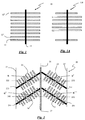
- the dimensions and dimensional ratios of the elements may not be correct and in some cases, such as for example in figure 1 the diameters of the spaced getter elements in the form of disks with respect to the central shaft diameter, have been altered in order to improve the figure comprehensibility.
- the getter pump envisions the presence of a plurality of getter cartridges, such as the one schematically represented in figure 1 , each getter cartridge 10 having a central shaft 11 acting as support and a plurality of spaced getter elements 12, 12',...12 n , typically and most preferably having the shape of disks.
- the means fixing the getter disks to the central shaft have not been shown since they are not necessary for the comprehension of the invention and within the knowledge of a person skilled in the art.
- an alternative getter cartridge 100 suitable to be used in getter pumps according to the present invention may have getter disks that are not equally spaced but there may be some gaps/voids at the extremities or within the disk stack and/or it may have some disks, typically the uppermost and lowermost ones, having a reduced diameter and/or an eccentric arrangement to facilitate the getter cartridge insertion/connection.
- a getter cartridge having the plurality of getter elements essentially equally spaced is just a preferred and non-limiting example of a suitable getter cartridge to be used in the pumps according to the present invention.
- the shaft 11 acting as support of the getter elements it is necessary for the shaft 11 acting as support of the getter elements to be linear, such as shown in figure 1 , in EP 0742370 , in EP 0753663 and in US 6149392 , while a configuration such as the one shown in WO 9858173 would not be suitable.
- the most useful shape for the linear shaft/support is cylindrical. Also, additional elements that may in some cases be present, such as additional thermal shields, are encompassed by the present invention.
- the invention is not limited to a specific getter material, but any suitable material capable to sorb gases by means of a thermal treatment may be employed and falls within the definition of getter materials for the scope and purposes of the present invention.
- getter materials for the scope and purposes of the present invention.
- the knowledge and characteristics of such materials are available to a person skilled in the art and may be easily retrieved from various sources, such as, for example, the above mentioned EP 0742370 .
- Particularly advantageous are getter metals or alloys comprising at least 30% of one or more of titanium, zirconium, yttrium.
- figure 2 shows a longitudinal cross-sectional view of a portion of a getter pump according to the present invention.
- the getter pump portion 20 has a cylindrical casing defined by two side walls 21 and 21', and its geometry is further defined by a revolution axis 26.
- Within the casing are contained four getter cartridges 22, 23, 24, 25, each with its own positioning plane 222, 232, 242, 252 orthogonal to the revolution axis 26 and intersecting the midpoint of the cartridge linear supports 221, 231, 241, 251.
- the angles formed by each positioning plane 222, 232, 242, 252 with each getter cartridge linear support 221, 231, 241, 251, are respectively indicated with ⁇ , ⁇ ', ⁇ " and ⁇ "'.
- the embodiment shown in figure 2 has two type of cartridges, 22 and 23 have disks of equal diameter while 24 and 25 have the disks closer to the side walls 21, 21' of the casing and to the connecting central vertical element 27 of reduced diameter and/or eccentrically arranged, in order to allow a better exploitation of the available space.
- This is just for exemplification of a suitable alternative, as in general it is more convenient, albeit not mandatory, that all the getter cartridges are equal to each other.
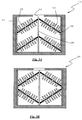
- the getter pump according to the present invention may be made by means of subassemblies integrated into a casing having the shape of a solid of revolution.
- This solution is outlined in the cross-sectional views of figures 3A and 3B .
- getter pump 310 has a casing 311 with an opening 312, containing an upper subassembly made up of two getter cartridges 314, 315 contained in a subcasing 316 acting as outer support for the getter cartridges which are also attached to an inner support 317.
- the outer support 316 may be attached and restrained to casing 311 by geometrical constraints only.
- FIG 3A two identical subassemblies are stacked with the same orientation, while pump 320 in figure 3B shows an alternative arrangement with the second subassembly turned upside down.
- pump 320 in figure 3B shows an alternative arrangement with the second subassembly turned upside down.
- elements having the same graphical representation and meaning have not been further described.
- getter cartridges suitable to be used in the getter pump structure according to the present invention, these have a linear central support whose length is preferably comprised between 4 and 30 cm, holding preferably between 2 and 7 getter disks per cm in the disk-holding portion.
- the number of getter cartridges placed in each pump may be usefully comprised between 2 and 100, more preferably between 4 and 25.
- the casing is closed at one end by a metallic base, usually made with the same material of the side wall, and at the other end by a standard vacuum flange; in this configuration the preferred embodiment envisions the presence of an inner connecting element, preferably placed in the center (i.e. coaxial with the revolution axis).
- the casing is defined only by the side wall, in this configuration the getter pump has an open-ended casing so that gas molecules can travel across the getter pump.
- This configuration is useful when the pump may be directly integrated in systems, for example coaxially, rather than being an additional element, as for example in the case of wall sections of particle accelerators that may be substituted with getter pumps according to the present invention, with a casing made according to the second preferred embodiment.
- This getter pump configuration allows the distribution of large sorption velocity and capacity inside the main section of a particle accelerator without interfering with any particle or electron beam moving through it.
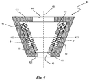
- the most preferred casing geometry is the truncated cone, with the getter cartridges following the cone inclination, i.e. the linear supporting element of the getter cartridge is parallel to the truncated cone walls.
- This embodiment of getter pump 40 is shown in the schematic cross-sectional view of figure 4 .
- Getter cartridges 42 and 43 are disposed with their linear supports 421, 431 lying parallel to the side walls 41, 41'.
- the casing has two openings, 44 and 45 for the gas flow and a revolution axis 46.
- angles ⁇ , ⁇ ' formed by positioning planes 422, 432 with the getter cartridge linear supports 421, 431 are comprised between 35° and 75°.
- This specific embodiment has the advantage of ensuing a better (quicker and more efficient) heating of the getter cartridge by the heat shielding action of the adjacent casing walls.
- angles formed by the getter positioning planes with the linear central supports of the cartridges are always intended as the acute angle formed by these two elements, as also represented in figure 2 ( ⁇ , ⁇ ', ⁇ ", ⁇ "') and figure 4 ( ⁇ , ⁇ ').
- getter pumps are most suitably used as stand-alone pumps, they can also be used in pumping systems coupled with other types of vacuum pumps, such as for example turbomolecular pumps, sputter ion pumps (SIP), cryopumps or other NEG (Non-Evaporable Getter) pumps.
- turbomolecular pumps such as for example turbomolecular pumps, sputter ion pumps (SIP), cryopumps or other NEG (Non-Evaporable Getter) pumps.
- SIP sputter ion pumps
- cryopumps such as for example cryopumps, or other NEG (Non-Evaporable Getter) pumps.
- NEG Non-Evaporable Getter
Landscapes
- Engineering & Computer Science (AREA)
- Mechanical Engineering (AREA)
- General Engineering & Computer Science (AREA)
- Manufacturing & Machinery (AREA)
- Compressors, Vaccum Pumps And Other Relevant Systems (AREA)
Applications Claiming Priority (2)
| Application Number | Priority Date | Filing Date | Title |
|---|---|---|---|
| ITMI20140595 | 2014-04-03 | ||
| PCT/IB2015/052174 WO2015150974A1 (en) | 2014-04-03 | 2015-03-25 | Getter pump |
Publications (2)
| Publication Number | Publication Date |
|---|---|
| EP2989327A1 EP2989327A1 (en) | 2016-03-02 |
| EP2989327B1 true EP2989327B1 (en) | 2016-09-07 |
Family
ID=50819846
Family Applications (1)
| Application Number | Title | Priority Date | Filing Date |
|---|---|---|---|
| EP15715853.6A Active EP2989327B1 (en) | 2014-04-03 | 2015-03-25 | Getter pump |
Country Status (9)
| Country | Link |
|---|---|
| US (1) | US9541078B2 (enExample) |
| EP (1) | EP2989327B1 (enExample) |
| JP (1) | JP6317471B2 (enExample) |
| KR (1) | KR101887292B1 (enExample) |
| CN (1) | CN106133314B (enExample) |
| ES (1) | ES2604969T3 (enExample) |
| RU (1) | RU2673834C2 (enExample) |
| TW (1) | TWI660125B (enExample) |
| WO (1) | WO2015150974A1 (enExample) |
Families Citing this family (6)
| Publication number | Priority date | Publication date | Assignee | Title |
|---|---|---|---|---|
| KR102154893B1 (ko) * | 2014-06-26 | 2020-09-11 | 사에스 게터스 에스.페.아. | 게터 펌핑 시스템 |
| RU2661493C1 (ru) * | 2017-07-24 | 2018-07-17 | ООО "Инновационные Вакуумные Решения" | Способ управления скоростью распыления материала в геттерном насосе и устройство геттерного насоса |
| RU187265U1 (ru) * | 2018-10-25 | 2019-02-27 | Закрытое акционерное общество "Время - Ч" | Комбинированный магниторазрядный геттерный насос для откачки вакуумных объемов рубидиевого стандарта частоты |
| CN114928934B (zh) * | 2022-06-20 | 2024-06-18 | 中国科学院近代物理研究所 | 加速器真空室非蒸散型吸气剂片固定装置及其使用方法 |
| EP4392673B1 (en) | 2022-08-01 | 2024-11-27 | Saes Getters S.p.A. | Snap-on getter pump assembly and its use |
| US20240337265A1 (en) * | 2023-04-06 | 2024-10-10 | Taiwan Semiconductor Manufacturing Company, Ltd. | Cryogenic pump for semiconductor processing |
Family Cites Families (14)
| Publication number | Priority date | Publication date | Assignee | Title |
|---|---|---|---|---|
| DE2034633C3 (de) | 1969-07-24 | 1979-10-25 | S.A.E.S. Getters S.P.A., Mailand (Italien) | Kartusche für eine Getterpumpe |
| US4137012A (en) * | 1976-11-03 | 1979-01-30 | S.A.E.S. Getters S.P.A. | Modular getter pumps |
| IT1255439B (it) * | 1992-07-17 | 1995-10-31 | Getters Spa | Pompa getter non evaporabile |
| US6109880A (en) * | 1994-10-31 | 2000-08-29 | Saes Pure Gas, Inc. | Getter pump module and system including focus shields |
| IT1274478B (it) * | 1995-05-11 | 1997-07-17 | Getters Spa | Insieme di riscaldamento per pompe getter e purificatori di gas |
| IT237018Y1 (it) * | 1995-07-10 | 2000-08-31 | Getters Spa | Pompa getter perfezionata in particolare per uno strumento dianalisi chimiche portatile |
| IT1292175B1 (it) * | 1997-06-17 | 1999-01-25 | Getters Spa | Pompa getter particolarmente adatta per l'uso a monte,in prossimita' e coassialmente ad una pompa turbomolecolare |
| IT1295340B1 (it) | 1997-10-15 | 1999-05-12 | Getters Spa | Pompa getter ad elevata velocita' di assorbimento di gas |
| IT1297013B1 (it) * | 1997-12-23 | 1999-08-03 | Getters Spa | Sistema getter per la purificazione dell'atmosfera di lavoro nei processi di deposizione fisica da vapore |
| US7045958B2 (en) * | 2003-04-14 | 2006-05-16 | Hewlett-Packard Development Company, L.P. | Vacuum device having a getter |
| ITMI20080282A1 (it) * | 2008-02-22 | 2009-08-23 | Getters Spa | Apparato per litografia con radiazione nell'uv estremo con un elemento assorbitore di idrocarburi comprendente un materiale getter |
| CN101978463B (zh) * | 2008-03-28 | 2013-02-13 | 工程吸气公司 | 包括吸气剂泵和离子泵的组合式抽气系统 |
| ITMI20090402A1 (it) * | 2009-03-17 | 2010-09-18 | Getters Spa | Sistema di pompaggio combinato comprendente una pompa getter ed una pompa ionica |
| ITMI20121732A1 (it) | 2012-10-15 | 2014-04-16 | Getters Spa | Pompa getter |
-
2015
- 2015-03-20 TW TW104108930A patent/TWI660125B/zh active
- 2015-03-25 ES ES15715853.6T patent/ES2604969T3/es active Active
- 2015-03-25 US US14/786,138 patent/US9541078B2/en active Active
- 2015-03-25 EP EP15715853.6A patent/EP2989327B1/en active Active
- 2015-03-25 RU RU2016143194A patent/RU2673834C2/ru active
- 2015-03-25 JP JP2016559888A patent/JP6317471B2/ja active Active
- 2015-03-25 CN CN201580017115.4A patent/CN106133314B/zh active Active
- 2015-03-25 WO PCT/IB2015/052174 patent/WO2015150974A1/en not_active Ceased
- 2015-03-25 KR KR1020167027026A patent/KR101887292B1/ko active Active
Also Published As
| Publication number | Publication date |
|---|---|
| US9541078B2 (en) | 2017-01-10 |
| TW201538855A (zh) | 2015-10-16 |
| KR101887292B1 (ko) | 2018-08-09 |
| EP2989327A1 (en) | 2016-03-02 |
| TWI660125B (zh) | 2019-05-21 |
| CN106133314B (zh) | 2017-09-22 |
| CN106133314A (zh) | 2016-11-16 |
| RU2016143194A (ru) | 2018-05-04 |
| JP6317471B2 (ja) | 2018-04-25 |
| ES2604969T3 (es) | 2017-03-10 |
| JP2017510748A (ja) | 2017-04-13 |
| US20160069337A1 (en) | 2016-03-10 |
| KR20160142299A (ko) | 2016-12-12 |
| RU2016143194A3 (enExample) | 2018-09-06 |
| WO2015150974A1 (en) | 2015-10-08 |
| RU2673834C2 (ru) | 2018-11-30 |
Similar Documents
| Publication | Publication Date | Title |
|---|---|---|
| EP2989327B1 (en) | Getter pump | |
| KR100302178B1 (ko) | 게터펌프및반도체공정장치 | |
| EP0910106B1 (en) | Getter pump with high velocity of gas sorption | |
| RU2495510C2 (ru) | Комбинированная насосная система, содержащая геттерный насос и ионный насос | |
| EP2791960B1 (en) | Getter pump | |
| JP6835592B2 (ja) | ゲッターポンプシステム | |
| ITMI20080250U1 (it) | Sistema di pompaggio combinato comprendente una pompa getter ed una pompa ionica | |
| Mullard Limited | Information from Mullard |
Legal Events
| Date | Code | Title | Description |
|---|---|---|---|
| PUAI | Public reference made under article 153(3) epc to a published international application that has entered the european phase |
Free format text: ORIGINAL CODE: 0009012 |
|
| 17P | Request for examination filed |
Effective date: 20151126 |
|
| AK | Designated contracting states |
Kind code of ref document: A1 Designated state(s): AL AT BE BG CH CY CZ DE DK EE ES FI FR GB GR HR HU IE IS IT LI LT LU LV MC MK MT NL NO PL PT RO RS SE SI SK SM TR |
|
| AX | Request for extension of the european patent |
Extension state: BA ME |
|
| GRAP | Despatch of communication of intention to grant a patent |
Free format text: ORIGINAL CODE: EPIDOSNIGR1 |
|
| DAV | Request for validation of the european patent (deleted) | ||
| DAX | Request for extension of the european patent (deleted) | ||
| INTG | Intention to grant announced |
Effective date: 20160405 |
|
| GRAS | Grant fee paid |
Free format text: ORIGINAL CODE: EPIDOSNIGR3 |
|
| GRAA | (expected) grant |
Free format text: ORIGINAL CODE: 0009210 |
|
| AK | Designated contracting states |
Kind code of ref document: B1 Designated state(s): AL AT BE BG CH CY CZ DE DK EE ES FI FR GB GR HR HU IE IS IT LI LT LU LV MC MK MT NL NO PL PT RO RS SE SI SK SM TR |
|
| REG | Reference to a national code |
Ref country code: GB Ref legal event code: FG4D |
|
| REG | Reference to a national code |
Ref country code: CH Ref legal event code: EP |
|
| REG | Reference to a national code |
Ref country code: IE Ref legal event code: FG4D |
|
| REG | Reference to a national code |
Ref country code: AT Ref legal event code: REF Ref document number: 827137 Country of ref document: AT Kind code of ref document: T Effective date: 20161015 |
|
| REG | Reference to a national code |
Ref country code: DE Ref legal event code: R096 Ref document number: 602015000291 Country of ref document: DE |
|
| REG | Reference to a national code |
Ref country code: CH Ref legal event code: NV Representative=s name: RENTSCH PARTNER AG, CH |
|
| REG | Reference to a national code |
Ref country code: LT Ref legal event code: MG4D |
|
| REG | Reference to a national code |
Ref country code: NL Ref legal event code: MP Effective date: 20160907 |
|
| PG25 | Lapsed in a contracting state [announced via postgrant information from national office to epo] |
Ref country code: RS Free format text: LAPSE BECAUSE OF FAILURE TO SUBMIT A TRANSLATION OF THE DESCRIPTION OR TO PAY THE FEE WITHIN THE PRESCRIBED TIME-LIMIT Effective date: 20160907 Ref country code: FI Free format text: LAPSE BECAUSE OF FAILURE TO SUBMIT A TRANSLATION OF THE DESCRIPTION OR TO PAY THE FEE WITHIN THE PRESCRIBED TIME-LIMIT Effective date: 20160907 Ref country code: NO Free format text: LAPSE BECAUSE OF FAILURE TO SUBMIT A TRANSLATION OF THE DESCRIPTION OR TO PAY THE FEE WITHIN THE PRESCRIBED TIME-LIMIT Effective date: 20161207 Ref country code: LT Free format text: LAPSE BECAUSE OF FAILURE TO SUBMIT A TRANSLATION OF THE DESCRIPTION OR TO PAY THE FEE WITHIN THE PRESCRIBED TIME-LIMIT Effective date: 20160907 Ref country code: HR Free format text: LAPSE BECAUSE OF FAILURE TO SUBMIT A TRANSLATION OF THE DESCRIPTION OR TO PAY THE FEE WITHIN THE PRESCRIBED TIME-LIMIT Effective date: 20160907 |
|
| REG | Reference to a national code |
Ref country code: AT Ref legal event code: MK05 Ref document number: 827137 Country of ref document: AT Kind code of ref document: T Effective date: 20160907 |
|
| PG25 | Lapsed in a contracting state [announced via postgrant information from national office to epo] |
Ref country code: LV Free format text: LAPSE BECAUSE OF FAILURE TO SUBMIT A TRANSLATION OF THE DESCRIPTION OR TO PAY THE FEE WITHIN THE PRESCRIBED TIME-LIMIT Effective date: 20160907 Ref country code: NL Free format text: LAPSE BECAUSE OF FAILURE TO SUBMIT A TRANSLATION OF THE DESCRIPTION OR TO PAY THE FEE WITHIN THE PRESCRIBED TIME-LIMIT Effective date: 20160907 Ref country code: GR Free format text: LAPSE BECAUSE OF FAILURE TO SUBMIT A TRANSLATION OF THE DESCRIPTION OR TO PAY THE FEE WITHIN THE PRESCRIBED TIME-LIMIT Effective date: 20161208 Ref country code: SE Free format text: LAPSE BECAUSE OF FAILURE TO SUBMIT A TRANSLATION OF THE DESCRIPTION OR TO PAY THE FEE WITHIN THE PRESCRIBED TIME-LIMIT Effective date: 20160907 |
|
| REG | Reference to a national code |
Ref country code: ES Ref legal event code: FG2A Ref document number: 2604969 Country of ref document: ES Kind code of ref document: T3 Effective date: 20170310 |
|
| REG | Reference to a national code |
Ref country code: FR Ref legal event code: PLFP Year of fee payment: 3 |
|
| PG25 | Lapsed in a contracting state [announced via postgrant information from national office to epo] |
Ref country code: EE Free format text: LAPSE BECAUSE OF FAILURE TO SUBMIT A TRANSLATION OF THE DESCRIPTION OR TO PAY THE FEE WITHIN THE PRESCRIBED TIME-LIMIT Effective date: 20160907 Ref country code: RO Free format text: LAPSE BECAUSE OF FAILURE TO SUBMIT A TRANSLATION OF THE DESCRIPTION OR TO PAY THE FEE WITHIN THE PRESCRIBED TIME-LIMIT Effective date: 20160907 |
|
| PG25 | Lapsed in a contracting state [announced via postgrant information from national office to epo] |
Ref country code: BE Free format text: LAPSE BECAUSE OF FAILURE TO SUBMIT A TRANSLATION OF THE DESCRIPTION OR TO PAY THE FEE WITHIN THE PRESCRIBED TIME-LIMIT Effective date: 20160907 Ref country code: BG Free format text: LAPSE BECAUSE OF FAILURE TO SUBMIT A TRANSLATION OF THE DESCRIPTION OR TO PAY THE FEE WITHIN THE PRESCRIBED TIME-LIMIT Effective date: 20161207 Ref country code: SK Free format text: LAPSE BECAUSE OF FAILURE TO SUBMIT A TRANSLATION OF THE DESCRIPTION OR TO PAY THE FEE WITHIN THE PRESCRIBED TIME-LIMIT Effective date: 20160907 Ref country code: SM Free format text: LAPSE BECAUSE OF FAILURE TO SUBMIT A TRANSLATION OF THE DESCRIPTION OR TO PAY THE FEE WITHIN THE PRESCRIBED TIME-LIMIT Effective date: 20160907 Ref country code: IS Free format text: LAPSE BECAUSE OF FAILURE TO SUBMIT A TRANSLATION OF THE DESCRIPTION OR TO PAY THE FEE WITHIN THE PRESCRIBED TIME-LIMIT Effective date: 20170107 Ref country code: AT Free format text: LAPSE BECAUSE OF FAILURE TO SUBMIT A TRANSLATION OF THE DESCRIPTION OR TO PAY THE FEE WITHIN THE PRESCRIBED TIME-LIMIT Effective date: 20160907 Ref country code: CZ Free format text: LAPSE BECAUSE OF FAILURE TO SUBMIT A TRANSLATION OF THE DESCRIPTION OR TO PAY THE FEE WITHIN THE PRESCRIBED TIME-LIMIT Effective date: 20160907 Ref country code: PT Free format text: LAPSE BECAUSE OF FAILURE TO SUBMIT A TRANSLATION OF THE DESCRIPTION OR TO PAY THE FEE WITHIN THE PRESCRIBED TIME-LIMIT Effective date: 20170109 Ref country code: PL Free format text: LAPSE BECAUSE OF FAILURE TO SUBMIT A TRANSLATION OF THE DESCRIPTION OR TO PAY THE FEE WITHIN THE PRESCRIBED TIME-LIMIT Effective date: 20160907 |
|
| REG | Reference to a national code |
Ref country code: DE Ref legal event code: R097 Ref document number: 602015000291 Country of ref document: DE |
|
| PLBE | No opposition filed within time limit |
Free format text: ORIGINAL CODE: 0009261 |
|
| STAA | Information on the status of an ep patent application or granted ep patent |
Free format text: STATUS: NO OPPOSITION FILED WITHIN TIME LIMIT |
|
| PG25 | Lapsed in a contracting state [announced via postgrant information from national office to epo] |
Ref country code: DK Free format text: LAPSE BECAUSE OF FAILURE TO SUBMIT A TRANSLATION OF THE DESCRIPTION OR TO PAY THE FEE WITHIN THE PRESCRIBED TIME-LIMIT Effective date: 20160907 |
|
| 26N | No opposition filed |
Effective date: 20170608 |
|
| PG25 | Lapsed in a contracting state [announced via postgrant information from national office to epo] |
Ref country code: SI Free format text: LAPSE BECAUSE OF FAILURE TO SUBMIT A TRANSLATION OF THE DESCRIPTION OR TO PAY THE FEE WITHIN THE PRESCRIBED TIME-LIMIT Effective date: 20160907 |
|
| REG | Reference to a national code |
Ref country code: CH Ref legal event code: PCAR Free format text: NEW ADDRESS: BELLERIVESTRASSE 203 POSTFACH, 8034 ZUERICH (CH) |
|
| PG25 | Lapsed in a contracting state [announced via postgrant information from national office to epo] |
Ref country code: MC Free format text: LAPSE BECAUSE OF FAILURE TO SUBMIT A TRANSLATION OF THE DESCRIPTION OR TO PAY THE FEE WITHIN THE PRESCRIBED TIME-LIMIT Effective date: 20160907 |
|
| REG | Reference to a national code |
Ref country code: IE Ref legal event code: MM4A |
|
| PG25 | Lapsed in a contracting state [announced via postgrant information from national office to epo] |
Ref country code: LU Free format text: LAPSE BECAUSE OF NON-PAYMENT OF DUE FEES Effective date: 20170325 |
|
| PG25 | Lapsed in a contracting state [announced via postgrant information from national office to epo] |
Ref country code: IE Free format text: LAPSE BECAUSE OF NON-PAYMENT OF DUE FEES Effective date: 20170325 |
|
| REG | Reference to a national code |
Ref country code: FR Ref legal event code: PLFP Year of fee payment: 4 |
|
| PG25 | Lapsed in a contracting state [announced via postgrant information from national office to epo] |
Ref country code: MT Free format text: LAPSE BECAUSE OF NON-PAYMENT OF DUE FEES Effective date: 20170325 |
|
| PG25 | Lapsed in a contracting state [announced via postgrant information from national office to epo] |
Ref country code: AL Free format text: LAPSE BECAUSE OF FAILURE TO SUBMIT A TRANSLATION OF THE DESCRIPTION OR TO PAY THE FEE WITHIN THE PRESCRIBED TIME-LIMIT Effective date: 20160907 |
|
| PG25 | Lapsed in a contracting state [announced via postgrant information from national office to epo] |
Ref country code: HU Free format text: LAPSE BECAUSE OF FAILURE TO SUBMIT A TRANSLATION OF THE DESCRIPTION OR TO PAY THE FEE WITHIN THE PRESCRIBED TIME-LIMIT; INVALID AB INITIO Effective date: 20150325 |
|
| PG25 | Lapsed in a contracting state [announced via postgrant information from national office to epo] |
Ref country code: CY Free format text: LAPSE BECAUSE OF FAILURE TO SUBMIT A TRANSLATION OF THE DESCRIPTION OR TO PAY THE FEE WITHIN THE PRESCRIBED TIME-LIMIT Effective date: 20160907 |
|
| PG25 | Lapsed in a contracting state [announced via postgrant information from national office to epo] |
Ref country code: MK Free format text: LAPSE BECAUSE OF FAILURE TO SUBMIT A TRANSLATION OF THE DESCRIPTION OR TO PAY THE FEE WITHIN THE PRESCRIBED TIME-LIMIT Effective date: 20160907 |
|
| P01 | Opt-out of the competence of the unified patent court (upc) registered |
Effective date: 20230515 |
|
| PGFP | Annual fee paid to national office [announced via postgrant information from national office to epo] |
Ref country code: ES Payment date: 20250416 Year of fee payment: 11 |
|
| PGFP | Annual fee paid to national office [announced via postgrant information from national office to epo] |
Ref country code: IT Payment date: 20250331 Year of fee payment: 11 |
|
| PGFP | Annual fee paid to national office [announced via postgrant information from national office to epo] |
Ref country code: CH Payment date: 20250401 Year of fee payment: 11 |
|
| REG | Reference to a national code |
Ref country code: CH Ref legal event code: U11 Free format text: ST27 STATUS EVENT CODE: U-0-0-U10-U11 (AS PROVIDED BY THE NATIONAL OFFICE) Effective date: 20260401 |
|
| PGFP | Annual fee paid to national office [announced via postgrant information from national office to epo] |
Ref country code: GB Payment date: 20260324 Year of fee payment: 12 |
|
| PGFP | Annual fee paid to national office [announced via postgrant information from national office to epo] |
Ref country code: DE Payment date: 20260320 Year of fee payment: 12 |
|
| PGFP | Annual fee paid to national office [announced via postgrant information from national office to epo] |
Ref country code: FR Payment date: 20260324 Year of fee payment: 12 |
|
| PGFP | Annual fee paid to national office [announced via postgrant information from national office to epo] |
Ref country code: TR Payment date: 20260324 Year of fee payment: 12 |