EP2988982B1 - Tragestruktur eines schienenfahrzeugs - Google Patents
Tragestruktur eines schienenfahrzeugs Download PDFInfo
- Publication number
- EP2988982B1 EP2988982B1 EP14720927.4A EP14720927A EP2988982B1 EP 2988982 B1 EP2988982 B1 EP 2988982B1 EP 14720927 A EP14720927 A EP 14720927A EP 2988982 B1 EP2988982 B1 EP 2988982B1
- Authority
- EP
- European Patent Office
- Prior art keywords
- coupling element
- support structure
- car body
- lifting
- rail vehicle
- Prior art date
- Legal status (The legal status is an assumption and is not a legal conclusion. Google has not performed a legal analysis and makes no representation as to the accuracy of the status listed.)
- Active
Links
- 230000008878 coupling Effects 0.000 claims description 93
- 238000010168 coupling process Methods 0.000 claims description 93
- 238000005859 coupling reaction Methods 0.000 claims description 93
- 238000000034 method Methods 0.000 claims description 9
- 239000000725 suspension Substances 0.000 claims description 2
- 239000012530 fluid Substances 0.000 description 13
- 239000013589 supplement Substances 0.000 description 2
- 230000008901 benefit Effects 0.000 description 1
- 230000015572 biosynthetic process Effects 0.000 description 1
- 208000028755 loss of height Diseases 0.000 description 1
- 238000010248 power generation Methods 0.000 description 1
- 230000008569 process Effects 0.000 description 1
- 230000009467 reduction Effects 0.000 description 1
- 239000007787 solid Substances 0.000 description 1
- 230000007704 transition Effects 0.000 description 1
Images


Classifications
-
- B—PERFORMING OPERATIONS; TRANSPORTING
- B61—RAILWAYS
- B61F—RAIL VEHICLE SUSPENSIONS, e.g. UNDERFRAMES, BOGIES OR ARRANGEMENTS OF WHEEL AXLES; RAIL VEHICLES FOR USE ON TRACKS OF DIFFERENT WIDTH; PREVENTING DERAILING OF RAIL VEHICLES; WHEEL GUARDS, OBSTRUCTION REMOVERS OR THE LIKE FOR RAIL VEHICLES
- B61F1/00—Underframes
- B61F1/08—Details
- B61F1/14—Attaching or supporting vehicle body-structure
-
- B—PERFORMING OPERATIONS; TRANSPORTING
- B61—RAILWAYS
- B61F—RAIL VEHICLE SUSPENSIONS, e.g. UNDERFRAMES, BOGIES OR ARRANGEMENTS OF WHEEL AXLES; RAIL VEHICLES FOR USE ON TRACKS OF DIFFERENT WIDTH; PREVENTING DERAILING OF RAIL VEHICLES; WHEEL GUARDS, OBSTRUCTION REMOVERS OR THE LIKE FOR RAIL VEHICLES
- B61F5/00—Constructional details of bogies; Connections between bogies and vehicle underframes; Arrangements or devices for adjusting or allowing self-adjustment of wheel axles or bogies when rounding curves
- B61F5/02—Arrangements permitting limited transverse relative movements between vehicle underframe or bolster and bogie; Connections between underframes and bogies
-
- B—PERFORMING OPERATIONS; TRANSPORTING
- B61—RAILWAYS
- B61F—RAIL VEHICLE SUSPENSIONS, e.g. UNDERFRAMES, BOGIES OR ARRANGEMENTS OF WHEEL AXLES; RAIL VEHICLES FOR USE ON TRACKS OF DIFFERENT WIDTH; PREVENTING DERAILING OF RAIL VEHICLES; WHEEL GUARDS, OBSTRUCTION REMOVERS OR THE LIKE FOR RAIL VEHICLES
- B61F5/00—Constructional details of bogies; Connections between bogies and vehicle underframes; Arrangements or devices for adjusting or allowing self-adjustment of wheel axles or bogies when rounding curves
- B61F5/02—Arrangements permitting limited transverse relative movements between vehicle underframe or bolster and bogie; Connections between underframes and bogies
- B61F5/14—Side bearings
Definitions
- the invention relates to a method according to the preamble of claim 1.
- wheel wear leads to a reduction in the height of the body.
- the inserts are installed according to the state of the art by means of stationary or mobile lifting systems or by means of cranes which are supported on the ground.
- the car body is raised by means of the lifting systems until the coupling element is completely relieved of force.
- the weight of the car body is transferred directly to the surface.
- the inserts can be placed under or over the force-relieved coupling element can be inserted. This requires an appropriate workshop infrastructure or expensive mobile lifting systems.
- a known method for replacing a secondary suspension is in the BE 903 050 A shown.
- the invention has for its object to provide a method by means of which coupling elements can be added without great effort.
- a lifting device will be supported on the support element, by means of which the car body is raised with respect to the ground. Supplements can be inserted into a gap that forms between the coupling element and the support structure or between the support structure and the car body.
- the inserts can also be installed at locations that do not have a solid subsurface, for example on a ballasted track section, since the lifting device is not supported on the subsurface.
- no workshop infrastructure with expensive lifting systems is required to carry out the assembly of the inserts.
- the invention therefore provides a method by means of which coupling elements can be added without great effort and without the need for a complex workshop infrastructure.
- the coupling element has a longitudinal axis, the support element being arranged coaxially to this longitudinal axis in a preferred embodiment of the support structure.
- the part of the support structure below the connection which is designed as a support element, is, in a special embodiment, a balcony-shaped shape of the support structure.
- the part of the support structure below the connection which is designed as a support element, is designed as a thread of a bore in the support structure.
- the bore in the support structure can be designed as a continuous bore through the support structure or as a blind bore.
- a lifting device can be supported or supported on the support element.
- the lifting device can be arranged, for example, in the blind bore or in the bore in the support structure or between the coupling element and the car body or in the coupling element or in a lower region of the car body.
- the lifting device can also be arranged permanently at the positions mentioned.
- a hydraulic or a mechanical or an electrical or a pneumatic drive unit for power generation can comprise.
- the mechanical drive unit can be designed as a spindle and the hydraulic drive unit can, for example, be designed as a piston of a hydraulic cylinder.
- the coupling element is preferably a secondary spring of the rail vehicle.
- the secondary spring supports the car body on the support structure.
- the secondary spring can be designed as a hydraulic spring, as a coil spring or as an air spring.
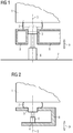
- FIG. 1 shows an example and schematically a section through a support structure 8 according to the prior art.
- a section of a support structure 8 of a rail vehicle is shown, on which a car body 1 is supported by means of a coupling element 2.
- the coupling element 2 is connected to the support structure 8 by means of a positive and / or non-positive connection 3.
- the connection 3 is provided by the interface between the lower, peg-shaped part of the coupling element 2 and the vertically oriented sub-surface of the support structure 8, which abuts the peg-shaped part of the coupling element 2.
- To insert the coupling element 2, the coupling element 2, together with the car body 1, is raised by means of a lifting device 6.
- the raised coupling element 2 is in FIG. 1 dashed shown.
- the coupling element 2 When the coupling element 2 is raised, the car body 1 is also raised. There is a gap 12 between the coupling element 2 and the support structure 8. An insert is inserted into this gap 12, then the coupling element 2 is lowered again together with the car body 1.
- the directions 9 of lifting and lowering are oriented parallel to a longitudinal axis 5 of the coupling element 2.
- the lifting device 6 is supported on the ground 7 during the lifting and lowering of the coupling element 2.
- FIG 2 shows an example and schematically a section through a support structure 8 according to the invention with a balcony-shaped shape of the support structure 8.
- a detail of a support structure 8 of a rail vehicle is shown, on which a car body 1 is supported by means of a coupling element 2.
- the coupling element 2 is connected to the support structure 8 by means of a positive and / or non-positive connection 3.
- the connection 3 is provided by the interface between the lower, peg-shaped part of the coupling element 2 and the vertically oriented sub-surface of the support structure 8, which abuts the peg-shaped part of the coupling element 2.
- the coupling element 2 is raised by means of the lifting device 6, together with the car body 1. This creates, accordingly FIG.
- FIG 2 an in FIG 2 for reasons of clarity not shown gap 12 between the coupling element 2 and the support structure 8.
- this gap 12 an insert is inserted, then the coupling element 2 is lowered again together with the car body 1.
- a part of the support structure 8 below the connection 3 is designed as a support element 4.
- the lifting device 6 is supported in the directions 9 during the lifting and lowering.
- FIG 3 shows an example and schematically a section through a support structure 8 according to the invention with a blind bore in the support structure 8.
- a section of a support structure 8 of a rail vehicle is shown, on which a car body 1 is supported by means of a coupling element 2.
- the coupling element 2 is connected to the support structure 8 by means of a positive and / or non-positive connection 3.
- the connection 3 is provided by the interface between the lower, peg-shaped part of the coupling element 2 and the vertically oriented sub-surface of the support structure 8, which abuts the peg-shaped part of the coupling element 2.
- the coupling element 2 together with the car body 1 is raised by means of a lifting device 6.
- a part of the support structure 8 below the connection 3, specifically the limitation of the blind hole in the support structure 8, is designed as a support element 4.
- the blind bore is filled with a fluid 11. If fluid 11 is pumped into the blind bore, the coupling element 2 is raised. If fluid 11 is drained from the blind bore, the coupling element 2 is lowered.
- FIG. 1 an in FIG 3 for reasons of clarity not shown gap 12 between the coupling element 2 and the support structure 8.
- An insert is inserted into this gap 12, then the coupling element 2 is lowered again together with the car body 1.
- the directions 9 of lifting and lowering are oriented parallel to a longitudinal axis 5 of the coupling element.
- FIG 4 shows an example and schematically a section through a support structure according to the invention with a bore through the support structure 8.
- a detail of a support structure 8 of a rail vehicle is shown, on which a car body 1 is supported by means of a coupling element 2.
- the coupling element 2 is connected to the support structure 8 by means of a positive and / or non-positive connection 3.
- the connection 3 is through the interface between the lower, peg-shaped part of the coupling element 2 and the vertically oriented partial surface of the support structure 8, which rests on the pin-shaped part of the coupling element 2.
- To insert the coupling element 2, the coupling element 2, together with the car body 1, is raised by means of a lifting device 6. By lifting the coupling element 2, together with the car body 1, accordingly FIG.
- FIG 4 an in FIG 4 for reasons of clarity not shown gap 12 between the coupling element 2 and the support structure 8.
- An insert is inserted into this gap 12, then the coupling element 2, together with the car body 1, is lowered again.
- the directions 9 of lifting and lowering are oriented parallel to a longitudinal axis 5 of the coupling element.
- the lifting device 6 is designed in the embodiment shown as a spindle.
- the part of the support structure 8, which is designed as a support element 4, is a thread, which is arranged below the connection 3.
- Rotation of the spindle in the directions of rotation 10 brings about a translational movement of the spindle in the directions 9, which movement is oriented parallel to the longitudinal axis 5 of the coupling element, as a result of which, depending on the direction of rotation 10, either the coupling element 2 and the body 1 are raised or lowered.
- FIG 5 shows an example and schematically a section through a support structure 8 according to the invention with a pin fixed to the support structure 8.
- a section of a support structure 8 of a rail vehicle is shown, on which a car body 1 is supported by means of a coupling element 2.
- the coupling element 2 is connected to the support structure 8 by means of a positive and / or non-positive connection 3.
- the connection 3 is provided by the interface between the vertically oriented outer surface of the pin of the support structure 8 and the inner vertically oriented partial surface of the coupling element 2, which lies against the vertically oriented outer surface of the pin.
- a lifting device 6 which is designed here as a hydraulic lifting device 6.
- the space enclosed by the coupling element 2 and the end face of the pin is filled with a fluid 11. If fluid 11 is pumped into this space, the coupling element 2 is raised. If fluid 11 is drained from the room, the coupling element 2 is lowered.
- the raised coupling element 2 is indicated by the dashed line. An insert is inserted into this gap 12, then the coupling element 2 is lowered again together with the car body 1.
- the directions 9 of lifting and lowering are oriented parallel to a longitudinal axis 5 of the coupling element.
- FIG 6 shows an example and schematically a section through a support structure 8 according to the invention with a lifting device 6 arranged in the car body 1.
- a section of a support structure 8 of a rail vehicle is shown, on which a car body 1 is supported by means of a coupling element 2.
- the coupling element 2 is connected to the support structure 8 by means of a positive and / or non-positive connection 3.
- the connection 3 is provided by the interface between the lower, peg-shaped part of the coupling element 2 and the vertically oriented sub-surface of the support structure 8, which abuts the peg-shaped part of the coupling element 2.
- the upper part of the support structure 8 is designed as a traverse. On the traverse is similar to that in FIG 5 shown, a pin fixed.
- the space enclosed by the car body 1 and by the pin fixed to the crossmember is filled with a fluid 11 and forms the lifting device 6.
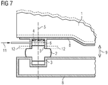
- FIG 7 shows, by way of example and schematically, a section through a carrying structure 8 according to the invention with a lifting device 6 arranged between the coupling element 2 and the car body 1.
- the upper part of the carrying structure 8 is designed as a traverse, the car body 1 by means of the coupling element 2 on the lower part of the carrying structure 8 is supported.
- a surface which delimits the coupling element 2 upwards is designed as a support element 4, on which the lifting device 6 is supported.
- the coupling element 2 is connected to the support structure 8 on both sides by means of a positive and / or non-positive connection 3.
- connection 3 is on the one hand through the interface between the lower, cone-shaped part of the coupling element 2 and the vertically oriented partial surface of the support structure 8, which rests on the cone-shaped part of the coupling element 2, and on the other hand through the interface between the upper, cone-shaped part of the coupling element 2 and the vertically oriented partial area of the traverse.
- the space formed by the vertically oriented partial surface of the cross member and the upper, peg-shaped part of the coupling element 2 is filled with a fluid 11 and forms the lifting device 6. If fluid 11 is pumped into this space, the car body 1 , together with the traverse, raised in relation to the coupling element 2.
- the car body 1 or the traverse is lowered.
- By lifting the car body 1 or the cross member creates a gap 12 between the coupling element 2 and the end face of the vertically oriented partial surface of the cross member.
- the raised car body 1 is indicated by the dashed line.
- An insert is inserted into this gap 12, then the car body 1 or the cross member is lowered again.
- the directions 9 of lifting and lowering are oriented parallel to a longitudinal axis 5 of the coupling element.
- the carrying structure 8 according to the invention is designed such that the weight of the car body 1 is always supported directly or indirectly on the carrying structure 8 during the lifting and lowering of the car body 1.
- the coupling element 2 can thus be inserted at any location of the rail vehicle with little effort.
Landscapes
- Engineering & Computer Science (AREA)
- Mechanical Engineering (AREA)
- Vehicle Cleaning, Maintenance, Repair, Refitting, And Outriggers (AREA)
- Handcart (AREA)
- Fittings On The Vehicle Exterior For Carrying Loads, And Devices For Holding Or Mounting Articles (AREA)
- Bridges Or Land Bridges (AREA)
- Aiming, Guidance, Guns With A Light Source, Armor, Camouflage, And Targets (AREA)
Description
- Die Erfindung betrifft ein Verfahren nach dem Oberbegriff von Anspruch 1.
- Bei Schienenfahrzeugen führt der Radverschleiß zu einer Reduktion der Höhe der Lage des Wagenkastens.
- Bei Einfahrten des Schienenfahrzeugs in eine Station kann es daher vorkommen, dass das Niveau eines in dem Wagenkasten angeordneten Fußbodens unter dem Fußbodenniveau der Station zu liegen kommt. Durch den Niveauunterschied zwischen der Station und der Fußbodenoberkante des Wagenkastens kann es zur Bildung einer Stufe im Übergangsbereich zwischen dem im Wagenkasten angeordneten Fußboden und dem Fußboden der Station kommen. Diese Stufen stellen ein beträchtliches Sicherheitsrisiko für Passagiere dar, daher wird der durch den Radverschleiß hervorgerufene Höhenverlust nach dem Stand der Technik dadurch ausgeglichen, dass der Wagenkasten gegenüber seiner Tragestruktur angehoben wird. Dazu werden unter oder über die den Wagenkasten abstützenden Koppelelemente sogenannte Beilagen eingelegt. Diesen Vorgang nennt man Beilegen eines Koppelelements.
- Die Montage der Beilagen erfolgt nach dem Stand der Technik mittels stationärer oder mobiler Hubanlagen beziehungsweise mittels Kränen, welche am Untergrund abgestützt sind. Dabei wird der Wagenkasten mittels der Hubanlagen soweit angehoben, bis das Koppelelement vollständig kraftentlastet ist. Das Gewicht des Wagenkastens wird dabei direkt auf den Untergrund übertragen. Danach können die Beilagen unter oder über das kraftentlastete Koppelelement eingelegt werden. Dazu ist eine entsprechende Werkstätteninfrastruktur beziehungsweise sind teure mobile Hubanlagen notwendig.
- Da die Hubanlagen am Untergrund abgestützt sind, ist ein fester und vorzugsweise glatter Untergrund notwendig, welcher den auftretenden Belastungen durch das Gewicht des Schienenfahrzeugs standhält.
- Deshalb kann die Montage der Beilagen oftmals nur in einer Werkstätte mit entsprechender Werkstätteninfrastruktur durchgeführt werden. Dies ist mit erheblichem Aufwand verbunden.
- Aus der
DE-A-43 11 521 ist ein Verfahren zur Regelung der Querneigung eines Wagenkastens bekannt,, wobei mittels Hebevorrichtung der Wagenkasten angehoben wird. - Ein bekanntes Verfahren zum Austausch einer Sekundärfederung ist in der
BE 903 050 A - Der Erfindung liegt die Aufgabe zugrunde, ein Verfahren bereitzustellen, mittels welchem Koppelelemente ohne großen Aufwand beigelegt werden können.
- Erfindungsgemäß geschieht dies mit einem Verfahren gemäß Anspruch 1.
- Am Abstützelement wird eine Hebevorrichtung abgestützt werden, mittels der der Wagenkasten in Bezug auf den Untergrundangehoben wird. In einen sich dabei ausbildenden Spalt zwischen dem Koppelelement und der Tragestruktur oder zwischen der Tragestruktur und dem Wagenkasten können Beilagen eingelegt werden.
- Damit kann, im Gegensatz zum Stand der Technik, die Montage der Beilagen auch an Orten durchgeführt werden, die keinen festen Untergrund aufweisen, beispielsweise auf einem eingeschotterten Gleisabschnitt, da die Hebevorrichtung nicht am Untergrund abgestützt ist. Es ist außerdem keine Werkstattinfrastruktur mit teuren Hubanlagen nötig, um die Montage der Beilagen durchzuführen.
- Die Erfindung stellt daher ein Verfahren bereit, mittels welchem Koppelelemente ohne großen Aufwand und ohne Notwendigkeit einer aufwändigen Werkstätteninfrastruktur beigelegt werden können.
- Das Koppelelement weist eine Längsachse auf, wobei in einer bevorzugten Ausführungsform der Tragestruktur das Abstützelement koaxial zu dieser Längsachse angeordnet ist.
- Der Teil der Tragestruktur unterhalb der Verbindung, welcher als Abstützelement ausgebildet ist, ist in einer speziellen Ausführungsform eine balkonförmige Ausformung der Tragestruktur.
- Der Teil der Tragestruktur unterhalb des Verbindung, welcher als Abstützelement ausgebildet ist, ist in einer weiteren Ausführungsform die Begrenzung einer Sackbohrung in der Tragestruktur.
- In einer anderen Ausführungsform der erfindungsgemäßen Tragestruktur ist der Teil der Tragestruktur unterhalb der Verbindung, welcher als Abstützelement ausgebildet ist, als Gewinde einer Bohrung in der Tragestruktur ausgeführt.
- Die Bohrung in der Tragestruktur kann als durchgängige Bohrung durch die Tragestruktur oder als Sackbohrung ausgeführt sein.
- Am Abstützelement ist eine Hebevorrichtung abstützbar oder abgestützt.
- Als nicht beanspruchtes Merkmal kann die Hebevorrichtung beispielsweise in der Sackbohrung oder in der Bohrung in der Tragestruktur oder zwischen dem Koppelelement und dem Wagenkasten oder im Koppelelement oder in einem unteren Bereich des Wagenkastens angeordnet werden. Die Hebevorrichtung kann auch permanent an den genannten Positionen angeordnet sein.
- Damit ergibt sich der Vorteil, dass das Beilegen des Koppelelements an jedem beliebigen Standort des Schienenfahrzeugs durchgeführt werden kann.
- Ebenso als nicht beanspruchtes Merkmal kann eine hydraulische oder eine mechanische oder eine elektrische oder eine pneumatische Antriebseinheit zur Krafterzeugung umfassen.
- Beispielsweise kann die mechanische Antriebseinheit als Spindel ausgeführt sein und die hydraulische Antriebseinheit kann beispielsweise als Kolben eines Hydraulikzylinders ausgeführt sein.
- Das Koppelelement ist vorzugsweise eine Sekundärfeder des Schienenfahrzeugs. Die Sekundärfeder stützt den Wagenkasten an der Tragestruktur ab.
- Die Sekundärfeder kann als hydraulische Feder, als Schraubenfeder oder als Luftfeder ausgebildet sein.
-
-
FIG 1 zeigt beispielhaft und schematisch einen Schnitt durch eine Tragestruktur nach dem Stand der Technik. -
FIG 2 zeigt beispielhaft und schematisch einen Schnitt durch eine erfindungsgemäße Tragestruktur mit einer balkonförmigen Ausformung der Tragestruktur. -
FIG 3 zeigt beispielhaft und schematisch einen Schnitt durch eine erfindungsgemäße Tragestruktur mit einer Sackbohrung in der Tragestruktur. -
FIG 4 zeigt beispielhaft und schematisch einen Schnitt durch eine erfindungsgemäße Tragestruktur mit einer Bohrung durch die Tragestruktur. -
FIG 5 zeigt beispielhaft und schematisch einen Schnitt durch eine erfindungsgemäße Tragestruktur mit einem an der Tragestruktur fixierten Zapfen. -
FIG 6 zeigt beispielhaft und schematisch einen Schnitt durch eine erfindungsgemäße Tragestruktur mit einer im Wagenkasten angeordneten Hebevorrichtung. -
FIG 7 zeigt beispielhaft und schematisch einen Schnitt durch eine erfindungsgemäße Tragestruktur mit einer zwischen dem Koppelelement und dem Wagenkasten angeordneten Hebevorrichtung. -
FIG 1 zeigt beispielhaft und schematisch einen Schnitt durch eine Tragestruktur 8 nach dem Stand der Technik. Dargestellt ist ein Ausschnitt einer Tragestruktur 8 eines Schienenfahrzeuges, auf dem ein Wagenkasten 1 mittels eines Koppelelements 2 abgestützt ist. Das Koppelelement 2 ist mit der Tragestruktur 8 mittels einer formschlüssigen und/oder kraftschlüssigen Verbindung 3 verbunden. Die Verbindung 3 ist durch die Grenzfläche zwischen dem unteren, zapfenförmig ausgebildeten Teil des Koppelelements 2 und der vertikal orientierten Teilfläche der Tragestruktur 8, welche am zapfenförmig ausgebildeten Teil des Koppelelements 2 anliegt, gegeben. Zum Beilegen des Koppelelements 2 wird das Koppelelement 2, zusammen mit dem Wagenkasten 1, mittels einer Hebevorrichtung 6 angehoben. Das angehobene Koppelelement 2 ist inFIG 1 gestrichelt dargestellt. Mit dem Anheben des Koppelelements 2 wird auch der Wagenkasten 1 angehoben.
Es entsteht ein Spalt 12 zwischen dem Koppelelement 2 und der Tragestruktur 8. In diesen Spalt 12 wird eine Beilage eingelegt, anschließend wird das Koppelelement 2 zusammen mit dem Wagenkasten 1 wieder abgesenkt. Die Richtungen 9 des Anhebens und des Absenkens sind parallel zu einer Längsachse 5 des Koppelelements 2 orientiert. Die Hebevorrichtung 6 stützt sich während des Anhebens und des Absenkens des Koppelelements 2 am Untergrund 7 ab. -
FIG 2 zeigt beispielhaft und schematisch einen Schnitt durch eine erfindungsgemäße Tragestruktur 8 mit einer balkonförmigen Ausformung der Tragestruktur 8. Dargestellt ist ein Ausschnitt einer Tragestruktur 8 eines Schienenfahrzeuges, auf dem ein Wagenkasten 1 mittels eines Koppelelements 2 abgestützt ist. Das Koppelelement 2 ist mit der Tragestruktur 8 mittels einer formschlüssigen und/oder kraftschlüssigen Verbindung 3 verbunden. Die Verbindung 3 ist durch die Grenzfläche zwischen dem unteren, zapfenförmig ausgebildeten Teil des Koppelelements 2 und der vertikal orientierten Teilfläche der Tragestruktur 8, welche am zapfenförmig ausgebildeten Teil des Koppelelements 2 anliegt, gegeben. Zum Beilegen des Koppelelements 2 wird das Koppelelement 2 mittels der Hebevorrichtung 6, zusammen mit dem Wagenkasten 1, angehoben. Dadurch entsteht, entsprechendFIG 1 , ein inFIG 2 aus Übersichtsgründen nicht dargestellter Spalt 12 zwischen dem Koppelelement 2 und der Tragestruktur 8. In diesen Spalt 12 wird eine Beilage eingelegt, anschließend wird das Koppelelement 2 zusammen mit dem Wagenkasten 1 wieder abgesenkt. Ein Teil der Tragestruktur 8 unterhalb der Verbindung 3 ist als Abstützelement 4 ausgebildet. An der Stelle, an der die Tragestruktur 8 als Abstützelement 4 ausgebildet ist, ist die Hebevorrichtung 6 während des Anhebens und Absenkens in die Richtungen 9 abgestützt. -
FIG 3 zeigt beispielhaft und schematisch einen Schnitt durch eine erfindungsgemäße Tragestruktur 8 mit einer Sackbohrung in der Tragestruktur 8. Dargestellt ist ein Ausschnitt einer Tragestruktur 8 eines Schienenfahrzeuges, auf dem ein Wagenkasten 1 mittels eines Koppelelements 2 abgestützt ist. Das Koppelelement 2 ist mit der Tragestruktur 8 mittels einer formschlüssigen und/oder kraftschlüssigen Verbindung 3 verbunden. Die Verbindung 3 ist durch die Grenzfläche zwischen dem unteren, zapfenförmig ausgebildeten Teil des Koppelelements 2 und der vertikal orientierten Teilfläche der Tragestruktur 8, welche am zapfenförmig ausgebildeten Teil des Koppelelements 2 anliegt, gegeben. Zum Beilegen des Koppelelements 2 wird das Koppelelement 2, zusammen mit dem Wagenkasten 1, mittels einer Hebevorrichtung 6 angehoben. Ein Teil der Tragestruktur 8 unterhalb der Verbindung 3, konkret die Begrenzung der Sackbohrung in der Tragestruktur 8, ist als Abstützelement 4 ausgebildet. In der dargestellten Ausführungsform ist die Sackbohrung mit einem Fluid 11 gefüllt. Wird Fluid 11 in die Sackbohrung gepumpt, so wird das Koppelelement 2 angehoben. Wird Fluid 11 aus der Sackbohrung abgelassen, so wird das Koppelelement 2 abgesenkt. Durch das Anheben des Koppelelements 2, zusammen mit dem Wagenkasten 1, entsteht, entsprechendFIG 1 , ein inFIG 3 aus Übersichtlichkeitsgründen nicht dargestellter Spalt 12 zwischen dem Koppelelement 2 und der Tragestruktur 8. In diesen Spalt 12 wird eine Beilage eingelegt, anschließend wird das Koppelelement 2 zusammen mit dem Wagenkasten 1 wieder abgesenkt. Die Richtungen 9 des Anhebens und des Absenkens sind parallel zu einer Längsachse 5 des Koppelelements orientiert. -
FIG 4 zeigt beispielhaft und schematisch einen Schnitt durch eine erfindungsgemäße Tragestruktur mit einer Bohrung durch die Tragestruktur 8. Dargestellt ist ein Ausschnitt einer Tragestruktur 8 eines Schienenfahrzeuges, auf dem ein Wagenkasten 1 mittels eines Koppelelements 2 abgestützt ist. Das Koppelelement 2 ist mit der Tragestruktur 8 mittels einer formschlüssigen und/oder kraftschlüssigen Verbindung 3 verbunden. Die Verbindung 3 ist durch die Grenzfläche zwischen dem unteren, zapfenförmig ausgebildeten Teil des Koppelelements 2 und der vertikal orientierten Teilfläche der Tragestruktur 8, welche am zapfenförmig ausgebildeten Teil des Koppelelements 2 anliegt, gegeben.
Zum Beilegen des Koppelelements 2 wird das Koppelelement 2, zusammen mit dem Wagenkasten 1, mittels einer Hebevorrichtung 6 angehoben. Durch das Anheben des Koppelelements 2, zusammen mit dem Wagenkasten 1 entsteht, entsprechendFIG 1 , ein inFIG 4 aus Übersichtlichkeitsgründen nicht dargestellter Spalt 12 zwischen dem Koppelelement 2 und der Tragestruktur 8. In diesen Spalt 12 wird eine Beilage eingelegt, anschließend wird das Koppelelement 2, zusammen mit dem Wagenkasten 1, wieder abgesenkt. Die Richtungen 9 des Anhebens und des Absenkens sind parallel zu einer Längsachse 5 des Koppelelements orientiert. Die Hebevorrichtung 6 ist in der dargestellten Ausführungsform als Spindel ausgeführt. Der Teil der Tragestruktur 8, welcher als Abstützelement 4 ausgebildet ist, ist ein Gewinde, welches unterhalb der Verbindung 3 angeordnet ist. Eine Drehung der Spindel in die Drehrichtungen 10 bewirkt eine parallel zur Längsachse 5 des Koppelelements orientierte Translationsbewegung der Spindel in die Richtungen 9, wodurch, je nach Drehrichtung 10 entweder ein Anheben oder ein Absenken des Koppelelements 2 und des Wagenkastens 1 erfolgt. -
FIG 5 zeigt beispielhaft und schematisch einen Schnitt durch eine erfindungsgemäße Tragestruktur 8 mit einem an der Tragestruktur 8 fixierten Zapfen. Dargestellt ist ein Ausschnitt einer Tragestruktur 8 eines Schienenfahrzeuges, auf dem ein Wagenkasten 1 mittels eines Koppelelements 2 abgestützt ist. Das Koppelelement 2 ist mit der Tragestruktur 8 mittels einer formschlüssigen und/oder kraftschlüssigen Verbindung 3 verbunden. Die Verbindung 3 ist durch die Grenzfläche zwischen der vertikal orientierten Außenfläche des Zapfens der Tragestruktur 8 und der inneren vertikal orientierten Teilfläche des Koppelelements 2, welche an der vertikal orientierten Außenfläche des Zapfens anliegt, gegeben. Zum Beilegen des Koppelelements 2 wird das Koppelelement 2, zusammen mit dem Wagenkasten 1, mittels einer Hebevorrichtung 6, welche hier als hydraulische Hebevorrichtung 6 ausgebildet ist, angehoben. - Der Teil der Tragestruktur 8, welcher oberhalb der Verbindung 3 angeordnet ist, konkret die Stirnseite des an der Tragestruktur 8 fixierten Zapfens, ist als Abstützelement 4 ausgebildet. In der dargestellten Ausführungsform ist der vom Koppelelement 2 und der Stirnseite des Zapfens eingeschlossene Raum mit einem Fluid 11 gefüllt. Wird Fluid 11 in diesen Raum gepumpt, so wird das Koppelelement 2 angehoben. Wird Fluid 11 aus dem Raum abgelassen, so wird das Koppelelement 2 abgesenkt. Durch das Anheben des Koppelelements 2, zusammen mit dem Wagenkasten 1, entsteht ein Spalt 12 zwischen dem Koppelelement 2 und der Tragestruktur 8. Das angehobene Koppelelement 2 ist mit der gestrichelten Linie angedeutet. In diesen Spalt 12 wird eine Beilage eingelegt, anschließend wird das Koppelelement 2 zusammen mit dem Wagenkasten 1 wieder abgesenkt. Die Richtungen 9 des Anhebens und des Absenkens sind parallel zu einer Längsachse 5 des Koppelelements orientiert.
-
FIG 6 zeigt beispielhaft und schematisch einen Schnitt durch eine erfindungsgemäße Tragestruktur 8 mit einer im Wagenkasten 1 angeordneten Hebevorrichtung 6. Dargestellt ist ein Ausschnitt einer Tragestruktur 8 eines Schienenfahrzeuges, auf dem ein Wagenkasten 1 mittels eines Koppelelements 2 abgestützt ist. Das Koppelelement 2 ist mit der Tragestruktur 8 mittels einer formschlüssigen und/oder kraftschlüssigen Verbindung 3 verbunden. Die Verbindung 3 ist durch die Grenzfläche zwischen dem unteren, zapfenförmig ausgebildeten Teil des Koppelelements 2 und der vertikal orientierten Teilfläche der Tragestruktur 8, welche am zapfenförmig ausgebildeten Teil des Koppelelements 2 anliegt, gegeben. Der obere Teil der Tragestruktur 8 ist als Traverse ausgebildet. An der Traverse ist, ähnlich wie inFIG 5 dargestellt, ein Zapfen fixiert. Der obere Teil der Tragestruktur 8, welcher oberhalb der Verbindung 3 angeordnet ist, konkret die Stirnseite des an der Traverse fixierten Zapfens, ist als Abstützelement ausgebildet, an welcher die Hebevorrichtung 6 abgestützt ist. In der hier dargestellten Ausführungsform ist der vom Wagenkasten 1 und vom an der Traverse fixierten Zapfen eingeschlossene Raum mit einem Fluid 11 gefüllt und bildet die Hebevorrichtung 6. - Wird Fluid 11 in diesen Raum gepumpt, so wird der Wagenkasten in Bezug auf die Traverse angehoben. Wird Fluid 11 aus dem Raum abgelassen, so wird der Wagenkasten abgesenkt. Durch das Anheben des Wagenkastens 1 entsteht ein Spalt 12 zwischen der Traverse und dem Wagenkasten 1. Der angehobene Wagenkasten 1 ist mit der gestrichelten Linie angedeutet. In diesen Spalt 12 wird eine Beilage eingelegt, anschließend wird der Wagenkasten 1 wieder abgesenkt. Die Richtungen 9 des Anhebens und des Absenkens sind parallel zu einer Längsachse 5 des Koppelelements orientiert.
-
FIG 7 zeigt beispielhaft und schematisch einen Schnitt durch eine erfindungsgemäße Tragestruktur 8 mit einer zwischen dem Koppelelement 2 und dem Wagenkasten 1 angeordneten Hebevorrichtung 6. Der obere Teil der Tragestruktur 8 ist als Traverse ausgebildet, wobei der Wagenkasten 1 mittels des Koppelelements 2 am unteren Teil der Tragestruktur 8 abgestützt ist. Eine das Koppelelement 2 nach oben begrenzende Fläche ist als Abstützelement 4 ausgebildet, an welcher die Hebevorrichtung 6 abgestützt ist. Das Koppelelement 2 ist beidseitig mittels einer formschlüssigen und/oder kraftschlüssigen Verbindung 3 mit der Tragestruktur 8 verbunden. Konkret ist die Verbindung 3 einerseits durch die Grenzfläche zwischen dem unteren, zapfenförmig ausgebildeten Teil des Koppelelements 2 und der vertikal orientierten Teilfläche der Tragestruktur 8, welche am zapfenförmig ausgebildeten Teil des Koppelelements 2 anliegt, und andererseits durch die Grenzfläche zwischen dem oberen, zapfenförmig ausgebildeten Teil des Koppelelements 2 und der vertikal orientierten Teilfläche der Traverse gegeben. In der hier dargestellten Ausführungsform ist der von der vertikal orientierten Teilfläche der Traverse und dem oberen, zapfenförmig ausgebildeten Teil des Koppelelements 2 gebildete Raum mit einem Fluid 11 gefüllt und bildet die Hebevorrichtung 6. Wird Fluid 11 in diesen Raum gepumpt, so wird der Wagenkasten 1, zusammen mit der Traverse, in Bezug auf das Koppelelement 2 angehoben. Wird Fluid 11 aus dem Raum abgelassen, so wird der Wagenkasten 1 beziehungsweise die Traverse abgesenkt. Durch das Anheben des Wagenkastens 1 beziehungsweise der Traverse entsteht ein Spalt 12 zwischen dem Koppelement 2 und der Stirnfläche der vertikal orientierten Teilfläche der Traverse. Der angehobene Wagenkasten 1 ist mit der gestrichelten Linie angedeutet. In diesen Spalt 12 wird eine Beilage eingelegt, anschließend wird der Wagenkasten 1 beziehungsweise die Traverse wieder abgesenkt. Die Richtungen 9 des Anhebens und des Absenkens sind parallel zu einer Längsachse 5 des Koppelelements orientiert. - Die erfindungsgemäße Tragestruktur 8 ist derart ausgelegt, dass das Gewicht des Wagenkastens 1 während des Anhebens und Absenkens des Wagekastens 1 immer direkt oder indirekt an der Tragestruktur 8 abgestützt ist. Damit kann das Koppelelement 2 an jedem beliebigen Standort des Schienenfahrzeuges mit geringem Aufwand beigelegt werden.
-
- 1
- Wagenkasten
- 2
- Koppelelement
- 3
- Verbindung
- 4
- Abstützelement
- 5
- Längsachse
- 6
- Hebevorrichtung
- 7
- Untergrund
- 8
- Tragestruktur
- 9
- Richtungen
- 10
- Drehrichtung
- 11
- Fluid
- 12
- Spalt
Claims (1)
- Verfahren zur Montage von Koppelelementen eines Schienenfahrzeuges, bei dem ein Wagenkasten (1) mittels Koppelelementen (2) auf einer Tragestruktur (8) des Schienenfahrzeuges abgestützt ist, wobei zumindest ein Koppelelement (2) mit der Tragestruktur (8) mittels einer formschlüssigen und/oder kraftschlüssigen Verbindung (3) verbunden ist, dadurch gekennzeichnet, dass mittels Hebevorrichtung (6), die sich an einem als Abstützelement (4) ausgebildeten Teil der Tragestruktur (8) abstützt, der Wagenkasten (1) während des Montagevorganges angehoben wird, dass das Koppelelement (2) eine Sekundärfeder des Schienenfahrzeugs ist und dass der Wagenkasten (1) soweit angehoben wird, dass ein Spalt (12) zwischen dem Koppelement (2) und der Tragestruktur (8) entsteht und dass in diesen Spalt (12) eine Beilage eingelegt wird und anschließend der Wagenkasten (1) wieder abgesenkt wird.
Applications Claiming Priority (2)
| Application Number | Priority Date | Filing Date | Title |
|---|---|---|---|
| ATA50279/2013A AT514305A1 (de) | 2013-04-23 | 2013-04-23 | Tragestruktur eines Schienenfahrzeugs |
| PCT/EP2014/057682 WO2014173743A1 (de) | 2013-04-23 | 2014-04-16 | Tragestruktur eines schienenfahrzeugs |
Publications (2)
| Publication Number | Publication Date |
|---|---|
| EP2988982A1 EP2988982A1 (de) | 2016-03-02 |
| EP2988982B1 true EP2988982B1 (de) | 2020-04-08 |
Family
ID=50630771
Family Applications (1)
| Application Number | Title | Priority Date | Filing Date |
|---|---|---|---|
| EP14720927.4A Active EP2988982B1 (de) | 2013-04-23 | 2014-04-16 | Tragestruktur eines schienenfahrzeugs |
Country Status (5)
| Country | Link |
|---|---|
| US (1) | US9878726B2 (de) |
| EP (1) | EP2988982B1 (de) |
| CN (1) | CN105121251B (de) |
| AT (1) | AT514305A1 (de) |
| WO (1) | WO2014173743A1 (de) |
Families Citing this family (2)
| Publication number | Priority date | Publication date | Assignee | Title |
|---|---|---|---|---|
| AT516921B1 (de) * | 2015-03-10 | 2017-03-15 | Siemens Ag Oesterreich | Anordnung zur Befestigung eines Koppelelements an einem Wagenkasten eines Fahrzeugs |
| CN109204361B (zh) * | 2018-08-29 | 2020-04-14 | 中车青岛四方机车车辆股份有限公司 | 列车高度调节装置及列车高度调节方法 |
Citations (2)
| Publication number | Priority date | Publication date | Assignee | Title |
|---|---|---|---|---|
| BE903050A (fr) * | 1984-08-13 | 1985-12-02 | Sig Schweiz Industrieges | Procede pour modifier un bogie existant et bogie modifie construit suivant ce procede. |
| DE4311521C1 (de) * | 1993-04-07 | 1994-04-21 | Talbot Waggonfab | Wankstütze für Schienenfahrzeuge |
Family Cites Families (15)
| Publication number | Priority date | Publication date | Assignee | Title |
|---|---|---|---|---|
| US805105A (en) * | 1905-05-22 | 1905-11-21 | Illius Augustus Timmis | Bogie-car. |
| FR481789A (fr) * | 1915-06-18 | 1917-01-16 | J G Brill Co | Truck pour voiture |
| US1438837A (en) * | 1921-05-06 | 1922-12-12 | Leboucher Paul Jules | System of elastic lateral balancing for vehicles |
| US1645271A (en) * | 1923-04-26 | 1927-10-11 | Westinghouse Electric & Mfg Co | Centering device |
| GB403782A (en) * | 1932-10-04 | 1934-01-04 | William Ernest Hall | Improvements in trucks or the under structure of tramway, railway and other vehicles |
| BE502312A (de) * | 1950-04-03 | |||
| US2861522A (en) * | 1956-11-13 | 1958-11-25 | Transit Res Corp | Light-weight rail truck |
| CH530892A (de) * | 1970-11-02 | 1972-11-30 | Schweizerische Lokomotiv | Schienenfahrzeug mit regulierbaren Federn |
| DE8535955U1 (de) * | 1985-12-20 | 1986-02-20 | Deutsche Bundesbahn, vertreten durch das Bundesbahn-Zentralamt Minden (Westf), 4950 Minden | Wiegenfederung für ein Schienenfahrzeug-Drehgestell |
| DE10238059B4 (de) * | 2002-08-20 | 2014-02-13 | Liebherr-Aerospace Lindenberg Gmbh | Federelement |
| DE20321079U1 (de) * | 2003-08-20 | 2006-06-29 | Liebherr-Aerospace Lindenberg Gmbh | Federelement |
| PL2454139T3 (pl) * | 2009-07-16 | 2014-11-28 | Siemens Ag Oesterreich | Rama podwozia do pojazdów szynowych |
| AT511876B1 (de) * | 2011-08-30 | 2020-02-15 | Siemens Mobility GmbH | Federsperre für sekundärfeder |
| JP6081340B2 (ja) * | 2013-10-16 | 2017-02-15 | 川崎重工業株式会社 | 空気ばね及び鉄道車両 |
| US10011287B2 (en) * | 2015-02-05 | 2018-07-03 | Crrc Qingdao Sifang Co., Ltd. | Bogie for high-speed railway vehicle |
-
2013
- 2013-04-23 AT ATA50279/2013A patent/AT514305A1/de not_active Application Discontinuation
-
2014
- 2014-04-16 CN CN201480023218.7A patent/CN105121251B/zh not_active Expired - Fee Related
- 2014-04-16 WO PCT/EP2014/057682 patent/WO2014173743A1/de not_active Ceased
- 2014-04-16 US US14/785,559 patent/US9878726B2/en not_active Expired - Fee Related
- 2014-04-16 EP EP14720927.4A patent/EP2988982B1/de active Active
Patent Citations (2)
| Publication number | Priority date | Publication date | Assignee | Title |
|---|---|---|---|---|
| BE903050A (fr) * | 1984-08-13 | 1985-12-02 | Sig Schweiz Industrieges | Procede pour modifier un bogie existant et bogie modifie construit suivant ce procede. |
| DE4311521C1 (de) * | 1993-04-07 | 1994-04-21 | Talbot Waggonfab | Wankstütze für Schienenfahrzeuge |
Also Published As
| Publication number | Publication date |
|---|---|
| US9878726B2 (en) | 2018-01-30 |
| CN105121251A (zh) | 2015-12-02 |
| AT514305A1 (de) | 2014-11-15 |
| WO2014173743A1 (de) | 2014-10-30 |
| CN105121251B (zh) | 2017-11-17 |
| US20160107658A1 (en) | 2016-04-21 |
| EP2988982A1 (de) | 2016-03-02 |
Similar Documents
| Publication | Publication Date | Title |
|---|---|---|
| EP1900676B1 (de) | Hebebühne zum Anheben von Lasten | |
| DE112014000985T5 (de) | Hebesäule, Hebesystem und Verfahren zum Heben eines Fahrzeugs, wie etwa eines Schienenfahrzeugs | |
| EP2981495A1 (de) | Fahrbare arbeitsmaschine, insbesondere autobetonpumpe und herstellungsverfahren | |
| EP1948551B1 (de) | Mobiler grosskran | |
| DE19607945C2 (de) | Wechselbehälter mit Stützbeinen | |
| EP2988982A1 (de) | Tragestruktur eines schienenfahrzeugs | |
| EP2041017B1 (de) | Verfahren zur montage eines turmkranes | |
| EP2805846B1 (de) | Oberleitungsmast sowie oberleitungsanlage für elektrisch angetriebene fahrzeuge | |
| AT512986B1 (de) | Hebeeinrichtung | |
| EP4001046B1 (de) | Wartungseinrichtung für schienenfahrzeuge, fahrwerk eines schienenfahrzeugs und wartungsverfahren | |
| EP2862830B1 (de) | Vorrichtung und Verfahren zum Bewegen eines Transportelements eines Last- oder Personenaufzugs | |
| DE19726359C2 (de) | Hydraulisch gelagertes Fahr- und Stützwerk für Containerbrücken in Modulbauweise | |
| AT510921B1 (de) | Vorrichtung zur Beförderung von Lasten oder Personen | |
| EP1555232B1 (de) | Verfahren zur modernisierung eines antriebes in einer aufzugsanlage | |
| EP4004289B1 (de) | Verfahren und vorrichtung zum austausch von brückenbauwerken in gleisanlagen | |
| DE102014113668A1 (de) | Zweiwegefahrzeug und Verfahren zum Absenken oder Anheben eines Radträgers | |
| WO2018082797A1 (de) | Schienenfahrzeug mit kranschienen für einen portalkran | |
| EP2358486A1 (de) | Wagen und verfahren zum transportieren einer antriebsspindel für eine walze eines walzgerüstes | |
| DE102011100926A1 (de) | Hydraulikzylinder (Hubzylinder) für Fahrzeughebebühnen | |
| DE202022103617U1 (de) | Hubvorrichtung für Fahrdrahtoberleitungen | |
| DE102020135036A1 (de) | Wartungseinrichtung für ein Fahrzeug und Verfahren zum Betreiben einer Wartungseinrichtung | |
| EP2887045B1 (de) | Verschränkungsanlage | |
| DE4032399A1 (de) | Verfahren zum manipulieren eines tankbehaelters von einem kraftfahrzeug beim absatteln und aufsatteln des tankbehaelters und fuer die durchfuehrung des verfahrens eingerichtetes kraftfahrzeug | |
| DE202017107640U1 (de) | Regalbediengerät | |
| DE102008018032A1 (de) | Hubgerüst für ein Flurförderzeug |
Legal Events
| Date | Code | Title | Description |
|---|---|---|---|
| PUAI | Public reference made under article 153(3) epc to a published international application that has entered the european phase |
Free format text: ORIGINAL CODE: 0009012 |
|
| 17P | Request for examination filed |
Effective date: 20150827 |
|
| AK | Designated contracting states |
Kind code of ref document: A1 Designated state(s): AL AT BE BG CH CY CZ DE DK EE ES FI FR GB GR HR HU IE IS IT LI LT LU LV MC MK MT NL NO PL PT RO RS SE SI SK SM TR |
|
| AX | Request for extension of the european patent |
Extension state: BA ME |
|
| DAX | Request for extension of the european patent (deleted) | ||
| STAA | Information on the status of an ep patent application or granted ep patent |
Free format text: STATUS: EXAMINATION IS IN PROGRESS |
|
| 17Q | First examination report despatched |
Effective date: 20190329 |
|
| RAP1 | Party data changed (applicant data changed or rights of an application transferred) |
Owner name: SIEMENS MOBILITY GMBH |
|
| GRAP | Despatch of communication of intention to grant a patent |
Free format text: ORIGINAL CODE: EPIDOSNIGR1 |
|
| STAA | Information on the status of an ep patent application or granted ep patent |
Free format text: STATUS: GRANT OF PATENT IS INTENDED |
|
| INTG | Intention to grant announced |
Effective date: 20191106 |
|
| RAP1 | Party data changed (applicant data changed or rights of an application transferred) |
Owner name: SIEMENS MOBILITY AUSTRIA GMBH |
|
| GRAS | Grant fee paid |
Free format text: ORIGINAL CODE: EPIDOSNIGR3 |
|
| GRAA | (expected) grant |
Free format text: ORIGINAL CODE: 0009210 |
|
| STAA | Information on the status of an ep patent application or granted ep patent |
Free format text: STATUS: THE PATENT HAS BEEN GRANTED |
|
| AK | Designated contracting states |
Kind code of ref document: B1 Designated state(s): AL AT BE BG CH CY CZ DE DK EE ES FI FR GB GR HR HU IE IS IT LI LT LU LV MC MK MT NL NO PL PT RO RS SE SI SK SM TR |
|
| REG | Reference to a national code |
Ref country code: CH Ref legal event code: EP Ref country code: AT Ref legal event code: REF Ref document number: 1254001 Country of ref document: AT Kind code of ref document: T Effective date: 20200415 |
|
| REG | Reference to a national code |
Ref country code: IE Ref legal event code: FG4D Free format text: LANGUAGE OF EP DOCUMENT: GERMAN |
|
| REG | Reference to a national code |
Ref country code: DE Ref legal event code: R096 Ref document number: 502014013939 Country of ref document: DE |
|
| REG | Reference to a national code |
Ref country code: NL Ref legal event code: MP Effective date: 20200408 |
|
| REG | Reference to a national code |
Ref country code: LT Ref legal event code: MG4D |
|
| PG25 | Lapsed in a contracting state [announced via postgrant information from national office to epo] |
Ref country code: FI Free format text: LAPSE BECAUSE OF FAILURE TO SUBMIT A TRANSLATION OF THE DESCRIPTION OR TO PAY THE FEE WITHIN THE PRESCRIBED TIME-LIMIT Effective date: 20200408 Ref country code: NO Free format text: LAPSE BECAUSE OF FAILURE TO SUBMIT A TRANSLATION OF THE DESCRIPTION OR TO PAY THE FEE WITHIN THE PRESCRIBED TIME-LIMIT Effective date: 20200708 Ref country code: GR Free format text: LAPSE BECAUSE OF FAILURE TO SUBMIT A TRANSLATION OF THE DESCRIPTION OR TO PAY THE FEE WITHIN THE PRESCRIBED TIME-LIMIT Effective date: 20200709 Ref country code: IS Free format text: LAPSE BECAUSE OF FAILURE TO SUBMIT A TRANSLATION OF THE DESCRIPTION OR TO PAY THE FEE WITHIN THE PRESCRIBED TIME-LIMIT Effective date: 20200808 Ref country code: LT Free format text: LAPSE BECAUSE OF FAILURE TO SUBMIT A TRANSLATION OF THE DESCRIPTION OR TO PAY THE FEE WITHIN THE PRESCRIBED TIME-LIMIT Effective date: 20200408 Ref country code: PT Free format text: LAPSE BECAUSE OF FAILURE TO SUBMIT A TRANSLATION OF THE DESCRIPTION OR TO PAY THE FEE WITHIN THE PRESCRIBED TIME-LIMIT Effective date: 20200817 Ref country code: SE Free format text: LAPSE BECAUSE OF FAILURE TO SUBMIT A TRANSLATION OF THE DESCRIPTION OR TO PAY THE FEE WITHIN THE PRESCRIBED TIME-LIMIT Effective date: 20200408 Ref country code: NL Free format text: LAPSE BECAUSE OF FAILURE TO SUBMIT A TRANSLATION OF THE DESCRIPTION OR TO PAY THE FEE WITHIN THE PRESCRIBED TIME-LIMIT Effective date: 20200408 |
|
| REG | Reference to a national code |
Ref country code: DE Ref legal event code: R119 Ref document number: 502014013939 Country of ref document: DE |
|
| PG25 | Lapsed in a contracting state [announced via postgrant information from national office to epo] |
Ref country code: LV Free format text: LAPSE BECAUSE OF FAILURE TO SUBMIT A TRANSLATION OF THE DESCRIPTION OR TO PAY THE FEE WITHIN THE PRESCRIBED TIME-LIMIT Effective date: 20200408 Ref country code: HR Free format text: LAPSE BECAUSE OF FAILURE TO SUBMIT A TRANSLATION OF THE DESCRIPTION OR TO PAY THE FEE WITHIN THE PRESCRIBED TIME-LIMIT Effective date: 20200408 Ref country code: RS Free format text: LAPSE BECAUSE OF FAILURE TO SUBMIT A TRANSLATION OF THE DESCRIPTION OR TO PAY THE FEE WITHIN THE PRESCRIBED TIME-LIMIT Effective date: 20200408 Ref country code: BG Free format text: LAPSE BECAUSE OF FAILURE TO SUBMIT A TRANSLATION OF THE DESCRIPTION OR TO PAY THE FEE WITHIN THE PRESCRIBED TIME-LIMIT Effective date: 20200708 |
|
| REG | Reference to a national code |
Ref country code: CH Ref legal event code: PL |
|
| PG25 | Lapsed in a contracting state [announced via postgrant information from national office to epo] |
Ref country code: AL Free format text: LAPSE BECAUSE OF FAILURE TO SUBMIT A TRANSLATION OF THE DESCRIPTION OR TO PAY THE FEE WITHIN THE PRESCRIBED TIME-LIMIT Effective date: 20200408 |
|
| PG25 | Lapsed in a contracting state [announced via postgrant information from national office to epo] |
Ref country code: CH Free format text: LAPSE BECAUSE OF NON-PAYMENT OF DUE FEES Effective date: 20200430 Ref country code: ES Free format text: LAPSE BECAUSE OF FAILURE TO SUBMIT A TRANSLATION OF THE DESCRIPTION OR TO PAY THE FEE WITHIN THE PRESCRIBED TIME-LIMIT Effective date: 20200408 Ref country code: MC Free format text: LAPSE BECAUSE OF FAILURE TO SUBMIT A TRANSLATION OF THE DESCRIPTION OR TO PAY THE FEE WITHIN THE PRESCRIBED TIME-LIMIT Effective date: 20200408 Ref country code: LI Free format text: LAPSE BECAUSE OF NON-PAYMENT OF DUE FEES Effective date: 20200430 Ref country code: RO Free format text: LAPSE BECAUSE OF FAILURE TO SUBMIT A TRANSLATION OF THE DESCRIPTION OR TO PAY THE FEE WITHIN THE PRESCRIBED TIME-LIMIT Effective date: 20200408 Ref country code: CZ Free format text: LAPSE BECAUSE OF FAILURE TO SUBMIT A TRANSLATION OF THE DESCRIPTION OR TO PAY THE FEE WITHIN THE PRESCRIBED TIME-LIMIT Effective date: 20200408 Ref country code: DK Free format text: LAPSE BECAUSE OF FAILURE TO SUBMIT A TRANSLATION OF THE DESCRIPTION OR TO PAY THE FEE WITHIN THE PRESCRIBED TIME-LIMIT Effective date: 20200408 Ref country code: LU Free format text: LAPSE BECAUSE OF NON-PAYMENT OF DUE FEES Effective date: 20200416 Ref country code: SM Free format text: LAPSE BECAUSE OF FAILURE TO SUBMIT A TRANSLATION OF THE DESCRIPTION OR TO PAY THE FEE WITHIN THE PRESCRIBED TIME-LIMIT Effective date: 20200408 Ref country code: IT Free format text: LAPSE BECAUSE OF FAILURE TO SUBMIT A TRANSLATION OF THE DESCRIPTION OR TO PAY THE FEE WITHIN THE PRESCRIBED TIME-LIMIT Effective date: 20200408 Ref country code: DE Free format text: LAPSE BECAUSE OF NON-PAYMENT OF DUE FEES Effective date: 20201103 Ref country code: EE Free format text: LAPSE BECAUSE OF FAILURE TO SUBMIT A TRANSLATION OF THE DESCRIPTION OR TO PAY THE FEE WITHIN THE PRESCRIBED TIME-LIMIT Effective date: 20200408 |
|
| REG | Reference to a national code |
Ref country code: BE Ref legal event code: MM Effective date: 20200430 |
|
| PLBE | No opposition filed within time limit |
Free format text: ORIGINAL CODE: 0009261 |
|
| STAA | Information on the status of an ep patent application or granted ep patent |
Free format text: STATUS: NO OPPOSITION FILED WITHIN TIME LIMIT |
|
| PG25 | Lapsed in a contracting state [announced via postgrant information from national office to epo] |
Ref country code: PL Free format text: LAPSE BECAUSE OF FAILURE TO SUBMIT A TRANSLATION OF THE DESCRIPTION OR TO PAY THE FEE WITHIN THE PRESCRIBED TIME-LIMIT Effective date: 20200408 Ref country code: SK Free format text: LAPSE BECAUSE OF FAILURE TO SUBMIT A TRANSLATION OF THE DESCRIPTION OR TO PAY THE FEE WITHIN THE PRESCRIBED TIME-LIMIT Effective date: 20200408 Ref country code: BE Free format text: LAPSE BECAUSE OF NON-PAYMENT OF DUE FEES Effective date: 20200430 |
|
| 26N | No opposition filed |
Effective date: 20210112 |
|
| GBPC | Gb: european patent ceased through non-payment of renewal fee |
Effective date: 20200708 |
|
| PG25 | Lapsed in a contracting state [announced via postgrant information from national office to epo] |
Ref country code: IE Free format text: LAPSE BECAUSE OF NON-PAYMENT OF DUE FEES Effective date: 20200416 Ref country code: GB Free format text: LAPSE BECAUSE OF NON-PAYMENT OF DUE FEES Effective date: 20200708 Ref country code: FR Free format text: LAPSE BECAUSE OF NON-PAYMENT OF DUE FEES Effective date: 20200608 |
|
| PG25 | Lapsed in a contracting state [announced via postgrant information from national office to epo] |
Ref country code: SI Free format text: LAPSE BECAUSE OF FAILURE TO SUBMIT A TRANSLATION OF THE DESCRIPTION OR TO PAY THE FEE WITHIN THE PRESCRIBED TIME-LIMIT Effective date: 20200408 |
|
| REG | Reference to a national code |
Ref country code: AT Ref legal event code: MM01 Ref document number: 1254001 Country of ref document: AT Kind code of ref document: T Effective date: 20200416 |
|
| PG25 | Lapsed in a contracting state [announced via postgrant information from national office to epo] |
Ref country code: AT Free format text: LAPSE BECAUSE OF NON-PAYMENT OF DUE FEES Effective date: 20200416 |
|
| PG25 | Lapsed in a contracting state [announced via postgrant information from national office to epo] |
Ref country code: TR Free format text: LAPSE BECAUSE OF FAILURE TO SUBMIT A TRANSLATION OF THE DESCRIPTION OR TO PAY THE FEE WITHIN THE PRESCRIBED TIME-LIMIT Effective date: 20200408 Ref country code: MT Free format text: LAPSE BECAUSE OF FAILURE TO SUBMIT A TRANSLATION OF THE DESCRIPTION OR TO PAY THE FEE WITHIN THE PRESCRIBED TIME-LIMIT Effective date: 20200408 Ref country code: CY Free format text: LAPSE BECAUSE OF FAILURE TO SUBMIT A TRANSLATION OF THE DESCRIPTION OR TO PAY THE FEE WITHIN THE PRESCRIBED TIME-LIMIT Effective date: 20200408 |
|
| PG25 | Lapsed in a contracting state [announced via postgrant information from national office to epo] |
Ref country code: MK Free format text: LAPSE BECAUSE OF FAILURE TO SUBMIT A TRANSLATION OF THE DESCRIPTION OR TO PAY THE FEE WITHIN THE PRESCRIBED TIME-LIMIT Effective date: 20200408 |