EP2987410B1 - Four à spirale avec flux d'air contrôlé sur la largeur de la courroie - Google Patents
Four à spirale avec flux d'air contrôlé sur la largeur de la courroie Download PDFInfo
- Publication number
- EP2987410B1 EP2987410B1 EP15182324.2A EP15182324A EP2987410B1 EP 2987410 B1 EP2987410 B1 EP 2987410B1 EP 15182324 A EP15182324 A EP 15182324A EP 2987410 B1 EP2987410 B1 EP 2987410B1
- Authority
- EP
- European Patent Office
- Prior art keywords
- flow
- width
- oven
- belt
- over
- Prior art date
- Legal status (The legal status is an assumption and is not a legal conclusion. Google has not performed a legal analysis and makes no representation as to the accuracy of the status listed.)
- Active
Links
- 239000012530 fluid Substances 0.000 claims description 40
- 238000009826 distribution Methods 0.000 claims description 32
- 238000000034 method Methods 0.000 claims description 17
- 238000005259 measurement Methods 0.000 claims description 6
- 230000003247 decreasing effect Effects 0.000 claims description 3
- 238000010411 cooking Methods 0.000 description 7
- 238000010438 heat treatment Methods 0.000 description 6
- 238000005192 partition Methods 0.000 description 5
- 241000287828 Gallus gallus Species 0.000 description 1
- 210000000988 bone and bone Anatomy 0.000 description 1
- 230000001419 dependent effect Effects 0.000 description 1
- 239000000284 extract Substances 0.000 description 1
- 235000015220 hamburgers Nutrition 0.000 description 1
- 239000000203 mixture Substances 0.000 description 1
- 230000007935 neutral effect Effects 0.000 description 1
- 230000003287 optical effect Effects 0.000 description 1
- 102000004169 proteins and genes Human genes 0.000 description 1
- 108090000623 proteins and genes Proteins 0.000 description 1
- 230000000306 recurrent effect Effects 0.000 description 1
- 238000000926 separation method Methods 0.000 description 1
- 238000009827 uniform distribution Methods 0.000 description 1
- 238000011144 upstream manufacturing Methods 0.000 description 1
Images


Classifications
-
- A—HUMAN NECESSITIES
- A21—BAKING; EDIBLE DOUGHS
- A21B—BAKERS' OVENS; MACHINES OR EQUIPMENT FOR BAKING
- A21B1/00—Bakers' ovens
- A21B1/42—Bakers' ovens characterised by the baking surfaces moving during the baking
- A21B1/48—Bakers' ovens characterised by the baking surfaces moving during the baking with surfaces in the form of an endless band
Definitions
- the present invention relates to an oven comprising:
- An oven of this type is for example known from EP 1 221 575 and EP 0 558 151 , US2007/137633 A1 , GB 2 311 268 A , EP 0 558 151 A1 and EP 0 804 878 A1 and is suitable for the complete or partial cooking of edible products, especially protein containing products, like chicken, hamburgers, cordondian etc..
- the temperature and humidity can be set such, that during the residence time in the oven, which is dependent on the length and velocity of the conveyor belt, the desired cooking and, if needed, browning is effected.
- the spiral ovens known from the state of the art have the potential risk, that there are conditions in the oven, resulting in differences in temperature, color and/or yield.
- the consequences are products with differences in temperature, color and/or moisture content. Differences in one of these parameters will result in unequal and lower quality of the products.
- the resulting products are much more uniform and have thus a higher quality.
- the inventive oven is easily operated.
- the oven according to the present invention comprises at least one chamber.
- the inventive oven further comprises conveyor means for guiding products from the inlet through this chamber to the outlet.
- the conveyor means are at least partially arranged in a helical path.
- the conveyor means are preferably an endless conveyor belt, which more preferably is at least partially permeable for the process fluid.
- the inventive oven comprises temperature control means for controlling the temperature and/or humidity in the chamber using a fluid, which is normally a mixture of air and steam.
- the temperature of the fluid is adjusted by a heater.
- the humidity of the fluid is adjusted by adding steam or for example air with a low humidity.
- the fluid is circulated in the chamber, preferably by a fan, which extracts the fluid out of the chamber at one end and reintroduces the fluid at another end. Due to this recirculation, there is a fluid-motion in the chamber that improves the heat-transfer from the fluid to the product and/or reduces temperature differences in the chamber.
- the oven comprises means to adjust the flow-rate-distribution over the width of the conveyor means depending on at least one process parameter and/or a recipe.
- Conveyor means-width means the width at a discrete point or in a discrete region of the conveyor means. Normally, the width is uniform over its entire length. The width is the extension of the conveyor means perpendicular to its direction of motion.
- the flow-rate- distribution can be adjusted to any desired pattern over the width.
- a certain recipe can require a certain flow-rate-distribution, which is e.g. stored in computer means associated with the inventive oven and can be downloaded.
- the desired flow-rate-distribution can be constant over time or can be changed for example according to a recurrent pattern.
- the means adjust the flow-rate-distribution over the width of the conveyor means according to a certain recipe or based on a certain parameter. As soon as the recipe, e.g. the product to be cooked and/or the degree of cooking and/or browning or a parameter changes, the flow pattern is adjusted.
- a preferred pattern is a uniform flow-rate over the width of the conveyor means.
- the means to adjust the flow-rate-distribution over the width of the conveyor means extend or are moveable over essentially the entire width of the conveyor means.
- a process parameter is for example the product temperature and/or the moisture content of the product before it enters the oven and/or after it leaves the oven, respectively, the product color after it leaves the oven, the seize of the products and/or whether the product comprises bones or not.
- Other parameters are the temperature and/or humidity of the process-fluid and/or its distribution, especially over the width of the conveyor means and/or in the chamber.
- Another parameter is the flow-rate at which the process fluid is recycled.
- the means to adjust the flow-rate-distribution are operated automatically by computer means, for example a PLC, which receives information about the actual flow pattern over the width and/or data of at least one parameter. If the flow pattern and/or the parameter is not in the desired range, the distribution of the flow-rate over the width will be adjusted.
- computer means for example a PLC
- the parameter(s) can be measured manually or automatically, inline and/or offline.
- the inventive oven comprises temperature-measuring-means, like a thermocouple or an infrared camera, optical means to measure the size of the product and/or to inspect the color of the products, means to measure the moisture of the products and/or means to measure the a volume-flow-rate, fluid-velocities, the relative humidity of the process fluid and/or velocity-distributions. These measurements can be executed before, in and/or after the oven.
- the flow-rate-distribution is not only adjusted at a discrete point along the conveyor means, but over a certain length.
- This length is preferably the length of a 90° radius of the helical part and/or the length of the straight part.
- the length is between one and 6 meters for one chamber.
- the means to adjust the flow-rate distribution over the width is a flow-divider and/or a flow-guider. This means spreads the fluid-flow such, that the desired flow-pattern over the belt-width is achieved.
- the means to adjust the flow-rate is at least one plate, which is preferably pivotable around a bearing and which is more preferably motor-driven. Most preferably, the plate is oriented parallel or tangentially to the conveyor-means.
- the means adjust the flow-rate over the entire width of the conveyor means, i.e. since the entire volume-flow-rate is preferably not or only very little influenced by adjustment-means, the adjustment means increase the flow-rate in one section of the width, while simultaneously reducing the flow-rate in another section of the width. Only the distribution of the flow-rate is altered, while its integral over the width remains essentially the same.
- the means to adjust the flow-rate-distribution over the width are located in the area where the heated fluid is introduced into the chamber.
- the process fluid has its highest temperature and consequently influences the outcome of the product most.
- the adjustment means are located over a part, more preferably of the top turn, of the top turn of the helical path. More preferably, the adjustment means extent over 120°, even more preferably over 90°
- the means to adjust the flow-rate-distribution over the width of the conveyor means are located in the straight conveyor means section.
- the overall magnitude of the volume-flow-rate can be increased, due to a better distribution of the process fluid over the width. This normally results in an improved cooking result.
- the oven comprises a second chamber with a second helical path of the conveyor means.
- the two chambers are separated by a partition.
- the two helical paths are preferably connected by a straight conveyor means section.
- the partition preferably comprises a passage through which the straight conveyor means section extends.
- the adjustment means are located over a part, more preferably of the top turn, of the helical path. More preferably, the adjustment means extent over 120°, even more preferably over 90°. In a preferred embodiment of the present invention, the control means over the top turn of the helical path are located just before and/or just after the straight conveyor means between the helical paths.
- the adjustment means is a plate with one or more holes, whose size varies over the width of the conveyor means and/or the quantity of holes per unit of area of the plate varies over the width of the conveyor means.
- the plates can be manually exchanged and/or adjusted.
- a deflector plate is utilized to the flow-rate-distribution over the width of the helical path of the conveyor means. This can be done manually and/or automatically. Additionally and/or in another preferred embodiment of the present invention, the means to adjust the flow-rate-distribution over the width of the conveyor means are located in the straight conveyor means section.
- the flow-rate-distribution-adjustment is done by a plate and by the flow guiding means, which are preferably at least partially automated.
- the plate and the adjustment means can be arranged parallel or in series.
- the inventive oven comprises means to equalize the fluid-flow, which are more preferably located downstream of the means to adjust the flow-rate-distribution over the width of the conveyor means.
- this means to equalize the fluid-flow is a perforated plate.
- uniform cooking and/or browning of the products on the conveyor means can be achieved means of fluctuating the volume-flow of the heated fluid, its temperature, its humidity and/or its velocity with time.
- the fluid is passed through a fixed plate with at least one fixed hole. This plate with the at least one hole is preferably located above the conveyor means.
- the fluid flow will be ejected from a fixed spot.
- the present disclosure also deals with a process to operate an oven comprising:
- the flow distribution over the width of the conveyor means is adjusted depending on at least one process parameter and/or a recipe.
- the flow-rate distribution is adjusted over the entire width of the conveyor means, i.e. the flow-rate is increased in one part of the belt-width and simultaneously decreased in another part of belt-width, while the integral over the width remains essentially unchanged
- the means to adjust the flow-rate over the width of the conveyor means are controlled based on a measurement.
- This measurement can be done manually, visually and/or automatically, inline and/or offline.
- the means to adjust the flow-rate over the width of the conveyor means guide and/or divide the flow according to the desired flow-pattern.
- the means to adjust the flow-rate over the width of the conveyor means are adjusted automatically, most preferably according to measured or preset parameters.
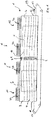
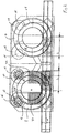
- FIGS 1 and 2 show the inventive oven.
- the oven 1 comprises a first chamber 3 and a second chamber 4.
- the chambers are divided by means of a partition 2.
- a rotatable drum 5, 6 is arranged in each of these chambers, around which the conveyor belt 7 is guided along two helical paths 8, 9.
- the endless conveyor belt enters the oven 1 via the entrance 10 by a straight conveyor belt section 11 and leaves the oven 1 via the exit 12, likewise by means of a straight section 13.
- the two helical sections 8, 9 are connected by the straight conveyor belt section 14, which lies at the top.
- the belt is permeable to the process fluid, e.g. air and steam.
- the partition means 2 comprise a passage 2.1 for the belt section 14. This passage 2.1 is larger than the conveyor belt 14.
- the person skilled in the art understands that the oven needs not necessarily comprise two chambers.
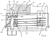
- the heating means which are overall denoted by 15, are arranged in the top of the housing. These heating means 15 each comprise a fan 16 with a spiral casing 17, which opens into a duct 18.
- the heating elements 34 are situated in the ducts 18, respectively.
- the process fluid e.g. air and steam, is sucked up by the fans 16 out of chambers 3, 4 via inlet 24 and is forced into the duct 18 via the spiral casing 17, respectively.
- the process fluid 31 flows past the heating elements 34 and is then recycled into the respective chamber 3, 4.
- Arrow 23, according to figure 3 depicts the fluid flow in the chamber 3, 4.
- the motion of the products (not depicted) to be cooked in the oven is depicted by arrows 29.
- Figure 3 shows a first embodiment of the adjustment means, which is, in the present example a plate 19.
- This plate 19 is located in the straight part 14 of the conveyor belt 7 and extends over the length L, as can be seen in figure 2 .
- the plate 19 is partially located in the duct 18 and extends into a control area 21.
- the plate 19 pivots around an axis 26. The degree of deflection relative to its vertical position is depicted by double-arrow a.
- the plate 19 guides and splits the fluid flow 31 after it has passed the heating means, so that the desired flow pattern over the width of the conveyor belt is achieved.
- the flow 31 can be split and guided from the outside 7" of belt 7 to the inside 7' and vice versa.
- Every desired fluid-flow distribution over the width W can be achieved by means of plate 19. Examples for fluid-flow distributions are shown in Figure 7 .
- the desired fluid-flow distribution is achieved over the entire length L of plate 19.
- Equalization means 20, here a perforated plate are located at the bottom of the control area 21 to support the flow-distribution of plate 19 and/or increase the pressure in the control area.
- the flow 23 inside chamber 3 flows past the helical path 8 and is then sucked up again by fan 16 via inlet 24.
- Plate 19 is motor driven (not depicted). The motor itself is connected to a PLC-controller or adjusted by an operator.
- the position of the plate can be maintained in the same position throughout the entire process or altered in case the cooked products are not as desired and/or the recipe or the incoming product changes.
- the PLC-controller can be additionally connected to a measurement device which measures certain parameters. Based on these measurements, the position of the plate 19 is adjusted automatically.
- Figure 2 also shows the position and extension of the adjustment means in the chamber 4.
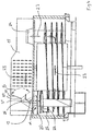
- Figure 4 shows another embodiment of the inventive oven, whereas the adjustment means comprise two plates 19, 28.
- Plate 19 is pivotable as described according to figure 3 .
- Plate 28, which is similarly built and operated as plate 19, is pivotable around axis 27.
- the degree of its defection relative to the horizontal is depicted by arrow ⁇ .
- the two plates allow an even improved control of the flow-rate-distribution over the belt width W.
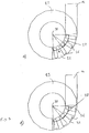
- Figures 5 and 6 show yet another embodiment of the adjustment means. It comprises two plates 31, 30, each having a multitude of parallel, equidistant slots.
- the slots in plate 31 are larger than the slots in plate 30 and are slightly tilted.
- the plates 31, 30 extend over the entire width W of the belt 7 and have a length L. The number of slots needed is dependant from the length L over which the flow rate distribution shall be controlled.
- plate 31 is placed on top of plate 30 and is, as depicted by arrow 33, shiftable relative to plate 30 and preferably parallel to the motion 32 of the belt 7. Arrow 32 depicts the direction of motion of belt 7.
- the slots in the two plates define a passage 34 for the fluid flow.
- Figure 6a shows the two plates 30, 31 in a neutral position.
- the seize of the passage 34 is essentially uniform over the width W of the belt 7.
- Figure 6b depicts a position of the plates, in which the fluid flow is directed to the outside 7" of belt 7', while Figure 6c shows a position of the plates 30,31, which directs the flow to the inside 7'.
- the plate 31 can be actuated automatically, for example by a motor, which is connected to PLC-controller. Based on a set value or on measured parameters, the position of plate 31 is set.
- Figure 7 shows three examples of flow rate distributions, i.e. flow pattern, over the belt width.
- the length of the arrows is proportional to the local velocity, respectively.
- Figure 7a shows a uniform flow rate over the belt width.
- the velocity is higher at the outside 7" of belt 7 than at the inside 7' and in Figure 7c the other way round.
- the integral of the local velocities over the width W is in all cases the same.
- the person skilled in the art understands, however, that due to a better distribution of the flow rate over the belt width, for example a uniform distribution, the overall flow rate can be increased and thus the cooking can be improved without damaging the resulting products.
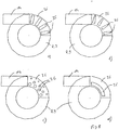
- Figure 8 shows four embodiments of a plate 35 above the helical section 8, 9.
- the plate 35 extends over an angle of 90° and is locate right upstream and/or right downstream of the straight connecting section between the helical sections 8, 9.
- the plate comprises a multitude of rectangular holes, which are oriented essentially perpendicular to the motion of the conveyor belt 7.
- the holes are not rectangular, but decrease in width from the inside to the outside.
- the embodiment according to figure 8c shows a multitude of holes, whereas the number and/or the size of the holes at the inside of the plate is larger than at the outside.
- FIG 9 the embodiments according to figure 8a is shown with two deflector plates 37, which can be rotated around pivot 38 in order to direct more or less fluid-flow to the inside or the outside.
- movement of the deflector plate can also be a pure translational movement or any combination of a translational and a rotational movement.
- Figure 9b shows the embodiment according to figure 9a , whereas in this case, the holes 36 have a different shape, i.e. their width increase from the inside to the outside.
Landscapes
- Life Sciences & Earth Sciences (AREA)
- Engineering & Computer Science (AREA)
- Food Science & Technology (AREA)
- Commercial Cooking Devices (AREA)
- Baking, Grill, Roasting (AREA)
- Furnace Details (AREA)
- Tunnel Furnaces (AREA)
- General Preparation And Processing Of Foods (AREA)
- Meat, Egg Or Seafood Products (AREA)
Claims (8)
- Four (1) comportant :- une première chambre [3, 4)- des moyens (7) de convoyeur présentant une largeur (W) servant à guider des produits à partir de l'entrée (10) à travers cette chambre (3, 4) jusqu'à la sortie (12), les moyens de convoyeur étant au moins partiellement agencés en un trajet hélicoïdal (8),- des moyens (15) de régulation de température servant à réguler la température et/ou l'humidité dans la chambre à l'aide d'un fluide (23), qui comportent un réchauffeur (34) servant à chauffer le fluide et une gaine (18) servant à introduire le fluide chauffé dans la chambre (3, 4),
celui-ci comportant des moyens (19, 28, 31) servant à régler la répartition de débit sur la largeur (W) des moyens (7) de convoyeur en fonction d'au moins un paramètre de processus et/ou d'une recette,
les moyens (19, 28, 31) étant une plaque (35) présentant un ou plusieurs trous (36) et une plaque (37) de déflecteur, qui règlent le débit sur toute la largeur (W) des moyens (7) de convoyeur et qui sont commandés par des moyens informatiques, en fonction d'au moins un paramètre de processus et/ou d'une recette,
caractérisé en ce qu'il comporte des moyens (35, 36, 37) de réglage de débit de fluide dans la zone du trajet hélicoïdal (8, 9), de préférence au-dessus du trajet hélicoïdal,
la répartition du débit étant réglée sur toute la largeur des moyens de convoyeur, c.à.d. que le débit est augmenté dans une partie de la largeur de la bande et simultanément diminué dans une autre partie de la largeur de la bande, tandis que l'intégrale sur la largeur de la bande reste essentiellement inchangée. - Four (1) selon la revendication 1, caractérisé en ce qu'il comporte un dispositif de mesure et en ce que les moyens (19, 28, 31) sont de préférence réglés selon le signal de ce dispositif.
- Four (1) selon l'une des revendications précédentes, caractérisé en ce que les moyens (19, 28, 31) sont situés dans la zone où le fluide chauffé (23) est introduit dans la chambre (3, 4).
- Four (1) selon l'une des revendications précédentes, caractérisé en ce qu'il comporte une seconde chambre (4) dotée d'un second trajet hélicoïdal (9) et en ce que les deux trajets hélicoïdaux (8, 9) sont de préférence reliés par une section (14) de moyens de convoyeur rectiligne.
- Four (1) selon la revendication 4, caractérisé en ce que les moyens (19, 28, 31) sont situés dans la section (14) .
- Four (1) selon l'une des revendications précédentes, caractérisé en ce qu'il comporte des moyens (20) servant à égaliser le débit (31).
- Four selon l'une des revendications précédentes, caractérisé en ce qu'il comporte des moyens servant à faire fluctuer le débit volumique du fluide chauffé, sa température, son humidité et/ou sa vitesse et de préférence à le diriger à travers une plaque vers les moyens (7) de convoyeur.
- Four selon l'une des revendications précédentes, le débit (23) étant augmenté dans une partie de la bande (7) et simultanément diminué dans une autre partie de la bande (7).
Priority Applications (3)
| Application Number | Priority Date | Filing Date | Title |
|---|---|---|---|
| ES15182324T ES2879632T3 (es) | 2008-06-19 | 2008-06-19 | Horno en espiral con flujo de aire controlado a lo largo de la anchura de la cinta |
| PL15182324T PL2987410T3 (pl) | 2008-06-19 | 2008-06-19 | Piec spiralny z kontrolowanym przepływem powietrza na szerokości taśmy |
| EP15182324.2A EP2987410B1 (fr) | 2008-06-19 | 2008-06-19 | Four à spirale avec flux d'air contrôlé sur la largeur de la courroie |
Applications Claiming Priority (2)
| Application Number | Priority Date | Filing Date | Title |
|---|---|---|---|
| EP08011161.0A EP2135509B1 (fr) | 2008-06-19 | 2008-06-19 | Four avec une contrôle du débit d'air sur la largeur d'une courroie dans un four à spirale |
| EP15182324.2A EP2987410B1 (fr) | 2008-06-19 | 2008-06-19 | Four à spirale avec flux d'air contrôlé sur la largeur de la courroie |
Related Parent Applications (1)
| Application Number | Title | Priority Date | Filing Date |
|---|---|---|---|
| EP08011161.0A Division EP2135509B1 (fr) | 2008-06-19 | 2008-06-19 | Four avec une contrôle du débit d'air sur la largeur d'une courroie dans un four à spirale |
Publications (2)
| Publication Number | Publication Date |
|---|---|
| EP2987410A1 EP2987410A1 (fr) | 2016-02-24 |
| EP2987410B1 true EP2987410B1 (fr) | 2021-04-28 |
Family
ID=39769265
Family Applications (2)
| Application Number | Title | Priority Date | Filing Date |
|---|---|---|---|
| EP08011161.0A Active EP2135509B1 (fr) | 2008-06-19 | 2008-06-19 | Four avec une contrôle du débit d'air sur la largeur d'une courroie dans un four à spirale |
| EP15182324.2A Active EP2987410B1 (fr) | 2008-06-19 | 2008-06-19 | Four à spirale avec flux d'air contrôlé sur la largeur de la courroie |
Family Applications Before (1)
| Application Number | Title | Priority Date | Filing Date |
|---|---|---|---|
| EP08011161.0A Active EP2135509B1 (fr) | 2008-06-19 | 2008-06-19 | Four avec une contrôle du débit d'air sur la largeur d'une courroie dans un four à spirale |
Country Status (8)
| Country | Link |
|---|---|
| US (1) | US8415592B2 (fr) |
| EP (2) | EP2135509B1 (fr) |
| CN (1) | CN102123597B (fr) |
| BR (1) | BRPI0915808A2 (fr) |
| CA (1) | CA2728475C (fr) |
| ES (2) | ES2557479T3 (fr) |
| PL (2) | PL2987410T3 (fr) |
| WO (1) | WO2009153062A1 (fr) |
Families Citing this family (12)
| Publication number | Priority date | Publication date | Assignee | Title |
|---|---|---|---|---|
| US8646383B1 (en) * | 2009-09-15 | 2014-02-11 | David Howard | Spiral oven apparatus and method of cooking |
| EP2806744A1 (fr) * | 2012-01-27 | 2014-12-03 | TS Techniek BV | Four en spirale à deux tambours |
| US9538880B2 (en) * | 2012-05-09 | 2017-01-10 | Convotherm Elektrogeraete Gmbh | Optical quality control system |
| KR102037371B1 (ko) * | 2013-02-27 | 2019-10-28 | 엘지전자 주식회사 | 조리기기 및 이의 제어방법 |
| CN103141533A (zh) * | 2013-04-11 | 2013-06-12 | 朱小龙 | 火柴盒式烤箱 |
| US10039304B2 (en) | 2015-05-06 | 2018-08-07 | John Bean Technologies Ab | System and method for adjusting air flow in spiral conveyers |
| WO2017147473A1 (fr) | 2016-02-26 | 2017-08-31 | Provisur Technologies, Inc. | Dispositifs de cuisson et leurs procédés d'utilisation |
| WO2017192955A1 (fr) | 2016-05-05 | 2017-11-09 | Provisur Technologies, Inc. | Dispositifs de cuisson en spirale et leurs procédés d'utilisation |
| KR101798788B1 (ko) * | 2016-10-20 | 2017-11-16 | 장동현 | 음식물 이송 건조장치 |
| KR101957825B1 (ko) * | 2017-01-31 | 2019-07-04 | 주식회사 협진기계 | 스파이럴 오븐기용 열기 순환장치 |
| US11134712B2 (en) | 2018-08-08 | 2021-10-05 | Mp Equipment Llc | Adjustable breading machine and method of operation |
| US10912317B2 (en) | 2018-10-19 | 2021-02-09 | John Bean Technologies Ab | Thermal processing apparatus |
Citations (6)
| Publication number | Priority date | Publication date | Assignee | Title |
|---|---|---|---|---|
| DE1267605B (de) * | 1963-03-11 | 1968-05-02 | Foerdertechnik G M B H | Gliederband als Wendelbahnfoerderer einer Behandlungsanlage, z. B. zum Kuehlen, Trocknen, Backen oder Sterilisieren von Gut |
| EP0558151A1 (fr) | 1992-02-26 | 1993-09-01 | Tetra Laval Food Koppens B.V. | Four |
| GB2311268A (en) | 1996-03-20 | 1997-09-24 | Stein Inc | Conveyor for processing equipment having gas flow compensation |
| EP0804878A1 (fr) * | 1996-05-03 | 1997-11-05 | Koppens B.V. | Four à guidage d'air de chauffage |
| EP1221575A1 (fr) | 2001-01-05 | 2002-07-10 | Koppens B.V. | Four avec système à jet de fluide |
| US20070137633A1 (en) | 2004-03-05 | 2007-06-21 | Mcfadden David | Conveyor oven |
Family Cites Families (44)
| Publication number | Priority date | Publication date | Assignee | Title |
|---|---|---|---|---|
| US2161211A (en) * | 1937-10-18 | 1939-06-06 | Werner Frank Charles | Baking oven |
| US2767668A (en) * | 1950-08-22 | 1956-10-23 | Spooner Food Machinery Enginee | Baking of food products |
| US2784685A (en) * | 1952-07-15 | 1957-03-12 | T & T Vicars Ltd | Bakers' ovens and the like heating chambers |
| GB803740A (en) * | 1955-12-05 | 1958-10-29 | Baker Perkins Ltd | Improvements in and relating to bakers' and like ovens |
| GB903110A (en) * | 1960-02-12 | 1962-08-09 | Baker Perkins Ltd | Air agitation system for baking ovens |
| US3789516A (en) * | 1971-10-08 | 1974-02-05 | Werner & Pfleiderer | Continuous tunnel oven for baking and/or drying |
| US3908533A (en) * | 1973-04-04 | 1975-09-30 | Electrolux Ab | Apparatus for continuously cooking food in sequential oven section of an elongated oven |
| US4348948A (en) * | 1980-01-28 | 1982-09-14 | Hager And Allison Corp. | Cooking apparatus |
| US4344973A (en) * | 1980-11-04 | 1982-08-17 | Blake Anthony A | Method for curing and smoking pork skins to condition them for rendering |
| US4631029A (en) * | 1983-12-09 | 1986-12-23 | Lanham Machinery Company, Inc. | Baking oven with heated air distribution-II |
| WO1985005546A1 (fr) | 1984-05-31 | 1985-12-19 | Robert Bruce Forney | Four a alimentation continue |
| US4563945A (en) * | 1984-11-13 | 1986-01-14 | Stein Associates, Inc. | Heat shield-steam distributor for cooking oven |
| US4726766A (en) * | 1986-12-01 | 1988-02-23 | Stewart Systems, Inc. | Air circulation and exhaust control system for commerical ovens |
| US4737373A (en) * | 1987-02-11 | 1988-04-12 | Forney Robert B | Cooking and browning system |
| US4834063A (en) | 1987-05-28 | 1989-05-30 | Stein Associates, Inc. | Food cooking oven with duct fingers and method |
| US6041398A (en) * | 1992-06-26 | 2000-03-21 | International Business Machines Corporation | Massively parallel multiple-folded clustered processor mesh array |
| US5078120A (en) | 1990-01-26 | 1992-01-07 | Stein, Inc. | Cooking oven for slow cooking of food products |
| US5243962A (en) * | 1990-01-26 | 1993-09-14 | Stein, Inc. | Cooking oven for slow-cooking of food products |
| US5189948A (en) * | 1991-02-05 | 1993-03-02 | Beltec International | Low temperature spiral conduction vapor cooker and process |
| US5322007A (en) | 1991-08-15 | 1994-06-21 | Heat And Control, Inc. | Compact, high-capacity oven |
| CN2190408Y (zh) * | 1994-04-21 | 1995-03-01 | 牛振裕 | 一种花生烤炉 |
| DK172989B1 (da) * | 1995-05-19 | 1999-11-01 | Scanio As | Massereanlæg |
| US5564332A (en) * | 1995-12-05 | 1996-10-15 | Wti, Inc. | Meat massaging machine |
| NL1004285C2 (nl) * | 1996-10-15 | 1998-04-20 | Koppens Bv | Oven met boven elkaar liggende zones. |
| EP0859199B1 (fr) * | 1997-01-04 | 2004-10-20 | Heat and Control, Inc. | Four à air circulé |
| NL1005803C2 (nl) * | 1997-04-11 | 1998-10-14 | Koppens Convenience Food Syste | Stoomoven. |
| CN2302658Y (zh) * | 1997-08-20 | 1999-01-06 | 杨延光 | 螺旋式食品烘烤炉 |
| NL1011199C1 (nl) | 1998-04-28 | 1999-10-29 | Stork Titan Bv | Behandelingsinrichting voor het met geconditioneerde lucht behandelen van voedselproducten. |
| CN2333191Y (zh) * | 1998-06-19 | 1999-08-18 | 烟台枫林食品有限公司 | 隧道式热风烘烤炉 |
| US5881636A (en) * | 1998-07-01 | 1999-03-16 | Sweet; Dan | Heat impingement bake oven |
| US6105490A (en) * | 1998-08-03 | 2000-08-22 | Horn; Darrell | Apparatus for marinating meat products |
| WO2000013528A1 (fr) | 1998-09-04 | 2000-03-16 | Rhm Technology Limited | Four a jet d'air |
| US6065463A (en) * | 1998-10-19 | 2000-05-23 | Sasib Bakery North America, Inc. | Forced convective track oven |
| US6138660A (en) * | 1999-01-06 | 2000-10-31 | Sasib Bakery North America, Inc. | Forced convective track oven having oval spirals |
| JP2002539418A (ja) * | 1999-03-23 | 2002-11-19 | ピッツァ・ハット・インコーポレイテッド | 衝突式オーブン空気流装置及び方法 |
| US6049066A (en) * | 1999-03-26 | 2000-04-11 | Wilson; W. Robert | Concentric air delivery and return oven |
| NL1012244C2 (nl) * | 1999-06-04 | 2000-12-06 | Koppens Bv | Spiraaloven met verbeterde bandaandrijving. |
| NL1013768C2 (nl) * | 1999-12-06 | 2001-06-07 | Koppens Bv | Transportbandsysteem, alsmede braadoven. |
| US20020006457A1 (en) * | 2000-03-15 | 2002-01-17 | Wolfgang Ludwig | Method of and apparatus for the processing of meat |
| NL1017755C2 (nl) * | 2001-04-02 | 2002-10-03 | Cfs Bakel Bv | Oven met druppelopvang. |
| NL1026302C2 (nl) * | 2004-06-01 | 2005-12-05 | Stork Titan Bv | Thermokoppel en toepassing daarvan. |
| GB0518186D0 (en) | 2005-09-07 | 2005-10-12 | Fylde Thermal Engineering Ltd | Tunnel oven |
| EP2043771A2 (fr) * | 2006-07-07 | 2009-04-08 | CFS Bakel B.V. | Batteur |
| CN101006834A (zh) * | 2007-01-18 | 2007-08-01 | 陈碧雅 | 螺旋式食品加热设备 |
-
2008
- 2008-06-19 ES ES08011161.0T patent/ES2557479T3/es active Active
- 2008-06-19 EP EP08011161.0A patent/EP2135509B1/fr active Active
- 2008-06-19 EP EP15182324.2A patent/EP2987410B1/fr active Active
- 2008-06-19 ES ES15182324T patent/ES2879632T3/es active Active
- 2008-06-19 PL PL15182324T patent/PL2987410T3/pl unknown
- 2008-06-19 PL PL08011161T patent/PL2135509T3/pl unknown
-
2009
- 2009-06-19 BR BRPI0915808A patent/BRPI0915808A2/pt not_active Application Discontinuation
- 2009-06-19 CN CN2009801315044A patent/CN102123597B/zh not_active Expired - Fee Related
- 2009-06-19 WO PCT/EP2009/004462 patent/WO2009153062A1/fr active Application Filing
- 2009-06-19 CA CA2728475A patent/CA2728475C/fr not_active Expired - Fee Related
- 2009-06-19 US US12/999,699 patent/US8415592B2/en not_active Expired - Fee Related
Patent Citations (6)
| Publication number | Priority date | Publication date | Assignee | Title |
|---|---|---|---|---|
| DE1267605B (de) * | 1963-03-11 | 1968-05-02 | Foerdertechnik G M B H | Gliederband als Wendelbahnfoerderer einer Behandlungsanlage, z. B. zum Kuehlen, Trocknen, Backen oder Sterilisieren von Gut |
| EP0558151A1 (fr) | 1992-02-26 | 1993-09-01 | Tetra Laval Food Koppens B.V. | Four |
| GB2311268A (en) | 1996-03-20 | 1997-09-24 | Stein Inc | Conveyor for processing equipment having gas flow compensation |
| EP0804878A1 (fr) * | 1996-05-03 | 1997-11-05 | Koppens B.V. | Four à guidage d'air de chauffage |
| EP1221575A1 (fr) | 2001-01-05 | 2002-07-10 | Koppens B.V. | Four avec système à jet de fluide |
| US20070137633A1 (en) | 2004-03-05 | 2007-06-21 | Mcfadden David | Conveyor oven |
Also Published As
| Publication number | Publication date |
|---|---|
| EP2135509A1 (fr) | 2009-12-23 |
| ES2879632T3 (es) | 2021-11-22 |
| BRPI0915808A2 (pt) | 2015-11-10 |
| WO2009153062A1 (fr) | 2009-12-23 |
| CN102123597B (zh) | 2013-11-06 |
| CA2728475A1 (fr) | 2009-12-23 |
| ES2557479T3 (es) | 2016-01-26 |
| CN102123597A (zh) | 2011-07-13 |
| CA2728475C (fr) | 2017-02-14 |
| EP2987410A1 (fr) | 2016-02-24 |
| PL2987410T3 (pl) | 2021-11-08 |
| EP2135509B1 (fr) | 2015-09-23 |
| US20110168689A1 (en) | 2011-07-14 |
| PL2135509T3 (pl) | 2016-03-31 |
| US8415592B2 (en) | 2013-04-09 |
Similar Documents
| Publication | Publication Date | Title |
|---|---|---|
| EP2987410B1 (fr) | Four à spirale avec flux d'air contrôlé sur la largeur de la courroie | |
| NL2001142C2 (nl) | Behandelingsinrichting, in het bijzonder oven. | |
| EP2139341B1 (fr) | Four à convoyeur compact | |
| EP3335564B1 (fr) | Processus de contrôle du dèbit d'air et des fuites d'air entre deux chambres de cuisson | |
| DE102007039379B4 (de) | Gargerät mit mehreren Klimazonen | |
| US9700059B2 (en) | Treatment device and method for treating food products with conditioned air | |
| TW201829972A (zh) | 產品乾燥設備及方法 | |
| EP3365606B1 (fr) | Four à convection | |
| EP3376872B1 (fr) | Four à traînée améliorée | |
| EP4136387A1 (fr) | Dispositif de cuisson | |
| EP3641549B1 (fr) | Four à alimentation en fumée et procédé de fonctionnement d'un tel four | |
| WO2023213376A1 (fr) | Dispositif de cuisson ayant deux zones dans la cavité de cuisson |
Legal Events
| Date | Code | Title | Description |
|---|---|---|---|
| PUAI | Public reference made under article 153(3) epc to a published international application that has entered the european phase |
Free format text: ORIGINAL CODE: 0009012 |
|
| AC | Divisional application: reference to earlier application |
Ref document number: 2135509 Country of ref document: EP Kind code of ref document: P |
|
| AK | Designated contracting states |
Kind code of ref document: A1 Designated state(s): AT BE BG CH CY CZ DE DK EE ES FI FR GB GR HR HU IE IS IT LI LT LU LV MC MT NL NO PL PT RO SE SI SK TR |
|
| 17P | Request for examination filed |
Effective date: 20160818 |
|
| RBV | Designated contracting states (corrected) |
Designated state(s): AT BE BG CH CY CZ DE DK EE ES FI FR GB GR HR HU IE IS IT LI LT LU LV MC MT NL NO PL PT RO SE SI SK TR |
|
| STAA | Information on the status of an ep patent application or granted ep patent |
Free format text: STATUS: EXAMINATION IS IN PROGRESS |
|
| 17Q | First examination report despatched |
Effective date: 20180802 |
|
| GRAP | Despatch of communication of intention to grant a patent |
Free format text: ORIGINAL CODE: EPIDOSNIGR1 |
|
| STAA | Information on the status of an ep patent application or granted ep patent |
Free format text: STATUS: GRANT OF PATENT IS INTENDED |
|
| INTG | Intention to grant announced |
Effective date: 20201111 |
|
| GRAS | Grant fee paid |
Free format text: ORIGINAL CODE: EPIDOSNIGR3 |
|
| GRAA | (expected) grant |
Free format text: ORIGINAL CODE: 0009210 |
|
| STAA | Information on the status of an ep patent application or granted ep patent |
Free format text: STATUS: THE PATENT HAS BEEN GRANTED |
|
| AC | Divisional application: reference to earlier application |
Ref document number: 2135509 Country of ref document: EP Kind code of ref document: P |
|
| AK | Designated contracting states |
Kind code of ref document: B1 Designated state(s): AT BE BG CH CY CZ DE DK EE ES FI FR GB GR HR HU IE IS IT LI LT LU LV MC MT NL NO PL PT RO SE SI SK TR |
|
| REG | Reference to a national code |
Ref country code: GB Ref legal event code: FG4D |
|
| REG | Reference to a national code |
Ref country code: CH Ref legal event code: EP |
|
| REG | Reference to a national code |
Ref country code: AT Ref legal event code: REF Ref document number: 1386075 Country of ref document: AT Kind code of ref document: T Effective date: 20210515 |
|
| REG | Reference to a national code |
Ref country code: DE Ref legal event code: R096 Ref document number: 602008063921 Country of ref document: DE |
|
| REG | Reference to a national code |
Ref country code: IE Ref legal event code: FG4D |
|
| REG | Reference to a national code |
Ref country code: NL Ref legal event code: FP |
|
| REG | Reference to a national code |
Ref country code: SE Ref legal event code: TRGR |
|
| REG | Reference to a national code |
Ref country code: LT Ref legal event code: MG9D |
|
| PGFP | Annual fee paid to national office [announced via postgrant information from national office to epo] |
Ref country code: SE Payment date: 20210616 Year of fee payment: 14 |
|
| REG | Reference to a national code |
Ref country code: SK Ref legal event code: T3 Ref document number: E 37705 Country of ref document: SK |
|
| REG | Reference to a national code |
Ref country code: AT Ref legal event code: MK05 Ref document number: 1386075 Country of ref document: AT Kind code of ref document: T Effective date: 20210428 |
|
| PG25 | Lapsed in a contracting state [announced via postgrant information from national office to epo] |
Ref country code: FI Free format text: LAPSE BECAUSE OF FAILURE TO SUBMIT A TRANSLATION OF THE DESCRIPTION OR TO PAY THE FEE WITHIN THE PRESCRIBED TIME-LIMIT Effective date: 20210428 Ref country code: LT Free format text: LAPSE BECAUSE OF FAILURE TO SUBMIT A TRANSLATION OF THE DESCRIPTION OR TO PAY THE FEE WITHIN THE PRESCRIBED TIME-LIMIT Effective date: 20210428 Ref country code: BG Free format text: LAPSE BECAUSE OF FAILURE TO SUBMIT A TRANSLATION OF THE DESCRIPTION OR TO PAY THE FEE WITHIN THE PRESCRIBED TIME-LIMIT Effective date: 20210728 Ref country code: AT Free format text: LAPSE BECAUSE OF FAILURE TO SUBMIT A TRANSLATION OF THE DESCRIPTION OR TO PAY THE FEE WITHIN THE PRESCRIBED TIME-LIMIT Effective date: 20210428 Ref country code: HR Free format text: LAPSE BECAUSE OF FAILURE TO SUBMIT A TRANSLATION OF THE DESCRIPTION OR TO PAY THE FEE WITHIN THE PRESCRIBED TIME-LIMIT Effective date: 20210428 |
|
| REG | Reference to a national code |
Ref country code: ES Ref legal event code: FG2A Ref document number: 2879632 Country of ref document: ES Kind code of ref document: T3 Effective date: 20211122 |
|
| PG25 | Lapsed in a contracting state [announced via postgrant information from national office to epo] |
Ref country code: GR Free format text: LAPSE BECAUSE OF FAILURE TO SUBMIT A TRANSLATION OF THE DESCRIPTION OR TO PAY THE FEE WITHIN THE PRESCRIBED TIME-LIMIT Effective date: 20210729 Ref country code: IS Free format text: LAPSE BECAUSE OF FAILURE TO SUBMIT A TRANSLATION OF THE DESCRIPTION OR TO PAY THE FEE WITHIN THE PRESCRIBED TIME-LIMIT Effective date: 20210828 Ref country code: LV Free format text: LAPSE BECAUSE OF FAILURE TO SUBMIT A TRANSLATION OF THE DESCRIPTION OR TO PAY THE FEE WITHIN THE PRESCRIBED TIME-LIMIT Effective date: 20210428 Ref country code: NO Free format text: LAPSE BECAUSE OF FAILURE TO SUBMIT A TRANSLATION OF THE DESCRIPTION OR TO PAY THE FEE WITHIN THE PRESCRIBED TIME-LIMIT Effective date: 20210728 Ref country code: PT Free format text: LAPSE BECAUSE OF FAILURE TO SUBMIT A TRANSLATION OF THE DESCRIPTION OR TO PAY THE FEE WITHIN THE PRESCRIBED TIME-LIMIT Effective date: 20210830 |
|
| REG | Reference to a national code |
Ref country code: DE Ref legal event code: R026 Ref document number: 602008063921 Country of ref document: DE |
|
| PG25 | Lapsed in a contracting state [announced via postgrant information from national office to epo] |
Ref country code: DK Free format text: LAPSE BECAUSE OF FAILURE TO SUBMIT A TRANSLATION OF THE DESCRIPTION OR TO PAY THE FEE WITHIN THE PRESCRIBED TIME-LIMIT Effective date: 20210428 Ref country code: CZ Free format text: LAPSE BECAUSE OF FAILURE TO SUBMIT A TRANSLATION OF THE DESCRIPTION OR TO PAY THE FEE WITHIN THE PRESCRIBED TIME-LIMIT Effective date: 20210428 Ref country code: EE Free format text: LAPSE BECAUSE OF FAILURE TO SUBMIT A TRANSLATION OF THE DESCRIPTION OR TO PAY THE FEE WITHIN THE PRESCRIBED TIME-LIMIT Effective date: 20210428 Ref country code: MC Free format text: LAPSE BECAUSE OF FAILURE TO SUBMIT A TRANSLATION OF THE DESCRIPTION OR TO PAY THE FEE WITHIN THE PRESCRIBED TIME-LIMIT Effective date: 20210428 Ref country code: RO Free format text: LAPSE BECAUSE OF FAILURE TO SUBMIT A TRANSLATION OF THE DESCRIPTION OR TO PAY THE FEE WITHIN THE PRESCRIBED TIME-LIMIT Effective date: 20210428 |
|
| REG | Reference to a national code |
Ref country code: CH Ref legal event code: PL |
|
| PLBI | Opposition filed |
Free format text: ORIGINAL CODE: 0009260 |
|
| PLAX | Notice of opposition and request to file observation + time limit sent |
Free format text: ORIGINAL CODE: EPIDOSNOBS2 |
|
| 26 | Opposition filed |
Opponent name: MAREL FURTHER PROCESSING B.V. Effective date: 20220128 |
|
| REG | Reference to a national code |
Ref country code: BE Ref legal event code: MM Effective date: 20210630 |
|
| PG25 | Lapsed in a contracting state [announced via postgrant information from national office to epo] |
Ref country code: LU Free format text: LAPSE BECAUSE OF NON-PAYMENT OF DUE FEES Effective date: 20210619 |
|
| PG25 | Lapsed in a contracting state [announced via postgrant information from national office to epo] |
Ref country code: LI Free format text: LAPSE BECAUSE OF NON-PAYMENT OF DUE FEES Effective date: 20210630 Ref country code: IE Free format text: LAPSE BECAUSE OF NON-PAYMENT OF DUE FEES Effective date: 20210619 Ref country code: CH Free format text: LAPSE BECAUSE OF NON-PAYMENT OF DUE FEES Effective date: 20210630 |
|
| PG25 | Lapsed in a contracting state [announced via postgrant information from national office to epo] |
Ref country code: IS Free format text: LAPSE BECAUSE OF FAILURE TO SUBMIT A TRANSLATION OF THE DESCRIPTION OR TO PAY THE FEE WITHIN THE PRESCRIBED TIME-LIMIT Effective date: 20210828 |
|
| PLBB | Reply of patent proprietor to notice(s) of opposition received |
Free format text: ORIGINAL CODE: EPIDOSNOBS3 |
|
| PG25 | Lapsed in a contracting state [announced via postgrant information from national office to epo] |
Ref country code: BE Free format text: LAPSE BECAUSE OF NON-PAYMENT OF DUE FEES Effective date: 20210630 |
|
| REG | Reference to a national code |
Ref country code: SE Ref legal event code: EUG |
|
| PG25 | Lapsed in a contracting state [announced via postgrant information from national office to epo] |
Ref country code: SE Free format text: LAPSE BECAUSE OF NON-PAYMENT OF DUE FEES Effective date: 20220620 |
|
| PG25 | Lapsed in a contracting state [announced via postgrant information from national office to epo] |
Ref country code: HU Free format text: LAPSE BECAUSE OF FAILURE TO SUBMIT A TRANSLATION OF THE DESCRIPTION OR TO PAY THE FEE WITHIN THE PRESCRIBED TIME-LIMIT; INVALID AB INITIO Effective date: 20080619 Ref country code: CY Free format text: LAPSE BECAUSE OF FAILURE TO SUBMIT A TRANSLATION OF THE DESCRIPTION OR TO PAY THE FEE WITHIN THE PRESCRIBED TIME-LIMIT Effective date: 20210428 |
|
| P01 | Opt-out of the competence of the unified patent court (upc) registered |
Effective date: 20230519 |
|
| PGFP | Annual fee paid to national office [announced via postgrant information from national office to epo] |
Ref country code: NL Payment date: 20230620 Year of fee payment: 16 Ref country code: FR Payment date: 20230619 Year of fee payment: 16 Ref country code: DE Payment date: 20230620 Year of fee payment: 16 |
|
| PGFP | Annual fee paid to national office [announced via postgrant information from national office to epo] |
Ref country code: SK Payment date: 20230616 Year of fee payment: 16 Ref country code: PL Payment date: 20230612 Year of fee payment: 16 |
|
| REG | Reference to a national code |
Ref country code: DE Ref legal event code: R100 Ref document number: 602008063921 Country of ref document: DE |
|
| PGFP | Annual fee paid to national office [announced via postgrant information from national office to epo] |
Ref country code: IT Payment date: 20230630 Year of fee payment: 16 Ref country code: GB Payment date: 20230622 Year of fee payment: 16 Ref country code: ES Payment date: 20230719 Year of fee payment: 16 |
|
| PLCK | Communication despatched that opposition was rejected |
Free format text: ORIGINAL CODE: EPIDOSNREJ1 |
|
| PLBN | Opposition rejected |
Free format text: ORIGINAL CODE: 0009273 |
|
| STAA | Information on the status of an ep patent application or granted ep patent |
Free format text: STATUS: OPPOSITION REJECTED |
|
| 27O | Opposition rejected |
Effective date: 20231024 |