EP2987236B1 - Procédé d'alimentation électrique d'un moteur électrique, programme d'ordinateur associé, dispositif de commande d'un onduleur et machine tournante électrique - Google Patents
Procédé d'alimentation électrique d'un moteur électrique, programme d'ordinateur associé, dispositif de commande d'un onduleur et machine tournante électrique Download PDFInfo
- Publication number
- EP2987236B1 EP2987236B1 EP14727580.4A EP14727580A EP2987236B1 EP 2987236 B1 EP2987236 B1 EP 2987236B1 EP 14727580 A EP14727580 A EP 14727580A EP 2987236 B1 EP2987236 B1 EP 2987236B1
- Authority
- EP
- European Patent Office
- Prior art keywords
- phase
- phases
- current vector
- revolution
- current
- Prior art date
- Legal status (The legal status is an assumption and is not a legal conclusion. Google has not performed a legal analysis and makes no representation as to the accuracy of the status listed.)
- Active
Links
Images


Classifications
-
- H—ELECTRICITY
- H02—GENERATION; CONVERSION OR DISTRIBUTION OF ELECTRIC POWER
- H02P—CONTROL OR REGULATION OF ELECTRIC MOTORS, ELECTRIC GENERATORS OR DYNAMO-ELECTRIC CONVERTERS; CONTROLLING TRANSFORMERS, REACTORS OR CHOKE COILS
- H02P6/00—Arrangements for controlling synchronous motors or other dynamo-electric motors using electronic commutation dependent on the rotor position; Electronic commutators therefor
- H02P6/14—Electronic commutators
-
- H—ELECTRICITY
- H02—GENERATION; CONVERSION OR DISTRIBUTION OF ELECTRIC POWER
- H02P—CONTROL OR REGULATION OF ELECTRIC MOTORS, ELECTRIC GENERATORS OR DYNAMO-ELECTRIC CONVERTERS; CONTROLLING TRANSFORMERS, REACTORS OR CHOKE COILS
- H02P27/00—Arrangements or methods for the control of AC motors characterised by the kind of supply voltage
- H02P27/04—Arrangements or methods for the control of AC motors characterised by the kind of supply voltage using variable-frequency supply voltage, e.g. inverter or converter supply voltage
- H02P27/06—Arrangements or methods for the control of AC motors characterised by the kind of supply voltage using variable-frequency supply voltage, e.g. inverter or converter supply voltage using DC to AC converters or inverters
Definitions
- the present invention relates to a method for supplying electricity to an electric motor, an associated computer program, a device for controlling an inverter and an electric rotating machine.
- the French patent application published under number FR 2 974 466 describes a method of supplying electricity to an electric motor comprising phases having respective directions around an axis of rotation of the electric motor and intended to be respectively traversed by phase currents defining a current vector starting from the axis of rotation, the method comprising the switched connection of the phases to a voltage source so as to rotate the current vector.
- a control device is generally intended to control an inverter so that the latter performs switching operations alternately applying voltages to each phase, for example the voltage supplied by the direct voltage source and its opposite.
- disconnection steps on one part of the turn and connection steps for the other part of the turn are applied to all phases of the electric motor.
- the part of the turn on which the phase is disconnected from the voltage source comprises two separate sub-parts through each of which passes the perpendicular to the direction of the disconnectable phase.
- only one phase is disconnected, to be open-circuited, at a time.
- Also provided is a computer program comprising lines of code which, when executed by a computer, causes the computer to control an inverter connecting an electric motor to a voltage source, so as to implement a method according to the invention.
- FIG. 1 Electric rotating machine 100
- an electric rotating machine 100 according to the invention will now be described.
- the rotating machine 100 is used to drive a rotating rotor from a voltage source (operation of engine), but the invention extends to electric generators, the rotating machine is then intended to supply electricity to the voltage source from the rotation of the rotor.
- the electric rotating machine 100 firstly comprises a voltage source 102 intended to provide a direct voltage E relative to an electrical ground M.
- the electric rotating machine 100 further comprises an electric motor 104.
- the electric motor 104 comprises a stator and a rotor intended to rotate relative to the stator about an axis of rotation A.
- the electric motor 104 further comprises three phases u, v, w having directions distributed equally in a plane transverse to the axis of rotation A, and thus separated from each other by 120° in this transverse plane.
- Each phase u, v, w has two terminals.
- the phases u, v, w are independent, that is to say that they are not connected together by one of their terminals.
- the phases u, v, w are intended to be respectively traversed by phase currents i u , i v , i w .
- phase currents i u , i v , i w define a current vector i belonging to the plane transverse to the axis of rotation A and perpendicular to the axis of rotation A. More precisely, each phase current i u , i v , i w defines a phase vector having, on the one hand, as direction, the direction of the phase u, v, w that it travels and, on the other hand, as norm, the value of this phase current i u , i v , i w .
- the current vector i is then defined as the vector sum of the phase vectors. This current vector 1 follows the rotation of the rotor, and therefore makes it possible to represent the position of the rotor.
- the rotary drive system 100 further comprises an inverter 106 intended to connect in a switched manner each phase u, v, w of the electric motor 104 to the DC voltage source 102.
- the inverter 106 is intended to connect or disconnect in a switched manner each terminal of the phases u, v, w to the voltage E or to the ground M, so as to selectively apply to each phase u, v, w the voltage +E, its opposite -E, a zero voltage, or else disconnect the two terminals to put the phase u, v, w in open circuit and thus cut off the current in the phase u, v, w.
- the inverter comprises in particular switches each connecting a terminal of the voltage source 102 to a terminal of a phase u, v, w.
- an H-bridge is produced for each phase u, v, w.
- the inverter 106 therefore comprises three H-bridges and twelve switches.
- the inverter 106 comprises a freewheeling diode in parallel with each switch.
- the rotary drive system 100 further comprises a sensor 108 intended to measure the phase currents i u , i v , i w .
- the rotary drive system 100 further comprises a control device 110 intended to control the inverter 106 so that the latter makes a switched connection of the phases u, v, w to the voltage source 102 so as to rotate the current vector i around the axis of rotation A, causing the rotor to rotate relative to the stator.
- a control device 110 intended to control the inverter 106 so that the latter makes a switched connection of the phases u, v, w to the voltage source 102 so as to rotate the current vector i around the axis of rotation A, causing the rotor to rotate relative to the stator.
- control device 110 is a computer (sometimes called a "calculator") comprising a memory 112 in which a computer program is recorded and a processing unit 114 intended to execute the computer program.
- the latter comprises instructions which, when executed by the control device 110, that is to say by the processing unit 114, cause the control by the control device 110 of the inverter 106 so as to implement steps of the method of electrically supplying the electric motor 104 which will be described later, with reference to the figure 3 .
- at least one association between at least one predetermined angular sector and a predetermined phase is stored in the memory 112.
- each angular sector is represented in the memory 112 by the angle range it covers.
- a revolution of the current vector i is divided into six angular sectors of the same angle ⁇ /3: S1 u , S2 u , S1 v , S2 v , S1 w and S2 w , and centered on the perpendiculars P u , P v , P w to the directions of the phases passing through the axis of rotation A or in the plane of the phases.
- Each phase u, v, w is associated with the two opposite angular sectors (S1 u , S2 u , or S1 v , S2 v , or S1 w , S2 w ) through which passes the perpendicular P u , P v , P w to the direction of this phase u, v, w.
- phase u is associated with angular sectors S1 u and S2 u
- phase v is associated with angular sectors S1 v and S2 v
- phase w is associated with angular sectors S1 w and S2 w .
- each angular sector S1 u , S2 u , S1 v , S2 v , S1 w , S2 w extends to the two bisectors of the two angles between the perpendicular passing through this angular sector and, respectively, the two adjacent perpendiculars.
- the angular sector S1 u extends between the bisector of the angle between the perpendicular P u and the perpendicular P v and the bisector of the angle between the perpendicular P u and the perpendicular P w .
- FIG. 3 Power supply process 300
- control device 110 and the inverter 106 perform the switched connection of the phases u, v, w to the voltage source 102 so as to rotate the current vector i over a large number of revolutions, for example more than 10,000.
- This step 302 includes the loop of following steps.
- control device 110 receives the measurements of the phase currents i u , i v , i w provided by the sensor 108.
- the control device 110 determines the current vector i from the measurements of the phase currents i u , i v , i w . In the example described, the control device 110 determines the coordinates i X , i Y of the current vector in an orthonormal frame XY.
- the control device 110 receives a current setpoint vector i *.
- the current setpoint vector i * is represented by its coordinates i X *, i Y * in the XY frame.
- the current setpoint vector i * is “normal”, i.e. it does not take into account the disconnection of the phases which will be described later.
- the control device 110 determines the difference ⁇ i between the current vector i and the current setpoint vector i *. In the example described, the control device 110 determines the differences ⁇ i X , ⁇ i Y in the XY frame.
- the control device 110 determines whether the current vector i belongs to one of the angular sectors S1 u , S2 U , S1 v , S2 v , S1 w , S2 w recorded in the memory 102. For this purpose, the control device 110 determines for example the angle ⁇ of the current vector i and compares it to the angle ranges covered by the recorded angular sectors.
- the control device 110 determines that each phase associated with an angular sector to which the current vector i belongs is to be disconnected.
- the other phase(s), i.e. those that are not determined as being to be disconnected, are therefore determined as being “to be connected in a switched manner”.
- the phase is to be disconnected, and, when the current vector i leaves an angular sector associated with the phase, the latter is “reconnected”, i.e. it becomes to be connected in a switched manner.
- the angular sectors do not overlap, only one phase at a time is to be disconnected. Each time a phase becomes to be disconnected, the phase previously to be disconnected is “reconnected”, i.e. it becomes to be connected in a switched manner.
- the control device 110 determines, for each of the phase(s) that are not to be disconnected (i.e. the phase(s) determined as being to be switched in a switched manner), a setpoint phase voltage U u *, U v * or U w *, for example from the difference ⁇ i .
- the control device 110 therefore determines two setpoint phase voltages. For example, if the current vector i belongs to the angular sector S1 u associated with the phase u, the control device 110 determines that the phase u is to be disconnected and determines the setpoint phase voltages U v * and U w *.
- the control device 110 determines a command C and transmits it to the inverter 106.
- the command C is intended to command the inverter 106 to perform, on the one hand, the disconnection of each phase to be disconnected and, on the other hand, the switched connection of each other phase to the voltage source 102 so as to apply (on average over time) the phase voltage setpoint determined for this phase.
- command C is intended to command inverter 106 to perform the disconnection.
- the inverter 106 applies the command C and performs the commanded disconnection.
- the disconnection results in particular in the opening of the switches at the terminals of the phase. If the phase to be disconnected is not already disconnected, the phase current flows through the freewheel diodes, until it is cancelled and puts the phase in open circuit (phase current which remains zero).
- each phase u, v, w is disconnected from the voltage source 102, to be put into open circuit, on a part of the revolution corresponding to the angular sectors associated with this phase in the memory 112.
- the inverter 106 applies the command C and makes the requested switched connection(s), for example to alternately apply different voltages to each phase, for example voltages among the voltage +E, the voltage -E and the zero voltage (the two terminals of the phase connected to ground).
- the switching operations are made at high frequency, generally between 1 and 20 kHz.
- each phase u, v, w is connected in a switched manner to the voltage source 102, on the other part of the revolution, that is to say that not corresponding to the angular sectors associated with this phase in the memory 112.
- L is much smaller than M, for example of the order of one tenth.
- disconnecting at least one phase firstly reduces switching losses, since the switchings corresponding to each disconnected phase are avoided.
- the high inductance (3L + M) untimely homopolar current ripples are reduced.
- FIG 4 shows the setpoint current vector i * in the form of setpoint phase currents i u *, i v *, i w * for a constant torque.
- the setpoint phase currents i u *, i v *, i w * are then sinusoidal and out of phase by 2 ⁇ /3 with respect to each other.
- phase currents i u , i v , i w flowing through the phases u, v, w show the phase currents i u , i v , i w flowing through the phases u, v, w. It will be appreciated that the phase currents have zero current levels corresponding to the disconnection ranges of the phase to put it in open circuit.
- the current setpoint vector i * is used instead of the current (measured) vector i to determine the phase u, v, w to be disconnected.
- the rotating machine 100 is identical to that of the figure 1 , except that the associations recorded in the memory 112 associate setpoint angular sectors (i.e. intended to be compared to the current setpoint vector i *, and not to the current (measured) vector i as in the first embodiment) with phases.
- the associations are identical to those illustrated in the figure 2 .
- FIG. 8 Power supply process 800
- the 800 power supply method is identical to that of the figure 3 , except for the following differences.
- Step 312 is replaced by a step 802 during which the control device 110 determines whether the current setpoint vector i * belongs to one of the recorded setpoint angular sectors.
- Step 314 is replaced by a step 804 during which the control device 110 determines that the phase associated with the setpoint angular sector to which the current setpoint vector i * belongs is to be disconnected.
- a phase current i u , i v , i w which is used to determine the phase u, v, w to be disconnected.
- the rotating machine 100 is identical to that of the figure 1 , except that memory 112 does not contain associations between angular sectors and phases.
- FIG. 9 Power supply process 900
- the 900 power supply method is identical to that of the figure 3 , except for the following differences.
- Steps 312 and 314 are replaced by the following steps 902 and 904.
- control device 110 detects the cancellation of a phase current.
- control device 110 determines that the phase whose phase current has been canceled is to be disconnected. If no phase current has been canceled, then, during step 904, the control device 110 determines that the last phase whose phase current has been canceled is to be disconnected, i.e. to be kept disconnected.
- it is the values of the phase currents relative to each other which are used to determine the phase to be disconnected.
- the rotating machine 100 is identical to that of the figure 1 , except that memory 112 does not contain associations between angular sectors and phases.
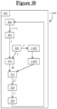
- FIG. 10 Power supply process 1000
- the 1000 power supply process is the same as that of the figure 3 , except for the following differences.
- Steps 312 and 314 are replaced by the following steps 1002 and 1004.
- the control device 110 compares, in absolute value, the setpoint phase currents i u *, i v *, i w *.
- the setpoint phase currents are for example obtained by projecting the setpoint current vector i * onto the phase directions u, v, w.
- control device 110 determines that the phase traversed by the smallest set phase current, in absolute value, is to be disconnected.
- the electric motor could have more than three phases.
- the inverter could belong to a combined electrical power supply and charging device as described in the applications FR 2 938 711 Or FR 2 944 391 .
- the phase currents could be obtained by means other than a sensor, for example by a device for estimating these currents, for example from the position of the rotor.
- control device could comprise, instead of a computer program, dedicated electronic systems for carrying out the steps of the methods described.
- the angular sectors each have an angle of at least 1° so that the disconnections have a noticeable effect.
Landscapes
- Engineering & Computer Science (AREA)
- Power Engineering (AREA)
- Control Of Ac Motors In General (AREA)
- Inverter Devices (AREA)
Applications Claiming Priority (2)
| Application Number | Priority Date | Filing Date | Title |
|---|---|---|---|
| FR1353575A FR3004871B1 (fr) | 2013-04-19 | 2013-04-19 | Procede d'alimentation electrique d'un moteur electrique, programme d'ordinateur associe, dispositif de commande d'un onduleur et machine tournante electrique |
| PCT/FR2014/050953 WO2014170619A1 (fr) | 2013-04-19 | 2014-04-18 | Procédé d'alimentation électrique d'un moteur électrique, programme d'ordinateur associé, dispositif de commande d'un onduleur et machine tournante électrique |
Publications (2)
| Publication Number | Publication Date |
|---|---|
| EP2987236A1 EP2987236A1 (fr) | 2016-02-24 |
| EP2987236B1 true EP2987236B1 (fr) | 2024-11-20 |
Family
ID=49111330
Family Applications (1)
| Application Number | Title | Priority Date | Filing Date |
|---|---|---|---|
| EP14727580.4A Active EP2987236B1 (fr) | 2013-04-19 | 2014-04-18 | Procédé d'alimentation électrique d'un moteur électrique, programme d'ordinateur associé, dispositif de commande d'un onduleur et machine tournante électrique |
Country Status (7)
| Country | Link |
|---|---|
| US (1) | US10044300B2 (https=) |
| EP (1) | EP2987236B1 (https=) |
| JP (1) | JP6915986B2 (https=) |
| KR (1) | KR102318272B1 (https=) |
| CN (1) | CN105284042B (https=) |
| FR (1) | FR3004871B1 (https=) |
| WO (1) | WO2014170619A1 (https=) |
Families Citing this family (2)
| Publication number | Priority date | Publication date | Assignee | Title |
|---|---|---|---|---|
| WO2019141346A1 (en) * | 2018-01-16 | 2019-07-25 | Abb Schweiz Ag | A method for controlling a synchronous double stator electric machine |
| US10804815B1 (en) * | 2019-07-18 | 2020-10-13 | Ford Global Technologies, Llc | DC/AC inverter system supplied by integrated power networks to increase output power with robust auto stop control |
Family Cites Families (19)
| Publication number | Priority date | Publication date | Assignee | Title |
|---|---|---|---|---|
| JPS57160384A (en) * | 1981-03-26 | 1982-10-02 | Secoh Giken Inc | Torque ripple eliminator device for direct current motor |
| US4645991A (en) * | 1981-03-22 | 1987-02-24 | Itsuki Ban | Apparatus for removing torque ripples in direct-current motors |
| JPS59226682A (ja) * | 1983-06-02 | 1984-12-19 | Fuji Electric Co Ltd | 電流ベクトル位相検出方式 |
| JPH0279792A (ja) * | 1988-09-12 | 1990-03-20 | Secoh Giken Inc | 高速3相直流電動機 |
| JPH04172986A (ja) * | 1990-11-07 | 1992-06-19 | Secoh Giken Inc | 高速3相直流電動機 |
| JP4161436B2 (ja) * | 1998-12-04 | 2008-10-08 | 松下電器産業株式会社 | インバータ装置 |
| US6888280B2 (en) * | 1999-04-01 | 2005-05-03 | Jean-Yves Dubé | High performance brushless motor and drive for an electrical vehicle motorization |
| DE60029747D1 (de) * | 2000-03-31 | 2006-09-14 | St Microelectronics Srl | Regelungsverfahren für den Stromfluss des Antriebssystems für bürstenlose Motoren, insbesondere während der Schaltphasen |
| JP3877042B2 (ja) * | 2000-06-15 | 2007-02-07 | 東洋電機製造株式会社 | 補助共振回路 |
| JP4150883B2 (ja) * | 2002-02-22 | 2008-09-17 | サンケン電気株式会社 | 3相電力変換装置 |
| JP4438417B2 (ja) * | 2004-01-13 | 2010-03-24 | トヨタ自動車株式会社 | 交流電圧発生装置および動力出力装置 |
| JP2005304255A (ja) * | 2004-04-15 | 2005-10-27 | Nsk Ltd | モータ駆動回路 |
| JP2006223097A (ja) * | 2006-04-21 | 2006-08-24 | Mitsubishi Electric Corp | 永久磁石形モータ、永久磁石形モータの制御方法、永久磁石形モータの制御装置、圧縮機、冷凍・空調装置。 |
| JP2010057256A (ja) * | 2008-08-27 | 2010-03-11 | Canon Inc | モータ駆動装置 |
| FR2944391B1 (fr) * | 2008-11-18 | 2013-03-22 | Valeo Sys Controle Moteur Sas | Procede et dispositif electrique combine d'alimentation et de charge a moyens de compensation |
| FR2938711B1 (fr) * | 2008-11-18 | 2012-12-14 | Valeo Sys Controle Moteur Sas | Dispositif electrique combine d'alimentation et de charge |
| JP2011211832A (ja) * | 2010-03-30 | 2011-10-20 | Renesas Electronics Corp | ブラシレスdcモータの駆動装置および駆動方法 |
| JP5321614B2 (ja) * | 2011-02-28 | 2013-10-23 | 株式会社デンソー | 回転機の制御装置 |
| FR2974466B1 (fr) * | 2011-04-19 | 2013-12-20 | Valeo Sys Controle Moteur Sas | Procede de commande d'un moteur electrique et dispositif electrique correspondant |
-
2013
- 2013-04-19 FR FR1353575A patent/FR3004871B1/fr active Active
-
2014
- 2014-04-18 WO PCT/FR2014/050953 patent/WO2014170619A1/fr not_active Ceased
- 2014-04-18 US US14/785,562 patent/US10044300B2/en active Active
- 2014-04-18 JP JP2016508224A patent/JP6915986B2/ja active Active
- 2014-04-18 KR KR1020157032967A patent/KR102318272B1/ko active Active
- 2014-04-18 CN CN201480032874.3A patent/CN105284042B/zh active Active
- 2014-04-18 EP EP14727580.4A patent/EP2987236B1/fr active Active
Also Published As
| Publication number | Publication date |
|---|---|
| JP2016515798A (ja) | 2016-05-30 |
| WO2014170619A1 (fr) | 2014-10-23 |
| EP2987236A1 (fr) | 2016-02-24 |
| KR102318272B1 (ko) | 2021-10-26 |
| FR3004871B1 (fr) | 2017-01-13 |
| FR3004871A1 (fr) | 2014-10-24 |
| KR20160008193A (ko) | 2016-01-21 |
| CN105284042B (zh) | 2019-06-11 |
| JP6915986B2 (ja) | 2021-08-11 |
| US20170179858A1 (en) | 2017-06-22 |
| CN105284042A (zh) | 2016-01-27 |
| US10044300B2 (en) | 2018-08-07 |
Similar Documents
| Publication | Publication Date | Title |
|---|---|---|
| EP2246973B1 (fr) | Procédé de détermination de la position du vecteur de flux d'un moteur | |
| FR2901647A1 (fr) | Dispositif et procede de commande de puissance pour une machine dynamo electrique du type a enroulement de champ | |
| EP1766422B1 (fr) | Procede de mesure du courant electrique dans une pluralite de conducteurs | |
| FR2840275A1 (fr) | Dispositif de detection d'anomalie de moteur et systeme de commande de direction a assistance electrique | |
| EP1609226B1 (fr) | Machine electrique synchrone comportant un stator et au moins un retor et dispositif de commande associe | |
| FR2897730A1 (fr) | Poursuite de position de rotor de machine synchrone a enroulement de champ sans balai avec poursuite d'harmonique de courant statorique de circuit d'excitation | |
| FR2894735A1 (fr) | Generateur-moteur synchrone a enroulement de champ | |
| FR2855677A1 (fr) | Circuit de commande a modulation en largeur d'impulsions pour machine electrique multi mode et machine electrique multi mode equipee d'un tel circuit de commande | |
| FR2820894A1 (fr) | Dispositif de commande de moteur | |
| EP2294688A1 (fr) | Procédé de détermination des inductances d'une machine synchrone a aimants permanents | |
| EP1020019A1 (fr) | Procede et dispositif de commande d'un moteur synchrone a aimant permanent | |
| EP1398869B1 (fr) | Procédé et calculateur de détermination de la position angulaire à l'arrêt d'un rotor, unité de commande et système incorporant ce calculateur. | |
| EP2987236B1 (fr) | Procédé d'alimentation électrique d'un moteur électrique, programme d'ordinateur associé, dispositif de commande d'un onduleur et machine tournante électrique | |
| FR2917917B1 (fr) | Detection de position d'un rotor a l'arret et a vitesse reduite | |
| FR2682920A1 (fr) | Chaine de traction electrique integrant la fonction moteur/generateur frein avec la fonction chargeur et/ou convertisseur. | |
| EP2790315B1 (fr) | Système d'entraînement rotatif, procédé de commande d'un onduleur et programme d'ordinateur associé | |
| EP2992585B1 (fr) | Systeme et procede de charge de la batterie d'un vehicule electrique ou hybride | |
| EP1972051A1 (fr) | Procede de determination de la position d'un rotor d'une machine synchrone muni d'au moins un enroulement d'excitation | |
| FR2930299A1 (fr) | Dispositif de demarrage de moteur d'un vehicule | |
| EP3657664B1 (fr) | Procede de commande d'une machine electrique triphasee | |
| EP2787632B1 (fr) | Procédé et dispositif de pilotage d'une machine électrique tournante double triphasée et machine électrique tournante correspondante | |
| EP2852050B1 (fr) | Méthode et dispositif de génération de n (n>=3) signaux de commande pour commander un onduleur à n phases | |
| EP4128521B1 (fr) | Procédé de commande d'un redresseur connecté à une génératrice électrique synchrone à aimants permanents pour fournir une tension continue, programme d'ordinateur et dispositif correspondant | |
| FR3135845A1 (fr) | Dispositif de contrôle pour une machine tournante triphasée synchrone à aimants permanents | |
| FR2897211A1 (fr) | Dispositif de commande de moteur de vehicule automobile |
Legal Events
| Date | Code | Title | Description |
|---|---|---|---|
| PUAI | Public reference made under article 153(3) epc to a published international application that has entered the european phase |
Free format text: ORIGINAL CODE: 0009012 |
|
| 17P | Request for examination filed |
Effective date: 20151015 |
|
| AK | Designated contracting states |
Kind code of ref document: A1 Designated state(s): AL AT BE BG CH CY CZ DE DK EE ES FI FR GB GR HR HU IE IS IT LI LT LU LV MC MK MT NL NO PL PT RO RS SE SI SK SM TR |
|
| AX | Request for extension of the european patent |
Extension state: BA ME |
|
| RIN1 | Information on inventor provided before grant (corrected) |
Inventor name: OSWALD, DOMINIQUE |
|
| DAX | Request for extension of the european patent (deleted) | ||
| STAA | Information on the status of an ep patent application or granted ep patent |
Free format text: STATUS: EXAMINATION IS IN PROGRESS |
|
| 17Q | First examination report despatched |
Effective date: 20180706 |
|
| GRAP | Despatch of communication of intention to grant a patent |
Free format text: ORIGINAL CODE: EPIDOSNIGR1 |
|
| STAA | Information on the status of an ep patent application or granted ep patent |
Free format text: STATUS: GRANT OF PATENT IS INTENDED |
|
| INTG | Intention to grant announced |
Effective date: 20240612 |
|
| RAP1 | Party data changed (applicant data changed or rights of an application transferred) |
Owner name: VALEO ELECTRIFICATION |
|
| GRAS | Grant fee paid |
Free format text: ORIGINAL CODE: EPIDOSNIGR3 |
|
| GRAA | (expected) grant |
Free format text: ORIGINAL CODE: 0009210 |
|
| STAA | Information on the status of an ep patent application or granted ep patent |
Free format text: STATUS: THE PATENT HAS BEEN GRANTED |
|
| AK | Designated contracting states |
Kind code of ref document: B1 Designated state(s): AL AT BE BG CH CY CZ DE DK EE ES FI FR GB GR HR HU IE IS IT LI LT LU LV MC MK MT NL NO PL PT RO RS SE SI SK SM TR |
|
| REG | Reference to a national code |
Ref country code: GB Ref legal event code: FG4D Free format text: NOT ENGLISH |
|
| REG | Reference to a national code |
Ref country code: CH Ref legal event code: EP |
|
| REG | Reference to a national code |
Ref country code: DE Ref legal event code: R096 Ref document number: 602014091198 Country of ref document: DE |
|
| REG | Reference to a national code |
Ref country code: IE Ref legal event code: FG4D Free format text: LANGUAGE OF EP DOCUMENT: FRENCH |
|
| REG | Reference to a national code |
Ref country code: LT Ref legal event code: MG9D |
|
| REG | Reference to a national code |
Ref country code: NL Ref legal event code: MP Effective date: 20241120 |
|
| PG25 | Lapsed in a contracting state [announced via postgrant information from national office to epo] |
Ref country code: HR Free format text: LAPSE BECAUSE OF FAILURE TO SUBMIT A TRANSLATION OF THE DESCRIPTION OR TO PAY THE FEE WITHIN THE PRESCRIBED TIME-LIMIT Effective date: 20241120 Ref country code: PT Free format text: LAPSE BECAUSE OF FAILURE TO SUBMIT A TRANSLATION OF THE DESCRIPTION OR TO PAY THE FEE WITHIN THE PRESCRIBED TIME-LIMIT Effective date: 20250320 Ref country code: IS Free format text: LAPSE BECAUSE OF FAILURE TO SUBMIT A TRANSLATION OF THE DESCRIPTION OR TO PAY THE FEE WITHIN THE PRESCRIBED TIME-LIMIT Effective date: 20250320 |
|
| PG25 | Lapsed in a contracting state [announced via postgrant information from national office to epo] |
Ref country code: FI Free format text: LAPSE BECAUSE OF FAILURE TO SUBMIT A TRANSLATION OF THE DESCRIPTION OR TO PAY THE FEE WITHIN THE PRESCRIBED TIME-LIMIT Effective date: 20241120 Ref country code: NL Free format text: LAPSE BECAUSE OF FAILURE TO SUBMIT A TRANSLATION OF THE DESCRIPTION OR TO PAY THE FEE WITHIN THE PRESCRIBED TIME-LIMIT Effective date: 20241120 |
|
| REG | Reference to a national code |
Ref country code: AT Ref legal event code: MK05 Ref document number: 1744484 Country of ref document: AT Kind code of ref document: T Effective date: 20241120 |
|
| PG25 | Lapsed in a contracting state [announced via postgrant information from national office to epo] |
Ref country code: BG Free format text: LAPSE BECAUSE OF FAILURE TO SUBMIT A TRANSLATION OF THE DESCRIPTION OR TO PAY THE FEE WITHIN THE PRESCRIBED TIME-LIMIT Effective date: 20241120 |
|
| PG25 | Lapsed in a contracting state [announced via postgrant information from national office to epo] |
Ref country code: ES Free format text: LAPSE BECAUSE OF FAILURE TO SUBMIT A TRANSLATION OF THE DESCRIPTION OR TO PAY THE FEE WITHIN THE PRESCRIBED TIME-LIMIT Effective date: 20241120 |
|
| PG25 | Lapsed in a contracting state [announced via postgrant information from national office to epo] |
Ref country code: NO Free format text: LAPSE BECAUSE OF FAILURE TO SUBMIT A TRANSLATION OF THE DESCRIPTION OR TO PAY THE FEE WITHIN THE PRESCRIBED TIME-LIMIT Effective date: 20250220 |
|
| PG25 | Lapsed in a contracting state [announced via postgrant information from national office to epo] |
Ref country code: GR Free format text: LAPSE BECAUSE OF FAILURE TO SUBMIT A TRANSLATION OF THE DESCRIPTION OR TO PAY THE FEE WITHIN THE PRESCRIBED TIME-LIMIT Effective date: 20250221 Ref country code: AT Free format text: LAPSE BECAUSE OF FAILURE TO SUBMIT A TRANSLATION OF THE DESCRIPTION OR TO PAY THE FEE WITHIN THE PRESCRIBED TIME-LIMIT Effective date: 20241120 Ref country code: LV Free format text: LAPSE BECAUSE OF FAILURE TO SUBMIT A TRANSLATION OF THE DESCRIPTION OR TO PAY THE FEE WITHIN THE PRESCRIBED TIME-LIMIT Effective date: 20241120 |
|
| PG25 | Lapsed in a contracting state [announced via postgrant information from national office to epo] |
Ref country code: PL Free format text: LAPSE BECAUSE OF FAILURE TO SUBMIT A TRANSLATION OF THE DESCRIPTION OR TO PAY THE FEE WITHIN THE PRESCRIBED TIME-LIMIT Effective date: 20241120 |
|
| PG25 | Lapsed in a contracting state [announced via postgrant information from national office to epo] |
Ref country code: RS Free format text: LAPSE BECAUSE OF FAILURE TO SUBMIT A TRANSLATION OF THE DESCRIPTION OR TO PAY THE FEE WITHIN THE PRESCRIBED TIME-LIMIT Effective date: 20250220 |
|
| PG25 | Lapsed in a contracting state [announced via postgrant information from national office to epo] |
Ref country code: SM Free format text: LAPSE BECAUSE OF FAILURE TO SUBMIT A TRANSLATION OF THE DESCRIPTION OR TO PAY THE FEE WITHIN THE PRESCRIBED TIME-LIMIT Effective date: 20241120 |
|
| PGFP | Annual fee paid to national office [announced via postgrant information from national office to epo] |
Ref country code: DE Payment date: 20250411 Year of fee payment: 12 |
|
| PG25 | Lapsed in a contracting state [announced via postgrant information from national office to epo] |
Ref country code: DK Free format text: LAPSE BECAUSE OF FAILURE TO SUBMIT A TRANSLATION OF THE DESCRIPTION OR TO PAY THE FEE WITHIN THE PRESCRIBED TIME-LIMIT Effective date: 20241120 |
|
| PG25 | Lapsed in a contracting state [announced via postgrant information from national office to epo] |
Ref country code: EE Free format text: LAPSE BECAUSE OF FAILURE TO SUBMIT A TRANSLATION OF THE DESCRIPTION OR TO PAY THE FEE WITHIN THE PRESCRIBED TIME-LIMIT Effective date: 20241120 |
|
| PGFP | Annual fee paid to national office [announced via postgrant information from national office to epo] |
Ref country code: FR Payment date: 20250429 Year of fee payment: 12 |
|
| PG25 | Lapsed in a contracting state [announced via postgrant information from national office to epo] |
Ref country code: RO Free format text: LAPSE BECAUSE OF FAILURE TO SUBMIT A TRANSLATION OF THE DESCRIPTION OR TO PAY THE FEE WITHIN THE PRESCRIBED TIME-LIMIT Effective date: 20241120 |
|
| PG25 | Lapsed in a contracting state [announced via postgrant information from national office to epo] |
Ref country code: SK Free format text: LAPSE BECAUSE OF FAILURE TO SUBMIT A TRANSLATION OF THE DESCRIPTION OR TO PAY THE FEE WITHIN THE PRESCRIBED TIME-LIMIT Effective date: 20241120 |
|
| PG25 | Lapsed in a contracting state [announced via postgrant information from national office to epo] |
Ref country code: CZ Free format text: LAPSE BECAUSE OF FAILURE TO SUBMIT A TRANSLATION OF THE DESCRIPTION OR TO PAY THE FEE WITHIN THE PRESCRIBED TIME-LIMIT Effective date: 20241120 |
|
| PG25 | Lapsed in a contracting state [announced via postgrant information from national office to epo] |
Ref country code: IT Free format text: LAPSE BECAUSE OF FAILURE TO SUBMIT A TRANSLATION OF THE DESCRIPTION OR TO PAY THE FEE WITHIN THE PRESCRIBED TIME-LIMIT Effective date: 20241120 |
|
| REG | Reference to a national code |
Ref country code: DE Ref legal event code: R097 Ref document number: 602014091198 Country of ref document: DE |
|
| PG25 | Lapsed in a contracting state [announced via postgrant information from national office to epo] |
Ref country code: SE Free format text: LAPSE BECAUSE OF FAILURE TO SUBMIT A TRANSLATION OF THE DESCRIPTION OR TO PAY THE FEE WITHIN THE PRESCRIBED TIME-LIMIT Effective date: 20241120 |
|
| PLBE | No opposition filed within time limit |
Free format text: ORIGINAL CODE: 0009261 |
|
| STAA | Information on the status of an ep patent application or granted ep patent |
Free format text: STATUS: NO OPPOSITION FILED WITHIN TIME LIMIT |
|
| 26N | No opposition filed |
Effective date: 20250821 |
|
| REG | Reference to a national code |
Ref country code: CH Ref legal event code: H13 Free format text: ST27 STATUS EVENT CODE: U-0-0-H10-H13 (AS PROVIDED BY THE NATIONAL OFFICE) Effective date: 20251125 |
|
| PG25 | Lapsed in a contracting state [announced via postgrant information from national office to epo] |
Ref country code: LU Free format text: LAPSE BECAUSE OF NON-PAYMENT OF DUE FEES Effective date: 20250418 |
|
| PG25 | Lapsed in a contracting state [announced via postgrant information from national office to epo] |
Ref country code: MC Free format text: LAPSE BECAUSE OF FAILURE TO SUBMIT A TRANSLATION OF THE DESCRIPTION OR TO PAY THE FEE WITHIN THE PRESCRIBED TIME-LIMIT Effective date: 20241120 |
|
| GBPC | Gb: european patent ceased through non-payment of renewal fee |
Effective date: 20250418 |
|
| REG | Reference to a national code |
Ref country code: BE Ref legal event code: MM Effective date: 20250430 |
|
| PG25 | Lapsed in a contracting state [announced via postgrant information from national office to epo] |
Ref country code: GB Free format text: LAPSE BECAUSE OF NON-PAYMENT OF DUE FEES Effective date: 20250418 |
|
| PG25 | Lapsed in a contracting state [announced via postgrant information from national office to epo] |
Ref country code: BE Free format text: LAPSE BECAUSE OF NON-PAYMENT OF DUE FEES Effective date: 20250430 |
|
| PG25 | Lapsed in a contracting state [announced via postgrant information from national office to epo] |
Ref country code: CH Free format text: LAPSE BECAUSE OF NON-PAYMENT OF DUE FEES Effective date: 20250430 |
|
| PG25 | Lapsed in a contracting state [announced via postgrant information from national office to epo] |
Ref country code: IE Free format text: LAPSE BECAUSE OF NON-PAYMENT OF DUE FEES Effective date: 20250418 |