EP2987173B1 - Supraleitende spuleneinrichtung mit spulenwicklung und herstellungsverfahren - Google Patents
Supraleitende spuleneinrichtung mit spulenwicklung und herstellungsverfahren Download PDFInfo
- Publication number
- EP2987173B1 EP2987173B1 EP14729237.9A EP14729237A EP2987173B1 EP 2987173 B1 EP2987173 B1 EP 2987173B1 EP 14729237 A EP14729237 A EP 14729237A EP 2987173 B1 EP2987173 B1 EP 2987173B1
- Authority
- EP
- European Patent Office
- Prior art keywords
- winding
- strip conductor
- contact
- conductor
- coil
- Prior art date
- Legal status (The legal status is an assumption and is not a legal conclusion. Google has not performed a legal analysis and makes no representation as to the accuracy of the status listed.)
- Not-in-force
Links
- 238000004804 winding Methods 0.000 title claims description 148
- 238000004519 manufacturing process Methods 0.000 title claims description 17
- 239000004020 conductor Substances 0.000 claims description 152
- 238000000034 method Methods 0.000 claims description 12
- 150000001875 compounds Chemical class 0.000 claims description 8
- 239000000853 adhesive Substances 0.000 claims description 6
- 230000001070 adhesive effect Effects 0.000 claims description 6
- 238000005266 casting Methods 0.000 claims description 3
- 238000012856 packing Methods 0.000 claims 4
- 230000008901 benefit Effects 0.000 description 20
- 239000000945 filler Substances 0.000 description 18
- 239000000463 material Substances 0.000 description 14
- 239000010949 copper Substances 0.000 description 12
- 239000000758 substrate Substances 0.000 description 10
- RYGMFSIKBFXOCR-UHFFFAOYSA-N Copper Chemical compound [Cu] RYGMFSIKBFXOCR-UHFFFAOYSA-N 0.000 description 7
- 229910052802 copper Inorganic materials 0.000 description 7
- 239000012212 insulator Substances 0.000 description 6
- 238000011161 development Methods 0.000 description 5
- 230000018109 developmental process Effects 0.000 description 5
- 229910000679 solder Inorganic materials 0.000 description 5
- 238000005476 soldering Methods 0.000 description 4
- 241000954177 Bangana ariza Species 0.000 description 3
- 238000003780 insertion Methods 0.000 description 3
- 230000037431 insertion Effects 0.000 description 3
- 238000004382 potting Methods 0.000 description 3
- 239000002887 superconductor Substances 0.000 description 3
- 229910000831 Steel Inorganic materials 0.000 description 2
- 229910045601 alloy Inorganic materials 0.000 description 2
- 239000000956 alloy Substances 0.000 description 2
- 238000005452 bending Methods 0.000 description 2
- 230000015572 biosynthetic process Effects 0.000 description 2
- 238000010276 construction Methods 0.000 description 2
- 238000001816 cooling Methods 0.000 description 2
- 230000001419 dependent effect Effects 0.000 description 2
- 229920006332 epoxy adhesive Polymers 0.000 description 2
- 239000011152 fibreglass Substances 0.000 description 2
- 229910000856 hastalloy Inorganic materials 0.000 description 2
- 239000010959 steel Substances 0.000 description 2
- 230000001360 synchronised effect Effects 0.000 description 2
- BQCADISMDOOEFD-UHFFFAOYSA-N Silver Chemical compound [Ag] BQCADISMDOOEFD-UHFFFAOYSA-N 0.000 description 1
- 239000004809 Teflon Substances 0.000 description 1
- 229920006362 Teflon® Polymers 0.000 description 1
- 229910001080 W alloy Inorganic materials 0.000 description 1
- 238000005520 cutting process Methods 0.000 description 1
- 230000032798 delamination Effects 0.000 description 1
- 230000002349 favourable effect Effects 0.000 description 1
- 230000020169 heat generation Effects 0.000 description 1
- 239000011810 insulating material Substances 0.000 description 1
- 238000009413 insulation Methods 0.000 description 1
- 239000000203 mixture Substances 0.000 description 1
- MOWMLACGTDMJRV-UHFFFAOYSA-N nickel tungsten Chemical compound [Ni].[W] MOWMLACGTDMJRV-UHFFFAOYSA-N 0.000 description 1
- 239000004033 plastic Substances 0.000 description 1
- 229920003023 plastic Polymers 0.000 description 1
- 229920003223 poly(pyromellitimide-1,4-diphenyl ether) Polymers 0.000 description 1
- 230000000750 progressive effect Effects 0.000 description 1
- 229910052761 rare earth metal Inorganic materials 0.000 description 1
- 230000011218 segmentation Effects 0.000 description 1
- 229910052709 silver Inorganic materials 0.000 description 1
- 239000004332 silver Substances 0.000 description 1
- 125000006850 spacer group Chemical group 0.000 description 1
- 230000006641 stabilisation Effects 0.000 description 1
- 238000011105 stabilization Methods 0.000 description 1
- 230000007704 transition Effects 0.000 description 1
- 238000009827 uniform distribution Methods 0.000 description 1
- 238000004046 wet winding Methods 0.000 description 1
Images

Classifications
-
- H—ELECTRICITY
- H01—ELECTRIC ELEMENTS
- H01F—MAGNETS; INDUCTANCES; TRANSFORMERS; SELECTION OF MATERIALS FOR THEIR MAGNETIC PROPERTIES
- H01F6/00—Superconducting magnets; Superconducting coils
- H01F6/06—Coils, e.g. winding, insulating, terminating or casing arrangements therefor
-
- H—ELECTRICITY
- H01—ELECTRIC ELEMENTS
- H01F—MAGNETS; INDUCTANCES; TRANSFORMERS; SELECTION OF MATERIALS FOR THEIR MAGNETIC PROPERTIES
- H01F41/00—Apparatus or processes specially adapted for manufacturing or assembling magnets, inductances or transformers; Apparatus or processes specially adapted for manufacturing materials characterised by their magnetic properties
- H01F41/02—Apparatus or processes specially adapted for manufacturing or assembling magnets, inductances or transformers; Apparatus or processes specially adapted for manufacturing materials characterised by their magnetic properties for manufacturing cores, coils, or magnets
- H01F41/04—Apparatus or processes specially adapted for manufacturing or assembling magnets, inductances or transformers; Apparatus or processes specially adapted for manufacturing materials characterised by their magnetic properties for manufacturing cores, coils, or magnets for manufacturing coils
- H01F41/048—Superconductive coils
-
- H—ELECTRICITY
- H01—ELECTRIC ELEMENTS
- H01F—MAGNETS; INDUCTANCES; TRANSFORMERS; SELECTION OF MATERIALS FOR THEIR MAGNETIC PROPERTIES
- H01F41/00—Apparatus or processes specially adapted for manufacturing or assembling magnets, inductances or transformers; Apparatus or processes specially adapted for manufacturing materials characterised by their magnetic properties
- H01F41/02—Apparatus or processes specially adapted for manufacturing or assembling magnets, inductances or transformers; Apparatus or processes specially adapted for manufacturing materials characterised by their magnetic properties for manufacturing cores, coils, or magnets
- H01F41/04—Apparatus or processes specially adapted for manufacturing or assembling magnets, inductances or transformers; Apparatus or processes specially adapted for manufacturing materials characterised by their magnetic properties for manufacturing cores, coils, or magnets for manufacturing coils
- H01F41/06—Coil winding
- H01F41/064—Winding non-flat conductive wires, e.g. rods, cables or cords
- H01F41/069—Winding two or more wires, e.g. bifilar winding
- H01F41/07—Twisting
Definitions
- the present invention relates to a superconductive coil device having at least one multi-turn coil winding of a superconducting tape conductor. Furthermore, the invention relates to a manufacturing method for such a superconducting coil device.
- HTS high-temperature superconductors or even high-T c superconductors
- band conductors often have further layers such as stabilization layers, contact layers, buffer layers and in some cases also insulation layers.
- the most important material class of the so-called second-generation HTS conductors (2G-HTS) are compounds of the type REBa 2 Cu 3 O x , where RE stands for a rare-earth element or a mixture of such elements.
- the substrate tape is typically either steel or alloy Hastelloy.
- the electrical contact to an external circuit is usually made via a contact layer of copper, wherein this contact layer is either applied on one side over the superconducting layer or can surround the entire band conductor as an enveloping layer. In both versions, it is better to contact on the Side of the substrate strip, which carries the superconducting layer. This page of the strip conductor is referred to below as the contact page.
- a filler such as Teflon must be used first to keep the point to be contacted of adhesive free. After removal of the filler can be made for contacting this point, for example, a solder joint to a contact piece of copper. But since this contact is within the winding, the contact area must be subsequently fixed with bandages of glass fiber reinforced plastic and epoxy adhesive to produce the necessary mechanical stability.
- a superconducting coil winding is provided with at least two strip conductors, each having a contact side exhibit.
- the first and the second band conductors are electrically connected via an inner contact between their contact sides.
- the first and the second band conductors differ in their orientation with respect to the center of the coil, so that the orientation of the contact side is turned through this inner contact. This allows a freely accessible contacting the contact side both on the inside and on the outside of the coil winding.
- the disadvantage of the coil winding specified there, however, is that the additional inner contact creates a further normally conducting connection within the coil, so that the superconducting properties of the coil are interrupted in its interior, and there electrical losses associated with higher heat generation occur.
- Object of the present invention is to provide a coil device which avoids the disadvantages mentioned. Another object is to provide a method for producing such a coil device.
- the coil device comprises at least one coil winding with at least one winding of at least one superconducting strip conductor.
- the strip conductor has a first conductor surface, which is designed as a contact side and is provided with a contact layer.
- the tape conductor is twisted about a longitudinal axis of the tape conductor by at least one turn in a torsion region about 180 degrees, and the contact side of the tape conductor faces an inner side of the winding toward a center of the winding and faces away from the center of the winding on an outer side of the winding.
- the torsion of the strip conductor about its longitudinal axis within the coil winding is achieved that in a simple winding of typically a plurality of surface superimposed windings both on the inside of the winding and on the outside of the winding, the side of the strip conductor with the low-resistance contact with the superconducting Layer comes to lie outside.
- unnecessary additional torsion within the winding of a superconducting tape conductor is rather avoided, since such a torsion can lead to internal stresses of the layer materials up to the delamination and the loss of the superconducting properties.
- the superconducting coil means may comprise HTS materials of the second generation, in particular the above-mentioned compounds of the type REBa 2 Cu 3 O x .
- Second generation HTS materials are also advantageous because they have higher tensile strength and higher critical current density than first generation HTS materials.
- a significant advantage compared to the solution disclosed in 102012223366.0 is that no additional normal conducting soldering must be introduced into the winding.
- the entire coil winding may be formed with either one or more parallel superconducting conductive tracks which may extend over the entire radial area of the coil winding.
- the individual strip conductors of the stack can either be twisted one at a time sequentially or they can be twisted as a whole in the form of the entire stack.
- the coil device according to the invention comprises a coil winding with a plurality of turns, but also applications are possible in which the advantage according to the invention of the torsion of the strip conductor already comes into play in a single turn.
- a superconducting strip conductor is wound in several turns on a winding support.
- the strip conductor has a first conductor surface, which is designed as a contact side and is provided with a contact layer.
- the contact side of the strip conductor is at the beginning of the winding to the winding support and thus facing a center of the winding.
- the strip conductor is twisted about a longitudinal axis of the strip conductor by at least one of the turns in a torsion region about 180 degrees, and the contact side of the strip conductor faces away from the center of the winding on an outside of the winding.
- the advantages of the manufacturing process are partly analogous to the advantages of the superconducting coil device according to the invention. Further advantages are in the simplified manufacturing process compared to the production of a coil device with an additional inner contact for changing the orientation of the strip conductor. In a twist of the strip conductor by torsion, on the one hand, the additional process step for producing the inner contact connection is avoided.
- the winding can be done with a higher winding tension, if not mechanically sensitive internal soldering contact is present.
- the winding process can also be carried out more easily and faster if only a single strip conductor or a package of parallel strip conductors has to be wound without additional internal soldering contact. Above all, the winding process is easier because no additional preparatory process steps are necessary without an internal soldering contact. In particular, no additional Umspulariae to provide the wound strip conductor or the package to be wrapped several band conductor on a supply reel necessary.
- the coil device may additionally comprise the following features:
- the superconductive coil device may comprise a first contact between the contact side of the strip conductor and an inner contact piece on an inner side of the coil winding and a second contact between the contact side of the strip conductor and an outer contact piece on an outer side of the coil winding for connecting the coil device to an outer circuit.
- the inside of the coil winding faces a center of the coil winding, and the outside of the coil winding is remote from the center of the coil winding.
- the first and second contacts with the inner and outer contacts serve to connect the coil means to an external circuit.
- these contacts are executed as low as possible, and the contacts suitably comprise conductive materials as possible with a high geometric cross-section for power transport.
- the inner and outer contacts may comprise copper.
- the advantage of this embodiment is that in this way the contacts to the two contact pieces can be created on freely accessible sides of the coil winding.
- no temporary filler pieces have to be inserted into the winding during the production of the coil winding, which subsequently have to be removed again, to make room for a to be introduced in a gap of the winding contact piece.
- the high space requirement for such a placeholder is eliminated as well as the space required for a contact within the winding. This results in a higher effective current density within the winding.
- Another advantage of the freely accessible contact points to create the contacts to the contact pieces is that under less confined spaces easier enough a low-resistance and reliable solder joint between the contact piece and contact side of the strip conductor can be created.
- a further power supply from an external circuit to the contact pieces is simplified because the contact pieces can be easily connected to an external power connection even on the freely accessible sides of the coil winding.
- the strip conductor may have two conductor surfaces, and the coil device may comprise at least two patches which are respectively adjacent to one of the conductor surfaces of the strip conductor in the torsion region of the at least one twisted turn such that the patches largely fill spaces due to the torsion between adjacent turns.
- the advantage of this embodiment is that the mechanical stability of the resulting coil winding is increased because the band conductor is held firmly by the at least two filler pieces. The mechanical stability is increased on the one hand during winding of the coil, so that during production, a larger winding tension can be used without the band conductor in the region of the torsion zone to harm. On the other hand, the mechanical stability during operation of the superconducting coil is also improved by the filler pieces.
- Superconducting coils can be exposed during their operation strong centrifugal forces, for example by rotation in generators or machines. Alternatively or additionally, they may also be exposed to high Lorentz forces when generating strong magnetic fields. To protect against damage to the strip conductor under such loads, it is expedient to hold the strip conductor on both sides even in the torsion region of the winding and to protect against unnecessary tensile or shear forces and vibrations. The use of two separate patches is therefore expedient because the twisted band conductor itself divides the cavity formed by the torsion in the coil winding into two approximately equal and non-contiguous parts.
- Each of the two aforementioned filling pieces may comprise an inner and an outer portion, wherein the respective inner portion is arranged on a locally centered side of the twisted band conductor and the respective outer portion is arranged on a side facing away from the center of the twisted band conductor locally.
- Such a division of the filler into at least two sections is advantageous because the two conductor surfaces of the strip conductor change by the torsion each from the inside to the outside or vice versa. Since it is difficult to position an elongated filler simultaneously above and below the turn of a ribbon conductor in the manufacture of the coil, the division of each filler into at least two segments facilitates insertion into the coil to be produced.
- the torsion range of the winding can be at least three times as large along the longitudinal direction of the strip conductor as the width of the strip conductor. Particularly advantageously, the torsion range in this direction at least five times and at most ten times as large as the width of the strip conductor.
- the torsion of the strip conductor is narrower, and the individual layers of the strip conductor are subjected to greater mechanical stress by the torsion.
- the advantage of a rather small aspect ratio lies in the fact that the compactness and possibly existing symmetry of the entire coil device is disturbed only in a small partial area. It is therefore advantageous to choose the torsion zone as small as it is possible in the mechanical strength of the strip conductor used.
- the aspect ratio of the dimensions of the filler in the longitudinal direction of the strip conductor and in the direction of the conductor width is then about the same or almost as large as the abovementioned aspect ratio of the torsion region itself.
- the coil winding may comprise at least five turns, and the at least one twisted winding may be in the region of the 20% of the turns facing away from the center.
- the number of turns is advantageously much higher, for example in the range of 10 to 1000 turns.
- the torsion region of the twisted turn may be approximately diametrically opposite the region of the first contact. This is advantageous to those passing through the first contact and the torsion zone Evenly distributed asymmetry of the coil winding to distribute evenly over the winding.
- the coil winding may be formed as a flat rectangular coil with four straight sections and four rounded corners.
- a rectangular coil or racetrack coil called coil form is often used in the field of rotors of generators or synchronous machines.
- other coil shapes are possible, such as oval or cylindrical flat coils or saddle-shaped coils.
- the torsion region can be arranged centrally on one of the straight sections of the rectangular coil.
- This arrangement has the advantage that the band conductor in the torsion region is then twisted only along the longitudinal axis and at this point is not simultaneously bent within the winding plane. If there is a torsion at the same point and at the same time bending around another axis, the band conductor is subjected to more stress than a simple torsion on a straight section of the winding.
- An advantage of the uniform distribution of the torsional stress is an arrangement of the torsion region in the middle of one of the straight sections of the rectangular coil.
- the torsion region is particularly advantageously arranged on or near the intended axis of rotation of the coil.
- Such an embodiment has the advantage that only slight centrifugal forces occur in the region of the torsion zone due to the positioning on or near the axis of rotation, and thus that the mechanically somewhat more vulnerable twisted region of the strip conductor is protected against additional mechanical loads.
- the turns of the coil winding may be mechanically fixed with a potting compound and / or an adhesive.
- the resulting benefits are analogous to the advantages of using patches to fill in the cavities created by the torsion.
- the coil winding is damaged by mechanical force protected.
- Particularly advantageous is the use of filler pieces in combination with a casting of the coil winding, wherein the inserted filler is cast together with the adjacent strip conductor turns.
- a first contact between the contact side of the strip conductor and an inner contact piece can be formed only after the winding of the strip conductor, and a second contact between the contact side of the strip conductor and an outer contact piece can be formed.
- This embodiment is advantageous if the coil is to be released from the winding carrier before being put into operation and is either used as a freely supporting component without a carrier or is transferred to a separate coil carrier for operation.
- At least two filler pieces can be arranged adjacent to one of two conductor surfaces of the strip conductor in such a way that they cause interspaces due to the torsion between adjacent turns fill.
- Each of the two filler pieces may comprise an inner and an outer portion, wherein the respective inner portion is disposed on a locally centered side of the twisted strip conductor and the respective outer portion is arranged on a side facing away from the center of the twisted band conductor locally.
- the coil winding can be glued after winding and / or during winding with a potting compound and / or with an adhesive.
- the advantages of these embodiments are analogous to the advantages of claim 9.
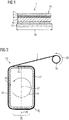
- Fig. 1 shows a cross section of a superconducting strip conductor 1, in which the layer structure is shown schematically.
- the strip conductor in this example comprises a substrate strip 2, here is a 100 micron thick substrate strip of a nickel-tungsten alloy. Alternatively, steel bands or bands of an alloy such as Hastelloy can be used.
- a 0.5 ⁇ m thick buffer layer 4 is arranged, which here contains the oxidic materials CeO 2 and Y 2 O 3 .
- the actual superconducting layer 6, here a 1 ⁇ m thick layer of YBa 2 Cu 3 O x which in turn is covered with a 50 ⁇ m thick contact layer 8 made of copper.
- the superconducting layer and the copper may additionally be a silver topcoat.
- YBa 2 Cu 3 O x As an alternative to the material YBa 2 Cu 3 O x , it is also possible to use the corresponding compounds REBa 2 Cu 3 O "of other rare earths RE
- another 50 ⁇ m thick cover layer 10 made of copper is arranged here, followed by one Insulator 12, which in this example is formed as a Kapton tape 25 microns thick, but the insulator 12 can also be made of other insulating materials such as other plastics.
- the width of the insulator 12 is slightly larger than the width of the remaining layers
- a contacting of the strip conductor 1 is advantageously possible via the contact layer 8.
- the overhead side of the strip conductor 1 is therefore also referred to as the contact side 13.
- a preferred contact side 13 is given, which is typically the side of the substrate 2, on which the superconducting layer 6 is arranged.
- FIG. 3 shows a schematic cross-section of a rectangular coil winding 15 according to the preferred embodiment of the invention. Shown is an early stage during the manufacture of the coil winding 15, in which the strip conductor 1 is wound from a supply reel 19 onto a winding support 17. In this case, both the supply reel 19 and the winding support 17 within the winding plane, which here is the cutting plane, with the in Fig. 1 marked directions of rotation turned 18 and 20.
- a first contact 23 was formed between the contact side 13 of the strip conductor and a first contact piece (not shown here for the sake of clarity).
- the first contact piece for example, consists essentially of copper and may be fixedly connected to the winding support 17 and / or integrated into it.
- the winding support 17 is in this example a cylindrical body with a rectangular cross section with rounded corners.
- the strip conductor 1 is then wound flat with the inner contact side 13 on the winding support 17.
- some turns can be formed with an initially internal contact side 13.
- Fig. 2 is shown schematically only half a turn with internal contact side 13, but this is only to be understood as an example.
- Coil windings 15 are advantageously produced with a plurality of turns, in which the contact side 13 lies on an inner side 29 of the coil winding 15. Then within a turn W t , which in Fig.
- the tape conductor 1 twisted about its local longitudinal axis 24 by about 180 degrees, so that after the torsion, the contact side 13 of the strip conductor 1 on a Outside 31 of the coil winding 15 comes to rest.
- the torsion portion 25 is arranged in this embodiment so that it comes to lie completely on one of the straight portions of the rectangular coil.
- the length 26 of the torsion zone 25 is in this example at a five times the width 30 of the strip conductor 1, so that the rotation of the strip conductor 1 does not lead to excessive mechanical stress of the layer system, the torsion region 25, however, is not extended larger than necessary.
- the axis of rotation 28 is also marked, around which the finished coil winding 15 will rotate in a later application, for example in the rotor of a synchronous machine.
- the torsion region 25 is arranged in this example symmetrically about this axis of rotation 28, so that a load on this sensitive area is largely minimized by centrifugal forces.
- two filler pieces each having two sections 33 are introduced into the resulting cavities, which mechanically support the twisted strip conductor.
- the total of four sections 33 are shaped to fill the spaces between the twisted turn W t and adjacent turns.
- the four sections 33 may fill an approximately equal volume and be configured such that each filler comprises a lower and an upper section. Of these, a respective bottom and an overhead section 33 of the contact side 13 of the twisted winding W t is adjacent, the other two sections 33 are arranged adjacent to the back of the twisted strip conductor 1 adjacent.
- Fig. 3 shows a schematic detail view of the torsion 25 of the coil winding 15.
- the upper area of the Fig. 3 is the inner side 29 of the coil winding 15 faces, and the lower portion of the outer side 31 of the coil winding 15 faces.
- the contact side 13 of the strip conductor 1 faces the center 27 of the coil.
- the contact side 13 of the strip conductor is remote from the center 27 of the coil.
- the strip conductor 1 On a portion of the length 26 of the winding W t , the strip conductor 1 is twisted about its longitudinal axis 24 by about 180 degrees. As a result, the thickness of this turn W t locally increases to a value corresponding to the width 30 of the strip conductor.
- the above and below the twisted strip conductor 1 inserted patches are sake of clarity in Fig. 3 not shown, since they would otherwise obscure the conductor surface 36 of the twisted strip conductor 1.
- the illustrated conductor surface 36 may be, for example, the contact side 13.
- Fig. 4 shows a schematic perspective view of one of the four sections 33 of the filler.
- the length of this section corresponds approximately to half the torsion length 26a.
- the illustrated section 33 includes five boundary surfaces 33a to 33e, two of which are curved surfaces 33b, 33c and three planar surfaces 33a, 33d, 33e. In this example, it is a bottom section 33 which is inserted between the twisted turn W t and the next inward turn W t-1 .
- the second associated section which is adjacent to the same conductor surface 36 of the twisted strip conductor 1, is accordingly an overhead section which is inserted between the twisted turn W t and the torsion adjacent outboard turn W t + 1 .
- the straight boundary surface 33a connects these two associated sections.
- the twisted limiting surface 33b is adjacent in the ready-wound coil conductors of the twisted surface 36 of the turn W t.
- the also curved Interface 33c is applied to the band conductor 1 of the subsequent turn W t + 1 , which is formed slightly curved by the higher space requirement in the torsion 25.
- the lower surface 33d is formed straight and adjacent to the next inner winding W t-1 .
- the interface 33e is also straight and limits the section laterally, in a direction perpendicular to the winding plane.
- the filler pieces are made in the preferred embodiment of glass fiber reinforced plastic. However, they may alternatively or additionally include other materials. Particularly suitable are those materials whose thermal shrinkage is similar to the thermal shrinkage of the remaining coil winding 15 when the coil winding 15 cools from room temperature to an operating temperature of 77 K or 25-30 K, for example.
Landscapes
- Engineering & Computer Science (AREA)
- Power Engineering (AREA)
- Manufacturing & Machinery (AREA)
- Superconductors And Manufacturing Methods Therefor (AREA)
- Manufacturing Cores, Coils, And Magnets (AREA)
Description
- Die vorliegende Erfindung betrifft eine supraleitende Spuleneinrichtung mit wenigstens einer Spulenwicklung mit mehreren Windungen eines supraleitenden Bandleiters. Weiterhin betrifft die Erfindung ein Herstellungsverfahren für eine solche supraleitende Spuleneinrichtung.
- Auf dem Gebiet der supraleitenden Maschinen und der supraleitenden Magnetspulen sind Spuleneinrichtungen bekannt, bei denen supraleitende Drähte oder Bandleiter in Spulenwicklungen gewickelt werden. Für klassische Niedertemperatursupraleiter wie NbTi und Nb3Sn werden üblicherweise Leiter in Drahtform verwendet. Die Hochtemperatursupraleiter oder auch Hoch-Tc-Supraleiter (HTS) sind dagegen supraleitende Materialien mit einer Sprungtemperatur oberhalb von 25 K und bei einigen Materialklassen oberhalb von 77 K. Diese HTS-Leiter liegen typischerweise in Form von flachen Bandleitern vor, die ein bandförmiges Substratband und eine auf dem Substratband angeordnete Supraleitungsschicht aufweisen. Zusätzlich weisen die Bandleiter oft noch weitere Schichten wie Stabilisierungsschichten, Kontaktschichten, Pufferschichten und in manchen Fällen auch Isolationsschichten auf. Die wichtigste Materialklasse der sogenannten HTS-Leiter zweiter Generation (2G-HTS) sind Verbindungen des Typs REBa2Cu3Ox, wobei RE für ein Element der seltenen Erden oder eine Mischung solcher Elemente steht.
- Das Substratband besteht typischerweise entweder aus Stahl oder aus der Legierung Hastelloy. Der elektrische Kontakt zu einem äußeren Stromkreis wird meist über eine Kontaktschicht aus Kupfer hergestellt, wobei diese Kontaktschicht entweder einseitig über der Supraleitungsschicht aufgebracht wird oder als umhüllende Schicht den gesamten Bandleiter umgeben kann. In beiden Ausprägungen ist es günstiger, den Kontakt auf der Seite des Substratbandes herzustellen, die die supraleitende Schicht trägt. Diese Seite des Bandleiters wird im Folgenden als Kontaktseite bezeichnet. Bei einer Kontaktierung auf der Rückseite, also auf der der supraleitenden Schicht abgewandten Seite des Substrates, treten höhere Kontaktwiderstände auf, was zu größeren elektrischen Verlusten und einem erhöhten Bedarf an Kühlung in diesen Bereichen führt.
- Bei einer supraleitenden Spulenwicklung, bei der mehrere Lagen eines Bandleiters in mehreren Windungen übereinander zu liegen kommen, ist es oft schwierig, beide Enden der Spulenwicklung auf der Kontaktseite zu kontaktieren. Bei standardmäßig verwendeten Wicklungstechniken zur Herstellung von Scheibenwicklungen wird üblicherweise entweder auf der Innenseite oder auf der Außenseite der Wicklung die Kontaktseite des Bandleiters innen zu liegen kommen. Um trotzdem einen niederohmigen Kontakt auf der Kontaktseite des Bandleiters zu schaffen, wird bei bekannten Spuleneinrichtungen ein speziell gestaltetes Kontaktstück verwendet, welches neben der Kontaktseite des Bandleiters in die Wicklung eingeschoben wird. Für eine solche Spuleneinrichtung ist jedoch ein aufwändiger Herstellungsprozess nötig, denn zur Gewährleistung der nötigen mechanischen Stabilität müssen an der Stelle dieses Kontaktstücks besondere Maßnahmen ergriffen werden. Wird ein Nasswickelprozess mit einem Epoxid-Klebemittel verwendet, dann muss zunächst ein Füllstück, beispielsweise aus Teflon eingesetzt werden, um die zu kontaktierende Stelle von Klebemittel frei zu halten. Nach Entfernen des Füllstücks kann zur Kontaktierung dieser Stelle beispielsweise eine Lötverbindung zu einem Kontaktstück aus Kupfer hergestellt werden. Da dieser Kontakt aber innerhalb der Wicklung liegt, muss zur Herstellung der nötigen mechanischen Stabilität der Kontaktbereich nachträglich mit Bandagen aus glasfaserverstärktem Kunststoff und Epoxid-Klebemittel fixiert werden.
- In der nicht vorveröffentlichten deutschen Anmeldung
102012223366.0 wird eine supraleitende Spulenwicklung mit wenigstens zwei Bandleitern angegeben, die jeweils eine Kontaktseite aufweisen. Innerhalb einer Spulenwicklung der Spuleneinrichtung sind der erste und der zweite Bandleiter über einen inneren Kontakt zwischen ihren Kontaktseiten elektrisch verbunden. Der erste und der zweite Bandleiter unterscheiden sich bezüglich ihrer Orientierung gegenüber dem Zentrum der Spule, so dass durch diesen inneren Kontakt die Orientierung der Kontaktseite gewendet wird. Dies ermöglicht eine frei zugängliche Kontaktierung der Kontaktseite sowohl auf der Innenseite als auch auf der Außenseite der Spulenwicklung. Der Nachteil der dort angegebenen Spulenwicklung ist allerdings, dass durch den zusätzlichen inneren Kontakt eine weitere normalleitende Verbindung innerhalb der Spule geschaffen wird, die supraleitenden Eigenschaften der Spule werden also in ihrem Inneren unterbrochen, und es entstehend dort elektrische Verluste verbunden mit einer höheren Wärmeentwicklung. - Ein gleichartiger Stand der Technik ist aus
DE 10 2004 048646 A1 bekannt. - Aufgabe der vorliegenden Erfindung ist es, eine Spuleneinrichtung anzugeben, welche die genannten Nachteile vermeidet. Eine weitere Aufgabe ist es, ein Verfahren zur Herstellung einer solchen Spuleneinrichtung anzugeben.
- Diese Aufgabe wird durch die in Anspruch 1 beschriebene Spuleneinrichtung und das in Anspruch 10 beschriebene Verfahren gelöst.
- Die erfindungsgemäße Spuleneinrichtung umfasst wenigstens eine Spulenwicklung mit wenigstens einer Windung wenigstens eines supraleitenden Bandleiters. Der Bandleiter weist eine erste Leiteroberfläche auf, die als Kontaktseite ausgebildet ist und mit einer Kontaktschicht versehen ist. Der Bandleiter ist innerhalb wenigstens einer Windung in einem Torsionsbereich um etwa 180 Grad um eine Längsachse des Bandleiters tordiert, und die Kontaktseite des Bandleiters ist auf einer Innenseite der Wicklung einem Zentrum der Wicklung zugewandt und auf einer Außenseite der Wicklung vom Zentrum der Wicklung abgewandt.
- Durch die Torsion des Bandleiters um seine Längsachse innerhalb der Spulenwicklung wird erreicht, dass bei einer einfachen Wicklung aus typischerweise einer Mehrzahl von flächig übereinanderliegenden Windungen sowohl auf der Innenseite der Wicklung als auch auf der Außenseite der Wicklung die Seite des Bandleiters mit dem niederohmigeren Kontakt zur supraleitenden Schicht nach außen zu liegen kommt. Üblicherweise wird eine unnötige zusätzliche Torsion innerhalb der Wicklung eines supraleitenden Bandleiters eher vermieden, da es durch solch eine Torsion zu inneren Spannungen der Schichtmaterialien bis hin zur Delamination und zum Verlust der supraleitenden Eigenschaften kommen kann. Es hat sich jedoch gezeigt, dass die Entwicklung neuartiger Bandleitermaterialien, insbesondere die Weiterentwicklung von Hochtemperatursupraleitermaterialien zweiter Generation zu wesentlich biegsameren Bandleitern geführt hat als frühere Leiteraufbauten. Zweckmäßig kann daher die supraleitende Spuleneinrichtung HTS-Materialien der zweiten Generation umfassen, insbesondere die oben genannten Verbindungen des Typs REBa2Cu3Ox. HTS-Materialien der zweiten Generation sind außerdem vorteilhaft, da sie eine höhere Zugfestigkeit sowie eine höhere kritische Stromdichte als HTS-Materialien der ersten Generation aufweisen.
- Ein wesentlicher Vorteil im Vergleich zu der in der 102012223366.0 offenbarten Lösung liegt darin, dass keine zusätzliche normalleitende Lötstelle in die Wicklung eingeführt werden muss. Somit wird die Herstellung der Spulenwicklung weniger aufwändig, und es werden die durch die Lötstelle verursachten elektrischen Verluste und die zugehörige zusätzliche Wärmeentwicklung innerhalb der Spulenwicklung vermieden. Die gesamte Spulenwicklung kann entweder mit einer oder auch mit mehreren parallelen liegenden supraleitenden Leiterbahnen gebildet werden, die sich über den gesamten radialen Bereich der Spulenwicklung erstrecken können. Bei der Verwendung eines Stapels von mehreren parallel liegenden Bandleitern können die einzelnen Bandleiter des Stapels entweder einzeln nacheinander tordiert werden oder sie können als Ganzes in Form des gesamten Stapels tordiert werden.
- Außerdem können mit einer zusätzlichen Lötstelle verbundene mechanische Probleme vermieden werden. Beispielsweise kann ein Abknicken des Bandleiters innerhalb der Wicklung vermieden werden, und die Haltbarkeit der gesamten supraleitenden Spuleneinrichtung ist nicht durch den möglichen Verschleiß einer zusätzlichen inneren Lötstelle gefährdet.
- Vorteilhaft umfasst die erfindungsgemäße Spuleneinrichtung eine Spulenwicklung mit einer Mehrzahl von Windungen, es sind jedoch auch Anwendungen möglich, bei der der erfindungsgemäße Vorteil der Torsion des Bandleiters schon bei einer einzigen Windung zum Tragen kommt.
- Bei dem erfindungsgemäßen Verfahren zur Herstellung einer supraleitenden Spuleneinrichtung mit wenigstens einer Spulenwicklung wird ein supraleitender Bandleiter in mehreren Windungen auf einen Wicklungsträger gewickelt. Der Bandleiter weist eine erste Leiteroberfläche auf, die als Kontaktseite ausgebildet ist und mit einer Kontaktschicht versehen ist. Die Kontaktseite des Bandleiters ist dabei zu Beginn der Wicklung dem Wicklungsträger und somit einem Zentrum der Wicklung zugewandt. Der Bandleiter wird innerhalb wenigstens einer der Windungen in einem Torsionsbereich um etwa 180 Grad um eine Längsachse des Bandleiters tordiert, und die Kontaktseite des Bandleiters ist auf einer Außenseite der Wicklung vom Zentrum der Wicklung abgewandt.
- Die Vorteile des Herstellungsverfahrens ergeben sich zum Teil analog zu den Vorteilen der erfindungsgemäßen supraleitenden Spuleneinrichtung. Weitere Vorteile liegen in dem vereinfachten Herstellungsprozess im Vergleich zur Herstellung einer Spuleneinrichtung mit einem zusätzlichen inneren Kontakt zur Änderung der Orientierung des Bandleiters. Bei einer Wendung des Bandleiters durch Torsion wird zum einen der zusätzliche Prozessschritt zur Herstellung der inneren Kontaktverbindung vermieden. Außerdem kann das Wickeln mit einem höheren Wickelzug vorgenommen werden, wenn kein mechanisch empfindlieher innerer Lötkontakt vorliegt. Der Wickelprozess kann in der Regel auch leichter und schneller erfolgen, wenn nur ein einfacher Bandleiter oder ein Paket parallel liegender Bandleiter ohne zusätzlichen inneren Lötkontakt gewickelt werden muss. Vor allem ist der Wickelprozess deshalb einfacher, weil ohne einen inneren Lötkontakt keine zusätzlichen vorbereitenden Prozessschritte nötig sind. Insbesondere sind keine zusätzlichen Umspulschritte zur Bereitstellung des zu wickelnden Bandleiters oder des zu wickelnden Paketes mehrerer Bandleiter auf einer Vorratsspule nötig.
- Vorteilhafte Ausgestaltungen und Weiterbildungen der erfindungsgemäßen Spuleneinrichtung gehen aus den von Anspruch 1 abhängigen Ansprüchen hervor. So kann die Spuleneinrichtung zusätzlich folgende Merkmale umfassen:
Die supraleitende Spuleneinrichtung kann einen ersten Kontakt zwischen der Kontaktseite des Bandleiters und einem inneren Kontaktstück auf einer Innenseite der Spulenwicklung und einen zweiten Kontakt zwischen der Kontaktseite des Bandleiters und einem äußeren Kontaktstück auf einer Außenseite der Spulenwicklung zum Verbinden der Spuleneinrichtung mit einem äusseren Stromkreis umfassen. Hierbei ist die Innenseite der Spulenwicklung einem Zentrum der Spulenwicklung zugewandt, und die Außenseite der Spulenwicklung ist vom Zentrum der Spulenwicklung abgewandt. Der erste und der zweite Kontakt mit den inneren und äußeren Kontaktstücken dienen der Verbindung der Spuleneinrichtung mit einem äußeren Stromkreis. Zweckmäßig werden diese Kontakte möglichst niederohmig ausgeführt, und die Kontaktstücke umfassen zweckmäßig möglichst leitfähige Materialien mit hohem geometrischem Querschnitt für den Stromtransport. Beispielsweise können die inneren und äußeren Kontaktstücke Kupfer umfassen. Der Vorteil dieser Ausführungsform liegt darin, dass auf diese Weise die Kontakte zu den beiden Kontaktstücken auf frei zugänglichen Seiten der Spulenwicklung geschaffen werden können. Im Gegensatz zum Stand der Technik müssen beim Herstellen der Spulenwicklung keine temporären Füllstücke in die Wicklung eingeführt werden, die von dort anschließend wieder entfernt werden müssen, um Platz für ein in einen Zwischenraum der Wicklung einzuführendes Kontaktstück zu schaffen. Der hohe Platzbedarf für einen solchen Platzhalter entfällt ebenso wie der Platzbedarf für ein Kontaktstück innerhalb der Wicklung. Dies führt innerhalb der Wicklung zu einer höheren effektiven Stromdichte. Außerdem wird eine Gefährdung der mechanischen Stabilität der Spule durch das mechanische Entfernen des Platzhalters und das nachträgliche Einführen eines Kontaktstücks unter die Wicklung vermieden. Weiterhin entfällt auch die mechanische Belastung, die durch eine unterschiedliche thermische Schrumpfung zwischen dem Material des Platzhalters und den übrigen Materialien der Spulenwicklung beim Abkühlen der Spulenwicklung auf Betriebstemperatur verursacht werden kann. - Ein weiterer Vorteil der frei zugänglichen Kontaktstellen zur Schaffung der Kontakte zu den Kontaktstücken liegt darin, dass unter weniger beengten Platzverhältnissen leichter eine ausreichend niederohmige und zuverlässige Lötverbindung zwischen Kontaktstück und Kontaktseite des Bandleiters geschaffen werden kann. Auch eine weitere Stromzuführung von einem äußeren Stromkreis zu den Kontaktstücken ist vereinfacht, da die Kontaktstücke selbst auf den frei zugänglichen Seiten der Spulenwicklung leichter mit einem äußeren Stromanschluss verbunden werden können.
- Der Bandleiter kann zwei Leiteroberflächen aufweisen, und die Spuleneinrichtung kann wenigstens zwei Füllstücke umfassen, die im Torsionsbereich der wenigstens einen tordierten Windung jeweils einer der Leiteroberflächen des Bandleiters benachbart angeordnet sind, so dass die Füllstücke durch die Torsion bedingte Zwischenräume zwischen benachbarten Windungen weitgehend ausfüllen. Der Vorteil dieser Ausführungsform liegt darin, dass die mechanische Stabilität der resultierenden Spulenwicklung erhöht wird, da der Bandleiter durch die wenigstens zwei Füllstücke fest gehalten wird. Die mechanische Stabilität wird zum einen beim Wickeln der Spule erhöht, so dass während der Herstellung ein größerer Wickelzug verwendet werden kann, ohne den Bandleiter im Bereich der Torsionszone zu schädigen. Zum anderen wird durch die Füllstücke auch die mechanische Stabilität bei einem Betrieb der supraleitenden Spule verbessert. Supraleitenden Spulen können bei ihrem Betrieb starken Fliehkräften, beispielsweise durch die Rotation in Generatoren oder Maschinen ausgesetzt sein. Alternativ oder zusätzlich können sie bei der Erzeugung starker Magnetfelder auch hohen Lorentzkräften ausgesetzt sein. Zum Schutz vor Schädigung des Bandleiters bei solchen Belastungen ist es zweckmäßig, den Bandleiter auch im Torsionsbereich der Wicklung beidseitig fest zu halten und vor unnötigen Zug- oder Scherkräften und Vibrationen zu schützen. Die Verwendung von zwei getrennten Füllstücken ist deshalb zweckmäßig, da der tordierte Bandleiter selbst den durch die Torsion entstehenden Hohlraum in der Spulenwicklung in zwei annähernd gleich große und nicht zusammenhängende Teile teilt.
- Jedes der beiden vorgenannten Füllstücke kann ein inneres und ein äußeres Teilstück umfassen, wobei das jeweilige innere Teilstück auf einer lokal dem Zentrum zugewandten Seite des tordierten Bandleiters angeordnet ist und das jeweilige äußere Teilstück auf einer lokal von dem Zentrum abgewandten Seite des tordierten Bandleiters angeordnet ist. Eine solche Aufteilung der Füllstücke in jeweils wenigstens zwei Teilstücke ist vorteilhaft, da die beiden Leiteroberflächen des Bandleiters durch die Torsion jeweils von innenliegend zu außenliegend wechseln oder umgekehrt. Da es bei der Herstellung der Wicklung schwierig ist, ein langgezogenes Füllstück gleichzeitig oberhalb und unterhalb der Windung eines Bandleiters zu positionieren, erleichtert die Aufteilung jedes Füllstücks in wenigstens zwei Teilstücke das Einführen in die herzustellende Wicklung.
- Der Torsionsbereich der Wicklung kann entlang einer lokalen Längsrichtung des Bandleiters wenigstens dreimal so groß sein wie die Breite des Bandleiters. Besonders vorteilhaft kann der Torsionsbereich in dieser Richtung wenigstens fünfmal und höchstens zehnmal so groß sein wie die Breite des Bandleiters. Bei einem kleineren Aspektverhältnis der Torsionszone ist die Torsion des Bandleiters enger, und die einzelnen Schichten des Bandleiters werden durch die Torsion stärker mechanisch belastet. Der Vorteil eines eher kleinen Aspektverhältnisses liegt jedoch darin, dass die Kompaktheit und eventuell vorhandene Symmetrie der gesamten Spuleneinrichtung nur in einem kleinen Teilbereich gestört wird. Es ist daher vorteilhaft, die Torsionszone so klein zu wählen, wie es bei der mechanischen Belastbarkeit des verwendeten Bandleiters möglich ist. Bei einer Ausführungsform mit Füllstücken ist dann das Aspektverhältnis der Abmessungen des Füllstücks in Längsrichtung des Bandleiters und in Richtung der Leiterbreite etwa ähnlich groß oder fast so groß wie das oben erwähnte Aspektverhältnis des Torsionsbereichs selbst.
- Die Spulenwicklung kann wenigstens fünf Windungen umfassen, und die wenigstens eine tordierte Windung kann im Bereich der vom Zentrum abgewandten 20% der Windungen liegen. Für Anwendungen in elektrischen Maschinen, Generatoren und/oder Magnetspulen wird die Anzahl der Windungen vorteilhaft wesentlich höher, beispielsweise im Bereich von 10 bis 1000 Windungen liegen. Für alle diese Anwendungen ist es vorteilhaft, wenn die von der Torsion des Bandleiters betroffene Windung eher im äußeren Bereich der Spuleneinrichtung liegt. Da die Spule typischerweise von innen nach außen auf einem innenliegenden Wicklungsträger gewickelt wird, ist es günstig, wenn die Symmetrie der Spulenwicklung erst spät während der Herstellung gestört wird. Somit kann ein Großteil der Spulenwicklung einen meist vorteilhaften symmetrischen Aufbau beibehalten, der nur auf einem geringen Teilbereich auf der Außenseite der Wicklung durch die Torsion gestört wird. Alternativ kann es in manchen Fällen jedoch auch vorteilhaft sein, wenn der von der Torsion betroffenen Leiterbereich im inneren Bereich der Spulenanordnung liegt.
- Der Torsionsbereich der tordierten Windung kann etwa diametral gegenüber dem Bereich des ersten Kontakts liegt. Dies ist Vorteilhaft, um die durch den ersten Kontakt und die Torsionszone geschaffene Asymmetrie der Spulenwicklung gleichmäßig über die Wicklung zu verteilen.
- Die Spulenwicklung kann als ebene Rechteckspule mit vier geraden Abschnitten und vier abgerundeten Ecken ausgebildet sein. Eine solche Rechteckspule oder auch Rennbahnspule genannte Spulenform wird oft im Bereich von Rotoren von Generatoren oder Synchronmaschinen verwendet. Generell sind jedoch auch andere Spulenformen möglich, wie beispielsweise ovale oder zylindrische Flachspulen oder auch sattelförmige Spulen.
- Bei einer rechteckförmigen Spulenwicklung kann der Torsionsbereich mittig auf einem der geraden Abschnitte der Rechteckspule angeordnet sein. Diese Anordnung hat den Vorteil, dass der Bandleiter im Torsionsbereich dann nur entlang der Längsachse tordiert ist und an dieser Stelle nicht gleichzeitig innerhalb der Wicklungsebene gebogen ist. Wenn an derselben Stelle eine Torsion und gleichzeitig eine Biegung um eine weitere Achse vorliegt, wird der Bandleiter stärker belastet als bei einer einfachen Torsion auf einem geraden Abschnitt der Wicklung. Vorteilhaft zur gleichmäßigen Verteilung der Torsionsspannung ist eine Anordnung des Torsionsbereichs in der Mitte einer der geraden Abschnitte der Rechteckspule. Besonders vorteilhaft ist bei einer für eine rotierende Anwendung vorgesehenen Spule der Torsionsbereich auf oder nahe der vorgesehenen Rotationsachse der Spule angeordnet. Eine solche Ausführung hat den Vorteil, dass durch die Positionierung auf oder nahe der Rotationsachse nur geringe Fliehkräfte im Bereich der Torsionszone auftreten, und dass somit der mechanisch etwas anfälligere tordierte Bereich des Bandleiters vor zusätzlichen mechanischen Belastungen geschützt ist.
- Die Windungen der Spulenwicklung können mit einer Vergussmasse und/oder einem Klebemittel mechanisch fixiert sein. Die sich daraus ergebenden Vorteile sind analog zu den Vorteilen der Verwendung von Füllstücken zum Ausfüllen der durch die Torsion entstehenden Hohlräume. Insbesondere wird die Spulenwicklung vor der Schädigung durch mechanische Krafteinwirkung geschützt. Besonders vorteilhaft ist die Verwendung von Füllstücken in Kombination mit einem Verguss der Spulenwicklung, wobei auch das eingefügte Füllstück zusammen mit den benachbarten Bandleiterwindungen vergossen wird.
- Vorteilhafte Ausgestaltungen und Weiterbildungen des erfindungsgemäßen Herstellungsverfahrens gehen aus den von Anspruch 10 abhängigen Ansprüchen hervor. So kann vor dem Wickeln des Bandleiters ein erster Kontakt zwischen der Kontaktseite des Bandleiters und einem inneren Kontaktstück ausgebildet werden, und nach dem Wickeln des Bandleiters kann ein zweiter Kontakt zwischen der Kontaktseite des Bandleiters und einem äußeren Kontaktstück ausgebildet werden. Die Ausbildung des inneren Kontakts vor dem Wickeln der Spulenwicklung hat den Vorteil, dass die Spule zur Ausbildung dieses inneren Kontaktes nicht noch einmal von dem Wicklungsträger gelöst werden muss. Bei geeigneter Wahl des Wicklungsträgers kann die Spule sogar während ihres Betriebs auf diesem Wicklungsträgers verbleiben. Wenn die Spule auf den bereits hergestellten inneren Kontakt aufgewickelt wird, kann auch der Wickelzug vorteilhaft die mechanische Festigkeit der Verbindung mit dem inneren Kontakt verstärken.
- Alternativ kann erst nach dem Wickeln des Bandleiters ein erster Kontakt zwischen der Kontaktseite des Bandleiters und einem inneren Kontaktstück ausgebildet werden, und es kann ein zweiter Kontakt zwischen der Kontaktseite des Bandleiters und einem äußeren Kontaktstück ausgebildet werden. Diese Ausführungsform ist vorteilhaft, wenn die Spule vor Inbetriebnahme von dem Wicklungsträger gelöst werden soll und entweder als frei tragendes Bauteil ohne Träger verwendet wird oder für den Betrieb auf einen separaten Spulenträger übertragen wird.
- Im Torsionsbereich der wenigstens einen tordierten Windung können wenigstens zwei Füllstücke so zu jeweils einer von zwei Leiteroberflächen des Bandleiters benachbart angeordnet werden, dass sie durch die Torsion bedingte Zwischenräume zwischen benachbarten Windungen ausfüllen. Die Vorteile dieser Ausgestaltung ergeben sich analog zu den Vorteilen des Anspruchs 4.
- Jedes der beiden Füllstücke kann ein inneres und ein äußeres Teilstück umfassen, wobei das jeweils innere Teilstück auf einer lokal dem Zentrum zugewandten Seite des tordierten Bandleiters angeordnet wird und das jeweils äußere Teilstück auf einer lokal von dem Zentrum abgewandten Seite des tordierten Bandleiters angeordnet wird. Der Vorteil einer solchen Segmentierung der Füllstücke liegt in der einfacheren Einbringung der Teilstücke während des Wickelns der Spule, da die insgesamt wenigstens zwei einzelnen Teilstücke während der allmählichen Torsion und während der fortschreitenden Wicklung der tordierten Windung in die nacheinander erst entstehenden Zwischenräume eingebracht werden können.
- Die Spulenwicklung kann nach dem Wickeln und/oder während des Wickelns mit einer Vergussmasse und/oder mit einem Klebemittel verklebt werden. Die Vorteile dieser Ausführungsformen ergeben sich analog zu den Vorteilen des Anspruchs 9.
- Die Erfindung wird nachfolgend anhand eines bevorzugten Ausführungsbeispiels unter Bezugnahme auf die angehängten Zeichnungen beschrieben, in denen:
- Fig. 1
- einen schematischen Querschnitt eines supraleitenden Bandleiters zeigt,
- Fig. 2
- einen schematischen Querschnitt einer rechteckförmigen Spulenwicklung zeigt,
- Fig. 3
- eine schematische Detailansicht des Querschnitts der Torsionszone der Spulenwicklung zeigt,
- Fig. 4
- eine schematische perspektivische Darstellung eines Teilstücks eines Füllstücks zeigt.
-
Fig. 1 zeigt einen Querschnitt eines supraleitenden Bandleiters 1, in dem der Schichtaufbau schematisch dargestellt ist. Der Bandleiter umfasst in diesem Beispiel ein Substratband 2, das hier ein 100 µm dickes Substratband aus einer Nickel-Wolfram-Legierung ist. Alternativ sind auch Stahlbänder oder Bänder aus einer Legierung wie z.B. Hastelloy verwendbar. Über dem Substratband ist eine 0,5 µm dicke Pufferschicht 4 angeordnet, die hier die oxidischen Materialien CeO2 und Y2O3 enthält. Darüber folgt die eigentliche Supraleitungsschicht 6, hier eine 1 µm dicke Schicht aus YBa2Cu3Ox, die wiederum mit einer 50 µm dicken Kontaktschicht 8 aus Kupfer abgedeckt ist. Zwischen der supraleitenden Schicht und dem Kupfer kann sich zusätzlich eine Silberdeckschicht befinden. Alternativ zu dem Material YBa2Cu3Ox können auch die entsprechenden Verbindungen REBa2Cu3O" anderer seltener Erden RE verwendet werden. Auf der gegenüberliegenden Seite des Substratbandes ist hier eine weitere 50 µm dicke Deckschicht 10 aus Kupfer angeordnet, gefolgt von einem Isolator 12, der in diesem Beispiel als 25 µm dickes Kaptonband ausgebildet ist. Der Isolator 12 kann aber auch aus anderen isolierenden Materialien wie beispielsweise anderen Kunststoffen aufgebaut sein. In dem gezeigten Beispiel ist die Breite des Isolators 12 etwas größer als die Breite der übrigen Schichten des Bandleiters 1, so dass bei einer Wicklung der Spuleneinrichtung übereinander zu liegen kommende Windungen zuverlässig gegeneinander isoliert sind. Alternativ zu dem gezeigten Beispiel ist es möglich, ein Isolatorband erst bei der Herstellung der Spulenwicklung als separates Band in die Spuleneinrichtung einzuwickeln. Dies ist besonders vorteilhaft, wenn mehrere Bandleiter parallel gewickelt werden, die nicht gegeneinander isoliert werden müssen. Dann kann beispielsweise ein Stapel von 2 bis 10 übereinanderliegenden Bandleitern ohne eine Isolatorschicht zusammen mit einem zusätzlich eingelegten Isolatorband in gemeinsamen Windungen gewickelt werden. - Eine Kontaktierung des Bandleiters 1 ist vorteilhaft über die Kontaktschicht 8 möglich. Die in
Fig. 1 obenliegende Seite des Bandleiters 1 wird daher auch als Kontaktseite 13 bezeichnet. - Alternativ zu dem in
Fig. 1 gezeigten Aufbau des Bandleiters 1 sind jedoch auch andere Schichtsysteme möglich, insbesondere solche, bei denen der Bandleiter 1 beidseitig mit einer Kontaktschicht 8 versehen ist. Auch bei solchen beidseitig umhüllten Bandleitern 1 ist jedoch eine bevorzugte Kontaktseite 13 gegeben, die typischerweise die Seite des Substrats 2 ist, auf der die supraleitende Schicht 6 angeordnet ist. - In
Fig. 2 ist ein schematischer Querschnitt einer rechteckförmigen Spulenwicklung 15 nach dem bevorzugten Ausführungsbeispiel der Erfindung gezeigt. Gezeigt ist ein frühes Stadium während der Herstellung der Spulenwicklung 15, bei dem der Bandleiter 1 von einer Vorratsspule 19 auf einen Wicklungsträger 17 aufgewickelt wird. Dabei werden sowohl die Vorratsspule 19 als auch der Wicklungsträger 17 innerhalb der Wicklungsebene, die hier die Schnittebene ist, mit den inFig. 1 markierten Drehrichtungen 18 und 20 gedreht. Zu Beginn der Herstellung der Spulenwicklung 15 wurde ein erster Kontakt 23 zwischen der Kontaktseite 13 des Bandleiters und einem der Übersichtlichkeit halber hier nicht gezeigten ersten Kontaktstück gebildet. Das erste Kontaktstück besteht beispielsweise im Wesentlichen aus Kupfer und kann fest mit dem Wicklungsträger 17 verbunden und/oder in diesen integriert sein. Der Wicklungsträger 17 ist in diesem Beispiel ein zylindrischer Körper mit rechteckförmigem Querschnitt mit abgerundeten Ecken. Der Bandleiter 1 wird dann zunächst mit innenliegender Kontaktseite 13 flach auf den Wicklungsträger 17 aufgewickelt. Dabei können einige Windungen mit zunächst innenliegender Kontaktseite 13 gebildet werden. InFig. 2 ist schematisch nur eine halbe Windung mit innenliegender Kontaktseite 13 gezeigt, dies ist jedoch nur beispielhaft zu verstehen. Vorteilhaft werden Spulenwicklungen 15 mit einer Mehrzahl an Windungen hergestellt, bei denen die Kontaktseite 13 auf einer Innenseite 29 der Spulenwicklung 15 liegt. Dann wird innerhalb einer Windung Wt, die inFig. 2 aus Übersichtsgründen die einzige gezeigte Windung ist, der Bandleiter 1 um seine lokale Längsachse 24 um etwa 180 Grad tordiert, so dass nach der Torsion die Kontaktseite 13 des Bandleiters 1 auf einer Außenseite 31 der Spulenwicklung 15 zu liegen kommt. Der Torsionsbereich 25 ist in diesem Ausführungsbeispiel so angeordnet, dass er vollständig auf einem der geraden Abschnitte der Rechteckspule zu liegen kommt. Die Länge 26 der Torsionszone 25 liegt in diesem Beispiel bei einem fünffachen der Breite 30 des Bandleiters 1, so dass die Verdrehung des Bandleiters 1 nicht zu einer übermäßigen mechanischen Belastung des Schichtsystems führt, der Torsionsbereich 25 jedoch auch nicht größer als nötig ausgedehnt ist. InFig. 2 ist auch die Rotationsachse 28 markiert, um die die fertige Spulenwicklung 15 in einer späteren Anwendung, beispielsweise im Rotor einer Synchronmaschine rotieren wird. Der Torsionsbereich 25 ist in diesem Beispiel symmetrisch um diese Rotationsachse 28 angeordnet, so dass eine Belastung dieses empfindlichen Bereichs durch Fliehkräfte weitgehend minimiert wird. Während der Verdrehung des Bandleiters um seine lokale Längsachse 24 werden in die entstehenden Hohlräume zwei Füllstücke mit jeweils zwei Teilstücken 33 eingebracht, die den tordierten Bandleiter mechanisch stützen. Die insgesamt vier Teilstücke 33 sind so geformt, dass sie die Zwischenräume zwischen der tordierten Windung Wt und benachbarten Windungen ausfüllen. Die vier Teilstücke 33 können beispielsweise ein annähernd gleiches Volumen ausfüllen und so ausgestaltet sein, dass jedes Füllstück ein untenliegendes und ein obenliegendes Teilstück umfasst. Davon ist jeweils ein untenliegendes und ein obenliegendes Teilstück 33 der Kontaktseite 13 der tordierten Windung Wt benachbart angeordnet, die anderen beiden Teilstücke 33 sind entsprechend der Rückseite des tordierten Bandleiters 1 benachbart angeordnet. - Nach dem in
Fig. 2 gezeigten Stadium kann noch eine Anzahl weiterer Windungen mit einer außenliegenden Kontaktseite 13 hergestellt werden, bevor auf der Außenseite 31 der Wicklung ein zweiter Kontakt mit einem äußeren Kontaktstück hergestellt wird und die Spule anschließend mit einer Vergussmasse vergossen oder mit einem Kleber verklebt wird. -
Fig. 3 zeigt eine schematische Detailansicht des Torsionsbereichs 25 der Spulenwicklung 15. In dieser Detailansicht sind nun auch zwei der tordierten Windung Wt benachbarte Windungen Wt-1 und Wt+1 gezeigt. Der obere Bereich derFig. 3 ist dabei der Innenseite 29 der Spulenwicklung 15 zugewandt, und der untere Bereich ist der Außenseite 31 der Spulenwicklung 15 zugewandt. Bei der Windung Wt-1 und allen weiter innen liegenden Windungen ist die Kontaktseite 13 des Bandleiters 1 dem Zentrum 27 der Spule zugewandt. Bei der Windung Wt+1 und allen weiter außen liegenden Windungen ist die Kontaktseite 13 des Bandleiters von dem Zentrum 27 der Spule abgewandt. Auf einem Abschnitt der Länge 26 der Windung Wt ist der Bandleiter 1 um etwa 180 Grad um seine Längsachse 24 tordiert. Dadurch wächst die Dicke dieser Windung Wt lokal auf einen Wert an, der der Breite 30 des Bandleiters entspricht. Die oberhalb und unterhalb des tordierten Bandleiters 1 eingelegten Füllstücke sind der Übersichtlichkeit halber inFig. 3 nicht gezeigt, da sie sonst die Leiteroberfläche 36 des tordierten Bandleiters 1 verdecken würden. Die gezeigte Leiteroberfläche 36 kann beispielsweise die Kontaktseite 13 sein. -
Fig. 4 zeigt eine schematische perspektivische Ansicht eines der vier Teilstücke 33 der Füllstücke. Die Länge dieses Teilstücks entspricht etwa der halben Torsionslänge 26a. Das gezeigte Teilstück 33 umfasst fünf Begrenzungsflächen 33a bis 33e, von denen zwei gekrümmte Flächen 33b, 33c und drei ebene Flächen 33a, 33d, 33e sind. Es handelt sich in diesem Beispiel um ein untenliegendes Teilstück 33, das zwischen der tordierten Windung Wt und der nächsten innenliegenden Windung Wt-1 eingeführt wird. Das zweite zugehörige Teilstück, das neben derselben Leiteroberfläche 36 des tordierten Bandleiters 1 liegt, ist entsprechend ein obenliegendes Teilstück, das zwischen der tordierten Windung Wt und der nach der Torsion benachbarten außenliegenden Windung Wt+1 eingeführt wird. Die gerade Begrenzungsfläche 33a verbindet diese beiden zusammengehörigen Teilstücke. Die tordierte Begrenzungsfläche 33b ist in der fertig gewickelten Spule der tordierten Leiteroberfläche 36 der Windung Wt benachbart. Die ebenfalls gekrümmte Grenzfläche 33c liegt an dem Bandleiter 1 der nachfolgenden Windung Wt+1 an, der durch den höheren Platzbedarf im Torsionsbereich 25 leicht gewölbt ausgebildet ist. Die inFig. 4 unten angeordnete Grenzfläche 33d ist dagegen gerade ausgebildet und der nächsten innenliegenden Windung Wt-1 benachbart angeordnet. Die Grenzfläche 33e ist schließlich ebenfalls gerade und begrenzt das Teilstück seitlich, in einer Richtung senkrecht zur Wicklungsebene. - Die Füllstücke sind im bevorzugten Ausführungsbeispiel aus glasfaserverstärktem Kunststoff gefertigt. Sie können jedoch alternativ oder zusätzlich auch andere Materialien umfassen. Besonders geeignet sind solche Materialien, deren thermische Schrumpfung bei einer Abkühlung der Spulenwicklung 15 von Raumtemperatur auf eine Betriebstemperatur von beispielsweise 77 K oder 25-30 K ähnlich groß ist wie die thermische Schrumpfung der restlichen Spulenwicklung 15.
Claims (15)
- Supraleitende Spuleneinrichtung mit wenigstens einer Spulenwicklung (15), umfassend wenigstens eine Windung (Wt-1, Wt, Wt+1) wenigstens eines supraleitenden Bandleiters (1), der eine erste Leiteroberfläche (26) aufweist, die als Kontaktseite (13) ausgebildet ist und mit einer Kontaktschicht (8) versehen ist, dadurch gekennzeichnet,
dass der Bandleiter (1) innerhalb wenigstens einer Windung (Wt) in einem Torsionsbereich (25) um etwa 180 Grad um eine Längsachse (24) des Bandleiters (1) tordiert ist,
und dass die Kontaktseite (13) des Bandleiters (1) auf einer Innenseite (29) der Wicklung einem Zentrum (27) der Wicklung zugewandt ist und auf einer Außenseite (31) der Wicklung vom Zentrum (27) der Wicklung abgewandt ist. - Supraleitende Spuleneinrichtung nach Anspruch 1 mit einem ersten Kontakt (23) zwischen der Kontaktseite (13) des Bandleiters (1) und einem inneren Kontaktstück auf einer Innenseite (29) der Spulenwicklung (15) und einem zweiten Kontakt zwischen der Kontaktseite (13) des Bandleiters (1) und einem äußeren Kontaktstück auf einer Außenseite (31) der Spulenwicklung (15) zum Verbinden der Spuleneinrichtung mit einem äußeren Stromkreis.
- Supraleitende Spuleneinrichtung nach einem der Ansprüche 1 oder 2, wobei der Bandleiter (1) zwei Leiteroberflächen (36) aufweist und wobei die Spuleneinrichtung wenigstens zwei Füllstücke umfasst, die im Torsionsbereich (25) der wenigstens einen tordierten Windung (Wt) jeweils einer der Leiteroberflächen (36) des Bandleiters (1) benachbart angeordnet sind, so dass sie durch die Torsion bedingte Zwischenräume zwischen benachbarten Windungen (Wt-1, Wt, Wt+1) weitgehend ausfüllen.
- Supraleitende Spuleneinrichtung nach Anspruch 3, bei der jedes der beiden Füllstücke ein inneres und ein äußeres Teilstück (33) umfasst, wobei das jeweilige innere Teilstück (33) auf einer lokal dem Zentrum (27) zugewandten Seite des tordierten Bandleiters (1) angeordnet ist und das jeweilige äußere Teilstück auf einer lokal von dem Zentrum (27) abgewandten Seite des tordierten Bandleiters (1) angeordnet ist.
- Supraleitende Spuleneinrichtung nach einem der vorhergehenden Ansprüche, dadurch gekennzeichnet, dass der Torsionsbereich (25) entlang einer Längsrichtung (24) des Bandleiters (1) wenigstens dreimal so groß ist wie eine Breite des Bandleiters (30).
- Supraleitende Spuleneinrichtung nach einem der Ansprüche 2 bis 5, dadurch gekennzeichnet, dass der Torsionsbereich (26) der tordierten Windung (Wt) etwa diametral gegenüber dem Bereich des ersten Kontakts (23) liegt.
- Supraleitende Spuleneinrichtung nach einem der vorhergehenden Ansprüche, dadurch gekennzeichnet, dass die Spulenwicklung (15) als ebene Rechteckspule mit vier geraden Abschnitten und vier abgerundeten Ecken ausgebildet ist.
- Supraleitende Spuleneinrichtung nach Anspruch 7, dadurch gekennzeichnet, dass der Torsionsbereich (25) mittig auf einem der geraden Abschnitte der Rechteckspule angeordnet ist.
- Supraleitende Spuleneinrichtung nach einem der vorhergehenden Ansprüche, bei der die Windungen (Wt-1, Wt, Wt+1) der Spulenwicklung (15) mit einer Vergussmasse und/oder einem Klebemittel mechanisch fixiert sind.
- Verfahren zur Herstellung einer supraleitenden Spuleneinrichtung mit wenigstens einer Spulenwicklung (15), bei dem ein supraleitender Bandleiter (1) in mehreren Windungen (Wt-1, Wt, Wt+1) auf einen Wicklungsträger (17) gewickelt wird, wobei der Bandleiter (1) eine erste Leiteroberfläche (26) aufweist, die als Kontaktseite (13) ausgebildet ist und mit einer Kontaktschicht (8) versehen ist, dadurch gekennzeichnet, dass die Kontaktseite (13) des Bandleiters (1) zu Beginn der Wicklung dem Wicklungsträger (17) und somit einem Zentrum (27) der Wicklung zugewandt ist,
der Bandleiter (1) innerhalb wenigstens einer der Windungen (Wt-1, Wt, Wt+1) in einem Torsionsbereich (25) um etwa 180 Grad um eine Längsachse (24) des Bandleiters (1) tordiert wird, und dass die Kontaktseite (13) des Bandleiters (1) auf einer Außenseite (31) der Wicklung vom Zentrum (27) der Wicklung abgewandt ist. - Verfahren nach Anspruch 10, bei dem vor dem Wickeln des Bandleiters (1) ein erster Kontakt (23) zwischen der Kontaktseite (13) des Bandleiters (1) und einem inneren Kontaktstück ausgebildet wird und bei dem nach dem Wickeln des Bandleiters (1) ein zweiter Kontakt zwischen der Kontaktseite des Bandleiters (1) und einem äußeren Kontaktstück zum Verbinden der Spuleneinrichtung mit einem äußeren Stromkreis ausgebildet wird.
- Verfahren nach Anspruch 10, bei dem nach dem Wickeln des Bandleiters (1) ein erster Kontakt (23) zwischen der Kontaktseite (13) des Bandleiters (1) und einem inneren Kontaktstück ausgebildet wird und ein zweiter Kontakt zwischen der Kontaktseite (13) des Bandleiters (1) und einem äußeren Kontaktstück ausgebildet wird.
- Verfahren nach einem der Ansprüche 10 bis 12, bei dem im Torsionsbereich (25) der wenigstens einen tordierten Windung (Wt) wenigstens zwei Füllstücke so zu jeweils einer von zwei Leiteroberflächen (36) des Bandleiters (1) benachbart angeordnet werden, dass sie durch die Torsion bedingte Zwischenräume zwischen benachbarten Windungen (Wt-1, Wt, Wt+1) weitgehend ausfüllen.
- Verfahren nach Anspruch 13, bei dem jedes der beiden Füllstücke ein inneres und ein äußeres Teilstück (33) umfasst, wobei das jeweilige innere Teilstück (33) auf einer lokal dem Zentrum (27) zugewandten Seite des tordierten Bandleiters (1) angeordnet wird und das jeweilige äußere Teilstück (33) auf einer lokal von dem Zentrum (27) abgewandten Seite des tordierten Bandleiters (1) angeordnet wird.
- Verfahren nach einem der Ansprüche 10 bis 14, dadurch gekennzeichnet, dass die Spulenwicklung (15) nach dem Wickeln und/oder während des Wickelns mit einer Vergussmasse vergossen und/oder mit einem Klebemittel verklebt wird.
Applications Claiming Priority (2)
| Application Number | Priority Date | Filing Date | Title |
|---|---|---|---|
| DE102013209967.3A DE102013209967A1 (de) | 2013-05-28 | 2013-05-28 | Supraleitende Spuleneinrichtung mit Spulenwicklung und Herstellungsverfahren |
| PCT/EP2014/060284 WO2014191252A1 (de) | 2013-05-28 | 2014-05-20 | Supraleitende spuleneinrichtung mit spulenwicklung und herstellungsverfahren |
Publications (2)
| Publication Number | Publication Date |
|---|---|
| EP2987173A1 EP2987173A1 (de) | 2016-02-24 |
| EP2987173B1 true EP2987173B1 (de) | 2018-12-26 |
Family
ID=50928068
Family Applications (1)
| Application Number | Title | Priority Date | Filing Date |
|---|---|---|---|
| EP14729237.9A Not-in-force EP2987173B1 (de) | 2013-05-28 | 2014-05-20 | Supraleitende spuleneinrichtung mit spulenwicklung und herstellungsverfahren |
Country Status (8)
| Country | Link |
|---|---|
| US (1) | US10032549B2 (de) |
| EP (1) | EP2987173B1 (de) |
| JP (1) | JP6320518B2 (de) |
| KR (1) | KR101786024B1 (de) |
| CN (1) | CN105283933B (de) |
| AU (1) | AU2014273339A1 (de) |
| DE (1) | DE102013209967A1 (de) |
| WO (1) | WO2014191252A1 (de) |
Cited By (1)
| Publication number | Priority date | Publication date | Assignee | Title |
|---|---|---|---|---|
| RU2833952C1 (ru) * | 2024-05-13 | 2025-02-03 | Федеральное государственное автономное образовательное учреждение высшего образования "Северный (Арктический) федеральный университет имени М.В. Ломоносова" | Сверхпроводящая обмотка |
Families Citing this family (8)
| Publication number | Priority date | Publication date | Assignee | Title |
|---|---|---|---|---|
| DE102013209967A1 (de) | 2013-05-28 | 2014-12-18 | Siemens Aktiengesellschaft | Supraleitende Spuleneinrichtung mit Spulenwicklung und Herstellungsverfahren |
| DE102014211316A1 (de) * | 2014-06-13 | 2015-12-17 | Siemens Aktiengesellschaft | Elektrische Spuleneinrichtung mit wenigstens zwei Teilspulen und Herstellungsverfahren dazu |
| WO2019001696A1 (de) * | 2017-06-28 | 2019-01-03 | Siemens Aktiengesellschaft | Spuleneinrichtung und wicklungsträger für niederpoligen rotor |
| JP6917243B2 (ja) * | 2017-08-10 | 2021-08-11 | 東芝産業機器システム株式会社 | シートコイル |
| JP7005258B2 (ja) * | 2017-10-03 | 2022-01-21 | 東芝産業機器システム株式会社 | シートコイル、変圧器 |
| JP7040372B2 (ja) * | 2018-09-11 | 2022-03-23 | 株式会社村田製作所 | コイル部品およびその製造方法 |
| US20210375541A1 (en) * | 2018-11-05 | 2021-12-02 | Siemens Gamesa Renewable Energy A/S | Electrical machine and method for fabrication of a coil of an electrical machine |
| CN111415793B (zh) * | 2020-04-30 | 2024-07-02 | 四川大学 | 超导线圈装置及其制备方法 |
Citations (2)
| Publication number | Priority date | Publication date | Assignee | Title |
|---|---|---|---|---|
| JPH0396015U (de) * | 1990-01-24 | 1991-10-01 | ||
| DE102004048646A1 (de) * | 2004-10-04 | 2006-04-06 | Siemens Ag | Supraleitende Strombegrenzereinrichtung vom resistiven Typ mit bandförmiger Hoch-Tc-Supraleiterbahn |
Family Cites Families (21)
| Publication number | Priority date | Publication date | Assignee | Title |
|---|---|---|---|---|
| JPH025572A (ja) | 1988-06-24 | 1990-01-10 | Matsushita Electron Corp | 半導体装置 |
| FR2681692B1 (fr) * | 1991-09-23 | 1994-09-09 | Kodak Pathe | Capteur de mesure de tension superficielle. |
| EP0605480A1 (de) | 1991-09-25 | 1994-07-13 | Siemens Aktiengesellschaft | Spulenanordnung mit verdrillten enden, aus einem leiter mit supraleitfähigen fäden |
| JPH08172013A (ja) | 1994-10-04 | 1996-07-02 | Toshiba Corp | 超電導コイルおよびその製造方法並びに超電導ワイヤ |
| GB2294592B (en) * | 1994-10-04 | 1997-01-15 | Toshiba Kk | Superconducting coil and manufacturing method thereof |
| JPH08227621A (ja) | 1994-12-20 | 1996-09-03 | Sumitomo Electric Ind Ltd | 化合物系超電導線材 |
| JPH08298208A (ja) | 1995-04-27 | 1996-11-12 | Sumitomo Electric Ind Ltd | 高温超電導導体巻線 |
| DE10260728B4 (de) * | 2002-12-23 | 2005-05-12 | Bruker Biospin Gmbh | Verfahren zur Berechnung des Leiterverlaufs eines Supraleiters vom Spulenkörper zum Joint sowie zugehörige Vorrichtungen |
| JP2006324716A (ja) | 2005-05-17 | 2006-11-30 | Goro Hasegawa | 非常時通報装置 |
| KR100665670B1 (ko) * | 2005-09-12 | 2007-01-09 | 학교법인 한국산업기술대학 | 전위를 위한 2세대 초전도선재의 제조방법 및 이를이용하여 제작한 초전도코일 |
| US7566684B1 (en) * | 2006-08-24 | 2009-07-28 | The United States Of America As Represented By The Secretary Of The Air Force | Machinery windings of yttrium barium copper oxide and related coated conductor |
| DE102006041459A1 (de) | 2006-09-04 | 2008-03-13 | Siemens Ag | Armierte supraleitende Wicklung und Verfahren zu deren Herstellung |
| JP4697128B2 (ja) * | 2006-11-30 | 2011-06-08 | 住友電気工業株式会社 | 超電導コイル |
| US7893808B2 (en) * | 2007-10-02 | 2011-02-22 | Advanced Magnet Lab, Inc. | Conductor assembly having an axial field in combination with high quality main transverse field |
| US20090251257A1 (en) * | 2008-04-03 | 2009-10-08 | Gerald Stelzer | Wiring Assembly And Method of Forming A Channel In A Wiring Assembly For Receiving Conductor and Providing Separate Regions of Conductor Contact With The Channel |
| WO2009124031A1 (en) * | 2008-04-03 | 2009-10-08 | Advanced Magne Lab, Inc. | Wiring assembly and methods for constructing conductor assemblies |
| US7915990B2 (en) * | 2008-04-03 | 2011-03-29 | Advanced Magnet Lab, Inc. | Wiring assembly and method for positioning conductor in a channel having a flat surface portion |
| US7864019B2 (en) * | 2008-04-03 | 2011-01-04 | Advanced Magnet Lab, Inc. | Wiring assembly and method of forming a channel in a wiring assembly for receiving conductor |
| US8643240B2 (en) * | 2009-09-11 | 2014-02-04 | Kawasaki Jukogyo Kabushiki Kaisha | Superconducting rotating electrical machine and stator for use with superconducting rotating electrical machine |
| DE102012223366A1 (de) | 2012-12-17 | 2014-06-18 | Siemens Aktiengesellschaft | Supraleitende Spuleneinrichtung mit Spulenwicklung und Kontakten |
| DE102013209967A1 (de) | 2013-05-28 | 2014-12-18 | Siemens Aktiengesellschaft | Supraleitende Spuleneinrichtung mit Spulenwicklung und Herstellungsverfahren |
-
2013
- 2013-05-28 DE DE102013209967.3A patent/DE102013209967A1/de not_active Withdrawn
-
2014
- 2014-05-20 KR KR1020157036564A patent/KR101786024B1/ko not_active Expired - Fee Related
- 2014-05-20 CN CN201480030111.5A patent/CN105283933B/zh not_active Expired - Fee Related
- 2014-05-20 JP JP2016515722A patent/JP6320518B2/ja active Active
- 2014-05-20 EP EP14729237.9A patent/EP2987173B1/de not_active Not-in-force
- 2014-05-20 WO PCT/EP2014/060284 patent/WO2014191252A1/de not_active Ceased
- 2014-05-20 AU AU2014273339A patent/AU2014273339A1/en not_active Abandoned
- 2014-05-20 US US14/888,813 patent/US10032549B2/en active Active
Patent Citations (2)
| Publication number | Priority date | Publication date | Assignee | Title |
|---|---|---|---|---|
| JPH0396015U (de) * | 1990-01-24 | 1991-10-01 | ||
| DE102004048646A1 (de) * | 2004-10-04 | 2006-04-06 | Siemens Ag | Supraleitende Strombegrenzereinrichtung vom resistiven Typ mit bandförmiger Hoch-Tc-Supraleiterbahn |
Cited By (1)
| Publication number | Priority date | Publication date | Assignee | Title |
|---|---|---|---|---|
| RU2833952C1 (ru) * | 2024-05-13 | 2025-02-03 | Федеральное государственное автономное образовательное учреждение высшего образования "Северный (Арктический) федеральный университет имени М.В. Ломоносова" | Сверхпроводящая обмотка |
Also Published As
| Publication number | Publication date |
|---|---|
| CN105283933A (zh) | 2016-01-27 |
| KR101786024B1 (ko) | 2017-10-18 |
| AU2014273339A1 (en) | 2015-11-19 |
| WO2014191252A1 (de) | 2014-12-04 |
| KR20160013168A (ko) | 2016-02-03 |
| US10032549B2 (en) | 2018-07-24 |
| US20160118172A1 (en) | 2016-04-28 |
| CN105283933B (zh) | 2018-04-27 |
| JP2016524815A (ja) | 2016-08-18 |
| DE102013209967A1 (de) | 2014-12-18 |
| JP6320518B2 (ja) | 2018-05-09 |
| EP2987173A1 (de) | 2016-02-24 |
Similar Documents
| Publication | Publication Date | Title |
|---|---|---|
| EP2917922B1 (de) | Supraleitende spuleneinrichtung mit spulenwicklung und kontakten | |
| DE102013209967A1 (de) | Supraleitende Spuleneinrichtung mit Spulenwicklung und Herstellungsverfahren | |
| DE69838221T2 (de) | Fehlerstrom limitierende supraleitende spule | |
| DE112010005678T5 (de) | Supraleitende Spule, Rotationsvorrichtung und Herstellungsverfahren für eine supraleitende Spule | |
| EP1256159B1 (de) | Volltransponierter hoch-t c?-verbundsupraleiter sowie vorrichtung zu dessen herstellung und dessen verwendung | |
| DE102006032702B3 (de) | Resistive supraleitende Strombegrenzeinrichtung mit bifilarer Spulenwicklung aus HTS-Bandleitern und Windungsabstandshalter | |
| DE112010005173T5 (de) | Supraleitende oxidspule, supraleitender oxidspulenkörperund rotationsmaschine | |
| EP2601660A1 (de) | Hochtemperatur-supraleiter (hts)-spule | |
| DE69517186T2 (de) | Supraleitende magnetspule | |
| DE102011077457B4 (de) | Verfahren zur Herstellung einer Spule mit Spulenwicklung | |
| DE102018217983A1 (de) | Rotor und Maschine mit supraleitendem Permanentmagneten in einem Rotorträger | |
| DE102014211316A1 (de) | Elektrische Spuleneinrichtung mit wenigstens zwei Teilspulen und Herstellungsverfahren dazu | |
| WO2008028789A1 (de) | Armierte supraleitende wicklung und verfahren zu deren herstellung | |
| DE69531693T2 (de) | Supraleitende magnetspule mit variablem profil | |
| WO2015150165A1 (de) | Elektrische spuleneinrichtung mit wenigstens zwei teilspulen und verfahren zur herstellung | |
| DE10225531B4 (de) | Supraleitende Hochfeld-Magnetspule mit supraleitenden Übergangsstellen | |
| EP3424057A1 (de) | Elektrische spulenwicklung | |
| DE2542169C3 (de) | Supraleitende Erregerwicklung fur den Läufer einer elektrischen Maschine | |
| EP2885792B1 (de) | Supraleitende spuleneinrichtung mit spulenwicklung | |
| EP3399528B1 (de) | Supraleitfähige magnetspulenanordnung mit mehreren lagenweise gewickelten bandförmigen supraleitern | |
| DE102011079323B3 (de) | Supraleitende Spulenanordnung und Verfahren zu deren Herstellung | |
| DE102011078592B4 (de) | Supraleitende Spulenanordnung und Verfahren zu deren Herstellung | |
| WO2006021516A2 (de) | Rechteckspule aus bandförmigen supraleitern mit hoch-tc-supraleitermaterial und verwendung derselben | |
| WO2019166438A1 (de) | Sattelspule für einen wenigstens zwei pole aufweisenden rotor einer elektrischen maschine und elektrische maschine | |
| DE102014207373A1 (de) | Verfahren zur Herstellung einer elektrischen Spulenwicklung mit einem zweifach zusammenhängenden Bandleiter |
Legal Events
| Date | Code | Title | Description |
|---|---|---|---|
| PUAI | Public reference made under article 153(3) epc to a published international application that has entered the european phase |
Free format text: ORIGINAL CODE: 0009012 |
|
| 17P | Request for examination filed |
Effective date: 20151120 |
|
| AK | Designated contracting states |
Kind code of ref document: A1 Designated state(s): AL AT BE BG CH CY CZ DE DK EE ES FI FR GB GR HR HU IE IS IT LI LT LU LV MC MK MT NL NO PL PT RO RS SE SI SK SM TR |
|
| AX | Request for extension of the european patent |
Extension state: BA ME |
|
| DAX | Request for extension of the european patent (deleted) | ||
| STAA | Information on the status of an ep patent application or granted ep patent |
Free format text: STATUS: EXAMINATION IS IN PROGRESS |
|
| RAP1 | Party data changed (applicant data changed or rights of an application transferred) |
Owner name: SIEMENS AKTIENGESELLSCHAFT |
|
| 17Q | First examination report despatched |
Effective date: 20170808 |
|
| GRAP | Despatch of communication of intention to grant a patent |
Free format text: ORIGINAL CODE: EPIDOSNIGR1 |
|
| STAA | Information on the status of an ep patent application or granted ep patent |
Free format text: STATUS: GRANT OF PATENT IS INTENDED |
|
| INTG | Intention to grant announced |
Effective date: 20180808 |
|
| GRAS | Grant fee paid |
Free format text: ORIGINAL CODE: EPIDOSNIGR3 |
|
| GRAA | (expected) grant |
Free format text: ORIGINAL CODE: 0009210 |
|
| STAA | Information on the status of an ep patent application or granted ep patent |
Free format text: STATUS: THE PATENT HAS BEEN GRANTED |
|
| AK | Designated contracting states |
Kind code of ref document: B1 Designated state(s): AL AT BE BG CH CY CZ DE DK EE ES FI FR GB GR HR HU IE IS IT LI LT LU LV MC MK MT NL NO PL PT RO RS SE SI SK SM TR |
|
| REG | Reference to a national code |
Ref country code: GB Ref legal event code: FG4D Free format text: NOT ENGLISH |
|
| REG | Reference to a national code |
Ref country code: CH Ref legal event code: EP |
|
| REG | Reference to a national code |
Ref country code: AT Ref legal event code: REF Ref document number: 1082554 Country of ref document: AT Kind code of ref document: T Effective date: 20190115 |
|
| REG | Reference to a national code |
Ref country code: DE Ref legal event code: R096 Ref document number: 502014010470 Country of ref document: DE |
|
| REG | Reference to a national code |
Ref country code: IE Ref legal event code: FG4D Free format text: LANGUAGE OF EP DOCUMENT: GERMAN |
|
| PG25 | Lapsed in a contracting state [announced via postgrant information from national office to epo] |
Ref country code: BG Free format text: LAPSE BECAUSE OF FAILURE TO SUBMIT A TRANSLATION OF THE DESCRIPTION OR TO PAY THE FEE WITHIN THE PRESCRIBED TIME-LIMIT Effective date: 20190326 Ref country code: NO Free format text: LAPSE BECAUSE OF FAILURE TO SUBMIT A TRANSLATION OF THE DESCRIPTION OR TO PAY THE FEE WITHIN THE PRESCRIBED TIME-LIMIT Effective date: 20190326 Ref country code: HR Free format text: LAPSE BECAUSE OF FAILURE TO SUBMIT A TRANSLATION OF THE DESCRIPTION OR TO PAY THE FEE WITHIN THE PRESCRIBED TIME-LIMIT Effective date: 20181226 Ref country code: LV Free format text: LAPSE BECAUSE OF FAILURE TO SUBMIT A TRANSLATION OF THE DESCRIPTION OR TO PAY THE FEE WITHIN THE PRESCRIBED TIME-LIMIT Effective date: 20181226 Ref country code: FI Free format text: LAPSE BECAUSE OF FAILURE TO SUBMIT A TRANSLATION OF THE DESCRIPTION OR TO PAY THE FEE WITHIN THE PRESCRIBED TIME-LIMIT Effective date: 20181226 Ref country code: LT Free format text: LAPSE BECAUSE OF FAILURE TO SUBMIT A TRANSLATION OF THE DESCRIPTION OR TO PAY THE FEE WITHIN THE PRESCRIBED TIME-LIMIT Effective date: 20181226 |
|
| REG | Reference to a national code |
Ref country code: NL Ref legal event code: MP Effective date: 20181226 |
|
| REG | Reference to a national code |
Ref country code: LT Ref legal event code: MG4D |
|
| PG25 | Lapsed in a contracting state [announced via postgrant information from national office to epo] |
Ref country code: SE Free format text: LAPSE BECAUSE OF FAILURE TO SUBMIT A TRANSLATION OF THE DESCRIPTION OR TO PAY THE FEE WITHIN THE PRESCRIBED TIME-LIMIT Effective date: 20181226 Ref country code: GR Free format text: LAPSE BECAUSE OF FAILURE TO SUBMIT A TRANSLATION OF THE DESCRIPTION OR TO PAY THE FEE WITHIN THE PRESCRIBED TIME-LIMIT Effective date: 20190327 Ref country code: AL Free format text: LAPSE BECAUSE OF FAILURE TO SUBMIT A TRANSLATION OF THE DESCRIPTION OR TO PAY THE FEE WITHIN THE PRESCRIBED TIME-LIMIT Effective date: 20181226 Ref country code: RS Free format text: LAPSE BECAUSE OF FAILURE TO SUBMIT A TRANSLATION OF THE DESCRIPTION OR TO PAY THE FEE WITHIN THE PRESCRIBED TIME-LIMIT Effective date: 20181226 |
|
| PG25 | Lapsed in a contracting state [announced via postgrant information from national office to epo] |
Ref country code: NL Free format text: LAPSE BECAUSE OF FAILURE TO SUBMIT A TRANSLATION OF THE DESCRIPTION OR TO PAY THE FEE WITHIN THE PRESCRIBED TIME-LIMIT Effective date: 20181226 |
|
| PG25 | Lapsed in a contracting state [announced via postgrant information from national office to epo] |
Ref country code: CZ Free format text: LAPSE BECAUSE OF FAILURE TO SUBMIT A TRANSLATION OF THE DESCRIPTION OR TO PAY THE FEE WITHIN THE PRESCRIBED TIME-LIMIT Effective date: 20181226 Ref country code: PL Free format text: LAPSE BECAUSE OF FAILURE TO SUBMIT A TRANSLATION OF THE DESCRIPTION OR TO PAY THE FEE WITHIN THE PRESCRIBED TIME-LIMIT Effective date: 20181226 Ref country code: ES Free format text: LAPSE BECAUSE OF FAILURE TO SUBMIT A TRANSLATION OF THE DESCRIPTION OR TO PAY THE FEE WITHIN THE PRESCRIBED TIME-LIMIT Effective date: 20181226 Ref country code: PT Free format text: LAPSE BECAUSE OF FAILURE TO SUBMIT A TRANSLATION OF THE DESCRIPTION OR TO PAY THE FEE WITHIN THE PRESCRIBED TIME-LIMIT Effective date: 20190426 Ref country code: IT Free format text: LAPSE BECAUSE OF FAILURE TO SUBMIT A TRANSLATION OF THE DESCRIPTION OR TO PAY THE FEE WITHIN THE PRESCRIBED TIME-LIMIT Effective date: 20181226 |
|
| PG25 | Lapsed in a contracting state [announced via postgrant information from national office to epo] |
Ref country code: EE Free format text: LAPSE BECAUSE OF FAILURE TO SUBMIT A TRANSLATION OF THE DESCRIPTION OR TO PAY THE FEE WITHIN THE PRESCRIBED TIME-LIMIT Effective date: 20181226 Ref country code: SM Free format text: LAPSE BECAUSE OF FAILURE TO SUBMIT A TRANSLATION OF THE DESCRIPTION OR TO PAY THE FEE WITHIN THE PRESCRIBED TIME-LIMIT Effective date: 20181226 Ref country code: SK Free format text: LAPSE BECAUSE OF FAILURE TO SUBMIT A TRANSLATION OF THE DESCRIPTION OR TO PAY THE FEE WITHIN THE PRESCRIBED TIME-LIMIT Effective date: 20181226 Ref country code: IS Free format text: LAPSE BECAUSE OF FAILURE TO SUBMIT A TRANSLATION OF THE DESCRIPTION OR TO PAY THE FEE WITHIN THE PRESCRIBED TIME-LIMIT Effective date: 20190426 Ref country code: RO Free format text: LAPSE BECAUSE OF FAILURE TO SUBMIT A TRANSLATION OF THE DESCRIPTION OR TO PAY THE FEE WITHIN THE PRESCRIBED TIME-LIMIT Effective date: 20181226 |
|
| REG | Reference to a national code |
Ref country code: DE Ref legal event code: R097 Ref document number: 502014010470 Country of ref document: DE |
|
| PG25 | Lapsed in a contracting state [announced via postgrant information from national office to epo] |
Ref country code: DK Free format text: LAPSE BECAUSE OF FAILURE TO SUBMIT A TRANSLATION OF THE DESCRIPTION OR TO PAY THE FEE WITHIN THE PRESCRIBED TIME-LIMIT Effective date: 20181226 |
|
| PLBE | No opposition filed within time limit |
Free format text: ORIGINAL CODE: 0009261 |
|
| STAA | Information on the status of an ep patent application or granted ep patent |
Free format text: STATUS: NO OPPOSITION FILED WITHIN TIME LIMIT |
|
| 26N | No opposition filed |
Effective date: 20190927 |
|
| REG | Reference to a national code |
Ref country code: CH Ref legal event code: PL |
|
| PG25 | Lapsed in a contracting state [announced via postgrant information from national office to epo] |
Ref country code: CH Free format text: LAPSE BECAUSE OF NON-PAYMENT OF DUE FEES Effective date: 20190531 Ref country code: MC Free format text: LAPSE BECAUSE OF FAILURE TO SUBMIT A TRANSLATION OF THE DESCRIPTION OR TO PAY THE FEE WITHIN THE PRESCRIBED TIME-LIMIT Effective date: 20181226 Ref country code: LI Free format text: LAPSE BECAUSE OF NON-PAYMENT OF DUE FEES Effective date: 20190531 |
|
| REG | Reference to a national code |
Ref country code: BE Ref legal event code: MM Effective date: 20190531 |
|
| PG25 | Lapsed in a contracting state [announced via postgrant information from national office to epo] |
Ref country code: LU Free format text: LAPSE BECAUSE OF NON-PAYMENT OF DUE FEES Effective date: 20190520 Ref country code: SI Free format text: LAPSE BECAUSE OF FAILURE TO SUBMIT A TRANSLATION OF THE DESCRIPTION OR TO PAY THE FEE WITHIN THE PRESCRIBED TIME-LIMIT Effective date: 20181226 |
|
| PG25 | Lapsed in a contracting state [announced via postgrant information from national office to epo] |
Ref country code: TR Free format text: LAPSE BECAUSE OF FAILURE TO SUBMIT A TRANSLATION OF THE DESCRIPTION OR TO PAY THE FEE WITHIN THE PRESCRIBED TIME-LIMIT Effective date: 20181226 |
|
| PG25 | Lapsed in a contracting state [announced via postgrant information from national office to epo] |
Ref country code: IE Free format text: LAPSE BECAUSE OF NON-PAYMENT OF DUE FEES Effective date: 20190520 |
|
| PG25 | Lapsed in a contracting state [announced via postgrant information from national office to epo] |
Ref country code: BE Free format text: LAPSE BECAUSE OF NON-PAYMENT OF DUE FEES Effective date: 20190531 |
|
| REG | Reference to a national code |
Ref country code: AT Ref legal event code: MM01 Ref document number: 1082554 Country of ref document: AT Kind code of ref document: T Effective date: 20190520 |
|
| PG25 | Lapsed in a contracting state [announced via postgrant information from national office to epo] |
Ref country code: AT Free format text: LAPSE BECAUSE OF NON-PAYMENT OF DUE FEES Effective date: 20190520 |
|
| REG | Reference to a national code |
Ref country code: DE Ref legal event code: R081 Ref document number: 502014010470 Country of ref document: DE Owner name: SIEMENS ENERGY GLOBAL GMBH & CO. KG, DE Free format text: FORMER OWNER: SIEMENS AKTIENGESELLSCHAFT, 80333 MUENCHEN, DE |
|
| PG25 | Lapsed in a contracting state [announced via postgrant information from national office to epo] |
Ref country code: CY Free format text: LAPSE BECAUSE OF FAILURE TO SUBMIT A TRANSLATION OF THE DESCRIPTION OR TO PAY THE FEE WITHIN THE PRESCRIBED TIME-LIMIT Effective date: 20181226 |
|
| PG25 | Lapsed in a contracting state [announced via postgrant information from national office to epo] |
Ref country code: MT Free format text: LAPSE BECAUSE OF FAILURE TO SUBMIT A TRANSLATION OF THE DESCRIPTION OR TO PAY THE FEE WITHIN THE PRESCRIBED TIME-LIMIT Effective date: 20181226 Ref country code: HU Free format text: LAPSE BECAUSE OF FAILURE TO SUBMIT A TRANSLATION OF THE DESCRIPTION OR TO PAY THE FEE WITHIN THE PRESCRIBED TIME-LIMIT; INVALID AB INITIO Effective date: 20140520 |
|
| PG25 | Lapsed in a contracting state [announced via postgrant information from national office to epo] |
Ref country code: MK Free format text: LAPSE BECAUSE OF FAILURE TO SUBMIT A TRANSLATION OF THE DESCRIPTION OR TO PAY THE FEE WITHIN THE PRESCRIBED TIME-LIMIT Effective date: 20181226 |
|
| REG | Reference to a national code |
Ref country code: GB Ref legal event code: 732E Free format text: REGISTERED BETWEEN 20221201 AND 20221207 |
|
| PGFP | Annual fee paid to national office [announced via postgrant information from national office to epo] |
Ref country code: FR Payment date: 20230523 Year of fee payment: 10 Ref country code: DE Payment date: 20220617 Year of fee payment: 10 |
|
| PGFP | Annual fee paid to national office [announced via postgrant information from national office to epo] |
Ref country code: GB Payment date: 20230523 Year of fee payment: 10 |
|
| REG | Reference to a national code |
Ref country code: DE Ref legal event code: R119 Ref document number: 502014010470 Country of ref document: DE |
|
| GBPC | Gb: european patent ceased through non-payment of renewal fee |
Effective date: 20240520 |
|
| PG25 | Lapsed in a contracting state [announced via postgrant information from national office to epo] |
Ref country code: DE Free format text: LAPSE BECAUSE OF NON-PAYMENT OF DUE FEES Effective date: 20241203 |
|
| PG25 | Lapsed in a contracting state [announced via postgrant information from national office to epo] |
Ref country code: FR Free format text: LAPSE BECAUSE OF NON-PAYMENT OF DUE FEES Effective date: 20240531 |
|
| PG25 | Lapsed in a contracting state [announced via postgrant information from national office to epo] |
Ref country code: GB Free format text: LAPSE BECAUSE OF NON-PAYMENT OF DUE FEES Effective date: 20240520 |