EP2986197B1 - Geschirrspülmaschine mit zumindest zwei leuchtflächenelementen - Google Patents
Geschirrspülmaschine mit zumindest zwei leuchtflächenelementen Download PDFInfo
- Publication number
- EP2986197B1 EP2986197B1 EP14716349.7A EP14716349A EP2986197B1 EP 2986197 B1 EP2986197 B1 EP 2986197B1 EP 14716349 A EP14716349 A EP 14716349A EP 2986197 B1 EP2986197 B1 EP 2986197B1
- Authority
- EP
- European Patent Office
- Prior art keywords
- wall
- light
- surface element
- concerned
- luminous
- Prior art date
- Legal status (The legal status is an assumption and is not a legal conclusion. Google has not performed a legal analysis and makes no representation as to the accuracy of the status listed.)
- Active
Links
Images


Classifications
-
- A—HUMAN NECESSITIES
- A47—FURNITURE; DOMESTIC ARTICLES OR APPLIANCES; COFFEE MILLS; SPICE MILLS; SUCTION CLEANERS IN GENERAL
- A47L—DOMESTIC WASHING OR CLEANING; SUCTION CLEANERS IN GENERAL
- A47L15/00—Washing or rinsing machines for crockery or tableware
- A47L15/42—Details
- A47L15/4251—Details of the casing
-
- A—HUMAN NECESSITIES
- A47—FURNITURE; DOMESTIC ARTICLES OR APPLIANCES; COFFEE MILLS; SPICE MILLS; SUCTION CLEANERS IN GENERAL
- A47L—DOMESTIC WASHING OR CLEANING; SUCTION CLEANERS IN GENERAL
- A47L15/00—Washing or rinsing machines for crockery or tableware
- A47L15/42—Details
- A47L15/4246—Details of the tub
-
- F—MECHANICAL ENGINEERING; LIGHTING; HEATING; WEAPONS; BLASTING
- F21—LIGHTING
- F21V—FUNCTIONAL FEATURES OR DETAILS OF LIGHTING DEVICES OR SYSTEMS THEREOF; STRUCTURAL COMBINATIONS OF LIGHTING DEVICES WITH OTHER ARTICLES, NOT OTHERWISE PROVIDED FOR
- F21V33/00—Structural combinations of lighting devices with other articles, not otherwise provided for
- F21V33/0004—Personal or domestic articles
- F21V33/0044—Household appliances, e.g. washing machines or vacuum cleaners
-
- G—PHYSICS
- G02—OPTICS
- G02B—OPTICAL ELEMENTS, SYSTEMS OR APPARATUS
- G02B6/00—Light guides; Structural details of arrangements comprising light guides and other optical elements, e.g. couplings
- G02B6/0001—Light guides; Structural details of arrangements comprising light guides and other optical elements, e.g. couplings specially adapted for lighting devices or systems
- G02B6/0011—Light guides; Structural details of arrangements comprising light guides and other optical elements, e.g. couplings specially adapted for lighting devices or systems the light guides being planar or of plate-like form
- G02B6/0033—Means for improving the coupling-out of light from the light guide
- G02B6/0035—Means for improving the coupling-out of light from the light guide provided on the surface of the light guide or in the bulk of it
- G02B6/004—Scattering dots or dot-like elements, e.g. microbeads, scattering particles, nanoparticles
-
- F—MECHANICAL ENGINEERING; LIGHTING; HEATING; WEAPONS; BLASTING
- F21—LIGHTING
- F21W—INDEXING SCHEME ASSOCIATED WITH SUBCLASSES F21K, F21L, F21S and F21V, RELATING TO USES OR APPLICATIONS OF LIGHTING DEVICES OR SYSTEMS
- F21W2131/00—Use or application of lighting devices or systems not provided for in codes F21W2102/00-F21W2121/00
- F21W2131/30—Lighting for domestic or personal use
-
- G—PHYSICS
- G02—OPTICS
- G02B—OPTICAL ELEMENTS, SYSTEMS OR APPARATUS
- G02B6/00—Light guides; Structural details of arrangements comprising light guides and other optical elements, e.g. couplings
- G02B6/0001—Light guides; Structural details of arrangements comprising light guides and other optical elements, e.g. couplings specially adapted for lighting devices or systems
- G02B6/0011—Light guides; Structural details of arrangements comprising light guides and other optical elements, e.g. couplings specially adapted for lighting devices or systems the light guides being planar or of plate-like form
- G02B6/0081—Mechanical or electrical aspects of the light guide and light source in the lighting device peculiar to the adaptation to planar light guides, e.g. concerning packaging
- G02B6/0095—Light guides as housings, housing portions, shelves, doors, tiles, windows, or the like
Definitions
- the invention relates to a dishwasher with a washing compartment enclosed by a washing container in which items to be washed preferably at elevated temperature and using, in particular with chemicals such.
- Cleaning agent or rinse aid offset, rinsing liquid preferably water is purified.
- rinsing liquid preferably water is purified.
- washing liquid is sprayed in the washing compartment by means of one or more spraying devices.
- the dishwasher is getting so wet.
- In the washing compartment are preferably one or more loading units such as e.g. Crockery baskets and / or cutlery drawers housed, which serve to receive items to be cleaned.
- an electric light source is often provided in the washing compartment, but on the one hand makes a shield against the conditions prevailing in the washing compartment conditions and also a passage of one or more electrical power lines through a wall bounding the washing room.
- Another disadvantage is that such bulbs are often disturbing because they reduce the useful space of the washing and cause only insufficient illumination of the washing compartment.
- the bulbs can often only be positioned so that they dazzle the user when loading or unloading the flushing chamber.
- the dishwasher of the US 2010/0218793 A1 looks, for example, according to their FIG. 2 only two tiny breakthroughs in the top wall of their washing container before, in each of which a holder with a point light source such as LED is used.
- the object of the invention is to provide a dishwasher with an improved lighting or illumination of the washing compartment.
- At least one of the walls of the washing compartment in particular its rear wall, at least two respectively covered by a light surface element openings or openings and breakthroughs separating stiffening web, wherein the light surface elements each have a total area which is at least 20%, in particular between 50% and 95%, the wall area corresponds.
- the walls of the washing compartment also include, in particular, the inner wall of the door, which faces the washing space in its closing end position.
- These door inner wall can be formed according to the construction principle of the invention in whole or in part as a luminous surface element.
- the rinsing chamber is the treatment room of the dishwasher which becomes wet during rinsing operation by rinsing liquid, in which items to be cleaned can be accommodated for rinsing liquid to be rinsed.
- the washing compartment is separate from walls of the washing compartment and the inner wall, i. the so-called inner door of the door, preferably substantially liquid-tight, enclosed, when the door, the loading opening of the washing compartment, in particular, for. for the washing operation of the dishwasher, closes.
- a wall can be designed in the proposed manner almost completely as a luminous region, but always between the two luminous elements of the stiffening web, which is preferably formed integrally with the washing or the wall, is present and a stiffening of the respective wall area or the Spül mattersers guaranteed in the manner of a truss structure, so that an optionally be made of the example plate-shaped luminous surface elements contribution to the stability of the washing container can be reduced.
- an optionally be made of the example plate-shaped luminous surface elements contribution to the stability of the washing container can be reduced.
- the large-area luminous region in question can be, if this is particularly preferably provided on the rear wall, especially the rear, facing away from the front door, hitherto mostly lying in the dark area of the washing compartment sufficiently illuminate. This improves the ergonomics and comfort for a user of the household appliance.
- the stiffening web flanked by the luminous elements in addition to its stabilizing influence, has the advantage of providing a mounting surface for functional elements provided within the flushing chamber.
- a stiffening web extending vertically on the rear wall can be used, for example, for attaching one or more lines for supplying water to a spraying device arranged on the ceiling wall, in particular to a roof shower provided there or a spray arm mounted rotatably there, and / or to an optionally mounted on the rear wall Spray device, in particular to serve there rotatably mounted spray arm.
- the side facing away from the washing compartment of the stiffening web can also be used for the assembly of components, for example, also a supply line for a spray arm or hoses.
- a dishwasher according to the invention has a rinsing chamber which is filled with liquid during the rinsing operation and which is delimited by a plurality of walls of a rinsing container and by the inner wall of a door. At least two apertures in at least one of the walls, in particular in the rear wall of the washing container, are each covered or closed by at least one illumination element which comprises at least one luminous surface element and at least one transparent, translucent or reflective surface element attached thereto.
- a luminous surface element can be designed in such a way that, in addition to its luminous function, it fulfills further functions, for example the rigidity and mechanical properties Increased strength of the respective wall, is resistant to the conditions prevailing during the cleaning operation or rinsing operation conditions in the washroom, or has reflective properties, as possible to exploit the entire coupled into a luminous element or generated by this light to illuminate the washing compartment.
- Such multi-functionality can often only be achieved with the help of market-unusual and therefore expensive special developments.
- the path is here taken to realize functions of the above-mentioned type with the aid of at least one separate transparent, translucent or reflective surface element, ie decoupling these functions from the luminous surface elements.
- a stiffening of the luminous surface element having the wall need not be considered.
- a stiffening of the wall can be achieved by means of an attachment plate arranged on the side of the luminous surface element facing the washing container, as will be explained below.
- the respective wall has more than two openings, which are covered or closed by a respective luminous surface element. Between each two adjacent openings then a stiffening web of the wall is then provided. It can be advantageous if viewed in the width direction of the wall, a series of at least two openings with associated, this covering or occluding Illuminationsierin is provided, and / or viewed in the height direction of the wall a number of at least two openings with associated, these covering or occluding Illuminations instituten is provided. This allows a wall illumination field, which is composed of a plurality of openings with these overlapping or occluding light elements.
- an illumination field of a wall can be formed by two rows of three superimposed apertures being provided in the width direction of the wall, each being covered or closed by a luminous element, ie the wall has a total of six apertures, each with a respective luminous element ,
- the luminous surface elements are respectively fixed directly or indirectly to a rim of a wall which bounds the apertures and forms a fixing flange. This can be realized in a manufacturing-technically simple manner by producing the wall breakthroughs by means of a stamping process in a rinsing container initially produced with closed walls. The remaining areas of the wall then form the stiffening web and the fixing flanges.
- the luminous surface element overlaps the edge or the fixing flange, a mechanically perfect and / or liquid-tight connection between the luminous surface element in the opening of the respective wall or in the gap between adjacent walls can be produced in a simple manner. It is particularly advantageous that the mounting of the luminous surface element can be carried out from the outside of the washing container, so that fastening and / or sealing means remain invisible in the washing compartment and do not interfere. In particular, it is largely avoided that the chemicals in the washing compartment such. a cleaning liquor are exposed directly, which could otherwise lead to damage to the fastening and / or sealing means. This ensures the longevity of the design.
- the stiffness or stability of the wall or of the washing container can be increased according to an advantageous embodiment of the invention in that the fixing flange extends in a plane opposite the wall plane or against the fixing flange encompassing wall areas in the transverse direction, in particular in the normal direction of Wall, is offset.
- an edge region of the wall which encloses the fixing flange is expediently bent away from the washing compartment or towards the washing compartment in such a way that a step is created or the edge region is designed as an angle profile whose terminal limb surrounding the opening is the fixing flange and its other leg extends substantially in the transverse wall direction.
- the wall areas and the stiffening web are no longer mere sheet metal flat parts, but are profiled, which increases their stability and torsional rigidity. By this configuration, the stability of the penetrated by the openings wall areas and the stiffening web is increased.
- the disputed offset of the Fixierflansches also has the advantage that thereby a recess or recess in the opening surrounding wall areas, in particular on the outside, is formed, which covers a light-emitting element and optionally other components, such as the opening , eg to protect the luminous surface element serving surface elements, ie plates and sheets can record.
- the luminous surface element is formed by a plate-shaped or panel-like element.
- it can be produced as a structurally simple component, which is advantageous in the mass production of dishwashers.
- it allows in a simple manner the assembly with other wall parts to a washing container.
- a front-side, approximately rectangular feed opening or loading opening having Spül electer for a dishwasher from two side wall parts, a ceiling wall part, a bottom wall part and a luminous surface element as a rear wall part assembly technology easily assembled.
- the plate-shaped or panel-like geometry shape of the luminous surface element further allows it to be easily manufactured from a glass material and / or plastic material
- the luminous surface element may have a largely planar surface, in particular a smooth surface, at least on its inner wall surface facing the washing space.
- a largely planar surface in particular a smooth surface, at least on its inner wall surface facing the washing space.
- the adhesion of Dirt particles on the luminous surface element with respect to the case without Planflambatechnik, in particular smooth surface of the luminous surface element is reduced or largely avoided, ie this remains largely clean.
- the light-emitting element can be cleaned in a simple manner, if it is even dirty.
- This planar surface, in particular smooth-surfaced design of the luminous surface element is particularly favorable in a dishwasher when at least one wall, such as the rear wall of the washing container is replaced by an inventive luminous surface element. Dirt particles such as leftovers, which are replaced by to be cleaned Good such as dishes and / or cutlery in the washing when spraying with rinsing liquid by one or more sprayers, thus remain at the light surface element far less or hardly hang.
- At least one sealing means is provided in a parting line between the luminous surface element and the edge or fixing flange bounding the opening. This ensures a sufficient tightness of the washing compartment.
- the light-emitting surface element is designed to be light-conducting and / or light-emitting such that a, in particular substantially homogeneous, backlight is provided.
- a, in particular substantially homogeneous, backlight is provided.
- the back wall of a washing container can be formed by a lighting surface element designed as a backlight. This allows ready-to-clean items to be washed from behind, i.
- the light-emitting surface element is designed to be light-conducting and / or light-emitting such that one or more light beams are arranged at least one outside the washing compartment
- Light source in the luminous surface element can be coupled to at least one coupling point, one or more coupled light beams in the luminous element starting from their respective Einkoppelstelle away with a parallel to the flushing chamber facing inner wall surface of the luminous element running propagation direction propagation, and that of the one or more, such propagating Light beams, in particular transversely to the direction of propagation thereof, from the interior wall surface of the luminous surface element facing the washing compartment one or more light beams can be coupled to one or more decoupling points different from the respective coupling point into the washing compartment, but the luminous surface element is designed to be largely opaque when viewed from the washing compartment.
- the light source is expediently designed and arranged such that light rays emitted by it impinge on the outer wall surface of the luminous surface element facing away from the flushing space at one or more points and / or at least one end face of the luminous surface element. It may be advantageous if at least one optical transmission element, in particular at least one optical waveguide, is optically coupled at one end to the light source and at the other end to the luminous surface element. As a result, the light source can be accommodated locally at a location other than the respective actual coupling point in the household appliance.
- the light source can be housed in a dishwasher, for example, in a floor assembly below the washing and light rays emitted by it are transported via at least one optical fiber to one or more coupling points on the outer wall or front side of the light-emitting element.
- the luminous-surface element is designed as a large-area, ie extensively extended, light guide. This allows improved even Lighting the luminous surface element, since light can be coupled out at a plurality of outcoupling points, which are uniformly distributed over the inner wall surface of the luminous element.
- the luminous surface element is preferably embodied such that light beams can be emitted diffusely into the flushing space from it.
- the luminous surface element expediently on extractors.
- the material layer of the luminous surface element may be mixed with scattering and / or reflection particles, in particular color particles.
- at least the interior wall surface of the luminous surface element facing the washing compartment can be designed to be largely opaque, in particular opaque, from the outside, in particular from the washing compartment.
- At least the inner wall surface of the luminous surface element facing the washing space may be provided with at least one structure or particle layer which is transparent to the outside from the interior of the luminous surface element, which, viewed from the outside, in particular from the washing space, is largely opaque, in particular opaque.
- the luminous surface element can be produced cheaply. It can take over a lighting function and at the same time the function of a conventional wall of the washing compartment, which is opaque.
- a plastic plate or glass plate or a composite plate of these materials can already be sufficient, which is coated on its inner wall surface facing the washing compartment with at least one color layer or other structural or particle layer.
- the luminous surface element is provided with at least one uppermost outwardly seated, translucent protective layer on at least its inner wall surface. This makes it largely resistant to treatment media used in the washroom.
- the luminous surface element is designed to be electroluminescent or photoluminescent.
- a voltage source which is arranged in particular outside the washing compartment, such as in a floor assembly below the washing compartment.
- a field of organic light emitting diodes such as OLEDs or inorganic light emitting diodes such as LEDs may be provided, which are each arranged as a surface radiator electroluminescent luminous surface element.
- a photoluminescent luminous surface element When using a photoluminescent luminous surface element, it may suffice for a sufficient illumination of the luminous surface element when light, for example, falls from a front side in the region of the charging opening of the washing compartment mounted light source such as LEDs on the luminous surface element. Possibly. already light of an external light source or ambient light may be sufficient, which radiates when opening the front door of the household appliance in the washing compartment and hits the photoluminescent surface of the luminous element.
- the interior or washing area of the washing container can be made lighter over a large area than hitherto with only punctual lighting. This is particularly beneficial when the rinse container is to be cleaned with items such as e.g. Crockery and / or cutlery in one or more loading units such. Baskets and / or cutlery drawers is equipped and its interior therefore when opening the front door by the dishes and baskets strongly from the external ambient light such. Kitchen light remains shaded.
- items such as e.g. Crockery and / or cutlery in one or more loading units such.
- Baskets and / or cutlery drawers is equipped and its interior therefore when opening the front door by the dishes and baskets strongly from the external ambient light such. Kitchen light remains shaded.
- the dishwasher has a washing compartment with two light-conducting and / or light-emitting luminous surface elements which replace one wall of the washing compartment at least 20%, in particular between 50% and 95%, and which are separated from one another by a stiffening web.
- the respective wall of the washing container is formed in this way truss-like, which on the one hand increases their rigidity and mechanical strength and also offers the possibility to use the stiffening web for the fixation of functional elements.
- the dishwasher can be provided with at least one light source arranged outside the washing compartment for the purpose of coupling light into the lighting surface elements.
- the luminous surface elements replacing the wall or a subregion of the wall emit at least part of the coupled-in light into the flushing space and illuminate or illuminate it.
- the light source can be arranged in particular so that the light emitted by it acts on the outside facing away from the washing compartment and / or at least one end face or side edge of the translucent wall or the translucent portion.
- an optical transmission element which preferably at least one light guide, such as a glass fiber, fixed, which is optically coupled on the one hand with the light source and on the other hand.
- the light source can then be placed in a sufficiently space-providing area of the dishwasher, e.g. in an area below the washing container.
- One or more transmission elements can be due to their small footprint even in tight spaces, such as between the washing and an outer wall of the dishwasher, order.
- the visual appearance of the washing compartment in its illuminated state can be easily changed or adapted to the respective design requirements by the illuminated surface element is colored. Such coloration can be accomplished by using colored material, such as colored glass or plastic. Another possibility is to provide the outside and / or inside of the luminous surface elements with a light-permeable color layer, in particular a plastic film. Another variant of a colored design is to use a luminescent, in particular fluorescent material for a luminous surface element. In this case, the material contains luminescent substances, preferably in the material of the Luminescent surface element embedded or finely distributed or dissolved therein. The light which is coupled into such a light-emitting surface element by a light source arranged outside the washing compartment is thereby at least partially converted into luminescent light, which is colored depending on the type of luminescent dye or dye mixture used.
- a further preferred embodiment provides that the luminous surface elements are designed as light guides.
- a coupled-in light at one point is forwarded within the luminous element and distributed over the entire volume or at least a part thereof.
- Such a configuration is particularly advantageous in combination with a luminescent material.
- Such materials which are formed luminescent and at the same time as optical fibers, are known as so-called light-collecting plastics (LISA plastics), and usually contain fluorescent dyes.
- remedial action can be taken by providing an inside protective layer transparent to the washing compartment, for example in the form of a lacquer or a foil, which protects the light-emitting element from moisture, aggressive chemical influences and also from excessive thermal stress protects.
- the wall covering luminous surface element in addition to the respective breakthrough or the respective opening of the wall covering luminous surface element additionally provided one or more transparent, translucent or reflective, such as sheets, plates or discs formed surface elements, which are arranged on at least one side of the luminous element and - like this - cover the aperture and, for example, act as a color filter or effect a shielding of the light-emitting surface element with respect to the ruling in the flushing chemical and physical conditions.
- the luminous surface element and one or more surface elements are positioned relative to one another such that they are each separated by an air gap with a gap width of more than 1 ⁇ m or spaced apart from one another in the transverse direction of the wall.
- the lack of mutual surface contact between the elements mentioned prevents the formation of so-called Newtonian rings.
- Newtonian rings are light-dark zones or color rings created by interference between two overlapping, reflective, nearly parallel surfaces. This would disturb the visual appearance of the luminous region formed by the luminous element and the entire lighting situation.
- a reliable suppression of this phenomenon is given when the air gap has a gap width which is greater than 1 micron. Interference of the type mentioned can only occur if the gap width is in the range of half the wavelength of the visible light (max. 780 nm or 0.78 ⁇ m).
- the air gap can contribute to the thermal insulation of the washing compartment.
- the gap width of the air gap to max. 2 cm limited.
- a fixing of the luminous surface element and / or a luminous surface element coordinated, the opening overlapping surface element is provided on the fixing flange such that based on different thermal expansions of an existing example of steel Spül userwand, and an approximately made of plastic element of the type mentioned , Is compensated parallel to the plane defined by the fixing flange plane extending relative movement between the luminous surface element or the surface element and the Fixierflansch. Due to this embodiment of the fixation, materials can be used for luminous surface and area elements that differ greatly in terms of their thermal expansion of the material of the washing container. Different thermal expansions of the fixing flange and a surface and / or luminous element held thereon can not affect the fixation, at least permanently weakening.
- the luminous surface element or surface element is adhesively connected to the fixing flange 16 with the interposition of an elastic, by the relative movement between the luminous element / surface element and fixing flange receiving shear forces receiving compensating layer 57 for the type in question.
- the leveling layer fulfills a dual function by ensuring on the one hand an adhesive bond and on the other hand a compensation of shear forces. The latter function is highly satisfied when a leveling layer is used which consists at least partially, preferably entirely of a plastic foam material, in particular a polyolefin foam. A sufficient compensation of shear forces is given when the compensation layer has a thickness of 0.2 mm to 2 mm, in particular 0.4 mm to 1 mm.
- the stiffening web which separates two openings from each other, serves, inter alia, for mechanical stabilization of the washing compartment.
- a further improvement in this regard is achieved in a further preferred embodiment variant of the dishwasher by attaching to the fixing flange an overlay covering intent of a transparent or translucent material as a surface element, wherein on the side facing away from the washing compartment, optionally with the interposition of another element , About a surface element, a luminous surface element is arranged.
- the luminous surface element can be selected without regard to any mechanical properties, to different thermal expansion with respect to the fixing flange or the washing container or to an incompatibility with the prevailing in the washing compartment during operation chemical and physical conditions.
- At least one surface layer of the attachment plate facing the rinsing space consists of a material which is resistant to the chemicals used in the rinsing space during operation of the dishwasher.
- attachment plate is in particular to effect, in addition to the stiffening web mentioned above, a further increase in mechanical stability, in particular with regard to deformation of the washing container, by being made of a suitably stable and torsionally rigid material, for example of a polyamide or a polyacrylate is made.
- the above-described shear forces receiving fixation of a luminous surface element or other surface element on the Fixierflansch is further developed in a particularly advantageous manner that a connected to the Fixing Flange luminous surface element or a surface element, for example, the above-described intent plate, forms a support on which a luminous surface element or a surface element is fixed without this being connected to the wall of the washing container.
- the connecting element is preferably formed in a further preferred embodiment variant of the dishwasher as a frame, which the carrier, so for example the o.g. Front plate, and the light panel, almost like a picture frame an image, embraces.
- This embodiment of the connecting element in addition to the form-fitting effect in the transverse direction of the wall, also causes the element held by it to be fixed in a plane parallel to the plane spanned by the fixing flange, without the need for further fixing elements.
- the frame expediently has at least one rear grip element which engages behind the side of the attachment plate facing the flushing space.
- the dishwasher is at the back, i. the outside of the luminous surface element facing away from the washing compartment, which covers the opening in a Spül organizationserwand from the outside of the wall, arranged a light and / or heat radiation reflective reflector film.
- a light and / or heat radiation reflective reflector film By means of this expedient embodiment, it is achieved that the luminous region provided by a luminous surface element appears brighter due to the reflection. The luminous efficacy of the luminous surface element is thereby increased, so that possibly luminous surface elements with a lower illuminance can be used.
- the corresponding elements are separated by an air gap with a gap width of at least 1 micron.
- the reflector film By means of the reflector film it is achieved that a light leaving the luminous surface element via its outer side facing away from the washing container is not lost but is reflected. It has now surprisingly been found that the luminous effect of the luminous surface element can be substantially improved if a light source is provided, which is arranged so that its outgoing light is coupled into an end face of the reflector film. It is particularly advantageous if an existing frontal coupling of light in a luminous element light source, such as an LED bar, is used. The light source is here positioned and aligned so that it simultaneously serves for the front-side coupling of light in the luminous element and in the reflector film.
- the invention relates to a dishwasher with a flushing liquid-wetted and therefore wet becoming flushing chamber, which is bounded by several walls of a washing and the inner wall of a door. Two or more openings are in each case covered or closed by at least one illumination element in at least one of the walls, in particular in the rear wall of the washing compartment.
- the respective illumination element comprises at least one luminous surface element and at least one transparent, translucent or reflective surface element associated therewith.
- At least one of the walls, in particular the rear wall of the washing container, at least two, each of a luminous surface element covered breakthrough and the luminous surface element is assigned at least a separate, the opening overlapping transparent, translucent or reflective surface element.
- the respective luminous surface element and the respective surface element associated therewith are expediently separated from one another in the transverse direction of the wall, ie along the normal of the wall, by an air gap.
- the illumination element, in particular its luminous surface element and / or its surface element, is fixed in the middle or directly, in particular, at an edge of the wall forming a fixing flange, for example by an adhesive connection and / or mechanical fastening.
- the plurality of illumination elements in particular their multiple light-emitting elements, which may be associated with one or more surface elements, replace overall preferably at least 50%, in particular at least 75%, preferably between 80% and 95%, of the total area of the respective wall.
- the illumination element in particular its luminous surface element and / or its surface element, is expediently connected to the wall, in particular its fixing flange, with the interposition of an elastic compensation layer, in particular the sealant layer, which absorbs the relative movement.
- an elastic compensation layer in particular the sealant layer
- a breakthrough overlapping attachment plate made of a transparent or translucent material as a surface element, in particular fastened, wherein on the side facing away from the washing compartment, the light-emitting element, in particular with an air gap spaced from the front plate, is arranged.
- a holding element accommodating the luminous surface element and / or the respective surface element, in particular a frame comprising the luminous surface element and / or the respective surface element is provided on the outside.
- the holding element with the content of the illuminated luminous surface element and the respective surface element associated with it then form the illumination element.
- a breakthrough covering, light and / or heat radiation reflecting reflector film is arranged as a surface element.
- this reflective surface element is expediently arranged spaced apart from the luminous surface element with a predetermined air gap.
- a light source is provided, which is arranged so that light emanating from it is coupled into an end face of the reflector film. Additionally or independently thereof, the light source is expediently arranged so that light emanating from it is coupled into an end face of the luminous surface element.
- the illumination element is advantageously mounted on the outside of the respective wall facing away from the washing compartment whose respective opening from the rear covering. As a result, the washing compartment remains largely unaffected by the components of the respective illumination element, in particular with regard to its initially provided space (viewed without wall lighting).
- the luminous surface element staggered with predetermined gap spacing and the reflecting surface element offset from it with predetermined gap spacing viewed from the inside outwards
- a flat sandwich construction of the illumination element results, so that this is despite the small amount of space on the outside of the respective wall, in particular rear wall, can be mounted so that it does not protrude in an inadmissible manner compared to the predetermined dimensions of the dishwasher.
- FIGS. 1 to 15 are mutually corresponding parts provided with the same reference numerals. In this case, only those components of a dishwasher are provided with reference numerals and explained, which are necessary for the understanding of the invention. It goes without saying that the dishwasher according to the invention can comprise further parts and groups.
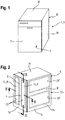
- FIG. 1 a dishwashing machine 1 with a washing container 3 is shown schematically slightly in perspective in front view, in which a washing compartment 5 bounded by the washing container 3 and by a door 11 is present.
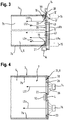
- FIG. 2 shows the rinse tank 3 slightly perspective view from its rear side.
- a dishwasher is often designed as a built-in device, and is then surrounded in the installed state on the outside of furniture walls, with an outer housing can be partially or completely eliminated. Otherwise, it can expediently have a housing 13 formed by outer walls 13, which surrounds the washing container 3.
- the washing compartment 3 here has a front loading opening 6 closable by a front door 11 and a total of five walls 7, namely a ceiling wall 7a, two side walls 7b, a bottom wall 7c and a rear wall 7d, at least one of these walls, in particular the rear wall 7d, which is referred to by way of example below, is replaced by two light-emitting surface elements 8 to at least 20%.
- the luminous surface elements each cover one of two openings 23 present in the rear wall 7d (in FIG Fig. 2 shown with dashed lines), wherein the openings of a stiffening web 9 are separated from each other.
- the luminous surface elements 8 preferably replace at least 50%, in particular at least 75%, preferably between 80% and 95%, of the surface of at least one wall, in particular of the rear wall 7d.
- a surface replacement of 95% takes the stiffening web 9 at least a portion of the remaining remaining area of 5%.
- Each luminous surface element 8 thus forms a large-area illumination unit or light design unit, which bright the respective replaced wall surface towards the other walls such as 7a, 7b, 7c shine.
- it may in particular be designed as a backlight, preferably uniformly radiating, or as a diffuse luminous emitter.
- it is designed as a planar surface plate, plane-surface panel or plane-surface film, so that it is good for replacing a wall or a wall part. In this case, it preferably has a rectangular shape (viewed in plan view).
- the stiffening web 9 extending in the vertical or vertical direction also runs centrally between the two apertures covered or closed by luminous surface elements.
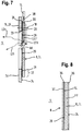
- the stiffening web increases the stability of the washing container. But it also serves as a mounting bar, can be mounted on the components, for example, a fixed in the washing chamber 5 on the rear wall 7d and vertically extending feed line 12 for supplying washing liquid to a spray arm ( Figure 4 ).
- the outer side 4 of the stiffening web 9 facing away from the flushing space 5 can likewise be used to assemble components, for example hoses or lines (not shown), which likewise serve to supply flushing fluid to a spray arm.
- a side wall 7b is in Fig. 2 a further situation indicated, in addition to or independent of the above-explained vertical arrangement of the two openings 23 in the rear wall 7d with the existing between them vertical stiffening web 9 of the stiffening web 9 'and the openings 23' in the depth direction of the washing container 3 and horizontally.
- the stiffening web can be used in this case to fix on its inside guide means, in particular guide slots for a movable in the depth direction receiving basket (not shown).
- a luminous surface element can shine or emit light
- it is expediently designed as a light-conducting or light-guiding light guide.
- light rays that are in the luminous surface element for example, from a light source arranged outside the washing, such as 14 (see, eg FIG. 3, 4 ) coupled be produced in the material of the luminous element by energetic excitation, in this propagating and at a plurality of decoupling points, in particular transversely to their direction of propagation, from the interior of the rinsing container facing inner wall of the luminous surface element are coupled into the interior of the washing.
- the luminous surface element 8 has a flat support plate made of a light-conducting or light-guiding material such as glass, transparent or translucent plastic such as acrylic or a composite of the two materials. It comprises extractors for coupling out light from the light-guiding or photoconductive carrier plate.
- the light decoupling can be achieved by means of reflecting and / or scattering structures distributed in the optical waveguide material of the flat carrier plate, for example FP (see, for example, FIG. 8 ), by targeted, fine surface structures on the washing compartment facing inner wall surface of the light-guiding or photoconductive support plate, and / or by fine, on the washing compartment facing inner wall surface of the light-guiding or photoconductive support plate applied, in particular printed, patterns such as color particles can be realized.
- the inhomogeneous or heterogeneous distribution of the coupling-out structures causes a substantially uniform illumination of the surface of the luminous surface element is achieved, since light rays from the photoconductive or light-guiding support plate is scattered scattered in all directions in the interior of the washing compartment.
- the light-emitting element is designed as a light guide such that light, the z. B. is emitted by one or more point or rod-shaped light sources, which is preferably arranged outside the washing compartment or are distributed as evenly as possible over the surface of the light-emitting element in order to provide a backlight, ie a "backlight" can.
- This is referred to in particular as a light guide or light pipe.
- light such as 38, for example, at an end face such as 39 of the light-emitting element such as 8 are fed (see FIG. 3 ).
- light in the light-guiding material of the luminous surface element 8 on the rear side, ie facing away from the washing compartment 5 outer wall surface such.
- the flat, designed as a light guide plate luminous surface element 8 is preferably made of glass or of a transparent or translucent plastic such as acrylic glass. This contains eg Extractors that decouple the light from the light guide into the washing compartment 5.
- the decoupling can be realized by scattering and / or reflecting structures distributed in the optical waveguide material, by specific fine surface structures, and / or by fine, in particular imprinted patterns, for example in the form of a color layer or another scattering and / or reflection layer.
- light from one or more light sources can advantageously be coupled in at several points of the luminous surface element, such as at several end faces, in particular at two, three or all four end faces of the approximately rectangular plate of the luminous surface element. Additionally or independently thereof, light can also be fed to the light-conducting or light-conducting material of the luminous surface element at the rear outer wall surface of the luminous surface element at a plurality of locations distributed over the outer wall surface.
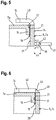
- the luminous surface element 8 is preferably designed to be light-conducting and / or light-emitting such that one or more light beams 38, 45 (see FIG Figures 3 . 7 . 5 ) at least one arranged outside the washing compartment 5 light source 14, 40 in the luminous element 8 at at least one Einkoppelstelle 39, 24 are coupled, one or more coupled light beams such as LS1 '(see FIG. 7 ) in the luminous element 8, starting from their respective Einkoppelstelle 39, 24 away with a parallel to the washing compartment 5 facing inner wall surface 29 of the luminous element 8 extending propagation direction EFR (see FIG.
- the luminous surface element 8 viewed from the washing compartment 5 is formed largely opaque.
- the respective luminous surface element 8 viewed from the dishwashing space side is milky or otherwise diffusely luminous.
- the other walls such as e.g. 7a, 7b, 7c of a washing container as conventionally made of an opaque material, such as e.g. Made of metal and / or opaque plastic.
- a planar illuminating element or a luminous surface element such as e.g. those which are designed as light boxes.
- the light sources are located in a shallow trough, which diffusely reflects the light in its interior and allows it to escape only towards the open side, ie here in the direction of the washing compartment 5.
- specially shaped reflectors are used for fluorescent lamps as light sources and diffuser lenses for LEDs, so that the light emerging from the light trough is approximately homogeneous despite a small overall depth of the backlight.
- the light distributed by the flat plate-shaped optical waveguide or the light trough may still have a spatial structure, it may possibly be advantageous if it is distributed uniformly by means of at least one diffuser so that it comes close to an absolutely uniform, in particular white, luminous surface.
- a simple solution is, for example, an opal scattering plate between the light guide or light trough and the washing compartment 5 facing inner wall surface 29 of the luminous element 8.
- films can be used that homogenize the light more efficient than is possible, for example, with opal glass.
- At least one light source 14 such as a light bulb or light emitting diode in the luminous element 8
- light is forwarded within this and finally emitted into the interior of the washing compartment 3.
- a luminous surface element 8 is fixed with its outer edge region 15, for example, to the other, adjacent, for example made of sheet metal walls 7a - 7c, for which there are a number of different possibilities.
- a luminous surface element 8 is fixed to a fixing flange 16, which delimits an opening 23 in a wall 7 of the washing container 3.
- the luminous surface element 8 is fixed to a mounting surface 17 of the Fixierflansches 16, which is formed either from the inside or from the outside of the Fixierflansches 16.
- the clear width the preferably rectangular opening 23 is viewed in the height direction only slightly smaller than the distance between the bottom wall 7c and ceiling wall 7a and viewed in the width direction only slightly smaller than half the distance between the two side walls 7b.
- the fixing flange 16 can be formed by a 90 ° flanging inwards to the respective opening 23 in the rear wall 7c towards the rear end-side edge regions of the cover wall 7a, the side walls 7b and the bottom wall 7c. However, the fixing flange 16 can also be the remainder of a wall 7, which remains standing after the production of a breakthrough 23 by means of a punching.
- the fixation of the large-area luminous surface element 8 on the fixing flange 16 can take place, for example, with the aid of an adhesive layer 21, which also ensures a sealing of an existing between the mounting surface 17 and the luminous surface element 8 parting line 19, so that no rinsing liquid between the Fixierflansch 16 and the luminous element 8 after can step outside.
- an adhesive layer 21 which also ensures a sealing of an existing between the mounting surface 17 and the luminous surface element 8 parting line 19, so that no rinsing liquid between the Fixierflansch 16 and the luminous element 8 after can step outside.
- FIG. 9 an additional or alternative fixation is shown, namely via a screw connection between the outer edge region 15 of the plate-shaped, in particular rectangular luminous surface element 8 and the fixing flange 16.
- the screw is in Fig. 9 indicated by a dashed line 18.
- a seal 20 is arranged for example of an elastomeric material.
- the luminous sheet may be attached to the inside or as shown in FIG Fig.
- the luminous surface element 9 is dimensioned so that it surrounds the opening 23 framing edge 25 of the wall 7d and the Fixierflansch 16 on the outside, that overlaps on the side facing away from the washing compartment 5.
- the fixation of the luminous surface element 8 on the fixing flange 16 of the rear wall 7d can in turn be done in different ways, for example by means of an adhesive layer 28, which also performs a seal in the overlap region 27 between the edge 25 and the luminous element 8 existing parting line 26.
- the fixation can continue additionally or alternatively by a screw, indicated by the dot-dash line 18, take place.
- an adhesive layer 28 can also be a circumferential seal, corresponding to the seal 20 in Fig. 9 , be provided.
- the respective luminous surface element 8 can in particular be designed such that the light emitted by it into the flushing chamber has a different color than the coupled-in light of the light source 14. This can be made possible, for example, by the fact that the material of the luminous surface element 8 dyes FP or other litter Contains - and / or reflection particles. It is also conceivable that, in addition or as an alternative, a color layer 36 or other particle layer, for example in the form of a colored plastic film or the like. attached to the inside or inside wall surface 29 and / or the outside or outside wall surface 24 of the luminous surface element 8, 9, is glued approximately ( Fig. 8 ).
- luminescent dyes can also be used as dyes. Another embodiment is to form the wanderabilityde luminous surface element 8 as a light guide, in particular, together with a luminescent dye contained in the material of the luminous element 8 further optical design options arise.
- the light-emitting surface element 8 can be located on the inside, i. on the side facing the washing compartment 5 with a protective layer 37 of a from the inside of the luminescent surface element 8, 9 outwardly towards the washing compartment 5 translucent material, for example, be provided with a paint or a plastic film that from the outside, in particular from the washing compartment 5 forth largely opaque, especially opaque.
- the protective layer 37 is braded either directly on the inner wall of the light-conducting carrier plate of the luminous surface element facing the washing compartment. If a color layer 36 is present on the interior wall surface 29 facing the dishwashing space, the protective layer is applied thereon as the topmost finishing layer, as shown in FIG Fig. 8 is shown.
- the emission of light into the washing compartment 5 can be enhanced by providing the luminous surface element 8 on the outside, ie on the outer wall surface 24 facing away from the washing compartment 5, with a layer reflecting light rays toward the washing compartment 5.
- the coupling of light can in principle be such that the light source 14 at a distance, that is, while leaving an air gap to the luminous element 8 is arranged.
- the light source 14 can then be configured in particular such that its light cone 38 completely loads the outer wall surface 24 of the luminous surface element 8.
- a plurality of light sources 14 may be provided offset from one another in such a way that their light cones cover different areas of the outer wall surface 24 of a luminous surface element 8 or, as shown in FIG Fig. 4 the case is, in each case a luminous surface element 8 is associated with at least one light source.
- an arrangement of a light source 14 is also conceivable such that its light cone 38 acts on the end face 39 of the light-emitting surface element 8 ( Fig. 3 ). Possibly. can also be provided on several end faces of the luminous element 8, one or more light sources for the frontal coupling of light.
- an optical transmission element 40 may be provided for coupling in the light. This is formed, for example, from one or more optical waveguides, for example glass fibers, and is coupled on the one hand to the light source 14 and on the other hand to an outer wall surface 24 or an end face 39 of the luminous surface element 8.
- the optical coupling between the transmission element 40 and the light-emitting surface element 8 can take place without contact, in particular with the interposition of an optical or imaging unit.
- a distance 44 or a free air gap is then present.
- a light cone 45 is formed (see Fig. 5 ).
- the optical coupling can also be direct, ie the light exit surface 43 of the transmission element 40 is in mechanical connection with the light-emitting surface element 8.
- the light exit surface 43 may be preceded by an optical deflection element 46 or an optical imaging system.
- Fig. 3 a case is shown in which a plurality of transmission elements 40a, 40b are optically coupled to a light source 14, the light exit surfaces 43 are arranged at different positions of the outer wall surface 24 of the luminous element 8.
- Fig. 10 shows as a detail the rear wall 7d of a washing container 3. This is preferably integral with the example deep-drawn washing container 3 (in Fig. 10 not shown).
- two window-like apertures 23 are present, which are substantially rectangular and extend substantially vertically over almost the entire height of the washing container 3 or the rear wall 7d.
- the preferably produced by a punching process openings 23 are bounded by an edge of the rear wall 7d, which forms a Fixierflansch 16 in particular for fixing a luminous element 8.
- the apertures 23 are separated from one another by a stiffening web 9, wherein this, like the apertures 23, also extends in the vertical direction of the washing container 3.
- the reduced due to the replacement of a majority of the rear wall 7d by a luminous region mechanical stability of the washing container 3 is also increased by the fact that the luminous region is realized by two by a stiffening web separate openings 23 or this overlapping or occluding luminous surface elements 8 in that the fixing flange 16 is offset in the transverse direction 58 of the wall relative to the plane 47 which is spanned by the stiffening web.
- the stiffening web 9 is thus seen in cross-section the shape of a C-profile, which in particular significantly increases its buckling and torsional rigidity.
- the openings bounding wall portions are formed due to the offset in question in the manner of angle profiles or stepped, which further increases the mechanical stability of the rear wall.
- the offset of the Fixierflansches 16 can be produced in a simple manner by a recess 48 is impressed from the inside or outside thereof in the rear wall 7 d (or another wall of the washing container) and then a region of the recess 48 corresponding to the opening 23 is punched out.
- the fixing flange 16 is offset towards the washing compartment 5, ie the depression 48 has been pressed from the outside of the rear wall 7d in the direction of the washing compartment.
- a luminous surface element 8 can be attached to the outside of the fixing flange 16 pointing away from the washing compartment 5, with part of its thickness being received by the depression or recess 48, ie the luminous surface element 8 is not or only partly over that of the recess Stiffening bar spanned level 47 addition. This is advantageous if the space at the Spül relierland.
- a luminous surface element 8 can be designed in such a way that, in addition to its lighting function, it fulfills further functions, such as increasing the rigidity and mechanical strength of the respective wall or being resistant to the conditions prevailing in the washing compartment during the cleaning operation.
- the disadvantage here is that such additional functions are often not given in commercially available light-emitting elements, so that special developments are required.
- requirements exceeding the luminous function are preferably realized with the aid of at least one transparent, translucent or reflective surface element FE arranged on one side of the luminous surface element 8 and covering the opening.
- the respective surface element FE is not connected over a large area, for example, in the manner of a lamination with the luminous surface element.
- the luminous surface element and the respective surface element FE associated with it are separated from each other by an air gap 49a, 49b.
- the gap width of the air gap 49a, 49b is greater than 1 ⁇ m. The occurrence of disturbing light-dark zones due to interference phenomena, so-called Newtonian rings, is thereby prevented.
- the air gap 49a, 49b can also be used for thermal insulation. Air present in the air gap 49a, 49b can act as an insulator. If the gap width of the air gap 49a, 49b is limited to a maximum of 2 cm, the formation of air convection, which would reduce the insulating effect of the air cushion in the air gap, can be prevented.
- each luminous surface element 8 is assigned a surface element FE in the form of a front plate 50 and / or on its side facing away from the washing area a reflective surface element FE in the form of a reflector film 53, leaving an air gap 49a, 49b free.
- the gap width of the air gap 49a is 0.5 mm and the gap width of the air gap 49b is 0.1 mm.
- the header plate 50 has a thickness of about 2 mm and is made of a plastic which is resistant to the chemicals used during operation in the washing compartment, for example of PMMA or polyamide.
- the reflector sheet 53 has, as Fig. 14 can be seen, preferably a multilayer structure.
- the base film 52 made of transparent or translucent material, for example of a polyacrylate, whose side facing away from the washing compartment 5 is provided with a reflector film 54 whose reflective property, for example, on a coating with white paint, for example with TiO 2 , or due to a metallization.
- the light is coupled into the luminous surface element 8 via one of its end faces 84.
- the corresponding light source 14, preferably an LED strip 55 positioned on the front side on the luminous surface element 8, is dimensioned or oriented in such a way that the light radiated from it does not reach the front side only the luminous surface element 8, but at the same time via an end face 85 of the reflector film 53 in this, ie mainly in the base film 52, is coupled.
- the side facing the flushing space 5 is provided with at least one diffuser layer 56, that is to say a light-scattering film or pane.
- the above-described effect of a uniform illumination Spülraums 5 is further enhanced in this way.
- the aperture covering surface element FE such as a front plate 50
- the fixing flange 16 are various options into consideration.
- a fixation is preferably such that a relative movement between the luminous surface element 8 and / or the surface element and the fixing flange 16, which is based on different thermal expansions and extends parallel to the plane 62 spanned by the fixing flange 16, is compensated.
- this is accomplished in that the luminous surface element 8 and / or the surface element FE, in particular the above-mentioned header plate 50 with the interposition of an elastic, by the relative movement in question caused shear forces Leveling layer 57 adhesively connected to the fixing flange 16.
- the compensating layer 57 which is preferably configured in the form of an O-ring, may be provided or provided with adhesive, for example an acrylic adhesive, on its side facing the fixing flange 16 and facing away from its fixing flange 16, that is to say in the manner of a double-sided adhesive tape be educated.
- the shear forces absorbing effect of the compensating layer 57 is particularly well pronounced when this is at least partially, preferably completely formed by a plastic foam, in particular a polyolefin foam, since the cellular space structure of the foam allows particularly high absorption of shear forces.
- a certain minimum thickness of the leveling layer of 0.2 mm to 0.4 mm is required.
- the maximum thickness of the compensation layer should expediently not exceed 2 mm, more preferably 1 mm.
- the attachment plate 50 may be made of a relatively stable material so that it can contribute to the stability of a wall 7 at least partially replaced by a lighting element 8.
- a material is selected which is resistant to the chemicals used in the dishwasher during operation of the dishwasher.
- the choice of the luminous surface element 8 itself can then be made exclusively according to optical or lighting-technical aspects, without regard to mechanical or chemical properties or requirements.
- the attachment plate 50 is made with the aid of a connecting element V, which is preferably connected to the carrier T by means of a positive engagement with the wall 7d in the transverse direction 58.
- a connecting element V is particularly advantageous in terms of assembly technology, since it can be configured for example as a snap connection, which only requires a simple linear joining movement during assembly.
- a defined air gap 49a, 49b between the elements in question can be maintained by a form-fitting connection, in particular on assembly technology simple manner.
- a luminous surface element 8 or a surface element FE for example a reflector film 53
- an effective in the transverse direction wall 58 positive connection which is in particular realized by one or more snap connections.
- luminous surface elements 8 and / or surface elements FE can be connected with a simple linear joining movement with the connecting element V, which is already fixed on the support T, for example.
- the connecting element V is preferably a frame 59, which on the one hand the carrier T, so about the attachment plate 50, and on the other hand other planar elements, preferably a luminous surface element 8 and / or one or more surface elements FE, surrounds and said elements together with a force acting in the transverse direction of the wall 58 form fit together.
- the frame 59 engages behind the handle elements 60, the washing compartment 5 facing side 63 of the carrier T and the attachment plate 50.
- the locking elements 60 are tab-shaped wall portions which are parallel to the plane defined by the frame 59 Plane plane or parallel to the spanned by the stiffening web 9 Level 47 extend.
- the thickness of the compensation layer 57 is selected such that a gap 64 remains free between the fixing flange 16 and the carrier T or the attachment plate 50, whose gap width measured in the transverse direction 58 of the wall is greater than the thickness 70 of the engagement elements 60 in that the elastic compensation layer 57 which is elastic in the transverse direction 58 of the wall is compressible to a certain extent during installation for the purpose of a sufficient adhesive bond between the support T and the fixing flange 16 in the transverse direction 58 of the wall, without the frame 59 coming into contact with the fixing flange 16 or the pressing of the Leveling layer 57 impeded to the fixing flange 16.
- the frame 59 has a first receptacle 65, in which the carrier T or the attachment plate 50 is completely received.
- the receptacle is bounded laterally by a wall 66, which extends in the transverse direction of the wall 58 away from the rear grip elements 60.
- the pointing away from the washing compartment 5 free ends of the wall 66 are at least partially formed as a rear grip elements H, which engage behind the carrier T on its side facing away from the washing compartment 5 page 68.
- the rear grip elements H are preferably formed in the form of circumferentially of the frame 59 distributed hook strips 67.
- the frame 59 has a further receptacle 73 which serves for preferably complete reception of the luminous surface element 8.
- the the washing compartment 5 opposite side of the rear grip elements H defines a support plane 74, on which the luminous surface element 8 is applied.
- the frame 59 is essentially formed by a wall 76 having a step 76, wherein the surface of the step 76 facing away from the washing chamber 5 extends in the support plane 74. In the assembled state, therefore, the luminous surface element 8 rests on the catch elements H and on the step 76.
- the dimension of the engagement elements H in the transverse direction 58 of the wall defines the gap width of the gap 49a present between the luminous element 8 and the carrier T or the attachment plate 50.
- a wall portion 77 of the wall 75 extending from the step 76 in the direction of the washing compartment 5 surrounds the wall 66 having the rear grip elements H with a lateral spacing 78.
- the free end of the wall section 77 facing the washing compartment 5 is formed with a wall 81 running parallel to the support plane 74. from which the wall 66 extends toward the receptacle 73 away.
- Free ends of the stepped wall 75 are grasping elements H'angeformt which engage behind the flushing chamber 5 side 79 of the luminous surface element 8 at least indirectly.
- the rear grip elements H ' which are preferably designed as hook strips 80 distributed in the circumferential direction of the frame 59, act directly on the side 61 of the luminous surface element facing away from the washing compartment 5.
- a surface element FE in particular the above-mentioned reflector film 53 is arranged.
- the air gap 49b is defined by marginal spacers (not shown). The rear grip elements H 'engage behind the reflector film 53, thus lie against this.
- the hook strips 80 are also formed on their side facing away from the washing compartment 5 with a run-on bevel 71 facilitating the introduction of the optionally provided with a reflector sheet 53 luminous surface element 8 in the joining direction 72.
- the catch elements H' may act like snap-in connection elements or are designed as such.
- the light-emitting surface element 8 is assigned a light source 14 in the form of an LED strip 55, this being arranged in a receptacle 83 which opens to the flushing space 5.
- the light source 14 or the LED strip 55 is dimensioned and arranged such that light emanating from it is directed both into the end face 84 facing it of the luminous surface element 8 as well as in its facing end 85 of the reflector sheet 53 is coupled, which is indicated by the arrows 86 in Fig. 12 is indicated.
- FIG. 15 schematically shows a perspective view of another advantageous embodiment of an illuminated wall, which limits the washing compartment, in particular the rear wall of the washing container of the dishwasher of FIG. 1 and viewed from the outside, wherein additionally exemplified the individual components of a single illumination field of the wall are shown in an exploded view.
- the rear wall 7d two vertical rows of three superposed openings 23 are provided side by side, ie a total of 6 openings in the rear wall 7d are present.
- the respective opening 23 is rectangular.
- vertical and horizontal stiffening webs of the preferably metallic wall 7d have stopped, so that their rigidity is sufficiently ensured despite the openings.
- the illumination element IL comprises, as seen from the interior of the washing compartment 5, the flushing-resistant cover plate 50 which is on the rear side, ie the outside of the wall 7d, by means of a frame-shaped adhesive mask 572 glued.
- the adhesive mask rests on a fixing flange 16 of the wall 7d extending around the aperture 23. This is preferably formed trough-shaped recessed towards the washing compartment and takes the attachment plate 50, in particular largely flush, on.
- the intent plate 50 is thus fixed by means of the adhesive mask 572 on the opening 23 encircling edge of the wall 7d.
- the adhesive mask 572 at the same time forms a liquid-tight seal between the attachment plate 50 and the edge zone 16 of the rear wall 7d around the aperture 23.
- it serves as a compensation layer for receiving shear forces, which may occur through different thermal expansions of the rear wall 7d and the attachment plate 50.
- Such different thermal expansions may be due to different materials for the rear wall 7d such as steel and the header plate 50 such as plastic, as they have different thermal expansion coefficients.
- the illumination element IL has behind the front plate 50 (viewed from inside to outside) the light-emitting element or light panel 8.
- the luminous surface element 8 is mounted on the front side in a cover frame serving as a holding element HE.
- the holding element HE has a closed rear wall RE, which is designed as a reflector surface element.
- the rear wall of the holding element HE on its side facing the light panel 8 may be provided with a white color layer or a white coating as a light-reflecting background.
- the cover frame HE also takes at the same time a light strip such.
- LED strip LL or other elongated light source such that light can be coupled along the longitudinal extension of an end face in this, in particular in the upper end side of the here in the embodiment rectangular light panel 8.
- the light panel 8 is expediently supported in the cover frame HE in such a way that an air gap of predetermined gap width is present between it and the light-reflecting rear wall RE, in order to prevent unwanted luminous phenomena, such as, for example, To avoid Newton's rings and to ensure a largely homogeneous, with respect to the total area of the light panel 8, uniform illumination. At each local point of the light panel 8, this therefore preferably illuminates approximately with the same luminosity.
- the cover frame HE with the light panel 8 held by it advantageously by means of a mechanical attachment to the outside of the rear wall 7d viewed from the inside out behind the attachment plate 50, which covers the opening 23 by means of the adhesive mask 572 liquid-tight or closes, with a predetermined gap distance staggered.
- the washing compartment 5 facing side of the rear wall 7d provided a preferably rectangular frame BR, which is fixed by means of a here rectangular adhesive mask 571 on the wall edge all around the here rectangular opening 23 flushing chamber side.
- the frame BR has on its rear side a plurality of pins, pins or bolts SI, which are passed through corresponding holes or holes BO in the rear wall 7d, the header plate 50, in the cover frame HE and in an optionally additionally present contact frame APR and by means of lock washers SS are counterclaimed on the outside of the cover HE.
- the cover frame HE with the content in it held light panel 8 is thus behind in a given free space distance the attachment plate 50 fixed by a mechanical attachment to the outside of the rear wall 7d.
- the flushing space provided on the inside can be omitted BR frame and provided for fixing adhesive mask 571.
- the mechanical fixation of components such as e.g. 50, HE of the illumination element IL can then take place in a corresponding manner as explained above by means of a counter-holder.
- the illumination element IL By the combination of adhesive bonding and additional mechanical attachment of the illumination element IL to the illumination wall, e.g. 7d, the overall construction of which is largely liquid-tight and largely insensitive to shocks from outside and inside.
- the mechanical attachment of the illumination element on the wall provides relief of the sealing adhesive connection between the attachment plate 50 and the support zone, in particular the fixing flange 16, which surrounds the respective opening 23.
- the cover frame HE can be designed in particular such that it is arranged in a defined free space distance in front of the light panel 8, i. before the washing room facing side, and the lye-stable attachment plate 50 receives and holds.
- the adhesive connection 572 is provided between the washing compartment facing outer edge of the attachment plate 50 and the support zone 16 and the illumination element IL additionally fixed to the outside of the wall by means of a suitable mechanical attachment.
- This overall structure of the illumination element IL which according to an advantageous embodiment variant (viewed from the inside outwards) comprises the cover frame HE, the attachment plate 50, the light panel 8 behind it with predetermined gap spacing, and the reflector surface element RE behind this with predetermined gap distance, can, if necessary, according to an advantageous alternative ., Only by means of the adhesive mask 572 on which the breakthrough 23 enclosing all around, rear fixing edge, in particular Fixierflansch 16 of the rear wall 7 d of the washing container to be fixed. An additional mechanical attachment is therefore missing in this variant.
- the respective wall provided for the illumination which delimits the dishwashing space becoming wet in the dishwashing mode, has a multiplicity of illumination elements which cover or close the associated apertures in the wall.
- the openings remain separated by remaining webs of wall material such as steel sheet.
Landscapes
- Physics & Mathematics (AREA)
- General Physics & Mathematics (AREA)
- Optics & Photonics (AREA)
- Engineering & Computer Science (AREA)
- General Engineering & Computer Science (AREA)
- Washing And Drying Of Tableware (AREA)
- Electroluminescent Light Sources (AREA)
Priority Applications (1)
| Application Number | Priority Date | Filing Date | Title |
|---|---|---|---|
| PL14716349T PL2986197T3 (pl) | 2013-04-16 | 2014-04-10 | Zmywarka do naczyń z co najmniej dwoma świecącymi elementami powierzchniowymi |
Applications Claiming Priority (2)
| Application Number | Priority Date | Filing Date | Title |
|---|---|---|---|
| DE201310206865 DE102013206865A1 (de) | 2013-04-16 | 2013-04-16 | Geschirrspülmaschine mit zwei Leuchtflächenelementen in wenigstens einer Wand ihres Spülbehälters |
| PCT/EP2014/057271 WO2014170202A1 (de) | 2013-04-16 | 2014-04-10 | Geschirrspülmaschine mit zumindest zwei leuchtflächenelementen |
Publications (2)
| Publication Number | Publication Date |
|---|---|
| EP2986197A1 EP2986197A1 (de) | 2016-02-24 |
| EP2986197B1 true EP2986197B1 (de) | 2018-02-21 |
Family
ID=50473324
Family Applications (1)
| Application Number | Title | Priority Date | Filing Date |
|---|---|---|---|
| EP14716349.7A Active EP2986197B1 (de) | 2013-04-16 | 2014-04-10 | Geschirrspülmaschine mit zumindest zwei leuchtflächenelementen |
Country Status (6)
| Country | Link |
|---|---|
| US (1) | US10045679B2 (pl) |
| EP (1) | EP2986197B1 (pl) |
| CN (1) | CN105120729A (pl) |
| DE (1) | DE102013206865A1 (pl) |
| PL (1) | PL2986197T3 (pl) |
| WO (1) | WO2014170202A1 (pl) |
Families Citing this family (10)
| Publication number | Priority date | Publication date | Assignee | Title |
|---|---|---|---|---|
| DE102011084458A1 (de) | 2011-10-13 | 2013-04-18 | BSH Bosch und Siemens Hausgeräte GmbH | Haushaltsgerät mit mindestens einem Leuchtflächenelement im Behandlungsraum |
| DE102013206869A1 (de) | 2013-04-16 | 2014-11-06 | BSH Bosch und Siemens Hausgeräte GmbH | Geschirrspülmaschine mit wenigstens einem von einem Leuchtflächenelement und diesem beigeordneten Flächenelement überdeckten Durchbruch in mindestens einer Wand ihres Spülbehälters |
| DE102013208374B4 (de) * | 2013-05-07 | 2016-08-18 | Meiko Maschinenbau Gmbh & Co. Kg | Reinigungsvorrichtung mit beleuchtetem Türgriff |
| US9538900B2 (en) * | 2013-12-19 | 2017-01-10 | Whirlpool Corporation | Door assembly for a dishwasher |
| DE102015206298B3 (de) * | 2015-04-09 | 2016-08-11 | BSH Hausgeräte GmbH | Wäschepflegegerät mit einem Beleuchtungselement |
| DE102016204507A1 (de) * | 2016-03-18 | 2017-09-21 | BSH Hausgeräte GmbH | Geschirrspülmaschine mit einer Innenbeleuchtung |
| CN114060738B (zh) * | 2021-10-08 | 2024-07-19 | 国网河北省电力有限公司大名县供电分公司 | 一种电力工程用照明装置 |
| CN115195145B (zh) * | 2022-09-14 | 2023-02-10 | 浙江嘀视科技有限公司 | 一种车灯灯壳与灯罩的压合装置 |
| EP4732738A4 (en) * | 2023-07-28 | 2026-04-29 | Lg Electronics Inc | DISHWASHER |
| WO2025028940A1 (ko) * | 2023-07-28 | 2025-02-06 | 엘지전자 주식회사 | 식기세척기 |
Citations (1)
| Publication number | Priority date | Publication date | Assignee | Title |
|---|---|---|---|---|
| US20040042196A1 (en) * | 2002-02-02 | 2004-03-04 | Edward Robert Kraft | Flat panel luminaire having embedded light guides |
Family Cites Families (32)
| Publication number | Priority date | Publication date | Assignee | Title |
|---|---|---|---|---|
| DE1051234B (de) | 1955-02-28 | 1959-02-26 | Siemens Elektrogeraete Gmbh | Trommelwaschmaschine |
| US3571939A (en) | 1969-09-04 | 1971-03-23 | Beverly Paul | Dish drying and sterilizing arrangement |
| US3915180A (en) | 1973-11-30 | 1975-10-28 | Gen Motors Corp | Dishwasher with energy radiating heat lamps |
| US5836669A (en) * | 1996-01-17 | 1998-11-17 | Troy Investments, Inc. | Remote illumination and light apportionment in appliances |
| US5979472A (en) | 1998-04-29 | 1999-11-09 | Lowery; Ginger E. | Toy washer and disinfector device |
| JPH11346976A (ja) | 1998-06-09 | 1999-12-21 | Mitsubishi Electric Corp | 食器洗浄乾燥機 |
| US6059420A (en) | 1999-02-17 | 2000-05-09 | Rogers; Thomas | See through refrigerator door construction |
| DE10065641A1 (de) | 2000-12-29 | 2002-07-04 | Bsh Bosch Siemens Hausgeraete | Spülbehälter für eine Geschirrspülmaschine |
| BR0213489A (pt) | 2001-10-25 | 2004-11-03 | Bsh Bosch Siemens Hausgeraete | Dispositivo de iluminação para fornos |
| ITTO20011191A1 (it) | 2001-12-18 | 2003-06-18 | Itw Ind Components Srl | Dispositivo di servizio per un frigorifero e frigorifero provvisto ditale dispositivo. |
| DE10210842A1 (de) * | 2002-03-12 | 2003-09-25 | Electrolux Home Prod Corp | Vorrichtung und Verfahren zur Erfassung des Trockengrades in einem Haushaltsgerät |
| US7483092B2 (en) | 2002-07-11 | 2009-01-27 | Diehl Ako Stiftung & Co. Kg | Back-lit liquid crystal display, in particular for use as a display module behind the operating panel of a large domestic appliance |
| DE20210707U1 (de) | 2002-07-11 | 2003-11-20 | Diehl AKO Stiftung & Co. KG, 88239 Wangen | Hinterleuchtete Flüssigkristallanzeige, insbesondere zum Einsatz als Anzeigemodul hinter der Bedienblende eines Haushaltsgroßgerätes |
| DE10318859A1 (de) | 2003-04-25 | 2004-11-11 | BSH Bosch und Siemens Hausgeräte GmbH | Gargerät |
| DE10337327A1 (de) | 2003-08-12 | 2005-03-17 | Koch Gmbh & Co. Kg | Bedienfeld und Haushaltsgerät |
| DE10339904A1 (de) * | 2003-08-29 | 2005-03-17 | BSH Bosch und Siemens Hausgeräte GmbH | Kältegerät mit OLED-Innenbeleuchtung |
| EP1624101A1 (de) | 2004-08-05 | 2006-02-08 | Electrolux Home Products Corporation N.V. | Blendeneinheit für ein elektrisch betriebenes Haushaltsgerät sowie Haushaltsgerät mit einer solchen Blendeneinheit |
| DE102005047915A1 (de) | 2005-10-06 | 2007-04-12 | BSH Bosch und Siemens Hausgeräte GmbH | Haushaltsgerät, insbesondere Einbau-Haushaltsgerät mit einer steuerbaren Betriebsanzeige |
| AU2006300138B2 (en) | 2005-10-13 | 2010-07-15 | Lg Electronics Inc. | Washing machine having UV generator |
| DE102005057154A1 (de) * | 2005-11-30 | 2007-05-31 | BSH Bosch und Siemens Hausgeräte GmbH | Haushaltsgerät mit einem von einer Glastür her beleuchteten Innenraum |
| DE102005062478A1 (de) | 2005-12-27 | 2007-07-05 | BSH Bosch und Siemens Hausgeräte GmbH | Geschirrspülmaschine mit einer Behälterhaube aus preiswertem Stahl |
| CN101198233A (zh) | 2006-12-08 | 2008-06-11 | 奥斯兰姆奥普托半导体有限责任公司 | 电器 |
| DE102007017273A1 (de) | 2007-04-12 | 2008-10-30 | BSH Bosch und Siemens Hausgeräte GmbH | Flachbandkabelbeleuchtung für ein wasserführendes Haushaltsgerät |
| DE102007021298A1 (de) | 2007-05-07 | 2008-11-13 | BSH Bosch und Siemens Hausgeräte GmbH | Haushaltsgerät |
| US8207711B2 (en) | 2008-08-15 | 2012-06-26 | Analog Modules, Inc. | Biphase laser diode driver and method |
| US8047683B2 (en) * | 2009-02-27 | 2011-11-01 | Electrolux Home Products, Inc. | Lighting device mounting system for household appliance, and associated apparatus and method |
| DE102009026712A1 (de) | 2009-06-04 | 2010-12-09 | BSH Bosch und Siemens Hausgeräte GmbH | Hausgerät mit einer Oberfläche, welche einen Photokatalysator aufweist |
| CA2724487A1 (en) * | 2009-12-08 | 2011-06-08 | Magna International Inc. | Appliance doors having integrated lighting and controls |
| DE102011122897B4 (de) * | 2011-07-06 | 2025-11-13 | BSH Hausgeräte GmbH | Geschirrspülmaschine mit wenigstens einem am Spülbehälter beweglich gelagerten Bauteil wenigstens aufweisend einen Lichtleiter |
| DE102011084458A1 (de) | 2011-10-13 | 2013-04-18 | BSH Bosch und Siemens Hausgeräte GmbH | Haushaltsgerät mit mindestens einem Leuchtflächenelement im Behandlungsraum |
| DE102011084459B3 (de) * | 2011-10-13 | 2013-03-28 | BSH Bosch und Siemens Hausgeräte GmbH | Geschirrspülmaschine mit mindestens einem Leuchtelement an mindestens einer Beladeeinheit |
| DE102013206869A1 (de) | 2013-04-16 | 2014-11-06 | BSH Bosch und Siemens Hausgeräte GmbH | Geschirrspülmaschine mit wenigstens einem von einem Leuchtflächenelement und diesem beigeordneten Flächenelement überdeckten Durchbruch in mindestens einer Wand ihres Spülbehälters |
-
2013
- 2013-04-16 DE DE201310206865 patent/DE102013206865A1/de not_active Ceased
-
2014
- 2014-04-10 CN CN201480021616.5A patent/CN105120729A/zh active Pending
- 2014-04-10 US US14/783,089 patent/US10045679B2/en active Active
- 2014-04-10 WO PCT/EP2014/057271 patent/WO2014170202A1/de not_active Ceased
- 2014-04-10 PL PL14716349T patent/PL2986197T3/pl unknown
- 2014-04-10 EP EP14716349.7A patent/EP2986197B1/de active Active
Patent Citations (1)
| Publication number | Priority date | Publication date | Assignee | Title |
|---|---|---|---|---|
| US20040042196A1 (en) * | 2002-02-02 | 2004-03-04 | Edward Robert Kraft | Flat panel luminaire having embedded light guides |
Also Published As
| Publication number | Publication date |
|---|---|
| CN105120729A (zh) | 2015-12-02 |
| WO2014170202A1 (de) | 2014-10-23 |
| EP2986197A1 (de) | 2016-02-24 |
| PL2986197T3 (pl) | 2018-07-31 |
| DE102013206865A1 (de) | 2014-10-16 |
| US10045679B2 (en) | 2018-08-14 |
| US20160045095A1 (en) | 2016-02-18 |
Similar Documents
| Publication | Publication Date | Title |
|---|---|---|
| EP2986198B1 (de) | Geschirrspülmaschine | |
| WO2014170202A1 (de) | Geschirrspülmaschine mit zumindest zwei leuchtflächenelementen | |
| WO2013053829A1 (de) | Haushaltsgerät mit mindestens einem leuchtflächenelement im behandlungsraum | |
| EP2543307B1 (de) | Geschirrspülmaschine, insbesondere haushaltsgeschirrspülmaschine, mit mindestens einem lichtabstrahlenden passivleuchtmittel im innenraum | |
| DE102011080078A1 (de) | Haushaltsgerätetür mit Beleuchtungseinrichtung | |
| EP2602553B1 (de) | Haushaltsgerätetür mit Beleuchtungseinrichtung | |
| DE102011080073B4 (de) | Haushaltsgerätetür mit Beleuchtungseinrichtung | |
| DE102012109030A1 (de) | Beleuchtbares Plattenelement mit einer frontseitigen lichtdurchlässigen Dekorschicht | |
| DE102011088087A1 (de) | Beleuchtungsvorrichtung für ein Gargerät und Gargerät | |
| DE102008034376A1 (de) | Signalleuchte für Fahrzeuge | |
| DE102016204507A1 (de) | Geschirrspülmaschine mit einer Innenbeleuchtung | |
| DE102013206866A1 (de) | Geschirrspülmaschine mit wenigstens einem Leuchtflächenelement und zugeordnetem Wärmedehnungsausgleich | |
| DE102011080072B4 (de) | Haushaltsgerätetür mit Beleuchtungseinrichtung | |
| EP1359371B1 (de) | Leuchte mit Diffusor-Korb | |
| DE102011080071B4 (de) | Haushaltsgerätetür mit Beleuchtungseinrichtung | |
| DE102020201645A1 (de) | Beleuchtungsvorrichtung für ein Kraftfahrzeug | |
| DE202014103896U1 (de) | Spiegelschranktür und Spiegelschrank mit einer solchen Tür | |
| DE102013205824A1 (de) | Beleuchtungsvorrichtung für einen Innenraum eines Haushaltsgeräts sowie Haushaltsgerät mit einer derartigen Beleuchtungsvorrichtung | |
| EP3599965B1 (de) | Geschirrspülmaschine mit zumindest einer wasserzuführung | |
| DE10056966C2 (de) | Abdecksscheibe für eine Leuchte und zugehörige Leuchte | |
| DE202024102888U1 (de) | Leuchte mit einem Lichtleiter und einer Leuchtdiodenanordnung sowie Möbelelement damit | |
| DE202007013177U1 (de) | Leuchte | |
| DE102016101794A1 (de) | Tür zum Öffnen und Schließen eines Innenraums eines Haushaltsgeräts, Haushaltsgerät und Herstellungsverfahren zum Herstellen eines Haushaltsgeräts mit Programmablaufanzeige | |
| DE202013104168U1 (de) | Kofferraumleuchte | |
| EP2792290A2 (de) | Geschirrspülmaschine mit einem innenseitig ein oder mehrere Flächenelemente aufweisenden Spülbehälter |
Legal Events
| Date | Code | Title | Description |
|---|---|---|---|
| PUAI | Public reference made under article 153(3) epc to a published international application that has entered the european phase |
Free format text: ORIGINAL CODE: 0009012 |
|
| 17P | Request for examination filed |
Effective date: 20151116 |
|
| AK | Designated contracting states |
Kind code of ref document: A1 Designated state(s): AL AT BE BG CH CY CZ DE DK EE ES FI FR GB GR HR HU IE IS IT LI LT LU LV MC MK MT NL NO PL PT RO RS SE SI SK SM TR |
|
| AX | Request for extension of the european patent |
Extension state: BA ME |
|
| DAX | Request for extension of the european patent (deleted) | ||
| 17Q | First examination report despatched |
Effective date: 20170117 |
|
| REG | Reference to a national code |
Ref country code: DE Ref legal event code: R079 Ref document number: 502014007324 Country of ref document: DE Free format text: PREVIOUS MAIN CLASS: A47L0015420000 Ipc: F21W0131300000 |
|
| GRAP | Despatch of communication of intention to grant a patent |
Free format text: ORIGINAL CODE: EPIDOSNIGR1 |
|
| RIC1 | Information provided on ipc code assigned before grant |
Ipc: F21V 8/00 20060101ALI20170922BHEP Ipc: A47L 15/42 20060101ALI20170922BHEP Ipc: F21W 131/30 20060101AFI20170922BHEP Ipc: F21V 33/00 20060101ALI20170922BHEP |
|
| INTG | Intention to grant announced |
Effective date: 20171020 |
|
| GRAS | Grant fee paid |
Free format text: ORIGINAL CODE: EPIDOSNIGR3 |
|
| GRAA | (expected) grant |
Free format text: ORIGINAL CODE: 0009210 |
|
| AK | Designated contracting states |
Kind code of ref document: B1 Designated state(s): AL AT BE BG CH CY CZ DE DK EE ES FI FR GB GR HR HU IE IS IT LI LT LU LV MC MK MT NL NO PL PT RO RS SE SI SK SM TR |
|
| REG | Reference to a national code |
Ref country code: GB Ref legal event code: FG4D Free format text: NOT ENGLISH |
|
| REG | Reference to a national code |
Ref country code: CH Ref legal event code: EP |
|
| REG | Reference to a national code |
Ref country code: DE Ref legal event code: R096 Ref document number: 502014007324 Country of ref document: DE Ref country code: AT Ref legal event code: REF Ref document number: 972152 Country of ref document: AT Kind code of ref document: T Effective date: 20180315 |
|
| REG | Reference to a national code |
Ref country code: IE Ref legal event code: FG4D Free format text: LANGUAGE OF EP DOCUMENT: GERMAN |
|
| REG | Reference to a national code |
Ref country code: NL Ref legal event code: MP Effective date: 20180221 |
|
| REG | Reference to a national code |
Ref country code: LT Ref legal event code: MG4D |
|
| PG25 | Lapsed in a contracting state [announced via postgrant information from national office to epo] |
Ref country code: FI Free format text: LAPSE BECAUSE OF FAILURE TO SUBMIT A TRANSLATION OF THE DESCRIPTION OR TO PAY THE FEE WITHIN THE PRESCRIBED TIME-LIMIT Effective date: 20180221 Ref country code: ES Free format text: LAPSE BECAUSE OF FAILURE TO SUBMIT A TRANSLATION OF THE DESCRIPTION OR TO PAY THE FEE WITHIN THE PRESCRIBED TIME-LIMIT Effective date: 20180221 Ref country code: NO Free format text: LAPSE BECAUSE OF FAILURE TO SUBMIT A TRANSLATION OF THE DESCRIPTION OR TO PAY THE FEE WITHIN THE PRESCRIBED TIME-LIMIT Effective date: 20180521 Ref country code: HR Free format text: LAPSE BECAUSE OF FAILURE TO SUBMIT A TRANSLATION OF THE DESCRIPTION OR TO PAY THE FEE WITHIN THE PRESCRIBED TIME-LIMIT Effective date: 20180221 Ref country code: LT Free format text: LAPSE BECAUSE OF FAILURE TO SUBMIT A TRANSLATION OF THE DESCRIPTION OR TO PAY THE FEE WITHIN THE PRESCRIBED TIME-LIMIT Effective date: 20180221 Ref country code: NL Free format text: LAPSE BECAUSE OF FAILURE TO SUBMIT A TRANSLATION OF THE DESCRIPTION OR TO PAY THE FEE WITHIN THE PRESCRIBED TIME-LIMIT Effective date: 20180221 Ref country code: CY Free format text: LAPSE BECAUSE OF FAILURE TO SUBMIT A TRANSLATION OF THE DESCRIPTION OR TO PAY THE FEE WITHIN THE PRESCRIBED TIME-LIMIT Effective date: 20180221 |
|
| PG25 | Lapsed in a contracting state [announced via postgrant information from national office to epo] |
Ref country code: BG Free format text: LAPSE BECAUSE OF FAILURE TO SUBMIT A TRANSLATION OF THE DESCRIPTION OR TO PAY THE FEE WITHIN THE PRESCRIBED TIME-LIMIT Effective date: 20180521 Ref country code: GR Free format text: LAPSE BECAUSE OF FAILURE TO SUBMIT A TRANSLATION OF THE DESCRIPTION OR TO PAY THE FEE WITHIN THE PRESCRIBED TIME-LIMIT Effective date: 20180522 Ref country code: SE Free format text: LAPSE BECAUSE OF FAILURE TO SUBMIT A TRANSLATION OF THE DESCRIPTION OR TO PAY THE FEE WITHIN THE PRESCRIBED TIME-LIMIT Effective date: 20180221 Ref country code: LV Free format text: LAPSE BECAUSE OF FAILURE TO SUBMIT A TRANSLATION OF THE DESCRIPTION OR TO PAY THE FEE WITHIN THE PRESCRIBED TIME-LIMIT Effective date: 20180221 Ref country code: RS Free format text: LAPSE BECAUSE OF FAILURE TO SUBMIT A TRANSLATION OF THE DESCRIPTION OR TO PAY THE FEE WITHIN THE PRESCRIBED TIME-LIMIT Effective date: 20180221 |
|
| PG25 | Lapsed in a contracting state [announced via postgrant information from national office to epo] |
Ref country code: MT Free format text: LAPSE BECAUSE OF FAILURE TO SUBMIT A TRANSLATION OF THE DESCRIPTION OR TO PAY THE FEE WITHIN THE PRESCRIBED TIME-LIMIT Effective date: 20180221 |
|
| PG25 | Lapsed in a contracting state [announced via postgrant information from national office to epo] |
Ref country code: EE Free format text: LAPSE BECAUSE OF FAILURE TO SUBMIT A TRANSLATION OF THE DESCRIPTION OR TO PAY THE FEE WITHIN THE PRESCRIBED TIME-LIMIT Effective date: 20180221 Ref country code: AL Free format text: LAPSE BECAUSE OF FAILURE TO SUBMIT A TRANSLATION OF THE DESCRIPTION OR TO PAY THE FEE WITHIN THE PRESCRIBED TIME-LIMIT Effective date: 20180221 Ref country code: IT Free format text: LAPSE BECAUSE OF FAILURE TO SUBMIT A TRANSLATION OF THE DESCRIPTION OR TO PAY THE FEE WITHIN THE PRESCRIBED TIME-LIMIT Effective date: 20180221 Ref country code: RO Free format text: LAPSE BECAUSE OF FAILURE TO SUBMIT A TRANSLATION OF THE DESCRIPTION OR TO PAY THE FEE WITHIN THE PRESCRIBED TIME-LIMIT Effective date: 20180221 |
|
| REG | Reference to a national code |
Ref country code: DE Ref legal event code: R097 Ref document number: 502014007324 Country of ref document: DE |
|
| PG25 | Lapsed in a contracting state [announced via postgrant information from national office to epo] |
Ref country code: MC Free format text: LAPSE BECAUSE OF FAILURE TO SUBMIT A TRANSLATION OF THE DESCRIPTION OR TO PAY THE FEE WITHIN THE PRESCRIBED TIME-LIMIT Effective date: 20180221 Ref country code: CZ Free format text: LAPSE BECAUSE OF FAILURE TO SUBMIT A TRANSLATION OF THE DESCRIPTION OR TO PAY THE FEE WITHIN THE PRESCRIBED TIME-LIMIT Effective date: 20180221 Ref country code: SM Free format text: LAPSE BECAUSE OF FAILURE TO SUBMIT A TRANSLATION OF THE DESCRIPTION OR TO PAY THE FEE WITHIN THE PRESCRIBED TIME-LIMIT Effective date: 20180221 Ref country code: DK Free format text: LAPSE BECAUSE OF FAILURE TO SUBMIT A TRANSLATION OF THE DESCRIPTION OR TO PAY THE FEE WITHIN THE PRESCRIBED TIME-LIMIT Effective date: 20180221 Ref country code: SK Free format text: LAPSE BECAUSE OF FAILURE TO SUBMIT A TRANSLATION OF THE DESCRIPTION OR TO PAY THE FEE WITHIN THE PRESCRIBED TIME-LIMIT Effective date: 20180221 |
|
| REG | Reference to a national code |
Ref country code: CH Ref legal event code: PL |
|
| REG | Reference to a national code |
Ref country code: BE Ref legal event code: MM Effective date: 20180430 |
|
| PLBE | No opposition filed within time limit |
Free format text: ORIGINAL CODE: 0009261 |
|
| STAA | Information on the status of an ep patent application or granted ep patent |
Free format text: STATUS: NO OPPOSITION FILED WITHIN TIME LIMIT |
|
| REG | Reference to a national code |
Ref country code: IE Ref legal event code: MM4A |
|
| 26N | No opposition filed |
Effective date: 20181122 |
|
| GBPC | Gb: european patent ceased through non-payment of renewal fee |
Effective date: 20180521 |
|
| PG25 | Lapsed in a contracting state [announced via postgrant information from national office to epo] |
Ref country code: LU Free format text: LAPSE BECAUSE OF NON-PAYMENT OF DUE FEES Effective date: 20180410 |
|
| PG25 | Lapsed in a contracting state [announced via postgrant information from national office to epo] |
Ref country code: BE Free format text: LAPSE BECAUSE OF NON-PAYMENT OF DUE FEES Effective date: 20180430 Ref country code: CH Free format text: LAPSE BECAUSE OF NON-PAYMENT OF DUE FEES Effective date: 20180430 Ref country code: LI Free format text: LAPSE BECAUSE OF NON-PAYMENT OF DUE FEES Effective date: 20180430 Ref country code: SI Free format text: LAPSE BECAUSE OF FAILURE TO SUBMIT A TRANSLATION OF THE DESCRIPTION OR TO PAY THE FEE WITHIN THE PRESCRIBED TIME-LIMIT Effective date: 20180221 |
|
| PG25 | Lapsed in a contracting state [announced via postgrant information from national office to epo] |
Ref country code: GB Free format text: LAPSE BECAUSE OF NON-PAYMENT OF DUE FEES Effective date: 20180521 Ref country code: FR Free format text: LAPSE BECAUSE OF NON-PAYMENT OF DUE FEES Effective date: 20180421 Ref country code: IE Free format text: LAPSE BECAUSE OF NON-PAYMENT OF DUE FEES Effective date: 20180410 |
|
| PG25 | Lapsed in a contracting state [announced via postgrant information from national office to epo] |
Ref country code: PT Free format text: LAPSE BECAUSE OF FAILURE TO SUBMIT A TRANSLATION OF THE DESCRIPTION OR TO PAY THE FEE WITHIN THE PRESCRIBED TIME-LIMIT Effective date: 20180221 |
|
| PG25 | Lapsed in a contracting state [announced via postgrant information from national office to epo] |
Ref country code: HU Free format text: LAPSE BECAUSE OF FAILURE TO SUBMIT A TRANSLATION OF THE DESCRIPTION OR TO PAY THE FEE WITHIN THE PRESCRIBED TIME-LIMIT; INVALID AB INITIO Effective date: 20140410 Ref country code: MK Free format text: LAPSE BECAUSE OF NON-PAYMENT OF DUE FEES Effective date: 20180221 |
|
| PG25 | Lapsed in a contracting state [announced via postgrant information from national office to epo] |
Ref country code: IS Free format text: LAPSE BECAUSE OF FAILURE TO SUBMIT A TRANSLATION OF THE DESCRIPTION OR TO PAY THE FEE WITHIN THE PRESCRIBED TIME-LIMIT Effective date: 20180621 |
|
| REG | Reference to a national code |
Ref country code: AT Ref legal event code: MM01 Ref document number: 972152 Country of ref document: AT Kind code of ref document: T Effective date: 20190410 |
|
| PG25 | Lapsed in a contracting state [announced via postgrant information from national office to epo] |
Ref country code: AT Free format text: LAPSE BECAUSE OF NON-PAYMENT OF DUE FEES Effective date: 20190410 |
|
| PGFP | Annual fee paid to national office [announced via postgrant information from national office to epo] |
Ref country code: DE Payment date: 20250430 Year of fee payment: 12 |
|
| PGFP | Annual fee paid to national office [announced via postgrant information from national office to epo] |
Ref country code: TR Payment date: 20250404 Year of fee payment: 12 |
|
| PGFP | Annual fee paid to national office [announced via postgrant information from national office to epo] |
Ref country code: PL Payment date: 20260331 Year of fee payment: 13 |