EP2985751A1 - Anzeigevorrichtung - Google Patents
Anzeigevorrichtung Download PDFInfo
- Publication number
- EP2985751A1 EP2985751A1 EP14783406.3A EP14783406A EP2985751A1 EP 2985751 A1 EP2985751 A1 EP 2985751A1 EP 14783406 A EP14783406 A EP 14783406A EP 2985751 A1 EP2985751 A1 EP 2985751A1
- Authority
- EP
- European Patent Office
- Prior art keywords
- display
- display area
- peripheral edge
- display device
- light
- Prior art date
- Legal status (The legal status is an assumption and is not a legal conclusion. Google has not performed a legal analysis and makes no representation as to the accuracy of the status listed.)
- Granted
Links
Images


Classifications
-
- G—PHYSICS
- G02—OPTICS
- G02F—OPTICAL DEVICES OR ARRANGEMENTS FOR THE CONTROL OF LIGHT BY MODIFICATION OF THE OPTICAL PROPERTIES OF THE MEDIA OF THE ELEMENTS INVOLVED THEREIN; NON-LINEAR OPTICS; FREQUENCY-CHANGING OF LIGHT; OPTICAL LOGIC ELEMENTS; OPTICAL ANALOGUE/DIGITAL CONVERTERS
- G02F1/00—Devices or arrangements for the control of the intensity, colour, phase, polarisation or direction of light arriving from an independent light source, e.g. switching, gating or modulating; Non-linear optics
- G02F1/01—Devices or arrangements for the control of the intensity, colour, phase, polarisation or direction of light arriving from an independent light source, e.g. switching, gating or modulating; Non-linear optics for the control of the intensity, phase, polarisation or colour
- G02F1/13—Devices or arrangements for the control of the intensity, colour, phase, polarisation or direction of light arriving from an independent light source, e.g. switching, gating or modulating; Non-linear optics for the control of the intensity, phase, polarisation or colour based on liquid crystals, e.g. single liquid crystal display cells
- G02F1/133—Constructional arrangements; Operation of liquid crystal cells; Circuit arrangements
- G02F1/1333—Constructional arrangements; Manufacturing methods
- G02F1/133308—Support structures for LCD panels, e.g. frames or bezels
-
- G—PHYSICS
- G01—MEASURING; TESTING
- G01D—MEASURING NOT SPECIALLY ADAPTED FOR A SPECIFIC VARIABLE; ARRANGEMENTS FOR MEASURING TWO OR MORE VARIABLES NOT COVERED IN A SINGLE OTHER SUBCLASS; TARIFF METERING APPARATUS; MEASURING OR TESTING NOT OTHERWISE PROVIDED FOR
- G01D11/00—Component parts of measuring arrangements not specially adapted for a specific variable
- G01D11/28—Structurally-combined illuminating devices
-
- B—PERFORMING OPERATIONS; TRANSPORTING
- B60—VEHICLES IN GENERAL
- B60K—ARRANGEMENT OR MOUNTING OF PROPULSION UNITS OR OF TRANSMISSIONS IN VEHICLES; ARRANGEMENT OR MOUNTING OF PLURAL DIVERSE PRIME-MOVERS IN VEHICLES; AUXILIARY DRIVES FOR VEHICLES; INSTRUMENTATION OR DASHBOARDS FOR VEHICLES; ARRANGEMENTS IN CONNECTION WITH COOLING, AIR INTAKE, GAS EXHAUST OR FUEL SUPPLY OF PROPULSION UNITS IN VEHICLES
- B60K35/00—Instruments specially adapted for vehicles; Arrangement of instruments in or on vehicles
- B60K35/20—Output arrangements, i.e. from vehicle to user, associated with vehicle functions or specially adapted therefor
- B60K35/21—Output arrangements, i.e. from vehicle to user, associated with vehicle functions or specially adapted therefor using visual output, e.g. blinking lights or matrix displays
- B60K35/215—Output arrangements, i.e. from vehicle to user, associated with vehicle functions or specially adapted therefor using visual output, e.g. blinking lights or matrix displays characterised by the combination of multiple visual outputs, e.g. combined instruments with analogue meters and additional displays
-
- B—PERFORMING OPERATIONS; TRANSPORTING
- B60—VEHICLES IN GENERAL
- B60K—ARRANGEMENT OR MOUNTING OF PROPULSION UNITS OR OF TRANSMISSIONS IN VEHICLES; ARRANGEMENT OR MOUNTING OF PLURAL DIVERSE PRIME-MOVERS IN VEHICLES; AUXILIARY DRIVES FOR VEHICLES; INSTRUMENTATION OR DASHBOARDS FOR VEHICLES; ARRANGEMENTS IN CONNECTION WITH COOLING, AIR INTAKE, GAS EXHAUST OR FUEL SUPPLY OF PROPULSION UNITS IN VEHICLES
- B60K35/00—Instruments specially adapted for vehicles; Arrangement of instruments in or on vehicles
- B60K35/20—Output arrangements, i.e. from vehicle to user, associated with vehicle functions or specially adapted therefor
- B60K35/21—Output arrangements, i.e. from vehicle to user, associated with vehicle functions or specially adapted therefor using visual output, e.g. blinking lights or matrix displays
- B60K35/22—Display screens
-
- B—PERFORMING OPERATIONS; TRANSPORTING
- B60—VEHICLES IN GENERAL
- B60K—ARRANGEMENT OR MOUNTING OF PROPULSION UNITS OR OF TRANSMISSIONS IN VEHICLES; ARRANGEMENT OR MOUNTING OF PLURAL DIVERSE PRIME-MOVERS IN VEHICLES; AUXILIARY DRIVES FOR VEHICLES; INSTRUMENTATION OR DASHBOARDS FOR VEHICLES; ARRANGEMENTS IN CONNECTION WITH COOLING, AIR INTAKE, GAS EXHAUST OR FUEL SUPPLY OF PROPULSION UNITS IN VEHICLES
- B60K35/00—Instruments specially adapted for vehicles; Arrangement of instruments in or on vehicles
- B60K35/40—Instruments specially adapted for improving the visibility thereof to the user, e.g. fogging prevention or anti-reflection arrangements
- B60K35/415—Glare prevention
-
- B—PERFORMING OPERATIONS; TRANSPORTING
- B60—VEHICLES IN GENERAL
- B60K—ARRANGEMENT OR MOUNTING OF PROPULSION UNITS OR OF TRANSMISSIONS IN VEHICLES; ARRANGEMENT OR MOUNTING OF PLURAL DIVERSE PRIME-MOVERS IN VEHICLES; AUXILIARY DRIVES FOR VEHICLES; INSTRUMENTATION OR DASHBOARDS FOR VEHICLES; ARRANGEMENTS IN CONNECTION WITH COOLING, AIR INTAKE, GAS EXHAUST OR FUEL SUPPLY OF PROPULSION UNITS IN VEHICLES
- B60K35/00—Instruments specially adapted for vehicles; Arrangement of instruments in or on vehicles
- B60K35/40—Instruments specially adapted for improving the visibility thereof to the user, e.g. fogging prevention or anti-reflection arrangements
- B60K35/425—Anti-reflection arrangements
-
- B—PERFORMING OPERATIONS; TRANSPORTING
- B60—VEHICLES IN GENERAL
- B60K—ARRANGEMENT OR MOUNTING OF PROPULSION UNITS OR OF TRANSMISSIONS IN VEHICLES; ARRANGEMENT OR MOUNTING OF PLURAL DIVERSE PRIME-MOVERS IN VEHICLES; AUXILIARY DRIVES FOR VEHICLES; INSTRUMENTATION OR DASHBOARDS FOR VEHICLES; ARRANGEMENTS IN CONNECTION WITH COOLING, AIR INTAKE, GAS EXHAUST OR FUEL SUPPLY OF PROPULSION UNITS IN VEHICLES
- B60K35/00—Instruments specially adapted for vehicles; Arrangement of instruments in or on vehicles
- B60K35/60—Instruments characterised by their location or relative disposition in or on vehicles
-
- G—PHYSICS
- G02—OPTICS
- G02F—OPTICAL DEVICES OR ARRANGEMENTS FOR THE CONTROL OF LIGHT BY MODIFICATION OF THE OPTICAL PROPERTIES OF THE MEDIA OF THE ELEMENTS INVOLVED THEREIN; NON-LINEAR OPTICS; FREQUENCY-CHANGING OF LIGHT; OPTICAL LOGIC ELEMENTS; OPTICAL ANALOGUE/DIGITAL CONVERTERS
- G02F1/00—Devices or arrangements for the control of the intensity, colour, phase, polarisation or direction of light arriving from an independent light source, e.g. switching, gating or modulating; Non-linear optics
- G02F1/01—Devices or arrangements for the control of the intensity, colour, phase, polarisation or direction of light arriving from an independent light source, e.g. switching, gating or modulating; Non-linear optics for the control of the intensity, phase, polarisation or colour
- G02F1/13—Devices or arrangements for the control of the intensity, colour, phase, polarisation or direction of light arriving from an independent light source, e.g. switching, gating or modulating; Non-linear optics for the control of the intensity, phase, polarisation or colour based on liquid crystals, e.g. single liquid crystal display cells
- G02F1/133—Constructional arrangements; Operation of liquid crystal cells; Circuit arrangements
- G02F1/1333—Constructional arrangements; Manufacturing methods
- G02F1/1335—Structural association of cells with optical devices, e.g. polarisers or reflectors
- G02F1/133509—Filters, e.g. light shielding masks
- G02F1/133512—Light shielding layers, e.g. black matrix
-
- G—PHYSICS
- G02—OPTICS
- G02F—OPTICAL DEVICES OR ARRANGEMENTS FOR THE CONTROL OF LIGHT BY MODIFICATION OF THE OPTICAL PROPERTIES OF THE MEDIA OF THE ELEMENTS INVOLVED THEREIN; NON-LINEAR OPTICS; FREQUENCY-CHANGING OF LIGHT; OPTICAL LOGIC ELEMENTS; OPTICAL ANALOGUE/DIGITAL CONVERTERS
- G02F1/00—Devices or arrangements for the control of the intensity, colour, phase, polarisation or direction of light arriving from an independent light source, e.g. switching, gating or modulating; Non-linear optics
- G02F1/01—Devices or arrangements for the control of the intensity, colour, phase, polarisation or direction of light arriving from an independent light source, e.g. switching, gating or modulating; Non-linear optics for the control of the intensity, phase, polarisation or colour
- G02F1/13—Devices or arrangements for the control of the intensity, colour, phase, polarisation or direction of light arriving from an independent light source, e.g. switching, gating or modulating; Non-linear optics for the control of the intensity, phase, polarisation or colour based on liquid crystals, e.g. single liquid crystal display cells
- G02F1/133—Constructional arrangements; Operation of liquid crystal cells; Circuit arrangements
- G02F1/1333—Constructional arrangements; Manufacturing methods
- G02F1/1335—Structural association of cells with optical devices, e.g. polarisers or reflectors
- G02F1/133509—Filters, e.g. light shielding masks
- G02F1/133514—Colour filters
-
- G—PHYSICS
- G09—EDUCATION; CRYPTOGRAPHY; DISPLAY; ADVERTISING; SEALS
- G09F—DISPLAYING; ADVERTISING; SIGNS; LABELS OR NAME-PLATES; SEALS
- G09F9/00—Indicating arrangements for variable information in which the information is built-up on a support by selection or combination of individual elements
-
- G—PHYSICS
- G09—EDUCATION; CRYPTOGRAPHY; DISPLAY; ADVERTISING; SEALS
- G09G—ARRANGEMENTS OR CIRCUITS FOR CONTROL OF INDICATING DEVICES USING STATIC MEANS TO PRESENT VARIABLE INFORMATION
- G09G3/00—Control arrangements or circuits, of interest only in connection with visual indicators other than cathode-ray tubes
- G09G3/20—Control arrangements or circuits, of interest only in connection with visual indicators other than cathode-ray tubes for presentation of an assembly of a number of characters, e.g. a page, by composing the assembly by combination of individual elements arranged in a matrix no fixed position being assigned to or needed to be assigned to the individual characters or partial characters
- G09G3/34—Control arrangements or circuits, of interest only in connection with visual indicators other than cathode-ray tubes for presentation of an assembly of a number of characters, e.g. a page, by composing the assembly by combination of individual elements arranged in a matrix no fixed position being assigned to or needed to be assigned to the individual characters or partial characters by control of light from an independent source
- G09G3/36—Control arrangements or circuits, of interest only in connection with visual indicators other than cathode-ray tubes for presentation of an assembly of a number of characters, e.g. a page, by composing the assembly by combination of individual elements arranged in a matrix no fixed position being assigned to or needed to be assigned to the individual characters or partial characters by control of light from an independent source using liquid crystals
-
- B—PERFORMING OPERATIONS; TRANSPORTING
- B60—VEHICLES IN GENERAL
- B60K—ARRANGEMENT OR MOUNTING OF PROPULSION UNITS OR OF TRANSMISSIONS IN VEHICLES; ARRANGEMENT OR MOUNTING OF PLURAL DIVERSE PRIME-MOVERS IN VEHICLES; AUXILIARY DRIVES FOR VEHICLES; INSTRUMENTATION OR DASHBOARDS FOR VEHICLES; ARRANGEMENTS IN CONNECTION WITH COOLING, AIR INTAKE, GAS EXHAUST OR FUEL SUPPLY OF PROPULSION UNITS IN VEHICLES
- B60K2360/00—Indexing scheme associated with groups B60K35/00 or B60K37/00 relating to details of instruments or dashboards
- B60K2360/40—Hardware adaptations for dashboards or instruments
- B60K2360/42—Circuit board features
-
- B—PERFORMING OPERATIONS; TRANSPORTING
- B60—VEHICLES IN GENERAL
- B60K—ARRANGEMENT OR MOUNTING OF PROPULSION UNITS OR OF TRANSMISSIONS IN VEHICLES; ARRANGEMENT OR MOUNTING OF PLURAL DIVERSE PRIME-MOVERS IN VEHICLES; AUXILIARY DRIVES FOR VEHICLES; INSTRUMENTATION OR DASHBOARDS FOR VEHICLES; ARRANGEMENTS IN CONNECTION WITH COOLING, AIR INTAKE, GAS EXHAUST OR FUEL SUPPLY OF PROPULSION UNITS IN VEHICLES
- B60K2360/00—Indexing scheme associated with groups B60K35/00 or B60K37/00 relating to details of instruments or dashboards
- B60K2360/60—Structural details of dashboards or instruments
- B60K2360/68—Features of instruments
- B60K2360/693—Cover plate features
-
- B—PERFORMING OPERATIONS; TRANSPORTING
- B60—VEHICLES IN GENERAL
- B60K—ARRANGEMENT OR MOUNTING OF PROPULSION UNITS OR OF TRANSMISSIONS IN VEHICLES; ARRANGEMENT OR MOUNTING OF PLURAL DIVERSE PRIME-MOVERS IN VEHICLES; AUXILIARY DRIVES FOR VEHICLES; INSTRUMENTATION OR DASHBOARDS FOR VEHICLES; ARRANGEMENTS IN CONNECTION WITH COOLING, AIR INTAKE, GAS EXHAUST OR FUEL SUPPLY OF PROPULSION UNITS IN VEHICLES
- B60K2360/00—Indexing scheme associated with groups B60K35/00 or B60K37/00 relating to details of instruments or dashboards
- B60K2360/60—Structural details of dashboards or instruments
- B60K2360/68—Features of instruments
- B60K2360/695—Dial features
-
- B—PERFORMING OPERATIONS; TRANSPORTING
- B60—VEHICLES IN GENERAL
- B60K—ARRANGEMENT OR MOUNTING OF PROPULSION UNITS OR OF TRANSMISSIONS IN VEHICLES; ARRANGEMENT OR MOUNTING OF PLURAL DIVERSE PRIME-MOVERS IN VEHICLES; AUXILIARY DRIVES FOR VEHICLES; INSTRUMENTATION OR DASHBOARDS FOR VEHICLES; ARRANGEMENTS IN CONNECTION WITH COOLING, AIR INTAKE, GAS EXHAUST OR FUEL SUPPLY OF PROPULSION UNITS IN VEHICLES
- B60K2360/00—Indexing scheme associated with groups B60K35/00 or B60K37/00 relating to details of instruments or dashboards
- B60K2360/816—Fastening of displays or touch screens
-
- B—PERFORMING OPERATIONS; TRANSPORTING
- B60—VEHICLES IN GENERAL
- B60K—ARRANGEMENT OR MOUNTING OF PROPULSION UNITS OR OF TRANSMISSIONS IN VEHICLES; ARRANGEMENT OR MOUNTING OF PLURAL DIVERSE PRIME-MOVERS IN VEHICLES; AUXILIARY DRIVES FOR VEHICLES; INSTRUMENTATION OR DASHBOARDS FOR VEHICLES; ARRANGEMENTS IN CONNECTION WITH COOLING, AIR INTAKE, GAS EXHAUST OR FUEL SUPPLY OF PROPULSION UNITS IN VEHICLES
- B60K2360/00—Indexing scheme associated with groups B60K35/00 or B60K37/00 relating to details of instruments or dashboards
- B60K2360/92—Manufacturing of instruments
- B60K2360/96—Manufacturing of instruments by assembling
-
- G—PHYSICS
- G02—OPTICS
- G02F—OPTICAL DEVICES OR ARRANGEMENTS FOR THE CONTROL OF LIGHT BY MODIFICATION OF THE OPTICAL PROPERTIES OF THE MEDIA OF THE ELEMENTS INVOLVED THEREIN; NON-LINEAR OPTICS; FREQUENCY-CHANGING OF LIGHT; OPTICAL LOGIC ELEMENTS; OPTICAL ANALOGUE/DIGITAL CONVERTERS
- G02F1/00—Devices or arrangements for the control of the intensity, colour, phase, polarisation or direction of light arriving from an independent light source, e.g. switching, gating or modulating; Non-linear optics
- G02F1/01—Devices or arrangements for the control of the intensity, colour, phase, polarisation or direction of light arriving from an independent light source, e.g. switching, gating or modulating; Non-linear optics for the control of the intensity, phase, polarisation or colour
- G02F1/13—Devices or arrangements for the control of the intensity, colour, phase, polarisation or direction of light arriving from an independent light source, e.g. switching, gating or modulating; Non-linear optics for the control of the intensity, phase, polarisation or colour based on liquid crystals, e.g. single liquid crystal display cells
- G02F1/133—Constructional arrangements; Operation of liquid crystal cells; Circuit arrangements
- G02F1/1333—Constructional arrangements; Manufacturing methods
- G02F1/133308—Support structures for LCD panels, e.g. frames or bezels
- G02F1/133331—Cover glasses
Definitions
- the present invention relates to a display device mounted in a vehicle such as a motor vehicle.
- Patent Literature 1 As a display device of this type, there is known such a device as described in Patent Literature 1 listed below, for example.
- This display device described in Patent Literature 1 is composed of vehicular gauges mounted in a vehicle, and is configured to include: a liquid crystal display panel (display means) having a rectangular display element in which a display area capable of displaying predetermined information is provided; and a display plate (a protection member) which is arranged at a front side of the liquid crystal display panel so as to cover the liquid crystal display panel and is joined with the panel by way of a light transmitting spacer (a transparent resin) filled in a gap formed between the liquid crystal display panel and the display plate.
- a liquid crystal display panel display means
- a display plate a protection member
- the display plate is formed of a transparent synthetic resin material, and at a surface side thereof, an indication part such as a scale or characters constituting a speed meter is provided so that the indication part can be used in a vehicular gauge, and further, on a face, which opposes to the liquid crystal display panel, of the display plate, a frame-shaped light shielding layer which corresponds to a region outside the display area and which does not transmit light is formed.
- the viewer can see (visually recognize) the predetermined information through a visualization part area of the display plate in which a light shielding layer is not formed.
- the light shielding layer of the display plate has a function to hide a frame body made of a metal frame in which a display window part is formed to be opened so as to correspond to the display area of the display element.
- Patent Literature 1 Japanese Unexamined Patent Application Publication No. 2011-22523
- the frame body and the light shielding layer of the display plate are configured so as to completely overlap with each other.
- a position of the display plate with respect to the liquid crystal display panel is prone to be shifted, for example, if the position shift of the display plate arises at the time of jointing, when the display device is viewed straight on from the viewer side, there arises an abnormality on appearance that a part of the frame body made of the metal frame that should not be essentially visually recognized from the viewer side is visually recognized through the visualization part area, which has been a cause of degradation of merchantability.
- the part of the frame body described above means a visually exposed part of the frame body exposed at a minute width from one inner peripheral face of the frame-shaped light shielding layer.
- the present invention has been made in order to cope with the problem described previously, and it is an object of the present invention to provide a display device which is capable of increasing the merchantability.
- a display device including: display means having a display element in which a display area capable of displaying predetermined information is provided; and a protection member which covers the display means and is joined with the display means by way of a transparent resin filled in a gap formed between the display means and the protection member, wherein the protection member includes: a light transmitting board constituting a base member of the protection member; and a non-transmitting part formed on the light transmitting board so as to overlap with a peripheral edge part of the display area when the display device is viewed straight on from a viewer side.
- the peripheral edge part and a pixel provided at a part of the display area that is positioned inside of the peripheral edge part is displayed to be colored so as to have a color tone similar to a color tone of the non-transmitting part.
- a vehicular gauge D as a display device is provided with: a needle type display part 10 made of a speed meter and displaying a speed of a motor vehicle; and a display unit 20 to display a variety of information, and is configured so that the needle type display part 10 and the display unit 20 mentioned above are arranged in parallel to each other.
- the needle type display part 10 as a speed meter, as shown in Fig. 2 is mainly composed of: an indicator 11; a driving device 12 made of a gauge movement and actuating the indicator 11; a wiring board 13 which is obtained by electrically conductively mounting the driving device 12; and a display plate 14 which is positioned between the indicator 11 and the wiring board 13 and which has an indication part 14a such as scale or numerals indicated by the indicator 11, and the display plate 14 mentioned herein is configured so as to cover display means, which will be described later, of a display unit provided in parallel to the needle type display part 10. Also, on the wiring board 13 provided at a back side of the display plate 14, a plurality of light emitting elements 15 corresponding to the indicator 11 and the display plate 14 are mounted.
- the indicator 11 is made of a light transmitting material which is capable of emitting light while being exposed to the light that is emitted by turning on the light emitting element 15, and the indication part 14a of the display plate 14 (refer to Fig. 1 ) is made of a light transmitting material so as to emit light while being exposed to the light that is emitted by turning on the light emitting element 15.
- the wiring board 13 is made of a hard circuit board obtained by applying a wiring pattern (not shown) to a glass epoxy-based substrate, for example, and those which are electrically conductively connected to the wiring pattern are: the driving device 12; the light emitting element 15; a second connector 13a; control means (not shown) that drives and controls the driving device 12 and the light emitting element 15 and outputs a command signal for displaying and operating a display element, which will be described later, included in the display unit 20 or another command signal for displaying and operating a light source, which will be described later, included in the display unit 20; and a variety of circuit parts (not shown) such as a resistor or a capacitor.
- a casing body 16 made of a white synthetic resin is provided at front side of the wiring board 13, for example.
- a plurality of illumination chambers to house the light emitting element 15 and guide the light toward the indicator 11 and the display plate 14 are formed.
- an end leaf member 17 is disposed in front of the casing body 16, an end leaf member 17 is disposed while the display plate 14 is sandwiched therebetween.
- a first window part 17a to expose a visual area (namely, the indicator 11 and the indication part 14a) of the needle type display part 10; and a second window part 17b to expose a part of the display plate 14 corresponding to the display unit 20 are formed.
- a transparent or semitransparent visualization panel 18 is disposed in front of the end leaf member 17.
- the display unit 20 is provided with: display means 30; the abovementioned display plate 14 as a protection member which is disposed at the front side of this display means 30; and a transparent resin 40 made of an optical adhesive, and is configured such that the display means 30 and the display plate 14 are joined with each other by way of the transparent resin 40 that is filled into the gap formed between the display means 30 and the display plate 14.
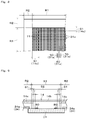
- the display means 30, as shown in Fig. 3 is provided with: a display element 31 in which a display area, which will be described later, is provided; a source line driving circuit (not shown) to drive a source line (a signal line) of the display element 31; a gate line driving circuit (not shown) to drive a gate line (a scanning line) of the display element 31; illumination means 32 which is composed of a light guide 32a, a light source 32b and a first flexible wiring board 32c or the like, for guiding illumination light to the display element 31; a resin case 33 made of a substantially flat plate-shaped white resin to hold the display element 31 and the light guide 32a; a frame body 36 composed of a front face frame 34 and a rear face frame 35 and made of an electrically conductive material constituting an exterior casing of the display means 30; and a printed wiring board 37 on which a timing controller (not shown) or the like to generate a variety of timing signals to control timings of the source line driving circuit and the gate line driving circuit is mounted.
- the metallic frame body 36 which is composed of the front face frame 34 and the rear face frame 35 paired with the front face frame 34, houses (accommodates) therein the display element 31 and the light guide 32a, the light source 32b, and the resin case 33 or the like.
- the printed wiring board 37 is fixed, by appropriately employing fixing means, to a rear face of a bottom face part, which will be described later, of the rear face frame 35.
- one or more optical means for substantially uniformly illuminate the display element 31 with backlight may be disposed between the display element 31 and the light guide 32a.
- the display element 31 is composed of a TFT-type liquid crystal display panel of a dot matrix type having a plurality of pixels 31a, for example, and is provided with a display area R1 which is capable of displaying vehicle information (predetermined information) 31b such as engine speed or average fuel consumption, fuel consumption, or ambient temperature, based on a detection signal from a variety of sensors which are mounted in a vehicle (refer to Fig. 1 and Fig. 4 ).
- vehicle information predetermined information
- one pixel 31a is composed of three subsidiary pixels, an R pixel 50, a G pixel 60, and a B pixel 70, and this pixel 31a is provided in plurality (multiply) in a matrix manner in the display area R1 of the display element 31.
- the light guide 32a is made of a substantially flat plate-shaped synthetic resin, and is disposed so as to be taken along a rear face of the display element 31. In other words, the light guide 32a is disposed in an illumination light path leading from the light source 32b to the display element 31.
- the light source 32b is composed of chip type light emitting diodes to appropriately emit color, and is made of light emitting members which are disposed to be arranged in plurality so as to be taken along one side face 32d positioned at a right side of the light guide 32a to supply illumination light to the display element 31, in Fig. 3 .
- the front face frame 34 is made of an electrically conductive member, and is configured so that: a front face part 34a press-molded in a substantial frame shape and forming an essential part thereof; and a first peripheral wall part 34b formed to be suspended from a peripheral edge of the front face part 34a toward a lower side are formed integrally with each other.
- a display window part 34c made of a substantially rectangular opening window is formed so as to correspond to the display part 31d.
- the rear face frame 35 is made of an electrically conductive material in the same manner as in the front face frame 34, and is configured so that a bottom face part 35a, which is formed in a sectional substantially recessed shape and forming an essential part thereof, and a second peripheral wall part 35b, which is formed to be protruded from a peripheral edge of this bottom face part 35a toward the first peripheral wall part 34b, are formed integrally with each other.
- a first flexible wiring board 32c is fixed by appropriately employing fixing means, and each light source 32b is mounted on an electrically conducting path (not shown) which is provided on the first flexible wiring board 32c so as to oppose to one side face 32d of the light guide 32a.
- reference numeral 37a designates a first connector to be mounted on the printed wiring board 37, and this first connector 37a and a second connector 13a which is mounted on the wiring board 13 are electrically conductively connected by way of a second flexible wiring board F.
- the display plate (the protection member) 14 to cover the display means 30 has: a flat plate-shaped light transmitting board 14b made of polycarbonate which is a base member thereof; and a non-transmitting part 14c made of a black light shielding layer to be formed to be printed on a rear face of this light transmitting board 14b.
- the non-transmitting part 14c is formed to be printed on the rear face of the light transmitting board 14b so as to correspond to a non-display area R2 except the substantially rectangular display area R1 and to a peripheral edge part S1 of the display area R1 that is positioned inside of the non-display area R2.
- the non-transmitting part 14c is formed to be printed on the rear face of the light transmitting board 14b so as to overlap with the peripheral edge part S1 of the display area R1 when the vehicular gauge D is visually recognized (viewed straight on) from the viewer side.
- a part of the light transmitting board 14b corresponding to a part of the display area R1 that is positioned inside of the peripheral edge part S1 is obtained as a print-free part at which the non-transmitting part 14c made of the light shielding layer mentioned above is not formed.
- the non-transmitting part 14c also has a function as a hiding part such that when the vehicular gauge D is visually recognized (viewed straight on) from the viewer side, the metallic frame body 36 (the front face frame 34) is made invisible.
- Fig. 6 shows a state in which, when the display element 31 and the display plate 14 are joined with each other by way of the transparent resin 40, the position of the display plate 14 with respect to the display element 31 is shifted for any reason on the order of several millimeters in the direction indicated by the arrow X from the state shown in Fig. 5 .
- the position of the display plate 14 is shifted as shown in Fig.
- the non-transmitting part 14c is formed on the light transmitting board 14b so that the non-transmitting part 14c overlaps with the peripheral edge part S1 of the display area R1, it is possible to prevent an occurrence of an abnormality on appearance that a part of the frame body 36 (the front face part 34a in the front face frame 34) is visually recognized through the valid display area S2 as a visualization part area, and it is also possible to provide a display device with a high merchantability.
- the non-transmitting part 14c is continuously provided at a position close to the needle type display part 10 as well as at a position close to the display means 20. At the position close to the needle type display part 10, the non-transmitting part 14c is formed to be printed at a rear part of the light transmitting board 14b except the region in which the indication part 14a is formed as described above. It is to be noted that the non-transmitting part 14c may be formed at a surface part of the light transmitting board 14b except the valid display area S2.
- the transparent resin 40 is made of an optical adhesive (for example, a liquid silicone-based adhesive) which is filled into the gap formed between the display means 30 and the light transmitting board 14b, a thickness thereof is on the order of 300 microns to 1,000 microns, and an index of refraction thereof is 1.45 to 1.55, which is set to be substantially equal to an index of refraction of the light transmitting board 14b that is formed of polycarbonate.
- an optical adhesive for example, a liquid silicone-based adhesive
- the transparent resin 40 is applied to at least one of the display plate 14 and the display means 30, and then, the display plate 14 and the display means 30 are bonded with each other by employing the transparent resin 40, and subsequently, the transparent resin 40 is hardened (UV-cured), whereby the display unit 20 composed of the display plate 14, the display means 30, and the transparent resin 40 can be obtained.
- the transparent resin 40 is obtained as an adhesive to absorb stretching due to a difference in linear expansion coefficient between the light transmitting board 14b that is obtained as an adhesive part to come into intimate contact with (adhere to) the transparent resin 40 and a front side polarizing member (not shown) which is provided at a front face side of the display element 31 and to harden in a shape of gel having an adhesive force (an elastic adhesive force) to an extent such that no releasing arises with the adhesive part (namely, an adhesive face between the transparent resin 40 and the light transmitting board 14b or the front side polarizing member).
- a weir-shaped part (not shown) made of a sealing member may be embedded between the non-transmitting part 14c and the front face part 34a so as to surround the transparent resin 40 so that the transparent resin 40 does not flow out toward the outside of the display means 30 (for example, toward the needle type display part 10).
- the vehicular gauge D is composed of the constituent elements as mentioned above. In such a configuration, the viewer who visually recognizes the vehicular gauge D can visually recognize (transmit) the vehicle information 31b that is displayed in the valid display area S2 of the display element 31, through the transparent resin 40, the light transmitting board 14b, and the visualization panel 18.
- the vehicular gauge D including: the display means 30 having the display element 31 in which the display area R1 capable of displaying the vehicle information 31b is provided; and the display plate (the protection member) 14 which covers the display means 30 and is joined with the display means 30 by way of the transparent resin 40 filled in the gap formed between the display means 30 and the display plate 14, the display plate 14 is provided with the light transmitting board 14b which is a base member of the display plate 14; and the non-transmitting part 14c formed on the light transmitting board 14b to overlap with the peripheral edge S1 of the display area R1.
- the present embodiment described an example in which, when the vehicular gauge D is viewed straight on from the viewer side, the peripheral edge part S1 of the display area R1 and the non-transmitting part 14c overlap with each other, for example, as shown in Fig. 7 as a modification example of the present embodiment, it may be that all of the parts of the pixel 31a indicated in a range of reference code T which is equivalent to the color display area (namely, the peripheral edge part S1 of the display area R1 and the pixel 31a that is positioned slightly more inward than the peripheral edge part S1) are displayed in black.
- the peripheral edge part S1 and the pixel 31a provided at a part of the display area R1 positioned inside of the peripheral edge part S1 is configured to be colored and displayed in black so as to have a same (similar) color as black which is a tone of the non-transmitting part 14c.
- a background color of the vehicle information 31b which will be displayed as a background color in the display area R1
- a background color of the vehicle information 31b which will be displayed as a background color in the display area R1
- a background color of the vehicle information 31b which will be displayed as a background color in the display area R1
- a longitudinal line-shaped black line 71 (indicated by the filled part in Fig. 8 ), which should not be visually recognized from the viewer side, is displayed at a leftward side of the display area R1 so as to be taken along the non-transmitting part 14c, and the quality on appearance thereof may be degraded.
- the peripheral edge part S1 and the pixel 31a that is provided at the site of the display area R1 that is positioned inside of the peripheral edge part S1 are displayed to be colored in black so as to a tone of the same (similar) color as black which is the tone of the non-transmitting part 14c, whereby all of the pixels 31a that are positioned in the color display area T are displayed in black, and the blue line 71 that has been a cause of the degradation of the quality on appearance described above is never displayed, and thus, it is possible to provide a display device with a good quality on appearance.
- a dimensional value obtained by adding the peripheral edge part S1 and the color display area T to each other is twice or more of a dimensional value of the peripheral edge part S1.
- a gradation area 80 in which a part of the display area R1 (a part of the valid display area S2) along the inside of the color display area T that is displayed to be colored (displayed in black) gradually varies from black which is a tone of the color display area T to a background color forming a background of the vehicle information 31b (herein, referred to as a white background color obtained when all of the R pixel 50, the G pixel 60, and the B pixel 70 are turned on).
- the gradation area 80 gradually varies in order of black, grey, and white in brightness thereof, as the area goes from the color display area T to the inside.
- the present invention is applicable to a display device in which: display means having a display element in which a display area capable of displaying predetermined information is provided; and a protection member to cover this display means are joined with each other by way of a transparent resin which is filled into a gap formed between the display means and the protection member.
Landscapes
- Engineering & Computer Science (AREA)
- Physics & Mathematics (AREA)
- Chemical & Material Sciences (AREA)
- Transportation (AREA)
- Mechanical Engineering (AREA)
- Combustion & Propulsion (AREA)
- General Physics & Mathematics (AREA)
- Nonlinear Science (AREA)
- Crystallography & Structural Chemistry (AREA)
- Mathematical Physics (AREA)
- Optics & Photonics (AREA)
- Theoretical Computer Science (AREA)
- Computer Hardware Design (AREA)
- Instrument Panels (AREA)
- Devices For Indicating Variable Information By Combining Individual Elements (AREA)
Applications Claiming Priority (2)
| Application Number | Priority Date | Filing Date | Title |
|---|---|---|---|
| JP2013081090A JP6120064B2 (ja) | 2013-04-09 | 2013-04-09 | 表示装置 |
| PCT/JP2014/059807 WO2014168067A1 (ja) | 2013-04-09 | 2014-04-03 | 表示装置 |
Publications (3)
| Publication Number | Publication Date |
|---|---|
| EP2985751A1 true EP2985751A1 (de) | 2016-02-17 |
| EP2985751A4 EP2985751A4 (de) | 2017-05-03 |
| EP2985751B1 EP2985751B1 (de) | 2019-12-11 |
Family
ID=51689477
Family Applications (1)
| Application Number | Title | Priority Date | Filing Date |
|---|---|---|---|
| EP14783406.3A Active EP2985751B1 (de) | 2013-04-09 | 2014-04-03 | Anzeigevorrichtung |
Country Status (6)
| Country | Link |
|---|---|
| US (1) | US20160048050A1 (de) |
| EP (1) | EP2985751B1 (de) |
| JP (1) | JP6120064B2 (de) |
| KR (1) | KR102226011B1 (de) |
| CN (1) | CN105074803B (de) |
| WO (1) | WO2014168067A1 (de) |
Families Citing this family (6)
| Publication number | Priority date | Publication date | Assignee | Title |
|---|---|---|---|---|
| DE102014201885A1 (de) * | 2014-02-03 | 2015-08-06 | Johnson Controls Automotive Electronics Gmbh | Abdeckscheibe für mindestens ein Anzeigeinstrument in einem Fahrzeug |
| JP6201810B2 (ja) * | 2014-02-26 | 2017-09-27 | 日本精機株式会社 | 車両用表示装置 |
| KR20170007610A (ko) * | 2015-07-09 | 2017-01-19 | 삼성디스플레이 주식회사 | 표시 장치 |
| USD809604S1 (en) * | 2015-07-14 | 2018-02-06 | Aldo Rene Iglesias | Label for a bottle |
| US20200001717A1 (en) * | 2017-03-06 | 2020-01-02 | Nippon Seiki Co., Ltd. | Display device |
| JP6425762B2 (ja) * | 2017-04-26 | 2018-11-21 | 三菱電機株式会社 | 自動二輪車の表示装置 |
Family Cites Families (12)
| Publication number | Priority date | Publication date | Assignee | Title |
|---|---|---|---|---|
| US5365357A (en) * | 1988-04-21 | 1994-11-15 | Asahi Glass Company Ltd. | Color liquid crystal display having color filters and light blocking layers in the periphery |
| US5017194A (en) * | 1989-01-19 | 1991-05-21 | The United States Of America, As Represented By The Secretary Of Agriculture | Sequential oxidative and reductive bleaching of pigmented and unpigmented fibers |
| JP3028272B2 (ja) * | 1993-12-24 | 2000-04-04 | キヤノン株式会社 | 液晶表示装置 |
| US5936694A (en) * | 1995-04-26 | 1999-08-10 | Canon Kabushiki Kaisha | Liquid crystal device and process for producing same |
| KR101146536B1 (ko) * | 2005-06-27 | 2012-05-25 | 삼성전자주식회사 | 표시패널, 이의 제조방법 및 이를 갖는 표시장치 |
| JP4483833B2 (ja) * | 2005-09-22 | 2010-06-16 | エプソンイメージングデバイス株式会社 | 電気光学装置、電子機器、保護部材、保護部材の製造方法 |
| CN201054259Y (zh) * | 2007-05-11 | 2008-04-30 | 邝栋林 | 贴密式液晶显示器保护面板 |
| JP4494446B2 (ja) * | 2007-09-12 | 2010-06-30 | 株式会社 日立ディスプレイズ | 表示装置 |
| JP5381446B2 (ja) | 2009-07-21 | 2014-01-08 | 日本精機株式会社 | 表示装置 |
| JP5426426B2 (ja) * | 2010-02-19 | 2014-02-26 | 株式会社ジャパンディスプレイ | 表示装置及び液晶表示装置並びにこれらの製造方法 |
| JP5590403B2 (ja) * | 2011-01-27 | 2014-09-17 | 日本精機株式会社 | 液晶表示装置 |
| JP2012173489A (ja) * | 2011-02-21 | 2012-09-10 | Seiko Epson Corp | 電気光学装置、電気光学装置の駆動方法および電子機器 |
-
2013
- 2013-04-09 JP JP2013081090A patent/JP6120064B2/ja active Active
-
2014
- 2014-04-03 EP EP14783406.3A patent/EP2985751B1/de active Active
- 2014-04-03 KR KR1020157029731A patent/KR102226011B1/ko active Active
- 2014-04-03 CN CN201480018757.1A patent/CN105074803B/zh active Active
- 2014-04-03 WO PCT/JP2014/059807 patent/WO2014168067A1/ja not_active Ceased
- 2014-04-03 US US14/783,411 patent/US20160048050A1/en not_active Abandoned
Also Published As
| Publication number | Publication date |
|---|---|
| KR20150140690A (ko) | 2015-12-16 |
| WO2014168067A1 (ja) | 2014-10-16 |
| CN105074803A (zh) | 2015-11-18 |
| CN105074803B (zh) | 2018-01-02 |
| EP2985751A4 (de) | 2017-05-03 |
| US20160048050A1 (en) | 2016-02-18 |
| EP2985751B1 (de) | 2019-12-11 |
| JP2014202685A (ja) | 2014-10-27 |
| KR102226011B1 (ko) | 2021-03-09 |
| JP6120064B2 (ja) | 2017-04-26 |
Similar Documents
| Publication | Publication Date | Title |
|---|---|---|
| EP2985751B1 (de) | Anzeigevorrichtung | |
| CN105074393B (zh) | 显示装置 | |
| CN101795925B (zh) | 用于机动车辆的方向盘组件 | |
| JP5963849B2 (ja) | 操作パネルおよびこれを備える情報機器 | |
| CN101382255A (zh) | 背光单元和显示装置 | |
| WO2018056076A1 (ja) | 表示装置 | |
| CN106945524B (zh) | 用于机动车的显示设备 | |
| JP2018179741A (ja) | 表示装置 | |
| JP2015094905A (ja) | 表示装置 | |
| JP6597230B2 (ja) | 表示装置 | |
| KR20150105707A (ko) | 디스플레이 기기 | |
| WO2018139432A1 (ja) | 表示装置 | |
| JP2012189666A (ja) | 表示装置 | |
| JP2019207268A (ja) | 表示装置 | |
| JP7004213B2 (ja) | 表示装置 | |
| JP5136153B2 (ja) | 車両用表示装置 | |
| JP2014211599A (ja) | 表示装置 | |
| JP2021047243A (ja) | 表示装置 | |
| JP5258632B2 (ja) | 計器 | |
| JP2020112759A (ja) | 表示装置 | |
| JP7245436B2 (ja) | 表示装置 | |
| WO2021251350A1 (ja) | 表示装置 | |
| JP2018189401A (ja) | 表示装置 | |
| JP6248693B2 (ja) | 表示装置 | |
| JP2020197623A (ja) | 表示装置 |
Legal Events
| Date | Code | Title | Description |
|---|---|---|---|
| PUAI | Public reference made under article 153(3) epc to a published international application that has entered the european phase |
Free format text: ORIGINAL CODE: 0009012 |
|
| 17P | Request for examination filed |
Effective date: 20151021 |
|
| AK | Designated contracting states |
Kind code of ref document: A1 Designated state(s): AL AT BE BG CH CY CZ DE DK EE ES FI FR GB GR HR HU IE IS IT LI LT LU LV MC MK MT NL NO PL PT RO RS SE SI SK SM TR |
|
| AX | Request for extension of the european patent |
Extension state: BA ME |
|
| DAX | Request for extension of the european patent (deleted) | ||
| A4 | Supplementary search report drawn up and despatched |
Effective date: 20170330 |
|
| RIC1 | Information provided on ipc code assigned before grant |
Ipc: B60K 35/00 20060101ALI20170325BHEP Ipc: G01D 13/04 20060101ALI20170325BHEP Ipc: G09F 9/00 20060101AFI20170325BHEP |
|
| GRAP | Despatch of communication of intention to grant a patent |
Free format text: ORIGINAL CODE: EPIDOSNIGR1 |
|
| STAA | Information on the status of an ep patent application or granted ep patent |
Free format text: STATUS: GRANT OF PATENT IS INTENDED |
|
| INTG | Intention to grant announced |
Effective date: 20190710 |
|
| GRAS | Grant fee paid |
Free format text: ORIGINAL CODE: EPIDOSNIGR3 |
|
| GRAA | (expected) grant |
Free format text: ORIGINAL CODE: 0009210 |
|
| STAA | Information on the status of an ep patent application or granted ep patent |
Free format text: STATUS: THE PATENT HAS BEEN GRANTED |
|
| AK | Designated contracting states |
Kind code of ref document: B1 Designated state(s): AL AT BE BG CH CY CZ DE DK EE ES FI FR GB GR HR HU IE IS IT LI LT LU LV MC MK MT NL NO PL PT RO RS SE SI SK SM TR |
|
| REG | Reference to a national code |
Ref country code: GB Ref legal event code: FG4D |
|
| REG | Reference to a national code |
Ref country code: CH Ref legal event code: EP |
|
| REG | Reference to a national code |
Ref country code: AT Ref legal event code: REF Ref document number: 1212977 Country of ref document: AT Kind code of ref document: T Effective date: 20191215 |
|
| REG | Reference to a national code |
Ref country code: DE Ref legal event code: R096 Ref document number: 602014058291 Country of ref document: DE |
|
| REG | Reference to a national code |
Ref country code: IE Ref legal event code: FG4D |
|
| REG | Reference to a national code |
Ref country code: NL Ref legal event code: MP Effective date: 20191211 |
|
| REG | Reference to a national code |
Ref country code: LT Ref legal event code: MG4D |
|
| PG25 | Lapsed in a contracting state [announced via postgrant information from national office to epo] |
Ref country code: LV Free format text: LAPSE BECAUSE OF FAILURE TO SUBMIT A TRANSLATION OF THE DESCRIPTION OR TO PAY THE FEE WITHIN THE PRESCRIBED TIME-LIMIT Effective date: 20191211 Ref country code: SE Free format text: LAPSE BECAUSE OF FAILURE TO SUBMIT A TRANSLATION OF THE DESCRIPTION OR TO PAY THE FEE WITHIN THE PRESCRIBED TIME-LIMIT Effective date: 20191211 Ref country code: LT Free format text: LAPSE BECAUSE OF FAILURE TO SUBMIT A TRANSLATION OF THE DESCRIPTION OR TO PAY THE FEE WITHIN THE PRESCRIBED TIME-LIMIT Effective date: 20191211 Ref country code: BG Free format text: LAPSE BECAUSE OF FAILURE TO SUBMIT A TRANSLATION OF THE DESCRIPTION OR TO PAY THE FEE WITHIN THE PRESCRIBED TIME-LIMIT Effective date: 20200311 Ref country code: FI Free format text: LAPSE BECAUSE OF FAILURE TO SUBMIT A TRANSLATION OF THE DESCRIPTION OR TO PAY THE FEE WITHIN THE PRESCRIBED TIME-LIMIT Effective date: 20191211 Ref country code: GR Free format text: LAPSE BECAUSE OF FAILURE TO SUBMIT A TRANSLATION OF THE DESCRIPTION OR TO PAY THE FEE WITHIN THE PRESCRIBED TIME-LIMIT Effective date: 20200312 Ref country code: NO Free format text: LAPSE BECAUSE OF FAILURE TO SUBMIT A TRANSLATION OF THE DESCRIPTION OR TO PAY THE FEE WITHIN THE PRESCRIBED TIME-LIMIT Effective date: 20200311 |
|
| PG25 | Lapsed in a contracting state [announced via postgrant information from national office to epo] |
Ref country code: HR Free format text: LAPSE BECAUSE OF FAILURE TO SUBMIT A TRANSLATION OF THE DESCRIPTION OR TO PAY THE FEE WITHIN THE PRESCRIBED TIME-LIMIT Effective date: 20191211 Ref country code: RS Free format text: LAPSE BECAUSE OF FAILURE TO SUBMIT A TRANSLATION OF THE DESCRIPTION OR TO PAY THE FEE WITHIN THE PRESCRIBED TIME-LIMIT Effective date: 20191211 |
|
| PG25 | Lapsed in a contracting state [announced via postgrant information from national office to epo] |
Ref country code: AL Free format text: LAPSE BECAUSE OF FAILURE TO SUBMIT A TRANSLATION OF THE DESCRIPTION OR TO PAY THE FEE WITHIN THE PRESCRIBED TIME-LIMIT Effective date: 20191211 |
|
| PG25 | Lapsed in a contracting state [announced via postgrant information from national office to epo] |
Ref country code: RO Free format text: LAPSE BECAUSE OF FAILURE TO SUBMIT A TRANSLATION OF THE DESCRIPTION OR TO PAY THE FEE WITHIN THE PRESCRIBED TIME-LIMIT Effective date: 20191211 Ref country code: CZ Free format text: LAPSE BECAUSE OF FAILURE TO SUBMIT A TRANSLATION OF THE DESCRIPTION OR TO PAY THE FEE WITHIN THE PRESCRIBED TIME-LIMIT Effective date: 20191211 Ref country code: ES Free format text: LAPSE BECAUSE OF FAILURE TO SUBMIT A TRANSLATION OF THE DESCRIPTION OR TO PAY THE FEE WITHIN THE PRESCRIBED TIME-LIMIT Effective date: 20191211 Ref country code: NL Free format text: LAPSE BECAUSE OF FAILURE TO SUBMIT A TRANSLATION OF THE DESCRIPTION OR TO PAY THE FEE WITHIN THE PRESCRIBED TIME-LIMIT Effective date: 20191211 Ref country code: PT Free format text: LAPSE BECAUSE OF FAILURE TO SUBMIT A TRANSLATION OF THE DESCRIPTION OR TO PAY THE FEE WITHIN THE PRESCRIBED TIME-LIMIT Effective date: 20200506 Ref country code: EE Free format text: LAPSE BECAUSE OF FAILURE TO SUBMIT A TRANSLATION OF THE DESCRIPTION OR TO PAY THE FEE WITHIN THE PRESCRIBED TIME-LIMIT Effective date: 20191211 |
|
| PG25 | Lapsed in a contracting state [announced via postgrant information from national office to epo] |
Ref country code: IS Free format text: LAPSE BECAUSE OF FAILURE TO SUBMIT A TRANSLATION OF THE DESCRIPTION OR TO PAY THE FEE WITHIN THE PRESCRIBED TIME-LIMIT Effective date: 20200411 Ref country code: SK Free format text: LAPSE BECAUSE OF FAILURE TO SUBMIT A TRANSLATION OF THE DESCRIPTION OR TO PAY THE FEE WITHIN THE PRESCRIBED TIME-LIMIT Effective date: 20191211 Ref country code: SM Free format text: LAPSE BECAUSE OF FAILURE TO SUBMIT A TRANSLATION OF THE DESCRIPTION OR TO PAY THE FEE WITHIN THE PRESCRIBED TIME-LIMIT Effective date: 20191211 |
|
| REG | Reference to a national code |
Ref country code: DE Ref legal event code: R097 Ref document number: 602014058291 Country of ref document: DE |
|
| REG | Reference to a national code |
Ref country code: AT Ref legal event code: MK05 Ref document number: 1212977 Country of ref document: AT Kind code of ref document: T Effective date: 20191211 |
|
| PLBE | No opposition filed within time limit |
Free format text: ORIGINAL CODE: 0009261 |
|
| STAA | Information on the status of an ep patent application or granted ep patent |
Free format text: STATUS: NO OPPOSITION FILED WITHIN TIME LIMIT |
|
| PG25 | Lapsed in a contracting state [announced via postgrant information from national office to epo] |
Ref country code: DK Free format text: LAPSE BECAUSE OF FAILURE TO SUBMIT A TRANSLATION OF THE DESCRIPTION OR TO PAY THE FEE WITHIN THE PRESCRIBED TIME-LIMIT Effective date: 20191211 |
|
| 26N | No opposition filed |
Effective date: 20200914 |
|
| PG25 | Lapsed in a contracting state [announced via postgrant information from national office to epo] |
Ref country code: MC Free format text: LAPSE BECAUSE OF FAILURE TO SUBMIT A TRANSLATION OF THE DESCRIPTION OR TO PAY THE FEE WITHIN THE PRESCRIBED TIME-LIMIT Effective date: 20191211 Ref country code: SI Free format text: LAPSE BECAUSE OF FAILURE TO SUBMIT A TRANSLATION OF THE DESCRIPTION OR TO PAY THE FEE WITHIN THE PRESCRIBED TIME-LIMIT Effective date: 20191211 Ref country code: AT Free format text: LAPSE BECAUSE OF FAILURE TO SUBMIT A TRANSLATION OF THE DESCRIPTION OR TO PAY THE FEE WITHIN THE PRESCRIBED TIME-LIMIT Effective date: 20191211 |
|
| REG | Reference to a national code |
Ref country code: CH Ref legal event code: PL |
|
| PG25 | Lapsed in a contracting state [announced via postgrant information from national office to epo] |
Ref country code: LU Free format text: LAPSE BECAUSE OF NON-PAYMENT OF DUE FEES Effective date: 20200403 Ref country code: CH Free format text: LAPSE BECAUSE OF NON-PAYMENT OF DUE FEES Effective date: 20200430 Ref country code: LI Free format text: LAPSE BECAUSE OF NON-PAYMENT OF DUE FEES Effective date: 20200430 |
|
| REG | Reference to a national code |
Ref country code: BE Ref legal event code: MM Effective date: 20200430 |
|
| PG25 | Lapsed in a contracting state [announced via postgrant information from national office to epo] |
Ref country code: BE Free format text: LAPSE BECAUSE OF NON-PAYMENT OF DUE FEES Effective date: 20200430 Ref country code: PL Free format text: LAPSE BECAUSE OF FAILURE TO SUBMIT A TRANSLATION OF THE DESCRIPTION OR TO PAY THE FEE WITHIN THE PRESCRIBED TIME-LIMIT Effective date: 20191211 |
|
| PG25 | Lapsed in a contracting state [announced via postgrant information from national office to epo] |
Ref country code: IE Free format text: LAPSE BECAUSE OF NON-PAYMENT OF DUE FEES Effective date: 20200403 |
|
| PG25 | Lapsed in a contracting state [announced via postgrant information from national office to epo] |
Ref country code: TR Free format text: LAPSE BECAUSE OF FAILURE TO SUBMIT A TRANSLATION OF THE DESCRIPTION OR TO PAY THE FEE WITHIN THE PRESCRIBED TIME-LIMIT Effective date: 20191211 Ref country code: MT Free format text: LAPSE BECAUSE OF FAILURE TO SUBMIT A TRANSLATION OF THE DESCRIPTION OR TO PAY THE FEE WITHIN THE PRESCRIBED TIME-LIMIT Effective date: 20191211 Ref country code: CY Free format text: LAPSE BECAUSE OF FAILURE TO SUBMIT A TRANSLATION OF THE DESCRIPTION OR TO PAY THE FEE WITHIN THE PRESCRIBED TIME-LIMIT Effective date: 20191211 |
|
| PGFP | Annual fee paid to national office [announced via postgrant information from national office to epo] |
Ref country code: IT Payment date: 20220310 Year of fee payment: 9 |
|
| PG25 | Lapsed in a contracting state [announced via postgrant information from national office to epo] |
Ref country code: MK Free format text: LAPSE BECAUSE OF FAILURE TO SUBMIT A TRANSLATION OF THE DESCRIPTION OR TO PAY THE FEE WITHIN THE PRESCRIBED TIME-LIMIT Effective date: 20191211 |
|
| PG25 | Lapsed in a contracting state [announced via postgrant information from national office to epo] |
Ref country code: IT Free format text: LAPSE BECAUSE OF NON-PAYMENT OF DUE FEES Effective date: 20230403 |
|
| PGFP | Annual fee paid to national office [announced via postgrant information from national office to epo] |
Ref country code: FR Payment date: 20250310 Year of fee payment: 12 |
|
| PGFP | Annual fee paid to national office [announced via postgrant information from national office to epo] |
Ref country code: GB Payment date: 20250227 Year of fee payment: 12 |
|
| PGFP | Annual fee paid to national office [announced via postgrant information from national office to epo] |
Ref country code: DE Payment date: 20250305 Year of fee payment: 12 |