EP2985051A1 - Katheterschaft und katheter sowie verfahren zur herstellung derselben - Google Patents
Katheterschaft und katheter sowie verfahren zur herstellung derselben Download PDFInfo
- Publication number
- EP2985051A1 EP2985051A1 EP15170754.4A EP15170754A EP2985051A1 EP 2985051 A1 EP2985051 A1 EP 2985051A1 EP 15170754 A EP15170754 A EP 15170754A EP 2985051 A1 EP2985051 A1 EP 2985051A1
- Authority
- EP
- European Patent Office
- Prior art keywords
- tube
- catheter
- catheter shaft
- proximal
- distal
- Prior art date
- Legal status (The legal status is an assumption and is not a legal conclusion. Google has not performed a legal analysis and makes no representation as to the accuracy of the status listed.)
- Granted
Links
Images




Classifications
-
- A—HUMAN NECESSITIES
- A61—MEDICAL OR VETERINARY SCIENCE; HYGIENE
- A61M—DEVICES FOR INTRODUCING MEDIA INTO, OR ONTO, THE BODY; DEVICES FOR TRANSDUCING BODY MEDIA OR FOR TAKING MEDIA FROM THE BODY; DEVICES FOR PRODUCING OR ENDING SLEEP OR STUPOR
- A61M25/00—Catheters; Hollow probes
- A61M25/0021—Catheters; Hollow probes characterised by the form of the tubing
- A61M25/0023—Catheters; Hollow probes characterised by the form of the tubing by the form of the lumen, e.g. cross-section, variable diameter
- A61M25/0026—Multi-lumen catheters with stationary elements
-
- A—HUMAN NECESSITIES
- A61—MEDICAL OR VETERINARY SCIENCE; HYGIENE
- A61M—DEVICES FOR INTRODUCING MEDIA INTO, OR ONTO, THE BODY; DEVICES FOR TRANSDUCING BODY MEDIA OR FOR TAKING MEDIA FROM THE BODY; DEVICES FOR PRODUCING OR ENDING SLEEP OR STUPOR
- A61M25/00—Catheters; Hollow probes
- A61M25/0009—Making of catheters or other medical or surgical tubes
-
- A—HUMAN NECESSITIES
- A61—MEDICAL OR VETERINARY SCIENCE; HYGIENE
- A61M—DEVICES FOR INTRODUCING MEDIA INTO, OR ONTO, THE BODY; DEVICES FOR TRANSDUCING BODY MEDIA OR FOR TAKING MEDIA FROM THE BODY; DEVICES FOR PRODUCING OR ENDING SLEEP OR STUPOR
- A61M25/00—Catheters; Hollow probes
- A61M25/0097—Catheters; Hollow probes characterised by the hub
-
- A—HUMAN NECESSITIES
- A61—MEDICAL OR VETERINARY SCIENCE; HYGIENE
- A61M—DEVICES FOR INTRODUCING MEDIA INTO, OR ONTO, THE BODY; DEVICES FOR TRANSDUCING BODY MEDIA OR FOR TAKING MEDIA FROM THE BODY; DEVICES FOR PRODUCING OR ENDING SLEEP OR STUPOR
- A61M39/00—Tubes, tube connectors, tube couplings, valves, access sites or the like, specially adapted for medical use
- A61M39/10—Tube connectors or tube couplings
-
- A—HUMAN NECESSITIES
- A61—MEDICAL OR VETERINARY SCIENCE; HYGIENE
- A61M—DEVICES FOR INTRODUCING MEDIA INTO, OR ONTO, THE BODY; DEVICES FOR TRANSDUCING BODY MEDIA OR FOR TAKING MEDIA FROM THE BODY; DEVICES FOR PRODUCING OR ENDING SLEEP OR STUPOR
- A61M39/00—Tubes, tube connectors, tube couplings, valves, access sites or the like, specially adapted for medical use
- A61M39/10—Tube connectors or tube couplings
- A61M39/105—Multi-channel connectors or couplings, e.g. for connecting multi-lumen tubes
-
- A—HUMAN NECESSITIES
- A61—MEDICAL OR VETERINARY SCIENCE; HYGIENE
- A61M—DEVICES FOR INTRODUCING MEDIA INTO, OR ONTO, THE BODY; DEVICES FOR TRANSDUCING BODY MEDIA OR FOR TAKING MEDIA FROM THE BODY; DEVICES FOR PRODUCING OR ENDING SLEEP OR STUPOR
- A61M25/00—Catheters; Hollow probes
- A61M25/0021—Catheters; Hollow probes characterised by the form of the tubing
- A61M25/0023—Catheters; Hollow probes characterised by the form of the tubing by the form of the lumen, e.g. cross-section, variable diameter
- A61M25/0026—Multi-lumen catheters with stationary elements
- A61M2025/0034—Multi-lumen catheters with stationary elements characterized by elements which are assembled, connected or fused, e.g. splittable tubes, outer sheaths creating lumina or separate cores
-
- A—HUMAN NECESSITIES
- A61—MEDICAL OR VETERINARY SCIENCE; HYGIENE
- A61M—DEVICES FOR INTRODUCING MEDIA INTO, OR ONTO, THE BODY; DEVICES FOR TRANSDUCING BODY MEDIA OR FOR TAKING MEDIA FROM THE BODY; DEVICES FOR PRODUCING OR ENDING SLEEP OR STUPOR
- A61M25/00—Catheters; Hollow probes
- A61M25/0021—Catheters; Hollow probes characterised by the form of the tubing
- A61M25/0023—Catheters; Hollow probes characterised by the form of the tubing by the form of the lumen, e.g. cross-section, variable diameter
- A61M25/0026—Multi-lumen catheters with stationary elements
- A61M2025/0039—Multi-lumen catheters with stationary elements characterized by lumina being arranged coaxially
-
- A—HUMAN NECESSITIES
- A61—MEDICAL OR VETERINARY SCIENCE; HYGIENE
- A61M—DEVICES FOR INTRODUCING MEDIA INTO, OR ONTO, THE BODY; DEVICES FOR TRANSDUCING BODY MEDIA OR FOR TAKING MEDIA FROM THE BODY; DEVICES FOR PRODUCING OR ENDING SLEEP OR STUPOR
- A61M25/00—Catheters; Hollow probes
- A61M2025/0098—Catheters; Hollow probes having a strain relief at the proximal end, e.g. sleeve
-
- A—HUMAN NECESSITIES
- A61—MEDICAL OR VETERINARY SCIENCE; HYGIENE
- A61M—DEVICES FOR INTRODUCING MEDIA INTO, OR ONTO, THE BODY; DEVICES FOR TRANSDUCING BODY MEDIA OR FOR TAKING MEDIA FROM THE BODY; DEVICES FOR PRODUCING OR ENDING SLEEP OR STUPOR
- A61M39/00—Tubes, tube connectors, tube couplings, valves, access sites or the like, specially adapted for medical use
- A61M39/10—Tube connectors or tube couplings
- A61M2039/1027—Quick-acting type connectors
-
- A—HUMAN NECESSITIES
- A61—MEDICAL OR VETERINARY SCIENCE; HYGIENE
- A61M—DEVICES FOR INTRODUCING MEDIA INTO, OR ONTO, THE BODY; DEVICES FOR TRANSDUCING BODY MEDIA OR FOR TAKING MEDIA FROM THE BODY; DEVICES FOR PRODUCING OR ENDING SLEEP OR STUPOR
- A61M25/00—Catheters; Hollow probes
- A61M25/0009—Making of catheters or other medical or surgical tubes
- A61M25/0014—Connecting a tube to a hub
-
- A—HUMAN NECESSITIES
- A61—MEDICAL OR VETERINARY SCIENCE; HYGIENE
- A61M—DEVICES FOR INTRODUCING MEDIA INTO, OR ONTO, THE BODY; DEVICES FOR TRANSDUCING BODY MEDIA OR FOR TAKING MEDIA FROM THE BODY; DEVICES FOR PRODUCING OR ENDING SLEEP OR STUPOR
- A61M25/00—Catheters; Hollow probes
- A61M25/01—Introducing, guiding, advancing, emplacing or holding catheters
- A61M25/09—Guide wires
-
- A—HUMAN NECESSITIES
- A61—MEDICAL OR VETERINARY SCIENCE; HYGIENE
- A61M—DEVICES FOR INTRODUCING MEDIA INTO, OR ONTO, THE BODY; DEVICES FOR TRANSDUCING BODY MEDIA OR FOR TAKING MEDIA FROM THE BODY; DEVICES FOR PRODUCING OR ENDING SLEEP OR STUPOR
- A61M25/00—Catheters; Hollow probes
- A61M25/10—Balloon catheters
- A61M25/104—Balloon catheters used for angioplasty
-
- B—PERFORMING OPERATIONS; TRANSPORTING
- B29—WORKING OF PLASTICS; WORKING OF SUBSTANCES IN A PLASTIC STATE IN GENERAL
- B29C—SHAPING OR JOINING OF PLASTICS; SHAPING OF MATERIAL IN A PLASTIC STATE, NOT OTHERWISE PROVIDED FOR; AFTER-TREATMENT OF THE SHAPED PRODUCTS, e.g. REPAIRING
- B29C65/00—Joining or sealing of preformed parts, e.g. welding of plastics materials; Apparatus therefor
- B29C65/02—Joining or sealing of preformed parts, e.g. welding of plastics materials; Apparatus therefor by heating, with or without pressure
- B29C65/14—Joining or sealing of preformed parts, e.g. welding of plastics materials; Apparatus therefor by heating, with or without pressure using wave energy, i.e. electromagnetic radiation, or particle radiation
- B29C65/16—Laser beams
- B29C65/1677—Laser beams making use of an absorber or impact modifier
- B29C65/1683—Laser beams making use of an absorber or impact modifier coated on the article
-
- B—PERFORMING OPERATIONS; TRANSPORTING
- B29—WORKING OF PLASTICS; WORKING OF SUBSTANCES IN A PLASTIC STATE IN GENERAL
- B29C—SHAPING OR JOINING OF PLASTICS; SHAPING OF MATERIAL IN A PLASTIC STATE, NOT OTHERWISE PROVIDED FOR; AFTER-TREATMENT OF THE SHAPED PRODUCTS, e.g. REPAIRING
- B29C66/00—General aspects of processes or apparatus for joining preformed parts
- B29C66/01—General aspects dealing with the joint area or with the area to be joined
- B29C66/05—Particular design of joint configurations
- B29C66/10—Particular design of joint configurations particular design of the joint cross-sections
- B29C66/11—Joint cross-sections comprising a single joint-segment, i.e. one of the parts to be joined comprising a single joint-segment in the joint cross-section
- B29C66/112—Single lapped joints
- B29C66/1122—Single lap to lap joints, i.e. overlap joints
-
- B—PERFORMING OPERATIONS; TRANSPORTING
- B29—WORKING OF PLASTICS; WORKING OF SUBSTANCES IN A PLASTIC STATE IN GENERAL
- B29C—SHAPING OR JOINING OF PLASTICS; SHAPING OF MATERIAL IN A PLASTIC STATE, NOT OTHERWISE PROVIDED FOR; AFTER-TREATMENT OF THE SHAPED PRODUCTS, e.g. REPAIRING
- B29C66/00—General aspects of processes or apparatus for joining preformed parts
- B29C66/50—General aspects of joining tubular articles; General aspects of joining long products, i.e. bars or profiled elements; General aspects of joining single elements to tubular articles, hollow articles or bars; General aspects of joining several hollow-preforms to form hollow or tubular articles
- B29C66/51—Joining tubular articles, profiled elements or bars; Joining single elements to tubular articles, hollow articles or bars; Joining several hollow-preforms to form hollow or tubular articles
- B29C66/52—Joining tubular articles, bars or profiled elements
- B29C66/522—Joining tubular articles
- B29C66/5227—Joining tubular articles for forming multi-tubular articles by longitudinally joining elementary tubular articles wall-to-wall (e.g. joining the wall of a first tubular article to the wall of a second tubular article) or for forming multilayer tubular articles
- B29C66/52271—Joining tubular articles for forming multi-tubular articles by longitudinally joining elementary tubular articles wall-to-wall (e.g. joining the wall of a first tubular article to the wall of a second tubular article) or for forming multilayer tubular articles one tubular article being placed inside the other
-
- B—PERFORMING OPERATIONS; TRANSPORTING
- B29—WORKING OF PLASTICS; WORKING OF SUBSTANCES IN A PLASTIC STATE IN GENERAL
- B29C—SHAPING OR JOINING OF PLASTICS; SHAPING OF MATERIAL IN A PLASTIC STATE, NOT OTHERWISE PROVIDED FOR; AFTER-TREATMENT OF THE SHAPED PRODUCTS, e.g. REPAIRING
- B29C66/00—General aspects of processes or apparatus for joining preformed parts
- B29C66/70—General aspects of processes or apparatus for joining preformed parts characterised by the composition, physical properties or the structure of the material of the parts to be joined; Joining with non-plastics material
- B29C66/71—General aspects of processes or apparatus for joining preformed parts characterised by the composition, physical properties or the structure of the material of the parts to be joined; Joining with non-plastics material characterised by the composition of the plastics material of the parts to be joined
-
- B—PERFORMING OPERATIONS; TRANSPORTING
- B29—WORKING OF PLASTICS; WORKING OF SUBSTANCES IN A PLASTIC STATE IN GENERAL
- B29C—SHAPING OR JOINING OF PLASTICS; SHAPING OF MATERIAL IN A PLASTIC STATE, NOT OTHERWISE PROVIDED FOR; AFTER-TREATMENT OF THE SHAPED PRODUCTS, e.g. REPAIRING
- B29C66/00—General aspects of processes or apparatus for joining preformed parts
- B29C66/70—General aspects of processes or apparatus for joining preformed parts characterised by the composition, physical properties or the structure of the material of the parts to be joined; Joining with non-plastics material
- B29C66/71—General aspects of processes or apparatus for joining preformed parts characterised by the composition, physical properties or the structure of the material of the parts to be joined; Joining with non-plastics material characterised by the composition of the plastics material of the parts to be joined
- B29C66/712—General aspects of processes or apparatus for joining preformed parts characterised by the composition, physical properties or the structure of the material of the parts to be joined; Joining with non-plastics material characterised by the composition of the plastics material of the parts to be joined the composition of one of the parts to be joined being different from the composition of the other part
-
- B—PERFORMING OPERATIONS; TRANSPORTING
- B29—WORKING OF PLASTICS; WORKING OF SUBSTANCES IN A PLASTIC STATE IN GENERAL
- B29L—INDEXING SCHEME ASSOCIATED WITH SUBCLASS B29C, RELATING TO PARTICULAR ARTICLES
- B29L2031/00—Other particular articles
- B29L2031/753—Medical equipment; Accessories therefor
- B29L2031/7542—Catheters
Definitions
- the present invention relates to a catheter shaft and a catheter and to a method for producing such a catheter shaft or catheter.
- Catheters have tubes or tubing of various diameters in the region of their shaft, which can be introduced into the respective body cavity to be treated.
- so-called balloon catheters are mainly used in angioplasty for the dilation or reopening of a vessel (percutaneous transluminal coronary angioplasty - PTCA, also percutaneous coronary intervention or percutaneous coronary intervention - PCI).
- a balloon catheter has a shaft which has a first non-dilated balloon in a predetermined area.
- a guidewire is first inserted into the vessel to be treated.
- the stem of the balloon catheter is advanced along the guidewire to the site of the vessel to be treated so that the balloon is placed in the area of the site of the vessel to be treated, e.g.
- balloon catheters may also be used to deliver intraluminal endoprostheses to a site to be treated in a body cavity.
- Such a catheter usually has, in addition to its shaft, at its proximal end a connecting piece, which serves for connection of the catheter to the catheter control and possibly the fluid supply.
- the fitting is connected to the catheter shaft.
- the distal end of the catheter shaft is also referred to as a catheter tip.
- the first lumen for receiving the guide wire and the second lumen for the passage of a liquid or a gas is used.
- the first lumen may be used for the removal of blood from the patient's body and the second lumen for the return of the purified blood.
- Such a multi-lumen catheter is in the document WO 98/41277 A1 described.
- the shaft has two lumens, basically distinguish two types of shanks.
- first lumen and the second lumen are arranged side by side, separated only by a partition wall.
- two cylindrical lumens are provided in hollow cylindrical elements, wherein the smaller hollow cylindrical member (inner tube) is disposed within the lumen of the larger hollow cylinder (outer tube).
- the publication US 6,248,092 B1 shows a coaxial shaft construction.
- an inner tube for the balloon segment and, in many cases, a guide wire lumen extension must be attached to the stem for PTCA application to allow the guidewire to pass through the entire catheter (from the fitting to the catheter tip).
- the two-lumen design also has the disadvantage that in the region in which the extension is attached to the shaft, smaller constrictions and indurations of the guide wire lumen occur, which can affect the push and trackability. In addition, there is a risk of a leak in this area. Since the material properties of the shaft have to meet all the requirements of the system, often only a compromise between bursting strength, FD friction and flexibility can be made.
- the conventional coaxial shaft construction is disadvantageously characterized in that the diameter of the shaft profile is comparatively large.
- the push properties at the catheter tip deteriorate due to the design.
- the conventional coaxial design also has the disadvantage that with the same dimensions, a higher deflation time is achieved by higher fluid friction in comparison to the two-line design. Furthermore, since there is no connection between the inner and outer tubes over a large part of the shaft, relative movements of the interleaved cylindrical elements can occur under load, which can adversely affect the track / push properties of the catheter.
- the object is therefore to improve the properties of the catheter discussed above and to provide a cost-effective method for the production of such a catheter.
- a catheter shaft having a first tube forming a first lumen and a second tube forming a second lumen and at least partially disposed within the first tube.
- the second tube is at least partially welded with its outer surface (lateral surface) with the inner surface of the first tube.
- the inner diameter of the first tube must be greater than the outer diameter of the second tube.
- the outer diameter of the second tube and the inner diameter of the first tube form a ratio that is between 0.4 and 0.95, more preferably between 0.6 and 0.9. That the outer diameter of the second, inner tube is at least 0.4 times, preferably 0.6 times, the inner diameter of the first outer tube and at most 0.95 times, preferably 0.9 times, the inner diameter of the first, outer tube.
- the (inner) lumen of the first tube preferably forms the inflation lumen, while the (inner) lumen of the second tube, ie the smaller lumen, preferably represents the guidewire lumen.
- Such a construction of a catheter shaft simplifies system assembly, thus reducing the cost of manufacturing a catheter and producing less waste.
- the use of two hoses, which are arranged one inside the other, also improves the FD mobility since the guide wire lumen is completely homogeneous and round.
- the deflation time can be reduced and an increased push can be achieved.
- the first tube and the second tube are arranged in one another such that the longitudinal axes of the tubes, which preferably each have a circular cross section, run parallel to one another.
- Other cross-sectional shapes than the circular shape for the first tube and / or the second tube are also conceivable (for example, rectangular cross section).
- the weld extends parallel to the longitudinal axis of the first tube and / or the second tube.
- the first tube prefferably has a laser-active material at least in the area of its inner surface and / or the second tube at least in the area of its outer surface (that is to say on its lateral surface).
- a laser-active material heats up when laser irradiation with a certain wavelength.
- These areas with laser-active materials can then easily weld the first and second tubes, further simplifying system assembly.
- the wavelength of the laser used is material-dependent and is advantageously selected accordingly.
- the first tube and the second tube can be connected in such a way that no deformation of the surface of the tubes is produced, which can adversely affect the properties of the catheter shaft.
- Non-laser active materials can be bonded by heat radiation (eg by means of welding jaws, hot air or laser).
- the catheter shaft according to the invention can be further improved in that the first tube has a first chemical composition and the second tube has a second chemical composition, wherein the second chemical composition is different from the first chemical composition.
- the second tube consists of a polyamide, for example PA12. Polyamide ensures low friction between guidewire and tube.
- the first tube advantageously consists of a thermoplastic copolyamide, for example PEBAX, as a result of which a high degree of flexibility of the catheter system is achieved overall.
- the first and / or the second tube consists of at least one material selected from the group comprising polyamides, in particular PA12, thermoplastic elastomers, in particular thermoplastic copolyamides such as PEBAX 7033, PEBAX 7233, Grilamid L25 and Vestamid L2101.
- the above object is further achieved by a catheter with a catheter shaft having the above-mentioned new features.
- the catheter according to the invention has the advantages indicated above.
- the shaft of the catheter according to the invention is connected in a particularly preferred embodiment with a connecting piece, which has at least one conical portion on which the proximal end of the first tube or the second tube is arranged.
- the cone is in this case such that the outer cross-section of the section increases in the proximal direction.
- the conical section preferably has an internal through opening.
- the cone widens the lumen of the guidewire when the tubing of the guidewire is disposed on the tapered portion of the fitting. In addition to the tight seal, a smooth transition from the stem tube to the fitting is realized so that an edge to which the guidewire could get caught is avoided.
- connection piece can be designed in several parts, namely with at least one distal element and a proximal element with the conical section, wherein the distal element with the proximal element preferably by means of a snap connection, a welded connection or another preferably non-detachable connection with each other are connectable.
- the distal element may have a kink protection device at its distal end. This preferably consists of annular elements which are interconnected by means of webs extending in the longitudinal direction (axial direction). The anti-buckling device is dimensioned such that it surrounds the first tube of the catheter shaft after mounting the connector outside.
- the distal element is produced in a two-component injection molding process.
- the anti-kink device consists of a softer and more elastic material than the rest of the distal element.
- the kink protection becomes more efficient and can be better sealed with optional gaskets made of the same material.
- the holding force of the catheter tubes on the connector is thereby also increased.
- the use of different materials can be beneficial. If a softer and more elastic material is used here for the conical, distal end of the proximal element, the tightness is improved and achieved over the elastic properties of a spring action. This spring action maintains the pressure in a snap connection for a long time.
- a softer material for the anti-kink device is preferably a polyether block amide (PEBA or TPE-A, such as available under the trade name PEBAX ®, Vestamid E®, Grilflex ®), a thermoplastic elastomer (TPE), in particular a polyester -Lastomer (TPE-E, available, for example, available under the trade name Hydrel ®) used.
- PEBA or TPE-A such as available under the trade name PEBAX ®, Vestamid E®, Grilflex ®
- TPE thermoplastic elastomer
- TPE-E polyester -Lastomer
- an amorphous polyamide for example, available under the trade names Grilamid TR®, Trogamid®
- PC polycarbonate
- PET polyethylene terephthalate
- the connecting piece may particularly preferably be adhesively bonded to the outer surface of the first tube at the inside of its distal end, so that the respective tube arranged on the conical section of the connecting piece is prevented from slipping off the cone.
- an additional cut on the inflation lumen can provide relief.
- this cut could be made directly upon connection of the fitting to the proximal end of the stem.
- a plastic blade is provided in the inflation lumen, which causes the cut.
- the plastic blade is preferably arranged on the connecting piece on a groove or rib running parallel to the longitudinal axis.
- first tube and the second tube are arranged in such a way that the longitudinal axes of the two tubes, which preferably each have a circular cross-section, after completion parallel to each other.
- the welding is performed such that the weld extends parallel to the longitudinal axis of the first tube and / or the second tube.
- the above inventive method is particularly simple and inexpensive to carry out.
- the above object is further achieved by a method for manufacturing a catheter, wherein the above-mentioned steps for producing a catheter shaft are performed and then the additional step of the catheter shaft at its proximal end with a one-piece connector or a multi-part connector with at least one distal element and a proximal element is connected.
- the proximal end of the catheter shaft is inserted into the preferably hollow-cylindrical body of the one-piece connector.
- the first tube or the second tube is particularly preferably arranged over a conical section of the connection piece described above, so that the tube is automatically sealed.
- the lumen of the corresponding tube is widened in this area.
- the proximal end of the catheter is threaded into a through opening of the distal member, then the proximal member is inserted with its conical portion into the proximal end of the catheter shaft, and preferably into the proximal end of the second tube then the distal element in the proximal direction to the proximal element of the connector displaced and with this, eg by means of a snap connection, connected.
- This is a particularly simple and inexpensive procedure for securing the catheter shaft to the fitting.
- the proximal end of the catheter shaft when threading into the distal element is also threaded through a through opening of the anti-kink device.
- the Figures 1 and 2 show a catheter shaft 10 with a first tube 11 and a second tube 12, wherein the first tube 11 and the second tube 12 are arranged parallel to one another with respect to their longitudinal axis.
- the second tube 12 is welded to the first tube 11, that is, in particular to its inner surface, along a weld seam 15.
- the weld 15 extends parallel to the longitudinal axis of the first tube 11 and the second tube 12, wherein the weld 15 extends either over the entire length of the catheter shaft or sections, as in FIG. 1 shown, runs.
- the first tube 11 in the region of its inner surface and / or the second tube 12 in the region of its outer circumferential surface on a laser-active material.
- the first tube 11 may for example consist of PEBAX and the second tube 12 of PA12.
- the laser-active material is preferably applied to the lateral surface of the second tube 12.
- the second tube 12 can be used, for example, to arrange a guide wire 23, while the first tube 11 forms the inflation lumen.
- the in FIG. 3 shown catheter has a connector 20 which is connected to the proximal end of the catheter shaft 10.
- the body of the fitting 20 is formed in a hollow cylindrical shape at its distal end 21, so that both the first tube 11 and the second tube 12 of the catheter shaft 10 can be inserted into the opening of the fitting 20.
- a conical portion 25 is provided, on which the second tube 12 is pushed, so that this tube 12 is automatically sealed.
- the fitting 20 has a channel 26 into which opens the lumen of the first tube 11 and connects it to a fluid source for inflation / deflation of a balloon.
- the outer surface of the first tube 11 and the outer surface of the second tube 12 are adhered to the inner surface of the fitting by means of an adhesive 27 so that the first tube 11 does not slip off the conical portion 25.
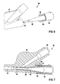
- FIGS. 4 to 7 a second embodiment of a connector 40 for a catheter according to the invention is shown, which is formed in two parts with a distal member 41 and a proximal member 42. Both elements 41, 42 are designed substantially hollow cylindrical.
- the distal member 41 has a through opening 43 into which the proximal end of the catheter shaft can be inserted.
- the proximal element 42 has a through opening 44 for the arrangement of the guide wire.
- a first conical section is provided on the outer side (shell) of the proximal element 42.
- the distal member 41 provides a sloped passage 46 for connection to a fluid source for inflation / deflation of a balloon, not shown, connected to the catheter shaft.
- the channel 46 extends into the through opening 43 of the distal element 41.
- the distal element 41 further has at its proximal end a slot-shaped blind hole 47 with an undercut for arranging a distally projecting from the proximal member 42 web 48 with a hook-shaped thickening at its distal end. Further, at the proximal end of the distal element 41 a rounded in cross-section guide groove 49 is provided, which in the assembly of the distal member 41 cooperates with proximal member 42 with a correspondingly shaped ridge 50 at the distal end of proximal member 42.
- the distal element 41 further has at its distal end a kink protection element 52 which is composed of adjacent annular elements, which are connected by means of longitudinally extending webs.
- a second conical section 55 is provided on the proximal element 42 in a central region with respect to the extension of the element in the longitudinal direction. Accordingly, the distal element also has a conical section 56 at its proximal end in the region of the inner wall.
- the proximal end of the catheter shaft is first pushed into the through hole 43 of the distal member 41.
- the insertion can be assisted by the guide wire.
- the annular elements and webs of the kink protection element 52 are arranged on the outside of the first tube 11.
- the proximal member 42 is inserted into the inner lumen of the second tube 12 so far that the second conical portion 55 of the proximal member 42 protrudes from the second tube.
- the first conical section at the distal end 45 of the proximal element 62 is arranged in the second tube 12.
- the distal member 41 is displaced in the proximal direction on the catheter shaft in the direction of the proximal member 42, wherein the web 48 is inserted into the blind hole 47 and the web 50 in the groove 49.
- the hook-shaped thickening of the web 48 engages behind the undercut of the blind hole 47 and thus causes a fastening of the proximal element 42 to the distal element 41 in the form of a snap connection.
- the second tube 12 is sealed at the same time.
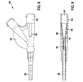
- FIGS. 8 to 15 A third embodiment of a connector 60 for a catheter according to the invention is shown, which is formed in two parts with a distal element 61 and a proximal element 62. Both elements 61, 62 are essentially analogous to the second embodiment according to FIG Fig. 4 to 7 and designed in a hollow cylindrical shape. The reference numerals of the elements 61, 62, which correspond to those of the second embodiment, refer to equal portions of the fitting.
- distal end 45 of the proximal member 62 is shaped slightly differently. It has several adjacent sections, which are partially conical.
Landscapes
- Health & Medical Sciences (AREA)
- Life Sciences & Earth Sciences (AREA)
- Heart & Thoracic Surgery (AREA)
- Biomedical Technology (AREA)
- Engineering & Computer Science (AREA)
- Anesthesiology (AREA)
- Pulmonology (AREA)
- Hematology (AREA)
- Animal Behavior & Ethology (AREA)
- General Health & Medical Sciences (AREA)
- Public Health (AREA)
- Veterinary Medicine (AREA)
- Biophysics (AREA)
- Media Introduction/Drainage Providing Device (AREA)
Abstract
Description
- Die vorliegende Erfindung betrifft ein Katheterschaft und einen Katheter sowie ein Verfahren zur Herstellung eines derartigen Katheterschafts bzw. Katheters.
- Katheter weisen im Bereich ihres Schafts Röhrchen oder Schläuche verschiedenen Durchmessers auf, die in den jeweiligen zu behandelnden Körperhohlraum eingeführt werden können. Sogenannte Ballonkatheter werden vor allem in der Angioplastie zur Erweiterung oder Wiedereröffnung eines Gefäßes eingesetzt (perkutane transluminale koronare Angioplastie - PTCA, auch percutaneous coronary intervention oder perkutane Koronarintervention - PCI). Ein solcher Ballonkatheter besitzt einen Schaft, der in einem vorgegebenen Bereich einen zunächst nicht dilatierten Ballon aufweist. Bei der Behandlung wird zuerst ein Führungsdraht in das zu behandelnde Gefäß eingeschoben. Anschließend wird der Schaft des Ballonkatheters entlang des Führungsdrahts bis zu der zu behandelnden Stelle des Gefäßes vorgeschoben, so dass der Ballon im Bereich der zu behandelnden Stelle des Gefäßes platziert ist, die z.B. eine Stenose aufweist. Danach wird der Ballon dilatiert, d.h. entfaltet und/oder aufgedehnt, so dass die zu behandelnde Stelle wiedereröffnet oder erweitert wird. Schließlich wird der Ballon entleert und entlang des Führungsdrahts wieder aus dem Gefäß entfernt. Gleichzeitig oder anschließend wird auch der Führungsdraht aus dem Gefäß zurückgezogen. Derartige Ballonkatheter können zusätzlich auch dazu verwendet werden, intraluminale Endoprothesen an eine zu behandelnde Stelle in einem Körperhohlraum einzubringen.
- Ein derartiger Katheter besitzt neben seinem Schaft in der Regel an seinem proximalen Ende ein Anschlussstück, welches zur Verbindung des Katheters mit der Kathetersteuerung und ggf. der Fluidversorgung dient. Das Anschlussstück ist mit dem Katheterschaft verbunden. Das distale Ende des Katheterschafts wird auch als Katheterspitze bezeichnet.
- Insbesondere für die Anwendung in der Angioplastie werden Katheter mit mehreren, insbesondere zwei Lumen verwendet, wobei z.B. das erste Lumen zur Aufnahme des Führungsdrahts und das zweite Lumen zur Durchleitung einer Flüssigkeit oder eines Gases dient. Für Katheter, die in der Hämolyse eingesetzt werden, kann das erste Lumen für die Entnahme von Blut aus dem Körper des Patienten und das zweite Lumen für die Rückführung des gereinigten Bluts eingesetzt werden. Ein derartiger Mehrlumenkatheter wird in der Druckschrift
WO 98/41277 A1 - Wie auch der Druckschrift
WO 98/41277 A1 US 6,248,092 B1 zeigt einen koaxialen Schaftaufbau. - Bei einem Zweilumenschlauch muss für die Anwendung im Bereich PTCA an dem Schaft ein Innenschlauch für das Ballonsegment und in vielen Fällen eine Führungsdrahtlumenverlängerung angebracht werden, um eine Durchgängigkeit des Führungsdrahtes durch den gesamten Katheter (vom Anschlussstück bis zur Katheterspitze) zu ermöglichen.
- Das Zweilumendesign hat zudem den Nachteil, dass in dem Bereich, in dem die Verlängerung an dem Schaft angebracht ist, kleinere Einschnürungen und Verhärtungen des Führungsdrahtlumens auftreten, welche die Push- und Trackability beeinflussen können. Zudem ist in diesem Bereich die Gefahr einer undichten Stelle gegeben. Da die Materialeigenschaften des Schafts alle Anforderungen des Systems erfüllen müssen, kann hierdurch oft nur ein Kompromiss zwischen Berstfestigkeit, FD-Reibung und Flexibilität hergestellt werden.
- Der herkömmliche koaxiale Schaftaufbau zeichnet sich in nachteiliger Weise dadurch aus, dass der Durchmesser des Schaftprofils vergleichsweise groß ist. Zudem verschlechtern sich bauartbedingt die Push-Eigenschaften an der Katheterspitze.
- Das konventionelle Koaxialdesign besitzt weiter den Nachteil, dass bei gleichen Abmessungen eine höhere Deflationszeit durch höhere Fluidreibung im Vergleich zum Zweilumendesign erreicht wird. Weiter kann es, da über einen Großteil des Schafts keine Verbindung von Innen- und Außenschlauch existiert, unter Belastung zu Relativbewegungen der ineinander verschachtelten zylindrischen Elemente kommen, welche die Track-/ Pusheigenschaften des Katheters negativ beeinflussen können.
- Die Aufgabe besteht daher darin, die oben diskutierten Eigenschaften des Katheters zu verbessern sowie ein kostengünstiges Verfahren für die Herstellung eines derartigen Katheters anzugeben.
- Die obige Aufgabe wird durch einen Katheterschaft gelöst, der einen ersten Schlauch, welcher ein erstes Lumen ausbildet, und einen zweiten Schlauch aufweist, welcher ein zweites Lumen ausbildet und zumindest teilweise innerhalb des ersten Schlauchs angeordnet ist. Hierbei ist der zweite Schlauch zumindest abschnittsweise mit seiner äußeren Oberfläche (Mantelfläche) mit der Innenfläche des ersten Schlauch verschweißt. Hierfür muss der Innendurchmesser des ersten Schlauchs größer sein als der Außendurchmesser des zweiten Schlauchs. Vorzugsweise bilden der Außendurchmesser des zweiten Schlauchs und der Innendurchmesser des ersten Schlauchs ein Verhältnis, das zwischen 0,4 und 0,95, besonders bevorzugt zwischen 0,6 und 0,9, liegt. D.h. der Außendurchmesser des zweiten, inneren Schlauchs beträgt mindestens das 0,4fache, bevorzugt das 0,6fache, des Innendurchmessers des ersten, äußeren Schlauchs und maximal das 0,95fache, bevorzugt das 0,9fache, des Innendurchmessers des ersten, äußeren Schlauchs.
- Das (innere) Lumen des ersten Schlauchs bildet vorzugsweise das Inflationslumen, während das (innere) Lumen des zweiten Schlauchs, d.h. das kleinere Lumen, vorzugsweise das Führungsdrahtlumen darstellt.
- Durch einen derartigen Aufbau eines Katheterschafts vereinfacht sich die Systemmontage, so dass die Kosten für die Herstellung eines Katheters reduziert und weniger Ausschuss produziert wird. Durch die Verwendung zweier ineinander angeordneter, aneinander befestigter Schläuche wird zudem die FD-Gängigkeit verbessert, da das Führungsdrahtlumen komplett homogen und rund ausgebildet ist. Im Vergleich zum herkömmlichen koaxialen Schaftaufbau ohne Verbindung von Innen- und Außenschlauch kann die Deflationszeit verringert und ein erhöhter Push erreicht werden.
- Bei dem erfindungsgemäßen Katheterschaft sind der erste Schlauch und der zweite Schlauch derart ineinander angeordnet, dass die Längsachsen der Schläuche, welche vorzugsweise jeweils einen kreisförmigen Querschnitt aufweisen, parallel zueinander verlaufen. Andere Querschnittsformen als die Kreisform für den ersten Schlauch und/oder den zweiten Schlauch sind ebenfalls denkbar (z.B. rechteckiger Querschnitt).
- In einem besonders bevorzugten Ausführungsbeispiel erstreckt sich die Schweißnaht parallel zur Längsachse des ersten Schlauchs und/oder des zweiten Schlauchs. Hierdurch werden Einschnürungen im Bereich des Schafts vermieden, so dass ebenfalls die Push- und Trackability-Eigenschaften verbessert werden.
- Es ist weiter von Vorteil, wenn der erste Schlauch zumindest im Bereich seiner inneren Oberfläche und/oder der zweite Schlauch zumindest im Bereich seiner äußeren Oberfläche (d.h. an seiner Mantelfläche) ein laseraktives Material aufweist. Ein derartiges laseraktives Material erwärmt sich bei Laserbestrahlung mit einer bestimmten Wellenlänge. Über diese Bereiche mit laseraktiven Materialien lassen sich dann der erste und der zweite Schlauch leicht verschweißen, so dass die Systemmontage weiter vereinfacht wird. Die verwendete Wellenlänge des Lasers ist materialabhängig und wird vorteilhafterweise entsprechend ausgewählt. Weiter lassen sich der erste Schlauch und der zweite Schlauch so verbinden, dass keine Deformation der Oberfläche der Schläuche entsteht, welche die Eigenschaften des Katheterschafts negativ beeinflussen kann.
- Nichtlaseraktive Materialien können durch Wärmestrahlung (z.B. mittels Schweißbacken, Heißluft oder Laser) verbunden werden.
- Der erfindungsgemäße Katheterschaft kann weiter dadurch verbessert werden, dass der erste Schlauch eine erste chemische Zusammensetzung und der zweite Schlauch eine zweite chemische Zusammensetzung aufweist, wobei die zweite chemische Zusammensetzung von der ersten chemischen Zusammensetzung verschieden ist. In einer vorteilhaften Ausgestaltung der Erfindung besteht der zweite Schlauch aus einem Polyamid, beispielsweise PA12. Polyamid gewährleistet eine geringe Reibung zwischen Führungsdraht und Schlauch. Der erste Schlauch besteht in dieser Ausgestaltung vorteilhafterweise aus einem thermoplastischen Copolyamid, beispielsweise PEBAX, wodurch insgesamt eine hohe Flexibilität des Kathetersystems erreicht wird. Durch diese erfindungsgemäße Lösung können die Materialien der Schläuche für den jeweiligen Einsatzzweck gemäß der jeweiligen Anforderungen (z.B. hinsichtlich Berstdruck Flexibilität, Beschichtung, FD-Reibung) optimiert und somit auch die Eigenschaften des Gesamtsystems verbessert werden.
- Vorteilhafterweise besteht der erste und/oder der zweite Schlauch aus mindestens einem Material ausgewählt aus der Gruppe enthaltend Polyamide, insbesondere PA12, thermoplastische Elastomere, insbesondere thermoplastische Copolyamide wie PEBAX 7033, PEBAX 7233, Grilamid L25 und Vestamid L2101.
- Die obige Aufgabe wird weiter durch einen Katheter mit einem Katheterschaft mit den oben angegebenen neuen Merkmalen gelöst. Hierdurch weist der erfindungsgemäße Katheter die oben angegebenen Vorteile auf.
- Der Schaft des erfindungsgemäßen Katheters ist in einem besonders bevorzugten Ausführungsbeispiel mit einem Anschlussstück verbunden, welches mindestens einen konischen Abschnitt aufweist, auf dem das proximale Ende des ersten Schlauchs oder des zweiten Schlauchs angeordnet ist. Der Konus ist hierbei derart beschaffen, dass der äußere Querschnitt des Abschnitts in proximaler Richtung zunimmt. Weiter weist der konische Abschnitt vorzugsweise eine innenliegende durchgehende Öffnung auf. Der Vorteil dieser Lösung besteht darin, dass der Schaftschlauch beim Aufstecken auf das Anschlussstück automatisch proximal abgedichtet wird. Hierdurch kann die Montage des Katheters weiter vereinfacht und eine besonders gute Abdichtung im Bereich des Abschlussstücks erreicht werden. Der konische Abschnitt ist vorzugsweise innerhalb eines im Wesentlichen hohlzylinderförmigen Körpers des Anschlussstücks an dessen proximalem Ende angeordnet.
- Durch den Konus wird das Lumen des Führungsdrahts, wenn der Schlauch des Führungsdrahts auf dem konischen Abschnitt des Anschlussstücks angeordnet ist, aufgeweitet. Neben dem dichten Abschluss wird ein sanfter Übergang von dem Schaftschlauch zum Anschlussstück realisiert, so dass eine Kante, an der der Führungsdraht hängen bleiben könnte, vermieden wird.
- In einem weiteren bevorzugten Ausführungsbeispiel kann das Anschlussstück mehrteilig ausgebildet sein, nämlich mit mindestens einem distalen Element und einem proximalen Element mit dem konischen Abschnitt, wobei das distale Element mit dem proximalen Element vorzugsweise mittels einer Schnappverbindung, einer Schweißverbindung oder einer anderen vorzugsweise nicht lösbaren Verbindung miteinander verbindbar sind. Durch die mehrteilige Ausbildung des Anschlussstücks kann eine sichere Befestigung des Katheterschafts erzielt werden, so dass auf eine Verklebung mit dem Katheterschaft verzichtet werden kann. Zusätzlich kann das distale Element an seinem distalen Ende eine Knickschutz-Einrichtung aufweisen. Diese besteht vorzugsweise aus ringförmigen Elementen, welche mittels in Längsrichtung (axiale Richtung) verlaufenden Stegen miteinander verbunden sind. Die Knickschutz-Einrichtung ist dabei derart dimensioniert, dass sie den ersten Schlauch des Katheterschafts nach der Montage des Anschlussstücks außen umgibt.
- In einer bevorzugten Ausführungsform der Ausgestaltung als mehrteiliges Anschlussstück wird das distale Element in einem Zweikomponentenspritzgussverfahren hergestellt. Die Knickschutz-Einrichtung besteht dabei aus einem weicheren und elastischeren Material als der Rest des distalen Elements. Durch die Verwendung eines weicheren Materials wird der Knickschutz effizienter und kann mit optionalen Dichtungen aus demselben Material besser abgedichtet werden. Die Haltekraft der Katheterschläuche am Anschlussstück wird dadurch ebenfalls erhöht. Auch für das proximale Element kann die Verwendung verschiedener Materialien vorteilhaft wirken. Wird hier für das konische, distale Ende des proximalen Elements ein weicheres und elastischeres Material verwendet, wird die Dichtigkeit verbessert und über die elastischen Eigenschaften eine Federwirkung erzielt. Diese Federwirkung hält den Druck bei einer Schnappverbindung über eine lange Zeit aufrecht.
- Als weicheres Material für die Knickschutz-Einrichtung wird vorzugsweise ein Polyether-Block-Amid (PEBA oder TPE-A, wie beispielsweise erhältlich unter den Handelsnamen PEBAX ®, Vestamid E®, Grilflex ®), ein thermoplastisches Elastomer (TPE), insbesondere ein Polyester-Elastomer (TPE-E, z.B. erhältlich unter dem Handelsnamen Hydrel ®) eingesetzt. Als weiteres Material für die übrigen Elemente des Anschlussstücks wird bevorzugt ein amorphes Polyamid (z.B. erhältlich unter den Handelsnamen Grilamid TR ®, Trogamid ®), ein Polycarbonat (PC) (beispielsweise erhältlich unter der Bezeichnung Makroion ®) oder ein Polyethylenterephthalate (PET) verwendet.
- Besonders bevorzugt kann insbesondere bei der einteiligen Ausführungsform des Anschlussstücks dieses zusätzlich an der Innenseite seines distalen Endes mit der Außenfläche des ersten Schlauchs verklebt sein, so dass ein Abrutschen des jeweiligen, auf dem konischen Abschnitt des Anschlussstücks angeordneten Schlauchs vom Konus verhindert wird.
- Die oben beschriebenen Lösungen mit dem konischen Abschnitt des Anschlussstücks ermöglichen zudem eine effektive Automatisierung des Fügeprozesses von Schaft und Anschlussstück.
- Für den Fall, dass gleichzeitig das Inflationslumen (z.B. erster Schlauch mit Lumen für ein Fluid, nicht für den Führungsdraht) durch die Ausweitung des Führungsdrahtlumens (z.B. zweiter Schlauch) verschlossen wird, kann ein zusätzlicher Schnitt am Inflationslumen Abhilfe schaffen. Dieser Schnitt könnte beispielsweise direkt beim Verbinden des Anschlussstücks mit dem proximalen Ende des Schafts erfolgen. Dafür wird im Inflationslumen eine Kunststoffklinge vorgesehen, welche den Schnitt bewirkt. Die Kunststoffklinge wird bevorzugt am Anschlussstück auf einer parallel zur Längsachse verlaufenden Nut oder Rippe angeordnet.
- Die obige Aufgabenstellung wird ferner durch ein Verfahren zur Herstellung eines Katheterschafts gelöst, welches die folgenden Schritte beinhaltet:
- Bereitstellung eines ersten Schlauchs und eines zweiten Schlauchs,
- Anordnen des zweiten Schlauchs zumindest teilweise in dem ersten Schlauch und
- Verschweißen des zweiten Schlauchs zumindest abschnittsweise mit seiner äußeren Oberfläche mit der Innenfläche des ersten Schlauchs.
- Hierbei werden der erste Schlauch und der zweite Schlauch derart ineinander angeordnet, dass die Längsachsen der beiden Schläuche, welche vorzugsweise jeweils einen kreisförmigen Querschnitt aufweisen, nach der Fertigstellung parallel zueinander verlaufen. Weiter erfolgt in einem besonders bevorzugten Ausführungsbeispiel das Verschweißen derart, dass sich die Schweißnaht parallel zur Längsachse des ersten Schlauchs und/oder des zweiten Schlauchs erstreckt.
- Das obige erfindungsgemäße Verfahren ist besonders einfach und kostengünstig durchführbar.
- Die obige Aufgabe wird ferner durch ein Verfahren zur Herstellung eines Katheters gelöst, bei dem die oben angegebenen Schritte zur Herstellung eines Katheterschafts durchgeführt werden sowie anschließend der zusätzliche Schritt, dass der Katheterschaft an seinem proximalen Ende mit einem einteiligen Anschlussstück oder einem mehrteiligen Anschlussstück mit mindestens einem distalen Element und einem proximalen Element verbunden wird.
- In einem besonders bevorzugten Ausführungsbeispiel wird hierbei das proximale Ende des Katheterschafts in den vorzugsweise hohlzylindrischen Körper des einteiligen Anschlussstücks eingeführt. Besonders bevorzugt wird dabei der erste Schlauch oder der zweite Schlauch über einem oben beschriebenen konischen Abschnitt des Anschlussstücks angeordnet, so dass automatisch eine Abdichtung des Schlauchs erfolgt. Hierbei wird das Lumen des entsprechenden Schlauchs in diesem Bereich aufgeweitet. Nach dem Einführen und Verbinden des Katheterschafts mit dem Anschlussstück wird vorzugsweise das Anschlussstück an der Innenseite des distalen Endes seines Körpers mit der Außenfläche des ersten Schlauchs und/oder des zweiten Schlauchs verklebt.
- Alternativ, bei der Verwendung eines mehrteiligen Anschlussstücks, wird das proximale Ende des Katherschafts in eine durchgehende Öffnung des distalen Elements eingefädelt, anschließend das proximale Element mit seinem konischen Abschnitt in das proximale Ende des Katheterschafts, vorzugsweise in das proximale Ende des zweiten Schlauchs, eingeführt und danach das distale Element in proximaler Richtung zum proximalen Element des Anschlussstücks verschoben und mit diesem, z.B. mittels einer Schnappverbindung, verbunden. Dies ist ein besonders einfaches und kostengünstiges Vorgehen zum Befestigen des Katheterschafts an dem Anschlussstück. Hierbei wird das proximale Ende des Katheterschafts beim Einfädeln in das distale Element auch durch eine durchgehende Öffnung der Knickschutz-Einrichtung hindurchgefädelt.
- Weitere Ziele, Merkmale, Vorteile und Anwendungsmöglichkeiten der Erfindung ergeben sich aus der nachfolgenden Beschreibung von Ausführungsbeispielen anhand der Figuren. Dabei bilden alle beschriebenen und/oder bildlich dargestellten Merkmale für sich oder in beliebiger Kombination den Gegenstand der vorliegenden Erfindung, auch unabhängig von ihrer Zusammenfassung in den einzelnen Ansprüchen oder deren Rückbeziehung.
- Es zeigen schematisch:
- Fig. 1
- einen erfindungsgemäßen Katheterschaft in einer Ansicht von der Seite,
- Fig. 2
- den erfindungsgemäßen Katheterschaft gemäß
Fig. 1 im Querschnitt und - Fig. 3
- einen Längsschnitt durch einen erfindungsgemäßen Katheter im Bereich eines ersten Ausführungsbeispiels eines Anschlussstücks,
- Fig. 4
- ein zweites Ausführungsbeispiel eines Anschlussstücks für einen erfindungsgemäßen Katheter mit einem distalen Element und einem mit dem distalen Element verbundenen proximalen Element in einer perspektivischen Ansicht von der Seite,
- Fig. 5
- das Ausführungsbeispiel des Anschlussstücks gemäß
Fig. 4 , wobei das distale Element und das proximale Element getrennt in einer perspektivischen Ansicht von hinten dargestellt sind, - Fig. 6
- eine weitere getrennte Darstellung des distalen Elements und des proximalen Elements des Ausführungsbeispiels eines Anschlussstücks gemäß
Fig. 4 in einer perspektivischen Ansicht von der Seite, - Fig. 7
- das Ausführungsbeispiel des Anschlussstücks gemäß
Fig. 4 mit verbundenem distalen Element und proximalen Element in einem Querschnitt, - Fig. 8
- ein drittes Ausführungsbeispiel eines Anschlussstücks für einen erfindungsgemäßen Katheter mit einem distalen Element und einem mit dem distalen Element verbundenen proximalen Element in einer perspektivischen Ansicht von der Seite,
- Fig. 9
- das Ausführungsbeispiel eines Anschlussstücks gemäß
Fig. 8 in einem Querschnitt, - Fig. 10
- der Querschnitt gemäß
Fig. 9 des Ausführungsbeispiels eines Anschlussstücks gemäßFig. 8 , wobei das distale Element und das proximale Element separat dargestellt sind, - Fig. 11
- eine weitere getrennte Darstellung des distalen Elements und des proximalen Elements des Ausführungsbeispiels gemäß
Fig. 8 in einer Ansicht von der Seite, - Fig. 12
- eine weitere getrennte Darstellung des distalen Elements und des proximalen Elements des Ausführungsbeispiels gemäß
Fig. 8 in einem Querschnitt, - Fig. 13
- das Ausführungsbeispiel eines Anschlussstücks gemäß
Fig. 8 in einem weiteren Querschnitt, - Fig. 14
- eine weitere getrennte Darstellung des distalen Elements und des proximalen Elements des Ausführungsbeispiels gemäß
Fig. 8 in einer perspektivischen Ansicht von der Seite und - Fig. 15
- eine weitere getrennte Darstellung des distalen Elements und des proximalen Elements des Ausführungsbeispiels gemäß
Fig. 8 geschnitten, in einer perspektivischen Ansicht von der Seite. - Die
Figuren 1 und 2 zeigen einen Katheterschaft 10 mit einem ersten Schlauch 11 und einem zweiten Schlauch 12, wobei der erste Schlauch 11 und der zweite Schlauch 12 parallel zu ihrer Längsachse ineinander angeordnet sind. Im Bereich seiner äußeren Oberfläche (Mantelfläche) ist der zweite Schlauch 12 mit dem ersten Schlauch 11, d.h. insbesondere mit seiner Innenfläche, entlang einer Schweißnaht 15 verschweißt. Die Schweißnaht 15 verläuft parallel zur Längsachse des ersten Schlauchs 11 beziehungsweise des zweiten Schlauchs 12, wobei die Schweißnaht 15 sich entweder über die gesamte Länge des Katheterschafts erstreckt oder abschnittsweise, wie inFigur 1 gezeigt, verläuft. - Um eine gute Verschweißung zwischen dem ersten Schlauch 11 und dem zweiten Schlauch 12 zu erreichen, weist der erste Schlauch 11 in dem Bereich seiner Innenfläche und/oder der zweite Schlauch 12 im Bereich seiner äußeren Mantelfläche ein laseraktives Material auf. Der erste Schlauch 11 kann beispielsweise aus PEBAX und der zweite Schlauch 12 aus PA12 bestehen. Das laseraktive Material ist bevorzugt auf der Mantelfläche des zweiten Schlauchs 12 aufgebracht.
- Der zweite Schlauch 12 kann beispielsweise zur Anordnung eines Führungsdrahts 23 dienen, während der erste Schlauch 11 das Inflationslumen ausbildet.
- Der in
Figur 3 gezeigt erfindungsgemäße Katheter besitzt ein Anschlussstück 20, welches mit dem proximalen Ende des Katheterschafts 10 verbunden ist. Der Körper des Anschlussstücks 20 ist an seinem distalen Ende 21 hohlzylinderförmig ausgebildet, so dass sowohl der erste Schlauch 11 als auch der zweite Schlauch 12 des Katheterschafts 10 in die Öffnung des Anschlussstücks 20 eingeführt werden können. An dem proximalen Ende des Anschlussstücks 20 ist zudem ein konischer Abschnitt 25 vorgesehen, auf den der zweite Schlauch 12 aufgeschoben wird, so dass dieser Schlauch 12 automatisch abgedichtet wird. Ferner weist das Anschlussstück 20 einen Kanal 26 auf, in den das Lumen des ersten Schlauchs 11 mündet und dieses mit einer Fluidquelle zur Inflation/Deflation eines Ballons verbindet. - Nachdem das proximale Ende des Katheterschafts 10 in das Anschlussstück 20 vollständig eingeführt wurde, wird im Bereich des distalen Endes 21 des Körpers des Anschlussstücks 20 die Außenfläche des ersten Schlauchs 11 und die Außenfläche des zweiten Schlauchs 12 mit der Innenfläche des Anschlussstücks mittels eines Klebstoffs 27 verklebt, so dass der erste Schlauch 11 nicht vom konischen Abschnitt 25 abrutscht.
- In den
Figuren 4 bis 7 ist ein zweites Ausführungsbeispiel eines Anschlussstücks 40 für einen erfindungsgemäßen Katheter gezeigt, das zweiteilig mit einem distalen Element 41 und einem proximalen Element 42 ausgebildet ist. Beide Elemente 41, 42 sind im Wesentlichen hohlzylinderförmig gestaltet. - Das distale Element 41 weist eine durchgehende Öffnung 43 auf, in die das proximale Ende des Katheterschafts eingeführt werden kann. Entsprechend besitzt das proximale Element 42 eine durchgehende Öffnung 44 zur Anordnung des Führungsdrahts. An seinem distalen Ende 45 ist an der Außenseite (Mantel) des proximalen Elements 42 ein erster konischer Abschnitt vorgesehen. Weiter sieht das distale Element 41 einen schräg verlaufenden Kanal 46 zur Verbindung mit einer Fluidquelle zur Inflation/Deflation eines an den Katheterschaft angeschlossenen, nicht dargestellten Ballons vor. Der Kanal 46 erstreckt sich bis in die durchgehende Öffnung 43 des distalen Elements 41.
- Das distale Element 41 besitzt weiter an seinem proximalen Ende ein schlitzförmiges Sackloch 47 mit einer Hinterschneidung zur Anordnung eines von dem proximalen Element 42 in distaler Richtung vorstehenden Stegs 48 mit einer hakenförmigen Verdickung an seinem distalen Ende. Weiter ist an dem proximalen Ende des distalen Elements 41 eine im Querschnitt gerundete Führungsnut 49 vorgesehen, welche beim Zusammenfügen des distalen Elements 41 mit dem proximalen Element 42 mit einem entsprechend geformten Steg 50 an dem distalen Ende des proximalen Elements 42 kooperiert.
- Das distale Element 41 weist ferner an seinem distalen Ende ein Knickschutzelement 52 auf, das aus nebeneinander liegenden ringförmigen Elementen zusammengesetzt ist, welche mittels in Längsrichtung verlaufenden Stegen verbunden sind.
- Weiter ist an dem proximalen Element 42 in einem mittigen Bereich in Bezug auf die Ausdehnung des Elements in Längsrichtung ein zweiter konischer Abschnitt 55 vorgesehen. Entsprechend weist das distale Element an seinem proximalen Ende im Bereich der Innenwand ebenfalls einen konischen Abschnitt 56 auf.
- Zur Herstellung des erfindungsgemäßen Katheters mittels eines oben beschriebenen Katheterschafts und des in den
Figuren 4 bis 7 dargestellten Anschlussstücks 40 wird zunächst das proximale Ende des Katheterschafts in die durchgehende Öffnung 43 des distalen Elements 41 hineingeschoben. Das Einschieben kann durch den Führungsdraht unterstützt werden. Danach sind die ringförmigen Elemente und Stege des Knickschutzelements 52 auf der Außenseite des ersten Schlauchs 11 angeordnet. - Anschließend wird das proximale Element 42 in das innere Lumen des zweiten Schlauchs 12 soweit eingeführt, dass der zweite konische Abschnitt 55 des proximalen Elements 42 aus dem zweiten Schlauch hervorschaut. Der erste konische Abschnitt an dem distalen Ende 45 des proximalen Elements 62 ist demgegenüber in dem zweiten Schlauch 12 angeordnet.
- Danach wird das distale Element 41 in proximale Richtung auf dem Katheterschaft in Richtung proximales Element 42 verschoben, wobei der Steg 48 in das Sackloch 47 und der Steg 50 in die Nut 49 eingeführt wird. Am Ende des Verschiebewegs hintergreift die hakenförmige Verdickung des Stegs 48 die Hinterschneidung des Sacklochs 47 und bewirkt somit eine Befestigung des proximalen Elements 42 an dem distalen Element 41 in Form einer Schnappverbindung. Durch den ersten konischen Abschnitt 45 wird gleichzeitig der zweite Schlauch 12 abgedichtet. Weiter bewirkt ein Formschluss zwischen dem zweiten konischen Abschnitt 55 des proximalen Elements 42 und dem konischen Abschnitt 56 des distalen Elements 41 eine Abdichtung des Inflationslumens des ersten Schlauchs 11.
- In den
Figuren 8 bis 15 ist ein drittes Ausführungsbeispiel eines Anschlussstücks 60 für einen erfindungsgemäßen Katheter gezeigt, das zweiteilig mit einem distalen Element 61 und einem proximalen Element 62 ausgebildet ist. Beide Elemente 61, 62 sind im Wesentlichen analog zu dem zweiten Ausführungsbeispiel gemäßFig. 4 bis 7 und hohlzylinderförmig gestaltet. Die Bezugszeichen der Elemente 61, 62, welche denen des zweiten Ausführungsbeispiels entsprechen, beziehen sich auf gleiche Bereiche des Anschlussstücks. - Bei dem dritten Ausführungsbeispiel eines Anschlussstücks erfolgt eine andere Befestigung des distalen Elements 61 an dem proximalen Element 62, nämlich mittels in distaler Richtung von dem proximalen Element 62 vorstehender zwei Stege 48 mit hakenförmiger Verdickung an seinem distalen Ende und entsprechend geformter Kerben (Ausnehmungen) 67, welche in der äußeren Oberfläche des distalen Elements 61 angebracht sind. Jede Kerbe weist eine Hinterschneidung auf, welche zur Anordnung der hakenförmigen Verdickung an dem distalen Ende des Stegs 48 dient. Hierdurch wird beim Befestigen des proximalen Elements ein Formschluss erzielt. Die Kerben 67 dienen gleichzeitig zur Führung der Stege 48. Daher ist bei dieser Ausführungsform kein zusätzlicher Führungssteg wie bei dem zweiten Ausführungsbeispiel erforderlich.
- Weiter ist das distale Ende 45 des proximalen Elements 62 etwas anders geformt. Es weist mehrere nebeneinander liegende Abschnitte auf, die teilweise konisch ausgebildet sind.
- Mit den in den
Figuren 4 bis 15 dargestellten mehrteiligen Anschlussstücken 40 und 60 wird eine einfache Montage des Katheters erreicht, welche eine sichere und fluiddichte Verbindung zwischen Katheterschaft und Anschlussstück bewirkt. -
- 10
- Katheterschaft
- 11
- erster Schlauch
- 12
- zweiter Schlauch
- 15
- Schweißnaht
- 20
- Anschlussstück
- 21
- distales Ende des Körpers des Anschlussstücks 20
- 23
- Führungsdraht
- 25
- konischer Abschnitt
- 26
- Kanal
- 27
- Klebstoff
- 40, 60
- Anschlussstück
- 41, 61
- distales Element
- 42, 62
- proximales Element
- 43
- durchgehende Öffnung
- 44
- durchgehende Öffnung
- 45
- distales Ende des proximalen Elements 42, 62
- 46
- Kanal zur Inflation/Deflation
- 47
- Sackloch
- 48
- Steg
- 49
- Nut
- 50
- Steg
- 52
- Knickschutz-Einrichtung
- 55
- zweiter konischer Abschnitt
- 56
- konischer Abschnitt
- 67
- Kerbe
Claims (13)
- Katheterschaft (10) aufweisend einen ersten Schlauch (11), welcher ein erstes Lumen ausbildet, und einen zweiten Schlauch (12), welcher ein zweites Lumen ausbildet und zumindest teilweise innerhalb des ersten Schlauchs (11) angeordnet ist, wobei der zweite Schlauch (12) zumindest abschnittsweise mit seiner äußeren Oberfläche mit der Innenfläche des ersten Schlauchs (11) verschweißt ist.
- Katheterschaft (10) nach Anspruch 1, dadurch gekennzeichnet, dass sich die Schweißnaht (15) parallel zur Längsachse des ersten Schlauchs (11) und/oder des zweiten Schlauchs (12) erstreckt.
- Katheterschaft (10) nach einem der vorhergehenden Ansprüche, dadurch gekennzeichnet, dass der erste Schlauch (11) zumindest im Bereich seiner inneren Oberfläche und/oder der zweite Schlauch (12) zumindest im Bereich seiner äußeren Oberfläche ein laseraktives Material aufweist.
- Katheterschaft (10) nach einem der vorhergehenden Ansprüche, dadurch gekennzeichnet, dass der erste Schlauch (11) eine erste chemische Zusammensetzung und der zweite Schlauch (12) eine zweite chemische Zusammensetzung aufweist, wobei die zweite chemische Zusammensetzung von der ersten chemischen Zusammensetzung verschieden ist.
- Katheter mit einem Katheterschaft (10) nach einem der vorhergehenden Ansprüche.
- Katheter nach Anspruch 5, dadurch gekennzeichnet, dass der Katheterschaft (10) mit einem Anschlussstück (20, 40) verbunden ist, welches mindestens einen konischen Abschnitt (25, 45) aufweist, auf dem das proximale Ende des ersten Schlauchs (11) oder des zweiten Schlauchs (12) angeordnet ist.
- Katheter nach einem der Ansprüche 5 oder 6, dadurch gekennzeichnet, dass das Anschlussstück (40, 60) mindestens ein distales Element (41, 61) und ein proximales Element (42, 62) mit dem konischen Abschnitt (45) aufweist, wobei das distale Element (41, 61) mit dem proximalen Element (42, 62) vorzugsweise mittels einer Schnappverbindung oder eine Schweißverbindung miteinander verbindbar sind.
- Katheter nach einem der Ansprüche 5 bis 7, dadurch gekennzeichnet, dass das distale Element (41, 61) an seinem distalen Ende eine Knickschutz-Einrichtung (52) aufweist.
- Katheter nach einem der Ansprüche 6 bis 8, dadurch gekennzeichnet, dass das Anschlussstück (20, 60) oder das distale Element (41, 61) des Anschlussstücks (40) an der Innenseite seines distalen Endes (21) mit der Außenfläche des ersten Schlauchs (11) verklebt ist.
- Verfahren zur Herstellung eines Katheterschafts (10), welches die folgenden Schritte beinhaltet:- Bereitstellung eines ersten Schlauchs (11) und eines zweiten Schlauchs (12),- Anordnen des zweiten Schlauchs (12) zumindest teilweise in dem ersten Schlauch (11) und- Verschweißen des zweiten Schlauch (12) zumindest abschnittsweise mit seiner äußeren Oberfläche mit der Innenfläche des ersten Schlauchs (11).
- Verfahren zur Herstellung eines Katheters, welches die in dem Anspruch 10 angegebenen Schritte aufweist sowie den zusätzlichen Schritt, dass der Katheterschaft (10) an seinem proximalen Ende• mit einem einteiligen Anschlussstück (20) oder• einem mehrteiligen Anschlussstück (40, 60) mit mindestens einem distalen Element (41, 61) und einem proximalen Element (42, 62)verbunden wird.
- Verfahren nach Anspruch 11, dadurch gekennzeichnet, dass das proximale Ende des Katherschafts (10) zum Verbinden mit dem einteiligen Anschlussstück (20) in das Anschlussstück (20) eingeführt und anschließend der erste Schlauch (11) oder der zweite Schlauch (12) über einem konischen Abschnitt (25) des einteiligen Anschlussstücks (20) angeordnet wird.
- Verfahren nach Anspruch 11, dadurch gekennzeichnet, dass zum Verbinden mit dem mehrteiligen Anschlussstück (40) das proximale Ende des Katherschafts (10) in das distale Element (41) eingefädelt, anschließend das proximale Element (42) mit seinem konischen Abschnitt (45) in das proximale Ende des Katheterschafts (10) eingeführt und danach das distale Element (41) in proximaler Richtung zum proximalen Element (42) verschoben und mit diesem, z.B. mittels einer Schnappverbindung, verbunden wird.
Priority Applications (1)
| Application Number | Priority Date | Filing Date | Title |
|---|---|---|---|
| EP19205810.5A EP3620200B1 (de) | 2014-08-14 | 2015-06-05 | Katheter |
Applications Claiming Priority (1)
| Application Number | Priority Date | Filing Date | Title |
|---|---|---|---|
| DE102014011948 | 2014-08-14 |
Related Child Applications (2)
| Application Number | Title | Priority Date | Filing Date |
|---|---|---|---|
| EP19205810.5A Division EP3620200B1 (de) | 2014-08-14 | 2015-06-05 | Katheter |
| EP19205810.5A Division-Into EP3620200B1 (de) | 2014-08-14 | 2015-06-05 | Katheter |
Publications (2)
| Publication Number | Publication Date |
|---|---|
| EP2985051A1 true EP2985051A1 (de) | 2016-02-17 |
| EP2985051B1 EP2985051B1 (de) | 2019-12-11 |
Family
ID=53284138
Family Applications (2)
| Application Number | Title | Priority Date | Filing Date |
|---|---|---|---|
| EP19205810.5A Active EP3620200B1 (de) | 2014-08-14 | 2015-06-05 | Katheter |
| EP15170754.4A Active EP2985051B1 (de) | 2014-08-14 | 2015-06-05 | Katheter sowie verfahren zur herstellung eines katheterschaftes |
Family Applications Before (1)
| Application Number | Title | Priority Date | Filing Date |
|---|---|---|---|
| EP19205810.5A Active EP3620200B1 (de) | 2014-08-14 | 2015-06-05 | Katheter |
Country Status (2)
| Country | Link |
|---|---|
| US (1) | US20160045708A1 (de) |
| EP (2) | EP3620200B1 (de) |
Families Citing this family (4)
| Publication number | Priority date | Publication date | Assignee | Title |
|---|---|---|---|---|
| JP6775351B2 (ja) * | 2016-08-18 | 2020-10-28 | テルモ株式会社 | 医療用デバイス |
| US11272946B2 (en) * | 2018-03-09 | 2022-03-15 | Acclarent, Inc. | Fluid fitting for dilation instrument |
| US11813417B2 (en) * | 2019-08-13 | 2023-11-14 | Medtronic Vascular, Inc. | Catheter modification device |
| CN111840759B (zh) * | 2020-07-28 | 2025-07-04 | 夏铁铮 | 一种医用导管 |
Citations (7)
| Publication number | Priority date | Publication date | Assignee | Title |
|---|---|---|---|---|
| EP0227230A1 (de) * | 1985-10-17 | 1987-07-01 | Menlo Care, Inc. | Kathetereinheit |
| WO1998041277A1 (en) | 1997-03-19 | 1998-09-24 | Microvena Corporation | Improved multi-lumen catheter |
| US6248092B1 (en) | 1994-06-24 | 2001-06-19 | Advanced Cardiovascular Systems, Inc. | Catheters having a reusable proximal body |
| US20030163082A1 (en) * | 2002-02-26 | 2003-08-28 | Mertens Steven P. | Lumen weld |
| US20040004311A1 (en) * | 2002-02-26 | 2004-01-08 | Scimed Life Systems, Inc. | Tacking method and apparatus |
| US20050059958A1 (en) * | 2003-09-11 | 2005-03-17 | Cook Incorporated | Catheter having an overmolded hub |
| US20070078439A1 (en) * | 2004-05-27 | 2007-04-05 | Axel Grandt | Multiple lumen catheter and method of making same |
Family Cites Families (8)
| Publication number | Priority date | Publication date | Assignee | Title |
|---|---|---|---|---|
| US5478331A (en) * | 1994-05-11 | 1995-12-26 | Localmed, Inc. | Multi-function proximal end adapter for catheter |
| US6273404B1 (en) * | 1995-06-05 | 2001-08-14 | Scimed Life Systems, Inc. | Method of making monolithic hub and strain relief |
| US7862541B2 (en) * | 2000-05-22 | 2011-01-04 | Abbott Laboratories Vascular Enterprises Limited | Catheter having a soft distal tip |
| US7037291B2 (en) * | 2001-12-04 | 2006-05-02 | Advanced Cardiovascular Systems, Inc. | Catheter shaft junction having a polymeric reinforcing member with a high glass transition temperature |
| US6802836B2 (en) * | 2002-02-19 | 2004-10-12 | Scimed Life Systems, Inc. | Low profile adaptor for use with a medical catheter |
| US9017308B2 (en) * | 2002-05-21 | 2015-04-28 | Boston Scientific Scimed, Inc. | Insert molded hub and strain relief |
| US7575568B2 (en) * | 2003-12-10 | 2009-08-18 | Boston Scientific Scimed, Inc. | Catheter distal tip |
| US9352118B2 (en) * | 2005-06-30 | 2016-05-31 | Abbott Laboratories | Modular introducer and exchange sheath |
-
2015
- 2015-06-05 EP EP19205810.5A patent/EP3620200B1/de active Active
- 2015-06-05 EP EP15170754.4A patent/EP2985051B1/de active Active
- 2015-07-28 US US14/810,806 patent/US20160045708A1/en not_active Abandoned
Patent Citations (7)
| Publication number | Priority date | Publication date | Assignee | Title |
|---|---|---|---|---|
| EP0227230A1 (de) * | 1985-10-17 | 1987-07-01 | Menlo Care, Inc. | Kathetereinheit |
| US6248092B1 (en) | 1994-06-24 | 2001-06-19 | Advanced Cardiovascular Systems, Inc. | Catheters having a reusable proximal body |
| WO1998041277A1 (en) | 1997-03-19 | 1998-09-24 | Microvena Corporation | Improved multi-lumen catheter |
| US20030163082A1 (en) * | 2002-02-26 | 2003-08-28 | Mertens Steven P. | Lumen weld |
| US20040004311A1 (en) * | 2002-02-26 | 2004-01-08 | Scimed Life Systems, Inc. | Tacking method and apparatus |
| US20050059958A1 (en) * | 2003-09-11 | 2005-03-17 | Cook Incorporated | Catheter having an overmolded hub |
| US20070078439A1 (en) * | 2004-05-27 | 2007-04-05 | Axel Grandt | Multiple lumen catheter and method of making same |
Also Published As
| Publication number | Publication date |
|---|---|
| EP3620200B1 (de) | 2023-07-26 |
| EP3620200A1 (de) | 2020-03-11 |
| US20160045708A1 (en) | 2016-02-18 |
| EP2985051B1 (de) | 2019-12-11 |
Similar Documents
| Publication | Publication Date | Title |
|---|---|---|
| DE4411707B4 (de) | Über-den-Draht-Katheter und Verfahren zur Herstellung eines solchen Katheters | |
| DE69531101T2 (de) | Verstärkter schnell austauschbarer ballonkatheter | |
| DE69312298T4 (de) | Dilatationskatheter mit versteifungsdraht | |
| DE69219878T2 (de) | Vorrichtung zur Aufweiten einer Stenose | |
| DE69304306T2 (de) | Dilatationskatheter | |
| DE69501822T2 (de) | Dilatationskatheter zum schnellen auswechseln | |
| DE4406077B4 (de) | Ballonkatheter- und Führungsdraht-Anordnung | |
| DE68919996T2 (de) | Katheter mit ausdehnbarem Element und dessen Herstellungsverfahren. | |
| DE69525351T2 (de) | Weiche, flexible katheterspitze zur anwendung in der angiographie | |
| EP0470925B1 (de) | Dilatationskatheter | |
| EP3470105B1 (de) | Einführelement für eine medizinische einführeinrichtung | |
| DE69509797T2 (de) | Vorrichtung zum auftragen einer oder mehrerer flüssigkeiten | |
| DE69401007T2 (de) | Aus Katheter und Hülse bestehende Einheit | |
| EP2988049B1 (de) | Verfahren zum verbinden von kunststoffröhrchen | |
| DE69322224T2 (de) | Dilatationskatheter mit geringem querschnitt | |
| EP1070513A1 (de) | Ballonkatheter für Gefässabzweigungen | |
| DE69322008T2 (de) | Intravaskulärer katheter mit einem distalen führungsdrahtlumen | |
| DE602004000415T3 (de) | Ballonkatheter mit selbstzentrierender Spitze | |
| EP2985051B1 (de) | Katheter sowie verfahren zur herstellung eines katheterschaftes | |
| DE202006020982U1 (de) | Katheter mit einer weichen distalen Spitze | |
| EP2524711B1 (de) | Verbindungssystem zur Herstellung eines Verbindungskanals für Körperflüssigkeiten | |
| DE102008040914A1 (de) | Ballonkatheter und Verfahren zu dessen Herstellung | |
| DE19526784A1 (de) | Doppelballonkatheter | |
| DE60116125T2 (de) | Kerndrahtbefestigungssystem | |
| EP2736586B1 (de) | Medizinischer schlauch sowie verfahren zum sterilisieren eines medizinischen schlauchs |
Legal Events
| Date | Code | Title | Description |
|---|---|---|---|
| PUAI | Public reference made under article 153(3) epc to a published international application that has entered the european phase |
Free format text: ORIGINAL CODE: 0009012 |
|
| AK | Designated contracting states |
Kind code of ref document: A1 Designated state(s): AL AT BE BG CH CY CZ DE DK EE ES FI FR GB GR HR HU IE IS IT LI LT LU LV MC MK MT NL NO PL PT RO RS SE SI SK SM TR |
|
| AX | Request for extension of the european patent |
Extension state: BA ME |
|
| 17P | Request for examination filed |
Effective date: 20160811 |
|
| RBV | Designated contracting states (corrected) |
Designated state(s): AL AT BE BG CH CY CZ DE DK EE ES FI FR GB GR HR HU IE IS IT LI LT LU LV MC MK MT NL NO PL PT RO RS SE SI SK SM TR |
|
| GRAP | Despatch of communication of intention to grant a patent |
Free format text: ORIGINAL CODE: EPIDOSNIGR1 |
|
| STAA | Information on the status of an ep patent application or granted ep patent |
Free format text: STATUS: GRANT OF PATENT IS INTENDED |
|
| RIC1 | Information provided on ipc code assigned before grant |
Ipc: B29L 31/00 20060101ALI20190708BHEP Ipc: A61M 25/09 20060101ALI20190708BHEP Ipc: A61M 39/10 20060101ALI20190708BHEP Ipc: A61M 25/00 20060101AFI20190708BHEP Ipc: A61M 25/10 20130101ALI20190708BHEP Ipc: B29C 65/00 20060101ALI20190708BHEP Ipc: B29C 65/16 20060101ALI20190708BHEP |
|
| INTG | Intention to grant announced |
Effective date: 20190807 |
|
| GRAS | Grant fee paid |
Free format text: ORIGINAL CODE: EPIDOSNIGR3 |
|
| GRAA | (expected) grant |
Free format text: ORIGINAL CODE: 0009210 |
|
| STAA | Information on the status of an ep patent application or granted ep patent |
Free format text: STATUS: THE PATENT HAS BEEN GRANTED |
|
| AK | Designated contracting states |
Kind code of ref document: B1 Designated state(s): AL AT BE BG CH CY CZ DE DK EE ES FI FR GB GR HR HU IE IS IT LI LT LU LV MC MK MT NL NO PL PT RO RS SE SI SK SM TR |
|
| REG | Reference to a national code |
Ref country code: GB Ref legal event code: FG4D Free format text: NOT ENGLISH |
|
| REG | Reference to a national code |
Ref country code: CH Ref legal event code: EP |
|
| REG | Reference to a national code |
Ref country code: AT Ref legal event code: REF Ref document number: 1211569 Country of ref document: AT Kind code of ref document: T Effective date: 20191215 |
|
| REG | Reference to a national code |
Ref country code: DE Ref legal event code: R096 Ref document number: 502015011176 Country of ref document: DE |
|
| REG | Reference to a national code |
Ref country code: IE Ref legal event code: FG4D Free format text: LANGUAGE OF EP DOCUMENT: GERMAN |
|
| REG | Reference to a national code |
Ref country code: NL Ref legal event code: FP |
|
| REG | Reference to a national code |
Ref country code: LT Ref legal event code: MG4D |
|
| PG25 | Lapsed in a contracting state [announced via postgrant information from national office to epo] |
Ref country code: LT Free format text: LAPSE BECAUSE OF FAILURE TO SUBMIT A TRANSLATION OF THE DESCRIPTION OR TO PAY THE FEE WITHIN THE PRESCRIBED TIME-LIMIT Effective date: 20191211 Ref country code: GR Free format text: LAPSE BECAUSE OF FAILURE TO SUBMIT A TRANSLATION OF THE DESCRIPTION OR TO PAY THE FEE WITHIN THE PRESCRIBED TIME-LIMIT Effective date: 20200312 Ref country code: NO Free format text: LAPSE BECAUSE OF FAILURE TO SUBMIT A TRANSLATION OF THE DESCRIPTION OR TO PAY THE FEE WITHIN THE PRESCRIBED TIME-LIMIT Effective date: 20200311 Ref country code: LV Free format text: LAPSE BECAUSE OF FAILURE TO SUBMIT A TRANSLATION OF THE DESCRIPTION OR TO PAY THE FEE WITHIN THE PRESCRIBED TIME-LIMIT Effective date: 20191211 Ref country code: SE Free format text: LAPSE BECAUSE OF FAILURE TO SUBMIT A TRANSLATION OF THE DESCRIPTION OR TO PAY THE FEE WITHIN THE PRESCRIBED TIME-LIMIT Effective date: 20191211 Ref country code: FI Free format text: LAPSE BECAUSE OF FAILURE TO SUBMIT A TRANSLATION OF THE DESCRIPTION OR TO PAY THE FEE WITHIN THE PRESCRIBED TIME-LIMIT Effective date: 20191211 Ref country code: BG Free format text: LAPSE BECAUSE OF FAILURE TO SUBMIT A TRANSLATION OF THE DESCRIPTION OR TO PAY THE FEE WITHIN THE PRESCRIBED TIME-LIMIT Effective date: 20200311 |
|
| PG25 | Lapsed in a contracting state [announced via postgrant information from national office to epo] |
Ref country code: RS Free format text: LAPSE BECAUSE OF FAILURE TO SUBMIT A TRANSLATION OF THE DESCRIPTION OR TO PAY THE FEE WITHIN THE PRESCRIBED TIME-LIMIT Effective date: 20191211 Ref country code: HR Free format text: LAPSE BECAUSE OF FAILURE TO SUBMIT A TRANSLATION OF THE DESCRIPTION OR TO PAY THE FEE WITHIN THE PRESCRIBED TIME-LIMIT Effective date: 20191211 |
|
| PG25 | Lapsed in a contracting state [announced via postgrant information from national office to epo] |
Ref country code: AL Free format text: LAPSE BECAUSE OF FAILURE TO SUBMIT A TRANSLATION OF THE DESCRIPTION OR TO PAY THE FEE WITHIN THE PRESCRIBED TIME-LIMIT Effective date: 20191211 |
|
| PG25 | Lapsed in a contracting state [announced via postgrant information from national office to epo] |
Ref country code: PT Free format text: LAPSE BECAUSE OF FAILURE TO SUBMIT A TRANSLATION OF THE DESCRIPTION OR TO PAY THE FEE WITHIN THE PRESCRIBED TIME-LIMIT Effective date: 20200506 Ref country code: CZ Free format text: LAPSE BECAUSE OF FAILURE TO SUBMIT A TRANSLATION OF THE DESCRIPTION OR TO PAY THE FEE WITHIN THE PRESCRIBED TIME-LIMIT Effective date: 20191211 Ref country code: RO Free format text: LAPSE BECAUSE OF FAILURE TO SUBMIT A TRANSLATION OF THE DESCRIPTION OR TO PAY THE FEE WITHIN THE PRESCRIBED TIME-LIMIT Effective date: 20191211 Ref country code: ES Free format text: LAPSE BECAUSE OF FAILURE TO SUBMIT A TRANSLATION OF THE DESCRIPTION OR TO PAY THE FEE WITHIN THE PRESCRIBED TIME-LIMIT Effective date: 20191211 Ref country code: EE Free format text: LAPSE BECAUSE OF FAILURE TO SUBMIT A TRANSLATION OF THE DESCRIPTION OR TO PAY THE FEE WITHIN THE PRESCRIBED TIME-LIMIT Effective date: 20191211 |
|
| PG25 | Lapsed in a contracting state [announced via postgrant information from national office to epo] |
Ref country code: SK Free format text: LAPSE BECAUSE OF FAILURE TO SUBMIT A TRANSLATION OF THE DESCRIPTION OR TO PAY THE FEE WITHIN THE PRESCRIBED TIME-LIMIT Effective date: 20191211 Ref country code: IS Free format text: LAPSE BECAUSE OF FAILURE TO SUBMIT A TRANSLATION OF THE DESCRIPTION OR TO PAY THE FEE WITHIN THE PRESCRIBED TIME-LIMIT Effective date: 20200411 Ref country code: SM Free format text: LAPSE BECAUSE OF FAILURE TO SUBMIT A TRANSLATION OF THE DESCRIPTION OR TO PAY THE FEE WITHIN THE PRESCRIBED TIME-LIMIT Effective date: 20191211 |
|
| REG | Reference to a national code |
Ref country code: DE Ref legal event code: R097 Ref document number: 502015011176 Country of ref document: DE |
|
| PLBE | No opposition filed within time limit |
Free format text: ORIGINAL CODE: 0009261 |
|
| STAA | Information on the status of an ep patent application or granted ep patent |
Free format text: STATUS: NO OPPOSITION FILED WITHIN TIME LIMIT |
|
| PG25 | Lapsed in a contracting state [announced via postgrant information from national office to epo] |
Ref country code: DK Free format text: LAPSE BECAUSE OF FAILURE TO SUBMIT A TRANSLATION OF THE DESCRIPTION OR TO PAY THE FEE WITHIN THE PRESCRIBED TIME-LIMIT Effective date: 20191211 |
|
| 26N | No opposition filed |
Effective date: 20200914 |
|
| PG25 | Lapsed in a contracting state [announced via postgrant information from national office to epo] |
Ref country code: SI Free format text: LAPSE BECAUSE OF FAILURE TO SUBMIT A TRANSLATION OF THE DESCRIPTION OR TO PAY THE FEE WITHIN THE PRESCRIBED TIME-LIMIT Effective date: 20191211 |
|
| PG25 | Lapsed in a contracting state [announced via postgrant information from national office to epo] |
Ref country code: MC Free format text: LAPSE BECAUSE OF FAILURE TO SUBMIT A TRANSLATION OF THE DESCRIPTION OR TO PAY THE FEE WITHIN THE PRESCRIBED TIME-LIMIT Effective date: 20191211 Ref country code: IT Free format text: LAPSE BECAUSE OF FAILURE TO SUBMIT A TRANSLATION OF THE DESCRIPTION OR TO PAY THE FEE WITHIN THE PRESCRIBED TIME-LIMIT Effective date: 20191211 |
|
| PG25 | Lapsed in a contracting state [announced via postgrant information from national office to epo] |
Ref country code: PL Free format text: LAPSE BECAUSE OF FAILURE TO SUBMIT A TRANSLATION OF THE DESCRIPTION OR TO PAY THE FEE WITHIN THE PRESCRIBED TIME-LIMIT Effective date: 20191211 |
|
| GBPC | Gb: european patent ceased through non-payment of renewal fee |
Effective date: 20200605 |
|
| PG25 | Lapsed in a contracting state [announced via postgrant information from national office to epo] |
Ref country code: LU Free format text: LAPSE BECAUSE OF NON-PAYMENT OF DUE FEES Effective date: 20200605 |
|
| REG | Reference to a national code |
Ref country code: BE Ref legal event code: MM Effective date: 20200630 |
|
| PG25 | Lapsed in a contracting state [announced via postgrant information from national office to epo] |
Ref country code: GB Free format text: LAPSE BECAUSE OF NON-PAYMENT OF DUE FEES Effective date: 20200605 |
|
| PG25 | Lapsed in a contracting state [announced via postgrant information from national office to epo] |
Ref country code: BE Free format text: LAPSE BECAUSE OF NON-PAYMENT OF DUE FEES Effective date: 20200630 |
|
| REG | Reference to a national code |
Ref country code: AT Ref legal event code: MM01 Ref document number: 1211569 Country of ref document: AT Kind code of ref document: T Effective date: 20200605 |
|
| PG25 | Lapsed in a contracting state [announced via postgrant information from national office to epo] |
Ref country code: AT Free format text: LAPSE BECAUSE OF NON-PAYMENT OF DUE FEES Effective date: 20200605 |
|
| PG25 | Lapsed in a contracting state [announced via postgrant information from national office to epo] |
Ref country code: TR Free format text: LAPSE BECAUSE OF FAILURE TO SUBMIT A TRANSLATION OF THE DESCRIPTION OR TO PAY THE FEE WITHIN THE PRESCRIBED TIME-LIMIT Effective date: 20191211 Ref country code: MT Free format text: LAPSE BECAUSE OF FAILURE TO SUBMIT A TRANSLATION OF THE DESCRIPTION OR TO PAY THE FEE WITHIN THE PRESCRIBED TIME-LIMIT Effective date: 20191211 Ref country code: CY Free format text: LAPSE BECAUSE OF FAILURE TO SUBMIT A TRANSLATION OF THE DESCRIPTION OR TO PAY THE FEE WITHIN THE PRESCRIBED TIME-LIMIT Effective date: 20191211 |
|
| PG25 | Lapsed in a contracting state [announced via postgrant information from national office to epo] |
Ref country code: MK Free format text: LAPSE BECAUSE OF FAILURE TO SUBMIT A TRANSLATION OF THE DESCRIPTION OR TO PAY THE FEE WITHIN THE PRESCRIBED TIME-LIMIT Effective date: 20191211 |
|
| PGFP | Annual fee paid to national office [announced via postgrant information from national office to epo] |
Ref country code: NL Payment date: 20220621 Year of fee payment: 8 Ref country code: IE Payment date: 20220616 Year of fee payment: 8 |
|
| P01 | Opt-out of the competence of the unified patent court (upc) registered |
Effective date: 20230613 |
|
| REG | Reference to a national code |
Ref country code: NL Ref legal event code: MM Effective date: 20230701 |
|
| REG | Reference to a national code |
Ref country code: IE Ref legal event code: MM4A |
|
| PG25 | Lapsed in a contracting state [announced via postgrant information from national office to epo] |
Ref country code: NL Free format text: LAPSE BECAUSE OF NON-PAYMENT OF DUE FEES Effective date: 20230701 |
|
| PG25 | Lapsed in a contracting state [announced via postgrant information from national office to epo] |
Ref country code: IE Free format text: LAPSE BECAUSE OF NON-PAYMENT OF DUE FEES Effective date: 20230605 |
|
| PG25 | Lapsed in a contracting state [announced via postgrant information from national office to epo] |
Ref country code: IE Free format text: LAPSE BECAUSE OF NON-PAYMENT OF DUE FEES Effective date: 20230605 |
|
| REG | Reference to a national code |
Ref country code: DE Ref legal event code: R082 Ref document number: 502015011176 Country of ref document: DE Representative=s name: WSL PATENTANWAELTE PARTNERSCHAFT MBB, DE |
|
| PGFP | Annual fee paid to national office [announced via postgrant information from national office to epo] |
Ref country code: CH Payment date: 20250701 Year of fee payment: 11 |
|
| REG | Reference to a national code |
Ref country code: CH Ref legal event code: U11 Free format text: ST27 STATUS EVENT CODE: U-0-0-U10-U11 (AS PROVIDED BY THE NATIONAL OFFICE) Effective date: 20260701 |
|
| PGFP | Annual fee paid to national office [announced via postgrant information from national office to epo] |
Ref country code: DE Payment date: 20260615 Year of fee payment: 12 |
|
| PGFP | Annual fee paid to national office [announced via postgrant information from national office to epo] |
Ref country code: FR Payment date: 20260626 Year of fee payment: 12 |