EP2984459B1 - Procédé et agencement pour introduire un matériau d'alimentation à partir d'un silo pour matériau d'alimentation dans un espace de four d'un four de fusion - Google Patents
Procédé et agencement pour introduire un matériau d'alimentation à partir d'un silo pour matériau d'alimentation dans un espace de four d'un four de fusion Download PDFInfo
- Publication number
- EP2984459B1 EP2984459B1 EP14782335.5A EP14782335A EP2984459B1 EP 2984459 B1 EP2984459 B1 EP 2984459B1 EP 14782335 A EP14782335 A EP 14782335A EP 2984459 B1 EP2984459 B1 EP 2984459B1
- Authority
- EP
- European Patent Office
- Prior art keywords
- fine
- grained matter
- feeding
- feed
- matter
- Prior art date
- Legal status (The legal status is an assumption and is not a legal conclusion. Google has not performed a legal analysis and makes no representation as to the accuracy of the status listed.)
- Active
Links
- 239000000463 material Substances 0.000 title claims description 140
- 238000003723 Smelting Methods 0.000 title claims description 58
- 238000000034 method Methods 0.000 title claims description 58
- 239000012141 concentrate Substances 0.000 claims description 109
- 238000004891 communication Methods 0.000 claims description 50
- 239000000725 suspension Substances 0.000 claims description 42
- 239000007787 solid Substances 0.000 claims description 16
- 238000005192 partition Methods 0.000 claims description 10
- 239000012495 reaction gas Substances 0.000 claims description 6
- 230000001276 controlling effect Effects 0.000 description 49
- 238000005243 fluidization Methods 0.000 description 26
- VYPSYNLAJGMNEJ-UHFFFAOYSA-N Silicium dioxide Chemical compound O=[Si]=O VYPSYNLAJGMNEJ-UHFFFAOYSA-N 0.000 description 12
- 239000000203 mixture Substances 0.000 description 12
- 230000009286 beneficial effect Effects 0.000 description 9
- 230000001105 regulatory effect Effects 0.000 description 9
- 235000008733 Citrus aurantifolia Nutrition 0.000 description 6
- 235000019738 Limestone Nutrition 0.000 description 6
- 235000011941 Tilia x europaea Nutrition 0.000 description 6
- 239000002826 coolant Substances 0.000 description 6
- 239000000428 dust Substances 0.000 description 6
- 239000010792 electronic scrap Substances 0.000 description 6
- 239000004571 lime Substances 0.000 description 6
- 239000006028 limestone Substances 0.000 description 6
- 239000000377 silicon dioxide Substances 0.000 description 6
- 239000002893 slag Substances 0.000 description 6
- 238000003325 tomography Methods 0.000 description 6
- 239000003245 coal Substances 0.000 description 4
- 239000007789 gas Substances 0.000 description 4
- 230000001419 dependent effect Effects 0.000 description 2
- 238000005259 measurement Methods 0.000 description 2
- RYGMFSIKBFXOCR-UHFFFAOYSA-N Copper Chemical compound [Cu] RYGMFSIKBFXOCR-UHFFFAOYSA-N 0.000 description 1
- 238000004590 computer program Methods 0.000 description 1
- 239000010949 copper Substances 0.000 description 1
- 229910052802 copper Inorganic materials 0.000 description 1
- OMZSGWSJDCOLKM-UHFFFAOYSA-N copper(II) sulfide Chemical compound [S-2].[Cu+2] OMZSGWSJDCOLKM-UHFFFAOYSA-N 0.000 description 1
- 230000004907 flux Effects 0.000 description 1
- 239000008187 granular material Substances 0.000 description 1
- 238000011144 upstream manufacturing Methods 0.000 description 1
- 238000012800 visualization Methods 0.000 description 1
Images


Classifications
-
- G—PHYSICS
- G01—MEASURING; TESTING
- G01F—MEASURING VOLUME, VOLUME FLOW, MASS FLOW OR LIQUID LEVEL; METERING BY VOLUME
- G01F1/00—Measuring the volume flow or mass flow of fluid or fluent solid material wherein the fluid passes through a meter in a continuous flow
- G01F1/76—Devices for measuring mass flow of a fluid or a fluent solid material
-
- F—MECHANICAL ENGINEERING; LIGHTING; HEATING; WEAPONS; BLASTING
- F27—FURNACES; KILNS; OVENS; RETORTS
- F27D—DETAILS OR ACCESSORIES OF FURNACES, KILNS, OVENS, OR RETORTS, IN SO FAR AS THEY ARE OF KINDS OCCURRING IN MORE THAN ONE KIND OF FURNACE
- F27D3/00—Charging; Discharging; Manipulation of charge
- F27D3/0033—Charging; Discharging; Manipulation of charge charging of particulate material
-
- C—CHEMISTRY; METALLURGY
- C22—METALLURGY; FERROUS OR NON-FERROUS ALLOYS; TREATMENT OF ALLOYS OR NON-FERROUS METALS
- C22B—PRODUCTION AND REFINING OF METALS; PRETREATMENT OF RAW MATERIALS
- C22B5/00—General methods of reducing to metals
- C22B5/02—Dry methods smelting of sulfides or formation of mattes
-
- F—MECHANICAL ENGINEERING; LIGHTING; HEATING; WEAPONS; BLASTING
- F27—FURNACES; KILNS; OVENS; RETORTS
- F27B—FURNACES, KILNS, OVENS, OR RETORTS IN GENERAL; OPEN SINTERING OR LIKE APPARATUS
- F27B1/00—Shaft or like vertical or substantially vertical furnaces
- F27B1/10—Details, accessories, or equipment peculiar to furnaces of these types
- F27B1/20—Arrangements of devices for charging
-
- F—MECHANICAL ENGINEERING; LIGHTING; HEATING; WEAPONS; BLASTING
- F27—FURNACES; KILNS; OVENS; RETORTS
- F27D—DETAILS OR ACCESSORIES OF FURNACES, KILNS, OVENS, OR RETORTS, IN SO FAR AS THEY ARE OF KINDS OCCURRING IN MORE THAN ONE KIND OF FURNACE
- F27D19/00—Arrangements of controlling devices
-
- F—MECHANICAL ENGINEERING; LIGHTING; HEATING; WEAPONS; BLASTING
- F27—FURNACES; KILNS; OVENS; RETORTS
- F27D—DETAILS OR ACCESSORIES OF FURNACES, KILNS, OVENS, OR RETORTS, IN SO FAR AS THEY ARE OF KINDS OCCURRING IN MORE THAN ONE KIND OF FURNACE
- F27D3/00—Charging; Discharging; Manipulation of charge
- F27D3/08—Screw feeders; Screw dischargers
-
- F—MECHANICAL ENGINEERING; LIGHTING; HEATING; WEAPONS; BLASTING
- F27—FURNACES; KILNS; OVENS; RETORTS
- F27D—DETAILS OR ACCESSORIES OF FURNACES, KILNS, OVENS, OR RETORTS, IN SO FAR AS THEY ARE OF KINDS OCCURRING IN MORE THAN ONE KIND OF FURNACE
- F27D3/00—Charging; Discharging; Manipulation of charge
- F27D3/10—Charging directly from hoppers or shoots
-
- F—MECHANICAL ENGINEERING; LIGHTING; HEATING; WEAPONS; BLASTING
- F27—FURNACES; KILNS; OVENS; RETORTS
- F27D—DETAILS OR ACCESSORIES OF FURNACES, KILNS, OVENS, OR RETORTS, IN SO FAR AS THEY ARE OF KINDS OCCURRING IN MORE THAN ONE KIND OF FURNACE
- F27D3/00—Charging; Discharging; Manipulation of charge
- F27D3/18—Charging particulate material using a fluid carrier
-
- G—PHYSICS
- G01—MEASURING; TESTING
- G01F—MEASURING VOLUME, VOLUME FLOW, MASS FLOW OR LIQUID LEVEL; METERING BY VOLUME
- G01F1/00—Measuring the volume flow or mass flow of fluid or fluent solid material wherein the fluid passes through a meter in a continuous flow
- G01F1/704—Measuring the volume flow or mass flow of fluid or fluent solid material wherein the fluid passes through a meter in a continuous flow using marked regions or existing inhomogeneities within the fluid stream, e.g. statistically occurring variations in a fluid parameter
-
- G—PHYSICS
- G01—MEASURING; TESTING
- G01F—MEASURING VOLUME, VOLUME FLOW, MASS FLOW OR LIQUID LEVEL; METERING BY VOLUME
- G01F1/00—Measuring the volume flow or mass flow of fluid or fluent solid material wherein the fluid passes through a meter in a continuous flow
- G01F1/74—Devices for measuring flow of a fluid or flow of a fluent solid material in suspension in another fluid
-
- G—PHYSICS
- G05—CONTROLLING; REGULATING
- G05D—SYSTEMS FOR CONTROLLING OR REGULATING NON-ELECTRIC VARIABLES
- G05D7/00—Control of flow
- G05D7/06—Control of flow characterised by the use of electric means
- G05D7/0605—Control of flow characterised by the use of electric means specially adapted for solid materials
-
- F—MECHANICAL ENGINEERING; LIGHTING; HEATING; WEAPONS; BLASTING
- F27—FURNACES; KILNS; OVENS; RETORTS
- F27D—DETAILS OR ACCESSORIES OF FURNACES, KILNS, OVENS, OR RETORTS, IN SO FAR AS THEY ARE OF KINDS OCCURRING IN MORE THAN ONE KIND OF FURNACE
- F27D3/00—Charging; Discharging; Manipulation of charge
- F27D2003/0034—Means for moving, conveying, transporting the charge in the furnace or in the charging facilities
- F27D2003/0075—Charging or discharging vertically, e.g. through a bottom opening
-
- Y—GENERAL TAGGING OF NEW TECHNOLOGICAL DEVELOPMENTS; GENERAL TAGGING OF CROSS-SECTIONAL TECHNOLOGIES SPANNING OVER SEVERAL SECTIONS OF THE IPC; TECHNICAL SUBJECTS COVERED BY FORMER USPC CROSS-REFERENCE ART COLLECTIONS [XRACs] AND DIGESTS
- Y02—TECHNOLOGIES OR APPLICATIONS FOR MITIGATION OR ADAPTATION AGAINST CLIMATE CHANGE
- Y02P—CLIMATE CHANGE MITIGATION TECHNOLOGIES IN THE PRODUCTION OR PROCESSING OF GOODS
- Y02P10/00—Technologies related to metal processing
- Y02P10/20—Recycling
Definitions
- the invention relates to a method for feeding fine-grained matter such as concentrate or matte from a bin into a reaction shaft of a suspension smelting furnace as defined in the preamble of independent claim 1.
- the invention also relates to an arrangement for feeding material fine-grained matter such as concentrate or matte from a bin into a reaction shaft of a suspension smelting furnace as defined in the preamble of independent claim 7.
- Publication WO 2008/087245 presents a method of and equipment for pretreating material that is fed into a smelting furnace such as an electric furnace
- the method and the arrangement relates for example to feeding of fine-grained matter such as copper sulfide concentrate or copper matte and possible flux to into a reaction shaft of a suspension smelting furnace such as a flash smelting furnace or a direct-to-blister furnace.
- a suspension smelting furnace such as a flash smelting furnace or a direct-to-blister furnace.
- Publication WO 2005/067366 presents a supply system for a suspension smelting furnace.
- Publication JP 2003 013152 presents a method for charging ore to be charged into a flash furnace.
- Publication KR 2010 0035808 presents a device and a method for controlling the operation of a chute.
- Publication WO 2014/044910 presents a method and an arrangement for feeding fine-grained matter to a concentrate burner or a matte burner of a suspension smelting furnace and a controlling means and a computer program product.
- Publication WO 2007/000416 presents a method and a system for controlled coal flow.
- Publication US 2010/0006012 presents a pulverized coal concentration adjustment apparatus and a pulverized coal combination boiler.
- Publication JP S59 49421 presents a controller for dispensed amount of pulverized coal.
- the object of the invention is to provide an improved method and an improved arrangement for feeding fine-grained matter such as concentrate or matte from a bin into a reaction shaft of a suspension smelting furnace.
- the method and arrangement makes possible online visualization of the feed of feed material. This gives the operator online information about any feed disturbances and online information about the feed distribution mass ratios.
- the method and arrangement makes possible online measurement of moisture of the feed of feed material. This can be used for online moisture control of a dryer for regulating the moisture rate of feed material to be fed into the smelting furnace.
- the method and arrangement makes possible online velocity measurement of the feed of feed material by arranging a first sensor (or a first set of first sensors) and a second sensor (or a second set of second sensors) in the feed material feeding arrangement and by arranging the first sensor (or the first set of first sensors) upstream of the second sensor (or the second set of second sensors) in the feed material feeding arrangement. This can be used for online feed rate control of feed material and for online feed distribution control.
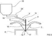
- the invention relates to a method and to an arrangement for feeding fine-grained matter such as concentrate or matte from a bin 10 for feed material into a reaction shaft 10 of a suspension smelting furnace las is illustrated in figures 2 to 14 .
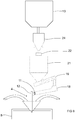
- Figure 15 illustrates feeding feed material in the form of granulated matter from a bin 10 for feed material into an electric furnace 1.
- the method comprises a first providing step for providing a feed material feeding arrangement 9 for feeding feed material from the bin 10 for feed material into the furnace space of the smelting furnace 1.
- the method comprises additionally a feeding step for feeding feed material from the bin 10 for feed material into the furnace space of the smelting furnace 1.
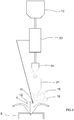
- the method comprises additionally a second providing step for providing at least one sensor 11 for measuring flow of feed material at a position between the bin 10 for feed material and the furnace space of the smelting furnace 1.
- the method comprises additionally a measuring step for measuring flow of feed material by means of said at least one sensor 11 at said position.
- the feed material is in the form of fine-grained matter such as concentrate or matte.
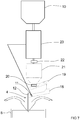
- the smelting furnace is a suspension smelting furnace 1 comprising a concentrate or matte burner 2 having reaction gas feeding means 3 and fine-grained matter feeding means 4.
- the fine-grained matter feeding means 4 of the concentrate or matte burner 2 comprises a fine-grained matter feed pipe 12 having a perimeter 5 and having a discharge opening 7 that opens into a reaction shaft 8 of the suspension smelting furnace 1.
- the first providing step for providing a feed material feeding arrangement 9 for feeding feed material from the bin 10 for feed material into the furnace space of the smelting furnace 1 is a step for providing a feed material feeding arrangement 9 for feeding fine-grained matter from the bin 10 for feed material into the fine-grained matter feeding means 4 of the concentrate or matte burner 2.
- the feeding step for feeding feed material from the bin 10 for feed material into the furnace space the smelting furnace is a step for feeding fine-grained matter from the bin 10 for feed material into the fine-grained matter feeding means 4 of the concentrate or matte burner 2 and for feeding fine-grained matter by means of the fine-grained matter feeding means 4 of the concentrate or matte burner 2 into the reaction shaft 8 of the suspension smelting furnace 1 i.e.
- the second providing step for providing at least one sensor 11 for measuring flow of feed material at a position between the bin 10 for feed material and the furnace space of the smelting furnace 1 is a step for providing at least one sensor 11 for measuring flow of fine-grained matter at a position between the bin 10 for feed matter and the discharge opening 7 of the fine-grained matter feed pipe 12 of the fine-grained matter feeding means 4 of the concentrate or matte burner 2.
- the measuring step for measuring flow of feed material by means of said at least one sensor 11 at said position is a step for measuring flow of feed material by means of said at least one sensor 11 at said position between the bin 10 for feed matter and the discharge opening 7 of the fine-grained matter feed pipe 12 of the fine-grained matter feeding means 4 of the concentrate or matte burner 2.
- the second providing step of the method may comprise providing the perimeter 5 of the fine-grained matter feed pipe 12 of the fine-grained matter feeding means 4 of the concentrate or matte burner 2 with at least one sensor 11 for measuring flow of fine-grained matter in the fine-grained matter feed pipe 12 of the fine-grained matter feeding means 4 of the concentrate or matte burner 2. It is for example possible in the embodiments shown in figures 2 to 8 , to provide the perimeter 5 of the fine-grained matter feed pipe 12 of the fine-grained matter feeding means 4 of the concentrate or matte burner 2 with at least one sensor 11 for measuring flow of fine-grained matter in the fine-grained matter feed pipe 12 of the fine-grained matter feeding means 4 of the concentrate or matte burner 2.
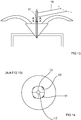
- the suspension smelting furnace 1 comprise a concentrate or matte burner 2, where the feed pipe 12 of the fine-grained matter feeding means 4 of the concentrate or matte burner 2 is divided into sectors 13.
- the second providing step of the method comprises providing each sector 13 with at least one sensor 11 for independently measuring flow within each sector 13. Such an embodiment is shown in figures 12 and 13 .
- the method includes providing each sector 13 of the feed pipe 12 with an adjustable damper means 27 for independently adjusting the flow of fine-grained matter within each sector 13 of the feed pipe 12.
- the feeding step includes independently adjusting the flow of fine-grained matter within each sector 13 of the feed pipe 12 by means of the adjustable damper means 27 provided in each sector 13 of the feed pipe 12 based on the flow of fine-grained matter independently measured within in each sector 13 of the feed pipe 12 by means of said at least one sensor 11 provided in each sector 13 of the feed pipe 12 in said measuring step.
- Such adjustable damper means 27 may be used for adjusting the distribution of the fine-grained matter in the concentrate or matte burner 2 and how the fine-grained matter is fed by means the concentrate or matte burner 2 into the reaction shaft 8 of the suspension smelting furnace.
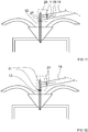
- the first providing step of the method may include providing a feed material feeding arrangement 9 having a downstream end in communication with the fine-grained matter feeding means 4 of the concentrate or matte burner 2, which downstream end is provided with partition means 28 for dividing the downstream end of the feed material feeding arrangement 9 into several feed channels 29 each feed channel 29 ending into a sector 13 of the feed pipe 12 of the fine-grained matter feeding means 4 of the concentrate or matte burner 2.
- a such embodiment may include providing each feed channel 29 of the feed material feeding arrangement 9 with an adjustable damper means 27 for independently adjusting the flow of fine-grained matter within each feed channel 29 of the feed material feeding arrangement 9.
- the feeding step may include independently adjusting the flow of fine-grained matter within each feed channel 29 of the feed material feeding arrangement 9 by means of the adjustable damper means 27 provided in each feed channel 29 of the feed material feeding arrangement 9 based on the flow of fine-grained matter independently measured within each sector 13 of the feed pipe 12 by means of said at least one sensor 11 provided in each sector 13 of the feed pipe 12 in said measuring step.
- a such embodiment is shown in figure 12 .
- the downstream end of the feed material feeding arrangement 9 is formed by a closed air slide conveyor 18 so that the downstream end of the closed air slide conveyor 18 is divided by partition means 28 into several feed channels 29.
- Such adjustable damper means 27 may be used for adjusting the distribution of the fine-grained matter in the concentrate or matte burner 2 and how the fine-grained matter is fed by means the concentrate or matte burner 2 into the reaction shaft 8 of the suspension smelting furnace.
- the method comprises providing a suspension smelting furnace 1 comprising a concentrate or matte burner 2 having the feed pipe 12 of the fine-grained matter feeding means 4 divided into sectors.
- the first providing step may in some embodiments include providing a feed material feeding arrangement 9 having a downstream end in communication with the fine-grained matter feeding means 4 of the concentrate or matte burner 2, which downstream end is provided with partition means 28 for dividing the downstream end of the feed material feeding arrangement 9 into several feed channels 29 each feed channel 29 ending into a sector 13 of the feed pipe 12 of the fine-grained matter feeding means 4 of the concentrate or matte burner 2.
- the second providing step includes providing each feed channel 29 of the feed material feeding arrangement 9 with at least one sensor 11 for independently measuring flow of fine-grained matter within each feed channel 29 of the feed material feeding arrangement 9.
- the measuring step includes independently measuring flow of fine-grained matter within each feed channel 29 of the feed material feeding arrangement 9.
- a such embodiment includes providing each sector 13 of the feed pipe 12 with an adjustable damper means 27 for independently adjusting the flow of fine-grained matter within each sector 13 of the feed pipe 12.
- the feeding step includes independently adjusting the flow of fine-grained matter within each sector 13 of the feed pipe 12 by means of the adjustable damper means 27 provided in each sector 13 of the feed pipe 12 based on the flow of fine-grained matter independently measured within each feed channel 29 of the feed material feeding arrangement 9 by means of said at least one sensor 11 provided in each feed channel 29 of the feed material feeding arrangement 9 in said measuring step.
- a such embodiment is shown in figure 11 .
- the downstream end of the feed material feeding arrangement 9 is formed by a closed air slide conveyor 18 so that the downstream end of the closed air slide conveyor 18 is divided by partition means 28 into several feed channels 29.
- Such adjustable damper means 27 may be used for adjusting the distribution of the fine-grained matter in the concentrate or matte burner 2 and how the fine-grained matter is fed by means the concentrate or matte burner 2 into the reaction shaft 8 of the suspension smelting furnace.
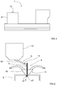
- the suspension smelting furnace may, as shown in figures 2 to 14 , comprise a concentrate or matte burner 2 having reaction gas feeding means 3 comprising an annular gas feeding channel 15 that surrounds the solid matter feed pipe 12 and having an annular gas discharge opening 16 opening into the reaction shaft 8 of the suspension smelting furnace 1.
- the suspension smelting furnace may, as shown in figures 2 to 14 , comprise a concentrate or matte burner 2 comprising a concentrate distributor 17 extending out from the discharge opening 7 of the solid matter feed pipe 12 and into the reaction shaft 8 of the suspension smelting furnace 1.
- the first providing step may in some embodiments of the method, as in the embodiments shown in figures 4 to 8 , comprise providing a feed material feeding arrangement 9 comprising a closed air slide conveyor 18 in communication with the fine-grained matter feeding means 4 of the concentrate or matte burner 2.
- the feeding step of the method comprises feeding the fine-grained matter into the fine-grained matter feeding means 4 of the concentrate or matte burner 2 by means of the closed air slide conveyor 18.
- the second providing step may comprise providing at least one sensor 11 for measuring flow of fine-grained matter in closed air slide conveyor 18 of the feed material feeding arrangement 9. It is for example possible that in the embodiments shown in figures 4 to 8 , to provide the closed air slide conveyor 18 with at least one sensor 11 for measuring flow of fine-grained matter in the closed air slide conveyor 18.
- the first providing step comprises providing a feed material feeding arrangement 9, where the bin 10 for fine grained-matter is configured for feeding the fine-grained matter into a closed air slide conveyor 18 and where the closed air slide conveyor 18 is configured for feeding the fine-grained matter into the fine-grained matter feeding means 4 of the concentrate or matte burner 2.
- the feeding step comprises feeding fine-grained matter into the closed air slide conveyor 18 from the bin 10 for fine grained-matter and feeding fine-grained matter from the closed air slide conveyor 18 into the fine-grained matter feeding means 4 of the concentrate or matte burner 2.
- the first providing step comprises providing a feed material feeding arrangement 9, where the bin 10 for fine grained-matter is configured for feeding the fine-grained matter into a conveyor 26 for feeding fine-grained matter into a closed air slide conveyor 18 and where the closed air slide conveyor 18 is configured for feeding the fine-grained matter into the fine-grained matter feeding means 4 of the concentrate or matte burner 2.
- the feeding step comprises feeding fine-grained matter into the conveyor 26 from the bin 10 for fine grained-matter and feeding fine-grained matter from the conveyor 26 into closed air slide conveyor 18 and feeding fine-grained matter from the closed air slide conveyor 18 into the fine-grained matter feeding means 4 of the concentrate or matte burner 2.
- the first providing step may in some embodiments of the method comprise providing a feed material feeding arrangement 9 comprising a controlling means 19, such as a screw conveyor (as in the embodiment shown in figures 4 to 8 ), a hose valve or a rotary valve or a multiple of these, in communication with the closed air slide conveyor 18.
- a controlling means 19 such as a screw conveyor (as in the embodiment shown in figures 4 to 8 ), a hose valve or a rotary valve or a multiple of these, in communication with the closed air slide conveyor 18.
- the feeding step comprises feeding fine-grained matter into the closed air slide conveyor 18 from the controlling means 19.
- the first providing step comprises providing a fine-grained matter feeding means 4 comprising an additional fine-grained matter feeding arrangement 25 for feeding additional fine-grained matter into the fine-grained matter feeding means 4 downstream of the at least one sensor 11 and that the method consequently comprises a second feeding step for feeding additional fine-grained matter into the fine-grained matter feeding means 4 by means of said additional fine-grained feeding arrangement 25.
- additional fine-grained matter may comprise at least one of the following: Silica, lime, limestone, reverts (i.e. ground mixture of recycled products and slag mixture), dust, electronic scrap, and solid coolant.
- the first providing step comprises providing a feed material feeding arrangement 9 where the bin 10 for fine grained-matter is configured for feeding the fine-grained matter into the controlling means 19 and where the controlling means 19 is configured for controlling the fine-grained matter into a closed air slide conveyor 18 and where the closed air slide conveyor 18 is configured for feeding fine-grained matter into the fine-grained matter feeding means 4 of the concentrate or matte burner 2.
- the feeding step comprises feeding fine-grained matter into the controlling means 19 from the bin 10 for fine grained-matter and feeding fine-grained matter from the controlling means 19 into the closed air slide conveyor 18.
- the feeding step comprises additionally feeding fine-grained matter from the closed air slide conveyor 18 into the fine-grained matter feeding means 4 of the concentrate or matte burner 2.
- the first providing step may comprise providing a loss-in-weight controller 20 between the bin 10 for fine grained-matter and the controlling means 19, for controlling feed of fine-grained matter from the bin 10 for fine grained-matter into the air slide conveyor 18.
- the method comprises additionally a controlling step for controlling feed of fine-grained matter from the bin 10 for fine grained-matter through controlling means 19 by means of the loss-in-weight controller 20.
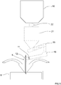
- the first providing step may in some embodiments of the method, as in the fourth embodiment shown in figure 5 , comprise providing a feed material feeding arrangement 9, where the bin 10 for fine grained-matter is configured for feeding the fine-grained matter into a dosing bin 21, and where a valve means 22 is provided between the bin 10 for fine grained-matter and the dosing bin 21 for opening and closing the communication between the bin 10 for fine grained-matter and the dosing bin 21.
- the feeding step comprises opening the valve means 22 before feeding fine-grained matter from the bin 10 for fine grained-matter into the dosing bin 21 and at least during but not restricted to this step the controlling means 19 can be regulated using the information from the sensor 11.
- the first providing step may in some embodiments of the method, as in the sixth embodiment shown in figure 7 , comprise providing a feed material feeding arrangement 9 comprising a dryer 23 between the bin 10 for fine grained-matter and the dosing bin 21, which the dryer 23 is configured for regulating the moisture rate of fine-grained matter.
- the feeding step comprises feeding fine-grained matter into the dryer 23 from the bin 10 for fine grained-matter, and feeding fine-grained matter from the dryer 23 into the dosing bin 21.
- Such embodiments of the method comprises additionally a regulating step for regulating the moisture rate of fine-grained matter by means of the dryer 23
- the first providing step may in some embodiments of the method, as in the fifth embodiment shown in figure 6 , comprise providing a feed material feeding arrangement 9 comprising a fluidization means 24 between the bin 10 for fine grained-matter and the dosing bin 21, and a filing valve22 between the fluidization means 24 and the dosing bin 21 for opening and closing the communication between the fluidization means 24 and the dosing bin 21.
- the feeding step comprises feeding fine-grained matter into the fluidization means 24 from the bin 10 for fine grained-matter, and feeding fine-grained matter from the fluidization means 24 into the dosing bin 21.
- Such embodiments of the method comprises additionally a fluidization step for fluidizing fine-grained matter in the fluidization means 24.
- the first providing step may in some embodiments of the method, as in the seventh embodiment shown in figure 8 , comprise providing a feed material feeding arrangement 9 comprising both a dryer 23 and a fluidization means 24 between the bin 10 for fine grained-matter and the dosing bin 21, and a first filling valve between the fluidization means 24 and the dosing bin 21 for opening and closing the communication between the fluidization means 24 and the dosing bin 21.
- the feeding step comprises feeding fine-grained matter into the dryer 23 from the bin 10 for fine grained-matter, feeding fine-grained matter from the dryer 23 into the fluidization means 24, and feeding fine-grained matter from the fluidization means 24 into the dosing bin 21.
- Such embodiments of the method comprises additionally a regulating step for regulating the moisture rate of fine-grained matter by means of the dryer 23.
- Such embodiments of the method comprises additionally a fluidization step for fluidizing fine-grained matter in the fluidization means 24.
- the first providing step comprises providing a feed material feeding arrangement 9 comprising a dryer 23
- the second providing step comprises preferably, but not necessarily, functionally connecting at least one sensor 11 and the dryer 23, and the method comprises a regulating step for regulating the dryer 23 on the basis of the flow of fine-grained matter measured by said sensor 11 functionally connected to the dryer 23.
- Figure 15 illustrated feeding feed material in the form of granulated material into a furnace space of an electric furnace from a bin 10.
- the second providing step comprises preferably, but not necessarily, providing a sensor 11 comprising at least one of the following: a tomography sensor such as an electrical capacitance tomography measuring sensor, an ultrasonic tomography measuring sensor, a radiometric sensor, and a microwave sensor.
- a tomography sensor such as an electrical capacitance tomography measuring sensor, an ultrasonic tomography measuring sensor, a radiometric sensor, and a microwave sensor.
- the arrangement comprises a feed material feeding arrangement 9 for feeding feed material from the bin 10 for feed material into the furnace space of the smelting furnace 1.
- the arrangement comprises at least one sensor 11 for measuring flow of feed material being arranged between the bin 10 for feed material and the furnace space of the smelting furnace 1.
- the feed material is in the form of fine-grained matter such as concentrate or matte and the smelting furnace is in the form of a suspension smelting furnace comprising a reaction shaft 8 and a concentrate or matte burner 2 having reaction gas feeding means 3 and fine-grained matter feeding means 4.
- the fine-grained matter feeding means 4 of the concentrate or matte burner 2 comprises a fine-grained matter feed pipe 12 having a perimeter 5 and having a discharge opening 7 that opens into the reaction shaft 8 of the suspension smelting furnace 1 i.e. into a furnace space of the suspension smelting furnace.
- the feed material feeding arrangement 9 for feeding feed material from the bin 10 for feed material into the furnace space of the smelting furnace 1 is configured for feeding fine-grained matter from the bin 10 for feed material into the fine-grained matter feeding means 4 of the concentrate or matte burner 2 for further feeding into the reaction shaft 8 of the suspension smelting furnace 1.
- At least one sensor 11 for measuring flow of feed material between the bin 10 for feed material and the furnace space of the smelting furnace 1 is arranged between the bin 10 for fine-grained matter and the discharge opening 7 of the fine-grained matter feed pipe 12 of the fine-grained matter feeding means 4 of the concentrate or matte burner 2.
- the perimeter 5 of the solid matter feed pipe 12 may be provided with at least one sensor 11 for measuring flow of fine-grained matter in the solid matter feed pipe 12. It is for example possible that in the embodiments shown in figures 2 to 8 , the perimeter 5 of the fine-grained matter feed pipe 12 of the fine-grained matter feeding means 4 of the concentrate or matte burner 2 is provided with at least one sensor 11 for measuring flow of fine-grained matter in the fine-grained matter feed pipe 12 of the fine-grained matter feeding means 4 of the concentrate or matte burner 2.
- the feed pipe 12 of the concentrate or matte burner 2 is divided into sectors 12 and each sector 13 is provided with at least one sensor 11 for independently measuring flow within each sector 13, as shown in figures 13 and 14 .
- each sector 13 of the feed pipe 12 is provided with an adjustable damper means 27 for independently adjusting the flow of fine-grained matter within each sector 13 of the feed pipe 12.
- each sensor 11 of each sector 13 of the feed pipe 12 may be functionally connected to at least one adjustable damper means 27 in a sector 13 of the feed pipe 12.
- Such adjustable damper means 27 may be used for adjusting the distribution of the fine-grained matter in the concentrate or matte burner 2 and how the fine-grained matter is fed by means the concentrate or matte burner 2 into the reaction shaft 8 of the suspension smelting furnace.
- the feed material feeding arrangement 9 has a downstream end in communication with the fine-grained matter feeding means 4 of the concentrate or matte burner 2, which downstream end is provided with partition means 28 for dividing the downstream end of the feed material feeding arrangement 9 into several feed channels 29 each feed channel 29 ending into a sector 13 of the feed pipe 12 of the fine-grained matter feeding means 4 of the concentrate or matte burner 2.
- each feed channel 29 of the feed material feeding arrangement 9 is provided with an adjustable damper means 27 for independently adjusting the flow of fine-grained matter within each feed channel 29 of the feed material feeding arrangement 9. A such embodiment is shown in figure 12 .
- each adjustable damper means 27 in each feed channel 29 may be functionally connected to at least sensor 11 of a sector 13 of the feed pipe 12.
- Such adjustable damper means 27 may be used for adjusting the distribution of the fine-grained matter in the concentrate or matte burner 2 and how the fine-grained matter is fed by means the concentrate or matte burner 2 into the reaction shaft 8 of the suspension smelting furnace.
- the feed material feeding arrangement 9 has a downstream end in communication with the fine-grained matter feeding means 4 of the concentrate or matte burner 2, which downstream end is provided with partition means 28 for dividing the downstream end of the feed material feeding arrangement 9 into several feed channels 29 each feed channel 29 ending into a sector 13 of the feed pipe 12 of the fine-grained matter feeding means 4 of the concentrate or matte burner 2.
- each feed channel 29 of the feed material feeding arrangement 9 is provided with at least one sensor 11 for independently measuring flow of fine-grained matter within each feed channel 29 of the feed material feeding arrangement 9.
- each sector 13 of the feed pipe 12 is provided with an adjustable damper means 27 for independently adjusting the flow of fine-grained matter within each sector 13 of the feed pipe 12.
- FIG 11 A such embodiment is shown in figure 11 .
- the downstream end of the feed material feeding arrangement 9 is formed by a closed air slide conveyor 18 so that the downstream end of the closed air slide conveyor 18 is divided by partition means 28 into several feed channels 29.
- each adjustable damper means 27 in each sector 13 of the feed pipe 12 may be functionally connected to at least sensor 11 in each feed channel 29.
- Such adjustable damper means 27 may be used for adjusting the distribution of the fine-grained matter in the concentrate or matte burner 2 and how the fine-grained matter is fed by means the concentrate or matte burner 2 into the reaction shaft 8 of the suspension smelting furnace.
- the reaction gas feeding means 3 of the concentrate or matte burner 2 may comprise an annular gas feeding channel 15 that surrounds the solid matter feed pipe 12 and having an annular gas discharge opening 16 opening into the reaction shaft 8 of the suspension smelting furnace 1.
- the concentrate or matte burner 2 may comprise a concentrate distributor 17 extending out from the discharge opening 7 of the solid matter feed pipe 12 and into the reaction shaft 8 of the suspension smelting furnace 1.
- the feed material feeding arrangement 9 may, as is shown in the embodiments shown in figures 2 to 8 , comprise an closed air slide conveyor 18 in communication with the fine-grained matter feeding means 4 of the concentrate or matte burner 2 so that the closed air slide conveyor 18 is configured for feeding the fine-grained matter into the fine-grained matter feeding means 4 of the concentrate or matte burner 2. If the feed material feeding arrangement 9 comprises such closed air slide conveyor 18, the closed air slide conveyor 18 may be provided with at least one sensor 11 for measuring flow of fine-grained matter in the closed air slide conveyor 18. It is for example possible that in the embodiments shown in figures 2 to 8 , the air slide is provided with at least one sensor 11 for measuring flow of fine-grained matter in the closed air slide conveyor 18.
- the arrangement comprises an additional fine-grained matter feeding arrangement 25 for feeding additional fine-grained matter into the fine-grained matter feeding means 4 downstream of the at least one sensor 11.
- additional fine-grained matter may comprise at least one of the following: Silica, lime, limestone, reverts (i.e. ground mixture of recycled products and slag mixture), dust, electronic scrap, and solid coolant.
- the feed material feeding arrangement 9 may, as is shown in the first embodiment shown in figure 2 , comprise an closed air slide conveyor 18 in communication with the bin 10 for fine-grained matter and in communication the fine-grained matter feeding means 4 of the concentrate or matte burner 2 so that the closed air slide conveyor 18 is configured for receiving fine-grained matter from the bin 10 for fine-grained matter and configured for feeding fine-grained matter into the fine-grained matter feeding means 4 of the concentrate or matte burner 2.
- the feed material feeding arrangement 9 may, as is shown in the second embodiment shown in figure 3 , comprise conveyor 26 that is in communication with the bin 10 for fine-grained matter and that is in communication with a closed air slide conveyor 18 that in turn is in communication with the fine-grained matter feeding means 4 of the concentrate or matte burner 2 so that the conveyor 26 is configured for receiving fine-grained matter from the bin 10 for feed material, the closed air slide conveyor 18 is configured for receiving fine-grained matter from the conveyor 26 and the fine-grained matter feeding means 4 of the concentrate or matte burner 2 is configured for receiving feed material from the closed air slide conveyor 18.
- the arrangement comprises an additional fine-grained matter feeding arrangement 25 for feeding additional fine-grained matter into the fine-grained matter feeding means 4 downstream of the at least one sensor 11.
- the second embodiment of the arrangement shown in figure 3 comprises preferably, but not necessarily, a loss-in-weight controller 20 between the conveyor 26 for fine-grained matter and the controlling means 19 for controlling feed of fine-grained matter from the bin 10 for fine grained-matter into the controlling means 19.
- the feed material feeding arrangement 9 may, as is shown in the third embodiment shown in figure 4 , comprise a controlling means 19 that is in communication with a closed air slide conveyor 18.
- the closed air slide conveyor 18 is in communication the fine-grained matter feeding means 4 of the concentrate or matte burner 2.
- the controlling means 19 is configured for receiving fine-grained matter from the bin 10 for feed material
- the closed air slide conveyor 18 is configured for receiving fine-grained matter from the controlling means 19
- the fine-grained matter feeding means 4 of the concentrate or matte burner 2 is configured for receiving feed material from the closed air slide conveyor 10.
- the arrangement comprises an additional fine-grained matter feeding arrangement 25 for feeding additional fine-grained matter into the fine-grained matter feeding means 4 downstream of the at least one sensor 11.
- additional fine-grained matter may comprise at least one of the following: Silica, lime, limestone, reverts (i.e. ground mixture of recycled products and slag mixture), dust, electronic scrap, and solid coolant.
- the feed material feeding arrangement 9 may, as is shown in the fourth embodiment shown in figure 5 , comprise a dosing bin 21 that is in communication with the bin 10 for feed material and with a controlling means 19.
- the controlling means 19 is in communication with a closed air slide conveyor 18.
- the closed air slide conveyor 18 is in communication the fine-grained matter feeding means 4 of the concentrate or matte burner 2.
- the dosing bin 21 is configured for receiving fine-grained matter from the bin 10 for feed material
- the controlling means 19 is configured for receiving fine-grained matter from the controlling means 19
- the closed air slide conveyor 18 is configured for receiving fine-grained matter from the controlling means 19
- the fine-grained matter feeding means 4 of the concentrate or matte burner 2 is configured for receiving feed material from the closed air slide conveyor 18.
- the arrangement comprises an additional fine-grained matter feeding arrangement 25 for feeding additional fine-grained matter into the fine-grained matter feeding means 4 downstream of the at least one sensor 11.
- the feed material feeding arrangement 9 may, as is shown in the fifth embodiment of the arrangement shown in figure 6 , comprise a fluidization means 24 in communication with the bin 10 for fine-grained matter and in communication with a dosing bin 21.
- the dosing bin 21 is in communication with a controlling means 19 that is in communication with a closed air slide conveyor 18 that in turn is in communication the fine-grained matter feeding means 4 of the concentrate or matte burner 2.
- the arrangement comprises an additional fine-grained matter feeding arrangement 25 for feeding additional fine-grained matter into the fine-grained matter feeding means 4 downstream of the at least one sensor 11.
- additional fine-grained matter may comprise at least one of the following: Silica, lime, limestone, reverts (i.e. ground mixture of recycled products and slag mixture), dust, electronic scrap, and solid coolant.
- the feed material feeding arrangement 9 may, as is shown in the fifth embodiment shown in figure 6 , comprise a fluidization means 24 in communication with the bin 10 for fine-grained matter, a dosing bin 21 that is in communication with the fluidization means 24 and with a controlling means 19.
- the controlling means 19 is in communication with a closed air slide conveyor 18.
- the closed air slide conveyor 18 is in communication the fine-grained matter feeding means 4 of the concentrate or matte burner 2.
- the fluidization means 24 is configured for receiving fine-grained matter from the bin 10 for feed material
- the dosing bin 21 is configured for receiving fine-grained matter from the fluidization means 24
- the controlling means 19 is configured for receiving fine-grained matter from the controlling means 19
- the closed air slide conveyor 18 is configured for receiving fine-grained matter from the controlling means 19
- the fine-grained matter feeding means 4 of the concentrate or matte burner 2 is configured for receiving feed material from the closed air slide conveyor 18.
- the arrangement comprises an additional fine-grained matter feeding arrangement 25 for feeding additional fine-grained matter into the fine-grained matter feeding means 4 downstream of the at least one sensor 11.
- the fifth embodiment comprises preferably, but not necessarily, a valve means 22 between the bin 10 for fine grained-matter and the fluidization means 24.
- the fifth embodiment comprises preferably, but not necessarily, a valve means 22 between the fluidization means 24 and the dosing bin 21.
- the fifth embodiment comprises preferably, but not necessarily, a loss-in-weight controller 20 between the dosing bin 21 and the controlling means 19 for controlling feed of fine-grained matter from the dosing bin 21 into the controlling means 19.
- the arrangement comprises preferably, but not necessarily, an additional fine-grained matter feeding arrangement 25 for feeding additional fine-grained matter into the fine-grained matter feeding means 4 downstream of the at least one sensor 11.
- Such additional fine-grained matter may comprise at least one of the following: Silica, lime, limestone, reverts (i.e. ground mixture of recycled products and slag mixture), dust, electronic scrap, and solid coolant.
- the feed material feeding arrangement 9 may, as is shown in the sixth embodiment of the arrangement shown in figure 7 , comprise a dryer 23 in communication with the bin 10 for fine-grained matter and in communication with a dosing bin 21.
- the dosing bin 21 is in communication with a controlling means 19 that is in communication with a closed air slide conveyor 18 that in turn is in communication the fine-grained matter feeding means 4 of the concentrate or matte burner 2.
- the feed material feeding arrangement 9 may, as is shown in the sixth embodiment shown in figure 7 , comprise a dryer 23 in communication with the bin 10 for fine-grained matter, a dosing bin 21 that is in communication with the dryer 23 and with a controlling means 19.
- the controlling means 19 is in communication with a closed air slide conveyor 18.
- the closed air slide conveyor 18 is in communication the fine-grained matter feeding means 4 of the concentrate or matte burner 2.
- the dryer 23 is configured for receiving fine-grained matter from the bin 10 for feed material
- the dosing bin 21 is configured for receiving fine-grained matter from the dryer 23
- the controlling means 19 is configured for receiving fine-grained matter from the controlling means 19
- the closed air slide conveyor 18 is configured for receiving fine-grained matter from the controlling means 19
- the fine-grained matter feeding means 4 of the concentrate or matte burner 2 is configured for receiving feed material from the closed air slide conveyor 18.
- the arrangement comprises an additional fine-grained matter feeding arrangement 25 for feeding additional fine-grained matter into the fine-grained matter feeding means 4 downstream of the at least one sensor 11.
- the feed material feeding arrangement 9 may, as is shown in the seventh embodiment of the arrangement shown in figure 8 , comprise a dryer 23 in communication with the bin 10 for fine-grained matter and in communication with a fluidization means 24.
- the fluidization means 24 is in communication with a dosing bin 21.
- the dosing bin 21 is in communication with a controlling mean 19.
- the controlling mean 19 is in communication with a closed air slide conveyor 18.
- the closed air slide conveyor 18 is in communication the fine-grained matter feeding means 4 of the concentrate or matte burner 2.
- the feed material feeding arrangement 9 may, as is shown in the seventh embodiment shown in figure 8 , comprise a dryer 23 in communication with the bin 10 for fine-grained matter, a fluidization means 24 in communication with the dryer 23 and with a dosing bin 21, and a controlling means 19 in communication with the dosing bin 21 and a closed air slide conveyor 18.
- the closed air slide conveyor 18 is in communication the fine-grained matter feeding means 4 of the concentrate or matte burner 2.
- the dryer 23 is configured for receiving fine-grained matter from the bin 10 for feed material
- the fluidization means 24 is configured for receiving fine-grained matter from the dryer 23
- the dosing bin 21 is configured for receiving fine-grained matter from the fluidization means 23
- the controlling means 19 is configured for receiving fine-grained matter from the controlling means 19
- the closed air slide conveyor 18 is configured for receiving fine-grained matter from the controlling means 19
- the fine-grained matter feeding means 4 of the concentrate or matte burner 2 is configured for receiving feed material from the closed air slide conveyor 18.
- the arrangement comprises an additional fine-grained matter feeding arrangement 25 for feeding additional fine-grained matter into the fine-grained matter feeding means 4 downstream of the at least one sensor 11.
- additional fine-grained matter may comprise at least one of the following: Silica, lime, limestone, reverts (i.e. ground mixture of recycled products and slag mixture), dust, electronic scrap, and solid coolant.
- the arrangement comprises a dryer 23 as is the case in the sixth embodiment shown in figure 7 and in the seventh embodiment shown in figure 8 , the arrangement comprises preferably, but not necessarily, a sensor 11 for measuring flow of fine grained matter, which sensor 11 is functionally connected to the dryer 23 for controlling the dryer 23 based on the measured flow of fine grained-matter.
- Figure 15 shows an arrangement for feeding into an electric furnace.
- the arrangement comprises a sensor 11 comprising preferably at least one of the following: a tomography sensor such as an electrical capacitance tomography measuring sensor, an ultrasonic tomography measuring sensor, a radiometric sensor, and a microwave sensor.
- a tomography sensor such as an electrical capacitance tomography measuring sensor, an ultrasonic tomography measuring sensor, a radiometric sensor, and a microwave sensor.
Landscapes
- Engineering & Computer Science (AREA)
- Mechanical Engineering (AREA)
- General Engineering & Computer Science (AREA)
- Physics & Mathematics (AREA)
- General Physics & Mathematics (AREA)
- Fluid Mechanics (AREA)
- Chemical & Material Sciences (AREA)
- Materials Engineering (AREA)
- Metallurgy (AREA)
- Organic Chemistry (AREA)
- Manufacturing & Machinery (AREA)
- Automation & Control Theory (AREA)
- Manufacture And Refinement Of Metals (AREA)
- Furnace Charging Or Discharging (AREA)
- Vertical, Hearth, Or Arc Furnaces (AREA)
- General Preparation And Processing Of Foods (AREA)
Claims (11)
- Procédé d'amenée de matière à grains fins telle que de concentré ou de matte à partir d'une trémie (10) vers une cuve de réaction (8) d'un four de fusion en suspension (1) comprenant un brûleur de concentré ou de matte (2) comportant un moyen d'alimentation de gaz réactionnel (3) et un moyen d'alimentation de matière à grains fins (4), ledit moyen d'alimentation de matière à grains fins (4) du brûleur de concentré ou de matte (2) comprenant un conduit d'amenée de matière à grains fins (12) comportant un périmètre (5) et comportant un orifice de sortie (7) qui débouche dans la cuve de réaction (8) du four de fusion en suspension (1), ledit procédé comprenant :une première étape de fourniture pour fournir un agencement d'alimentation en matériau d'amenée (9) pour l'amenée d'une matière à grains fins à partir de la trémie (10) vers le moyen d'alimentation de matière à grains fins (4) du brûleur de concentré ou de matte (2),une étape d'amenée pour amener une matière à grains fins (10) à partir de la trémie (10) vers le moyen d'alimentation de matière à grains fins (4) du brûleur de concentré ou de matte (2) et pour amener la matière à grains fins dans la cuve de réaction (8) du four de fusion en suspension (1) moyennant le moyen d'alimentation de matière à grains fins (4) du brûleur de concentré ou de matte (2),une deuxième étape de fourniture pour fournir au moins un capteur (11) pour mesurer le débit de la matière à grains fins en une position entre la trémie (10) et l'orifice de sortie (7) du conduit d'amenée de matière à grains fins (12) du moyen d'alimentation de matière à grains fins (4) du brûleur de concentré ou de matte (2), etune étape de mesure pour mesurer le débit du matériau d'amenée moyennant ledit au moins un capteur (11) en ladite position entre la trémie (10) et l'orifice de sortie (7) du conduit d'amenée de matière à grains fins (12) du moyen d'alimentation de matière à grains fins (4) du brûleur de concentré ou de matte (2),caractérisé en ce quele conduit d'amenée (12) du moyen d'alimentation de matière à grains fins (4) est divisé en secteurs (13),la deuxième étape de fourniture comprend le fait de prévoir en chaque secteur (13) du conduit d'amenée (12) au moins un capteur (11) pour mesurer de manière indépendante le débit de la matière à grains fins en chaque secteur (13) du conduit d'amenée (12), etl'étape de mesure comprend le fait de mesurer de manière indépendante le débit de la matière à grains fins en chaque secteur (13) du conduit d'amenée (12) moyennant ledit au moins un capteur (11).
- Procédé selon la revendication 1, caractérisé en ce que
la deuxième étape de fourniture comprend le fait de prévoir au périmètre (5) du conduit d'amenée de matière solide (12) du moyen d'alimentation de matière à grains fins (4) du brûleur de concentré ou de matte (2) au moins un capteur (11) pour mesurer le débit de la matière à grains fins dans le conduit d'amenée de matière solide (12) du moyen d'alimentation de matière à grains fins (4) du brûleur de concentré ou de matte (2) moyennant ledit au moins un capteur (11). - Procédé selon la revendication 1 ou 2, caractérisé
par le fait de prévoir en chaque secteur (13) du conduit d'amenée (12) un moyen de clapet réglable (27) pour régler de manière indépendante le débit de la matière à grains fins en chaque secteur (13) du conduit d'amenée (12), et
en ce que l'étape d'amenée comprend le réglage indépendant du débit de la matière à grains fins en chaque secteur (13) du conduit d'amenée (12) moyennant le moyen de clapet réglable (27) prévu en chaque secteur (13) du conduit d'amenée (12) sur la base du débit de matière à grains fins mesuré de manière indépendante en chaque secteur (13) du conduit d'amenée (12) moyennant ledit au moins un capteur (11) prévu en chaque secteur (13) du conduit d'amenée (12) dans ladite étape de mesure. - Procédé selon l'une des revendications 1 à 3, caractérisé
en ce que la première étape de fourniture comprend le fait de fournir un agencement d'alimentation en matériau d'amenée (9) comportant une extrémité aval en communication avec le moyen d'alimentation de matière à grains fins (4) du brûleur de concentré ou de matte (2), ladite extrémité aval (28) étant pourvue d'un moyen de partitionnement (28) pour diviser en plusieurs canaux d'amenée (29) l'extrémité aval de l'agencement d'alimentation en matériau d'amenée (9), chaque canal d'amenée (29) débouchant dans un secteur (13) du conduit d'amenée (12) du moyen d'alimentation de matière à grains fins (4) du brûleur de concentré ou de matte (2). - Procédé selon la revendication 4, caractérisé
par le fait de prévoir en chaque canal d'amenée (29) de l'agencement d'alimentation en matériau d'amenée (9) un moyen de clapet réglable (27) pour régler de manière indépendante le débit de la matière à grains fins en chaque canal d'amenée (29) de l'agencement d'alimentation en matériau d'amenée (9), et
en ce que l'étape d'amenée comprend le réglage indépendant du débit de la matière à grains fins en chaque canal d'amenée (29) de l'agencement d'alimentation en matériau d'amenée (9) moyennant le moyen de clapet réglable (27) prévu en chaque canal d'amenée (29) de l'agencement d'alimentation en matériau d'amenée (9) sur la base du débit de matière à grains fins mesuré de manière indépendant en chaque secteur (13) du conduit d'amenée (12) moyennant ledit au moins un capteur (11) prévu en chaque secteur (13) du conduit d'amenée (12) dans ladite étape de mesure. - Procédé selon la revendication 4, caractérisé
en ce que la deuxième étape de fourniture comprend le fait de prévoir en chaque canal d'amenée (29) de l'agencement d'alimentation en matériau d'amenée (9) au moins un capteur (11) pour mesurer de manière indépendante le débit de la matière à grains fins en chaque canal d'amenée (29) de l'agencement d'alimentation en matériau d'amenée (9),
en ce que l'étape de mesure comprend le fait de mesurer de manière indépendante le débit de la matière à grains fins en chaque canal d'amenée (29) de l'agencement d'alimentation en matériau d'amenée (9),
par le fait de prévoir en chaque secteur (13) du conduit d'amenée (12) un moyen de clapet réglable (27) pour régler de manière indépendante le débit de la matière à grains fins en chaque secteur (13) du conduit d'amenée (12), et
en ce que l'étape d'amenée comprend le réglage indépendant du débit de la matière à grains fins en chaque secteur (13) du conduit d'amenée (12) moyennant le moyen de clapet réglable (27) prévu en chaque secteur (13) du conduit d'amenée (12) sur la base du débit de matière à grains fins mesuré de manière indépendante en chaque canal d'amenée (29) de l'agencement d'alimentation en matériau d'amenée (9) moyennant ledit au moins un capteur (11) prévu en chaque canal d'amenée (29) de l'agencement d'alimentation en matériau d'amenée (9) dans ladite étape de mesure. - Agencement d'amenée de matière à grains fins telle que de concentré ou de matte à partir d'une trémie (10) vers une cuve de réaction (8) d'un four de fusion en suspension (1) comprenant un brûleur de concentré ou de matte (2) comportant un moyen d'alimentation de gaz réactionnel (3) et un moyen d'alimentation de matière à grains fins (4),
ledit moyen d'alimentation de matière à grains fins (4) du brûleur de concentré ou de matte (2) comprenant un conduit d'amenée de matière à grains fins (12) comportant un périmètre (5) et comportant un orifice de sortie (7) qui débouche dans la cuve de réaction (8) du four de fusion en suspension (1),
ledit agencement comprenant un agencement d'alimentation en matériau d'amenée (9) configuré pour amener une matière à grains fins à partir d'une trémie (10) vers le moyen d'alimentation de matière à grains fins (4) du brûleur de concentré ou de matte (2), et
au moins un capteur (11) pour mesurer le débit du matériau d'amenée étant disposé entre la trémie (10) et l'orifice de sortie (7) du conduit d'amenée de matière à grains fins (12) du moyen d'alimentation de matière à grains fins (4) du brûleur de concentré ou de matte (2),
caractérisé en ce que
le conduit d'amenée (12) du brûleur de concentré ou de matte (2) est divisé en secteurs (13), et
chaque secteur (13) du conduit d'amenée (12) est pourvu d'au moins un capteur (11) pour mesurer de manière indépendante le débit de la matière à grains fins en chaque secteur (13) du conduit d'amenée (12). - Agencement selon la revendication 7, caractérisé en ce que
le périmètre (5) du conduit d'amenée de matière solide (12) est pourvu d'au moins un capteur (11) pour mesurer le débit de la matière à grains fins dans le conduit d'amenée de matière solide (12). - Agencement selon la revendication 7 ou 8, caractérisé en ce que chaque secteur (13) du conduit d'amenée (12) est pourvu d'un moyen de clapet réglable (27) pour régler de manière indépendante le débit de la matière à grains fins en chaque secteur (13) du conduit d'amenée (12),
- Agencement selon l'une des revendications 7 à 9, caractérisé en ce que
l'agencement d'alimentation en matériau d'amenée (9) comporte une extrémité aval en communication avec le moyen d'alimentation de matière à grains fins (4) du brûleur de concentré ou de matte (2), ladite extrémité aval (28) étant pourvue d'un moyen de partitionnement (28) pour diviser l'extrémité aval de l'agencement d'alimentation en matériau d'amenée (9) en plusieurs canaux d'amenée (29), chaque canal d'amenée (29) débouchant dans un secteur (13) du conduit d'amenée (12) du moyen d'alimentation de matière à grains fins (4) du brûleur de concentré ou de matte (2). - Agencement selon la revendication 10, caractérisé en ce que
chaque canal d'amenée (29) de l'agencement d'alimentation en matériau d'amenée (9) est pourvu d'un moyen de clapet réglable (27) pour régler de manière indépendante le débit de la matière à grains fins en chaque canal d'amenée (29) de l'agencement d'alimentation en matériau d'amenée (9).
Priority Applications (2)
| Application Number | Priority Date | Filing Date | Title |
|---|---|---|---|
| RS20210508A RS61784B1 (sr) | 2013-04-08 | 2014-04-07 | Metoda i uređenje za dopremanje ulaznog materijala iz kontejnera za ulazni materijal u prostor peći u peći za topljenje |
| PL14782335T PL2984459T3 (pl) | 2013-04-08 | 2014-04-07 | Sposób i układ do dostarczania materiału zasilającego z zasobnika na materiał zasilający do przestrzeni roboczej pieca do wytapiania |
Applications Claiming Priority (2)
| Application Number | Priority Date | Filing Date | Title |
|---|---|---|---|
| FI20135334A FI125166B (en) | 2013-04-08 | 2013-04-08 | PROCEDURES AND ARRANGEMENTS FOR FEEDING RAW MATERIAL FROM A RAW MATERIAL CONTAINER INTO A OVEN OVEN SPACE |
| PCT/FI2014/050241 WO2014167176A1 (fr) | 2013-04-08 | 2014-04-07 | Procédé et agencement pour introduire un matériau d'alimentation à partir d'un silo pour matériau d'alimentation dans un espace de four d'un four de fusion |
Publications (4)
| Publication Number | Publication Date |
|---|---|
| EP2984459A1 EP2984459A1 (fr) | 2016-02-17 |
| EP2984459A4 EP2984459A4 (fr) | 2016-11-23 |
| EP2984459B1 true EP2984459B1 (fr) | 2021-02-17 |
| EP2984459B8 EP2984459B8 (fr) | 2021-04-07 |
Family
ID=51688993
Family Applications (1)
| Application Number | Title | Priority Date | Filing Date |
|---|---|---|---|
| EP14782335.5A Active EP2984459B8 (fr) | 2013-04-08 | 2014-04-07 | Procédé et agencement pour introduire un matériau d'alimentation à partir d'un silo pour matériau d'alimentation dans un espace de four d'un four de fusion |
Country Status (13)
| Country | Link |
|---|---|
| US (1) | US10605531B2 (fr) |
| EP (1) | EP2984459B8 (fr) |
| KR (1) | KR101777938B1 (fr) |
| CN (1) | CN105431714A (fr) |
| BR (1) | BR112015025375B1 (fr) |
| CA (1) | CA2908294C (fr) |
| CL (1) | CL2015002934A1 (fr) |
| EA (1) | EA029267B1 (fr) |
| ES (1) | ES2869304T3 (fr) |
| FI (1) | FI125166B (fr) |
| PL (1) | PL2984459T3 (fr) |
| RS (1) | RS61784B1 (fr) |
| WO (1) | WO2014167176A1 (fr) |
Families Citing this family (5)
| Publication number | Priority date | Publication date | Assignee | Title |
|---|---|---|---|---|
| CN110612424A (zh) * | 2017-05-29 | 2019-12-24 | 奥图泰(芬兰)公司 | 用于控制悬浮熔炼炉的燃烧器的方法和装置 |
| JP6510626B2 (ja) * | 2017-12-12 | 2019-05-08 | パンパシフィック・カッパー株式会社 | 原料供給装置及び原料供給方法、並びに自溶炉 |
| RU2682910C1 (ru) * | 2018-03-06 | 2019-03-22 | Федеральное государственное бюджетное образовательное учреждение высшего образования "Оренбургский государственный университет" | Загрузочное устройство шахтной печи |
| KR200495639Y1 (ko) | 2020-12-15 | 2022-07-13 | 메트소 오토텍 핀란드 오이 | 피드 게이트 밸브 장치 및 야금로 |
| WO2024180485A1 (fr) * | 2023-02-28 | 2024-09-06 | Flsmidth A/S | Surveillance du niveau de remplissage dans le tube de pitot d'un four a cuve |
Family Cites Families (21)
| Publication number | Priority date | Publication date | Assignee | Title |
|---|---|---|---|---|
| GB1270112A (en) * | 1968-05-17 | 1972-04-12 | Nat Res Dev | Improvements in or relating to the measurement of the flow of particulate material |
| JPS5711938B2 (fr) | 1974-02-15 | 1982-03-08 | ||
| JPS5949421A (ja) | 1982-09-11 | 1984-03-22 | Babcock Hitachi Kk | 微粉炭の分配量制御装置 |
| IE76714B1 (en) | 1996-04-19 | 1997-10-22 | Auro Environmental Ltd | Apparatus for measuring the velocity of a fluid flowing in a conduit |
| FI105828B (fi) | 1999-05-31 | 2000-10-13 | Outokumpu Oy | Laitteisto suspensiosulatusuunin rikastepolttimen jauhemaisen materiaalin syötön tasaamiseksi |
| JP2003013152A (ja) | 2001-07-03 | 2003-01-15 | Mitsui Mining & Smelting Co Ltd | 自溶炉の装入鉱石装入方法 |
| FI117769B (fi) | 2004-01-15 | 2007-02-15 | Outokumpu Technology Oyj | Suspensiosulatusuunin syöttöjärjestelmä |
| CA2577970A1 (fr) | 2004-09-08 | 2006-03-16 | Headwaters Incorporated | Procede et systeme de pretraitement de cendres volantes |
| DE102005029552A1 (de) | 2005-06-25 | 2007-01-04 | Max Bögl Bauunternehmung GmbH & Co. KG | Feste Fahrbahn im Tunnel |
| US20070000416A1 (en) * | 2005-06-30 | 2007-01-04 | General Electric Company | Method and System for controlling coal flow |
| JP5087879B2 (ja) * | 2006-08-03 | 2012-12-05 | 住友金属工業株式会社 | 粉体吹込み方法 |
| FI20061124L (fi) | 2006-12-15 | 2008-06-16 | Outotec Oyj | Menetelmä ja laitteisto sulatusuuniin syötettävän materiaalin esikäsittelemiseksi |
| JP4814137B2 (ja) | 2007-03-26 | 2011-11-16 | 三菱重工業株式会社 | 微粉炭濃度調整装置 |
| CN101663537B (zh) | 2007-04-13 | 2012-01-11 | 巴布考克日立株式会社 | 微粉煤燃烧锅炉 |
| GB0717080D0 (en) * | 2007-09-03 | 2007-10-10 | Univ Manchester | Methods and apparatus relating to fluidised beds |
| KR100989733B1 (ko) | 2008-09-29 | 2010-10-26 | 현대제철 주식회사 | 부원료 투입 제어장치 및 방법 |
| WO2011002793A1 (fr) * | 2009-06-30 | 2011-01-06 | The University Of Connecticut | Technique de détection mecap appliquée à la tomographie par capacité électronique améliorée |
| FI122306B (fi) | 2009-12-11 | 2011-11-30 | Outotec Oyj | Järjestely suspensiosulatusuunin rikastepolttimen jauhemaisen kiintoaineen syötön tasaamiseksi |
| US9103592B2 (en) | 2011-05-06 | 2015-08-11 | Hatch Ltd. | Burner with velocity adjustment for flash smelter |
| US8963562B2 (en) | 2011-08-31 | 2015-02-24 | General Electric Company | Transducer configurations and methods for transducer positioning in electrical impedance tomography |
| FI124535B (en) | 2012-09-19 | 2014-10-15 | Outotec Oyj | A method and arrangement for feeding finely divided material to a slurry furnace concentrate burner or a rock burner, and control means and a computer program product |
-
2013
- 2013-04-08 FI FI20135334A patent/FI125166B/en not_active IP Right Cessation
-
2014
- 2014-04-07 WO PCT/FI2014/050241 patent/WO2014167176A1/fr active Application Filing
- 2014-04-07 EA EA201591776A patent/EA029267B1/ru not_active IP Right Cessation
- 2014-04-07 PL PL14782335T patent/PL2984459T3/pl unknown
- 2014-04-07 BR BR112015025375-0A patent/BR112015025375B1/pt not_active IP Right Cessation
- 2014-04-07 KR KR1020157030328A patent/KR101777938B1/ko active IP Right Grant
- 2014-04-07 EP EP14782335.5A patent/EP2984459B8/fr active Active
- 2014-04-07 ES ES14782335T patent/ES2869304T3/es active Active
- 2014-04-07 RS RS20210508A patent/RS61784B1/sr unknown
- 2014-04-07 CA CA2908294A patent/CA2908294C/fr not_active Expired - Fee Related
- 2014-04-07 CN CN201480022599.7A patent/CN105431714A/zh active Pending
- 2014-04-07 US US14/782,569 patent/US10605531B2/en active Active
-
2015
- 2015-10-02 CL CL2015002934A patent/CL2015002934A1/es unknown
Non-Patent Citations (1)
| Title |
|---|
| None * |
Also Published As
| Publication number | Publication date |
|---|---|
| CA2908294C (fr) | 2018-06-05 |
| KR101777938B1 (ko) | 2017-09-12 |
| ES2869304T3 (es) | 2021-10-25 |
| CN105431714A (zh) | 2016-03-23 |
| CL2015002934A1 (es) | 2016-06-24 |
| EA029267B1 (ru) | 2018-02-28 |
| EA201591776A1 (ru) | 2016-04-29 |
| RS61784B1 (sr) | 2021-06-30 |
| PL2984459T3 (pl) | 2021-10-11 |
| EP2984459A4 (fr) | 2016-11-23 |
| EP2984459B8 (fr) | 2021-04-07 |
| CA2908294A1 (fr) | 2014-10-16 |
| FI20135334A (fi) | 2014-10-09 |
| BR112015025375B1 (pt) | 2020-12-01 |
| US10605531B2 (en) | 2020-03-31 |
| WO2014167176A1 (fr) | 2014-10-16 |
| EP2984459A1 (fr) | 2016-02-17 |
| US20160040935A1 (en) | 2016-02-11 |
| BR112015025375A2 (pt) | 2017-07-18 |
| FI125166B (en) | 2015-06-30 |
| KR20150139545A (ko) | 2015-12-11 |
Similar Documents
| Publication | Publication Date | Title |
|---|---|---|
| EP2984459B1 (fr) | Procédé et agencement pour introduire un matériau d'alimentation à partir d'un silo pour matériau d'alimentation dans un espace de four d'un four de fusion | |
| EP3011244B1 (fr) | Conditionneur d'écoulement d'alimentation pour des matériaux d'alimentation en particules | |
| CN103693416B (zh) | 烧结矿配料控制装置及控制方法 | |
| UA90201C2 (ru) | Многобункерная загрузочная установка для шахтной печи и доменная печь, содержащая загрузочную установку | |
| CN1237193C (zh) | 用于将粉末材料均匀输送到悬浮冶炼炉的精矿燃烧器内的装置 | |
| CN103744441A (zh) | 一种烟丝物料流量的控制装置及方法 | |
| JP2007031758A (ja) | 微粉炭吹き込み高炉操業方法 | |
| CN106466581A (zh) | 一种高温粉体物料自动加料装置及其应用 | |
| JP2018062681A (ja) | 高炉の原料混合比率推定方法 | |
| CN103033055A (zh) | 烧结机主抽风机风量控制方法及系统 | |
| EP2588634B1 (fr) | Four de fusion en suspension et brûleur de concentré | |
| EP3368825A1 (fr) | Brûleur et appareil d'alimentation en solides fins pour brûleur | |
| CN102519566B (zh) | 配料控制系统 | |
| JP5971195B2 (ja) | 高炉における粉粒体流量制御方法 | |
| EP3676534B1 (fr) | Dispositif de distribution de mélange d'alimentation pour un brûleur | |
| CN104501202B (zh) | 工业窑炉燃烧器煤粉定量分配方法 | |
| KR101534126B1 (ko) | 원료 장입 장치 및 원료 장입 방법 | |
| JP2017171463A (ja) | 原料の切出し輸送方法およびその設備 | |
| JP6558518B1 (ja) | 高炉の原料装入方法 | |
| RU2456353C2 (ru) | Способ автоматического управления содержанием меди в штейне | |
| JP2005133170A (ja) | 高炉原料の切り出し方法及び高炉の操業方法 | |
| KR20100130729A (ko) | 마이크로웨이브 및 정전기 감지를 이용한 분체 유량 제어 장치 및 방법 | |
| JPH02182811A (ja) | 偏流防止機能を有するベルレス高炉の炉頂装入装置 | |
| JP2008260990A (ja) | 原料切出しフィーダの制御方法および装置 | |
| JP2007269877A (ja) | コークス用原料炭の調湿方法 |
Legal Events
| Date | Code | Title | Description |
|---|---|---|---|
| PUAI | Public reference made under article 153(3) epc to a published international application that has entered the european phase |
Free format text: ORIGINAL CODE: 0009012 |
|
| 17P | Request for examination filed |
Effective date: 20151022 |
|
| AK | Designated contracting states |
Kind code of ref document: A1 Designated state(s): AL AT BE BG CH CY CZ DE DK EE ES FI FR GB GR HR HU IE IS IT LI LT LU LV MC MK MT NL NO PL PT RO RS SE SI SK SM TR |
|
| AX | Request for extension of the european patent |
Extension state: BA ME |
|
| DAX | Request for extension of the european patent (deleted) | ||
| RAP1 | Party data changed (applicant data changed or rights of an application transferred) |
Owner name: OUTOTEC (FINLAND) OY |
|
| A4 | Supplementary search report drawn up and despatched |
Effective date: 20161020 |
|
| RIC1 | Information provided on ipc code assigned before grant |
Ipc: F27D 3/10 20060101ALI20161014BHEP Ipc: C22B 5/02 20060101ALI20161014BHEP Ipc: B65G 53/66 20060101ALI20161014BHEP Ipc: F27D 3/00 20060101ALI20161014BHEP Ipc: G01F 1/76 20060101ALI20161014BHEP Ipc: G01F 1/74 20060101AFI20161014BHEP Ipc: G05D 7/06 20060101ALI20161014BHEP Ipc: G01G 11/08 20060101ALI20161014BHEP Ipc: F27B 1/20 20060101ALI20161014BHEP |
|
| STAA | Information on the status of an ep patent application or granted ep patent |
Free format text: STATUS: EXAMINATION IS IN PROGRESS |
|
| 17Q | First examination report despatched |
Effective date: 20190204 |
|
| GRAP | Despatch of communication of intention to grant a patent |
Free format text: ORIGINAL CODE: EPIDOSNIGR1 |
|
| STAA | Information on the status of an ep patent application or granted ep patent |
Free format text: STATUS: GRANT OF PATENT IS INTENDED |
|
| INTG | Intention to grant announced |
Effective date: 20201021 |
|
| GRAS | Grant fee paid |
Free format text: ORIGINAL CODE: EPIDOSNIGR3 |
|
| GRAA | (expected) grant |
Free format text: ORIGINAL CODE: 0009210 |
|
| STAA | Information on the status of an ep patent application or granted ep patent |
Free format text: STATUS: THE PATENT HAS BEEN GRANTED |
|
| AK | Designated contracting states |
Kind code of ref document: B1 Designated state(s): AL AT BE BG CH CY CZ DE DK EE ES FI FR GB GR HR HU IE IS IT LI LT LU LV MC MK MT NL NO PL PT RO RS SE SI SK SM TR |
|
| REG | Reference to a national code |
Ref country code: GB Ref legal event code: FG4D |
|
| REG | Reference to a national code |
Ref country code: CH Ref legal event code: EP |
|
| REG | Reference to a national code |
Ref country code: DE Ref legal event code: R081 Ref document number: 602014074874 Country of ref document: DE Owner name: METSO METALS OY, FI Free format text: FORMER OWNER: OUTOTEC (FINLAND) OY, ESPOO, FI Ref country code: DE Ref legal event code: R081 Ref document number: 602014074874 Country of ref document: DE Owner name: METSO OUTOTEC FINLAND OY, FI Free format text: FORMER OWNER: OUTOTEC (FINLAND) OY, ESPOO, FI |
|
| REG | Reference to a national code |
Ref country code: DE Ref legal event code: R096 Ref document number: 602014074874 Country of ref document: DE |
|
| REG | Reference to a national code |
Ref country code: AT Ref legal event code: REF Ref document number: 1362037 Country of ref document: AT Kind code of ref document: T Effective date: 20210315 Ref country code: CH Ref legal event code: PK Free format text: BERICHTIGUNG B8 |
|
| REG | Reference to a national code |
Ref country code: IE Ref legal event code: FG4D |
|
| RAP2 | Party data changed (patent owner data changed or rights of a patent transferred) |
Owner name: METSO OUTOTEC FINLAND OY |
|
| REG | Reference to a national code |
Ref country code: FI Ref legal event code: FGE |
|
| REG | Reference to a national code |
Ref country code: SE Ref legal event code: TRGR |
|
| REG | Reference to a national code |
Ref country code: LT Ref legal event code: MG9D |
|
| REG | Reference to a national code |
Ref country code: NL Ref legal event code: MP Effective date: 20210217 |
|
| PG25 | Lapsed in a contracting state [announced via postgrant information from national office to epo] |
Ref country code: LT Free format text: LAPSE BECAUSE OF FAILURE TO SUBMIT A TRANSLATION OF THE DESCRIPTION OR TO PAY THE FEE WITHIN THE PRESCRIBED TIME-LIMIT Effective date: 20210217 Ref country code: PT Free format text: LAPSE BECAUSE OF FAILURE TO SUBMIT A TRANSLATION OF THE DESCRIPTION OR TO PAY THE FEE WITHIN THE PRESCRIBED TIME-LIMIT Effective date: 20210617 Ref country code: HR Free format text: LAPSE BECAUSE OF FAILURE TO SUBMIT A TRANSLATION OF THE DESCRIPTION OR TO PAY THE FEE WITHIN THE PRESCRIBED TIME-LIMIT Effective date: 20210217 Ref country code: GR Free format text: LAPSE BECAUSE OF FAILURE TO SUBMIT A TRANSLATION OF THE DESCRIPTION OR TO PAY THE FEE WITHIN THE PRESCRIBED TIME-LIMIT Effective date: 20210518 Ref country code: NO Free format text: LAPSE BECAUSE OF FAILURE TO SUBMIT A TRANSLATION OF THE DESCRIPTION OR TO PAY THE FEE WITHIN THE PRESCRIBED TIME-LIMIT Effective date: 20210517 |
|
| REG | Reference to a national code |
Ref country code: AT Ref legal event code: MK05 Ref document number: 1362037 Country of ref document: AT Kind code of ref document: T Effective date: 20210217 |
|
| PG25 | Lapsed in a contracting state [announced via postgrant information from national office to epo] |
Ref country code: NL Free format text: LAPSE BECAUSE OF FAILURE TO SUBMIT A TRANSLATION OF THE DESCRIPTION OR TO PAY THE FEE WITHIN THE PRESCRIBED TIME-LIMIT Effective date: 20210217 Ref country code: LV Free format text: LAPSE BECAUSE OF FAILURE TO SUBMIT A TRANSLATION OF THE DESCRIPTION OR TO PAY THE FEE WITHIN THE PRESCRIBED TIME-LIMIT Effective date: 20210217 |
|
| PG25 | Lapsed in a contracting state [announced via postgrant information from national office to epo] |
Ref country code: IS Free format text: LAPSE BECAUSE OF FAILURE TO SUBMIT A TRANSLATION OF THE DESCRIPTION OR TO PAY THE FEE WITHIN THE PRESCRIBED TIME-LIMIT Effective date: 20210617 |
|
| REG | Reference to a national code |
Ref country code: ES Ref legal event code: FG2A Ref document number: 2869304 Country of ref document: ES Kind code of ref document: T3 Effective date: 20211025 |
|
| PG25 | Lapsed in a contracting state [announced via postgrant information from national office to epo] |
Ref country code: SM Free format text: LAPSE BECAUSE OF FAILURE TO SUBMIT A TRANSLATION OF THE DESCRIPTION OR TO PAY THE FEE WITHIN THE PRESCRIBED TIME-LIMIT Effective date: 20210217 Ref country code: CZ Free format text: LAPSE BECAUSE OF FAILURE TO SUBMIT A TRANSLATION OF THE DESCRIPTION OR TO PAY THE FEE WITHIN THE PRESCRIBED TIME-LIMIT Effective date: 20210217 Ref country code: EE Free format text: LAPSE BECAUSE OF FAILURE TO SUBMIT A TRANSLATION OF THE DESCRIPTION OR TO PAY THE FEE WITHIN THE PRESCRIBED TIME-LIMIT Effective date: 20210217 Ref country code: AT Free format text: LAPSE BECAUSE OF FAILURE TO SUBMIT A TRANSLATION OF THE DESCRIPTION OR TO PAY THE FEE WITHIN THE PRESCRIBED TIME-LIMIT Effective date: 20210217 |
|
| REG | Reference to a national code |
Ref country code: DE Ref legal event code: R097 Ref document number: 602014074874 Country of ref document: DE |
|
| PG25 | Lapsed in a contracting state [announced via postgrant information from national office to epo] |
Ref country code: SK Free format text: LAPSE BECAUSE OF FAILURE TO SUBMIT A TRANSLATION OF THE DESCRIPTION OR TO PAY THE FEE WITHIN THE PRESCRIBED TIME-LIMIT Effective date: 20210217 Ref country code: RO Free format text: LAPSE BECAUSE OF FAILURE TO SUBMIT A TRANSLATION OF THE DESCRIPTION OR TO PAY THE FEE WITHIN THE PRESCRIBED TIME-LIMIT Effective date: 20210217 Ref country code: MC Free format text: LAPSE BECAUSE OF FAILURE TO SUBMIT A TRANSLATION OF THE DESCRIPTION OR TO PAY THE FEE WITHIN THE PRESCRIBED TIME-LIMIT Effective date: 20210217 Ref country code: DK Free format text: LAPSE BECAUSE OF FAILURE TO SUBMIT A TRANSLATION OF THE DESCRIPTION OR TO PAY THE FEE WITHIN THE PRESCRIBED TIME-LIMIT Effective date: 20210217 |
|
| PLBE | No opposition filed within time limit |
Free format text: ORIGINAL CODE: 0009261 |
|
| STAA | Information on the status of an ep patent application or granted ep patent |
Free format text: STATUS: NO OPPOSITION FILED WITHIN TIME LIMIT |
|
| PG25 | Lapsed in a contracting state [announced via postgrant information from national office to epo] |
Ref country code: LU Free format text: LAPSE BECAUSE OF NON-PAYMENT OF DUE FEES Effective date: 20210407 |
|
| REG | Reference to a national code |
Ref country code: BE Ref legal event code: MM Effective date: 20210430 |
|
| 26N | No opposition filed |
Effective date: 20211118 |
|
| GBPC | Gb: european patent ceased through non-payment of renewal fee |
Effective date: 20210517 |
|
| PG25 | Lapsed in a contracting state [announced via postgrant information from national office to epo] |
Ref country code: FR Free format text: LAPSE BECAUSE OF NON-PAYMENT OF DUE FEES Effective date: 20210417 Ref country code: LI Free format text: LAPSE BECAUSE OF NON-PAYMENT OF DUE FEES Effective date: 20210430 Ref country code: CH Free format text: LAPSE BECAUSE OF NON-PAYMENT OF DUE FEES Effective date: 20210430 Ref country code: AL Free format text: LAPSE BECAUSE OF FAILURE TO SUBMIT A TRANSLATION OF THE DESCRIPTION OR TO PAY THE FEE WITHIN THE PRESCRIBED TIME-LIMIT Effective date: 20210217 |
|
| PG25 | Lapsed in a contracting state [announced via postgrant information from national office to epo] |
Ref country code: SI Free format text: LAPSE BECAUSE OF FAILURE TO SUBMIT A TRANSLATION OF THE DESCRIPTION OR TO PAY THE FEE WITHIN THE PRESCRIBED TIME-LIMIT Effective date: 20210217 |
|
| PG25 | Lapsed in a contracting state [announced via postgrant information from national office to epo] |
Ref country code: IT Free format text: LAPSE BECAUSE OF FAILURE TO SUBMIT A TRANSLATION OF THE DESCRIPTION OR TO PAY THE FEE WITHIN THE PRESCRIBED TIME-LIMIT Effective date: 20210217 Ref country code: IE Free format text: LAPSE BECAUSE OF NON-PAYMENT OF DUE FEES Effective date: 20210407 Ref country code: GB Free format text: LAPSE BECAUSE OF NON-PAYMENT OF DUE FEES Effective date: 20210517 |
|
| PG25 | Lapsed in a contracting state [announced via postgrant information from national office to epo] |
Ref country code: IS Free format text: LAPSE BECAUSE OF FAILURE TO SUBMIT A TRANSLATION OF THE DESCRIPTION OR TO PAY THE FEE WITHIN THE PRESCRIBED TIME-LIMIT Effective date: 20210617 |
|
| PG25 | Lapsed in a contracting state [announced via postgrant information from national office to epo] |
Ref country code: BE Free format text: LAPSE BECAUSE OF NON-PAYMENT OF DUE FEES Effective date: 20210430 |
|
| PG25 | Lapsed in a contracting state [announced via postgrant information from national office to epo] |
Ref country code: HU Free format text: LAPSE BECAUSE OF FAILURE TO SUBMIT A TRANSLATION OF THE DESCRIPTION OR TO PAY THE FEE WITHIN THE PRESCRIBED TIME-LIMIT; INVALID AB INITIO Effective date: 20140407 |
|
| PG25 | Lapsed in a contracting state [announced via postgrant information from national office to epo] |
Ref country code: CY Free format text: LAPSE BECAUSE OF FAILURE TO SUBMIT A TRANSLATION OF THE DESCRIPTION OR TO PAY THE FEE WITHIN THE PRESCRIBED TIME-LIMIT Effective date: 20210217 |
|
| PGFP | Annual fee paid to national office [announced via postgrant information from national office to epo] |
Ref country code: TR Payment date: 20230405 Year of fee payment: 10 |
|
| PG25 | Lapsed in a contracting state [announced via postgrant information from national office to epo] |
Ref country code: MK Free format text: LAPSE BECAUSE OF FAILURE TO SUBMIT A TRANSLATION OF THE DESCRIPTION OR TO PAY THE FEE WITHIN THE PRESCRIBED TIME-LIMIT Effective date: 20210217 |
|
| PGFP | Annual fee paid to national office [announced via postgrant information from national office to epo] |
Ref country code: RS Payment date: 20240329 Year of fee payment: 11 Ref country code: PL Payment date: 20240329 Year of fee payment: 11 |
|
| PGFP | Annual fee paid to national office [announced via postgrant information from national office to epo] |
Ref country code: DE Payment date: 20240418 Year of fee payment: 11 |
|
| PGFP | Annual fee paid to national office [announced via postgrant information from national office to epo] |
Ref country code: ES Payment date: 20240524 Year of fee payment: 11 |
|
| PGFP | Annual fee paid to national office [announced via postgrant information from national office to epo] |
Ref country code: FI Payment date: 20240425 Year of fee payment: 11 Ref country code: BG Payment date: 20240419 Year of fee payment: 11 |
|
| REG | Reference to a national code |
Ref country code: DE Ref legal event code: R081 Ref document number: 602014074874 Country of ref document: DE Owner name: METSO METALS OY, FI Free format text: FORMER OWNER: METSO OUTOTEC FINLAND OY, TAMPERE, FI |
|
| PGFP | Annual fee paid to national office [announced via postgrant information from national office to epo] |
Ref country code: SE Payment date: 20240418 Year of fee payment: 11 |