EP2981746B1 - Gleitringdichtungsanordnung mit unterschiedlich harten gleitflächen - Google Patents
Gleitringdichtungsanordnung mit unterschiedlich harten gleitflächen Download PDFInfo
- Publication number
- EP2981746B1 EP2981746B1 EP14709278.7A EP14709278A EP2981746B1 EP 2981746 B1 EP2981746 B1 EP 2981746B1 EP 14709278 A EP14709278 A EP 14709278A EP 2981746 B1 EP2981746 B1 EP 2981746B1
- Authority
- EP
- European Patent Office
- Prior art keywords
- mechanical seal
- diamond coating
- seal arrangement
- ring
- slide
- Prior art date
- Legal status (The legal status is an assumption and is not a legal conclusion. Google has not performed a legal analysis and makes no representation as to the accuracy of the status listed.)
- Active
Links
Images

Classifications
-
- F—MECHANICAL ENGINEERING; LIGHTING; HEATING; WEAPONS; BLASTING
- F16—ENGINEERING ELEMENTS AND UNITS; GENERAL MEASURES FOR PRODUCING AND MAINTAINING EFFECTIVE FUNCTIONING OF MACHINES OR INSTALLATIONS; THERMAL INSULATION IN GENERAL
- F16J—PISTONS; CYLINDERS; SEALINGS
- F16J15/00—Sealings
- F16J15/16—Sealings between relatively-moving surfaces
- F16J15/34—Sealings between relatively-moving surfaces with slip-ring pressed against a more or less radial face on one member
- F16J15/3496—Sealings between relatively-moving surfaces with slip-ring pressed against a more or less radial face on one member use of special materials
-
- F—MECHANICAL ENGINEERING; LIGHTING; HEATING; WEAPONS; BLASTING
- F04—POSITIVE - DISPLACEMENT MACHINES FOR LIQUIDS; PUMPS FOR LIQUIDS OR ELASTIC FLUIDS
- F04D—NON-POSITIVE-DISPLACEMENT PUMPS
- F04D29/00—Details, component parts, or accessories
- F04D29/02—Selection of particular materials
- F04D29/026—Selection of particular materials especially adapted for liquid pumps
-
- F—MECHANICAL ENGINEERING; LIGHTING; HEATING; WEAPONS; BLASTING
- F04—POSITIVE - DISPLACEMENT MACHINES FOR LIQUIDS; PUMPS FOR LIQUIDS OR ELASTIC FLUIDS
- F04D—NON-POSITIVE-DISPLACEMENT PUMPS
- F04D29/00—Details, component parts, or accessories
- F04D29/08—Sealings
- F04D29/10—Shaft sealings
- F04D29/12—Shaft sealings using sealing-rings
- F04D29/126—Shaft sealings using sealing-rings especially adapted for liquid pumps
-
- F—MECHANICAL ENGINEERING; LIGHTING; HEATING; WEAPONS; BLASTING
- F16—ENGINEERING ELEMENTS AND UNITS; GENERAL MEASURES FOR PRODUCING AND MAINTAINING EFFECTIVE FUNCTIONING OF MACHINES OR INSTALLATIONS; THERMAL INSULATION IN GENERAL
- F16J—PISTONS; CYLINDERS; SEALINGS
- F16J15/00—Sealings
- F16J15/16—Sealings between relatively-moving surfaces
- F16J15/162—Special parts or details relating to lubrication or cooling of the sealing itself
Definitions
- the present invention relates to a mechanical seal assembly with slip rings having different hardnesses and different initial roughnesses.
- Mechanical seal assemblies are known in the prior art in various configurations. For example, it is known to provide sliding rings of mechanical seals with a diamond coating. (see DE 202007016868 U1 ; DE 202010011173 U1 ). Further, the US 2010/0061676 A1 a mechanical seal with a DLC coating of pure water as a sliding lubricant. Often in the field of mechanical seal assemblies, the same sliding rings of the same material, ie with sliding surfaces with the same hardness, used, otherwise it is expected that when using sliding surfaces with large different hardnesses high wear on the softer seal ring would occur. Therefore, mechanical seal assemblies have been designed so far that the sliding partners have the same hardness.
- diamond-coated slip rings When using diamond-coated sliding surfaces in slip rings, however, there is a particular problem of high costs. However, diamond-coated slip rings have a very high resistance to abrasion and thus a particularly long life.
- the mechanical seal assembly preferably comprises a rotating sliding ring with a first sliding surface and a stationary sliding ring with a second sliding surface. Between the two sliding surfaces, a sealing gap is defined.
- the carbon composite is a silicon carbide-graphite composite (SiC-C).
- the carbon composite is thus a composite of graphite and silicon, preferably liquid silicon is introduced into a porous graphite body, wherein silicon carbide is formed in the free pores. This silicon carbide formation process continues until the pores are completely filled with silicon carbide. In this case, even a certain residual amount of free silicon remain in the carbon composite material.
- an initial roughness of the diamond coated sliding surfaces of the present invention is smaller than an initial roughness of the carbon composite sliding surface.
- initial roughness is an average roughness R a understood, which have the two sliding surfaces in mint condition. Since the sliding surfaces have different hardnesses, the initial roughness is the harder sliding surface chosen smaller than the initial roughness of the softer sliding surface made of carbon composite material.
- the initial roughness of the harder sliding surface with diamond coating is at least 50% smaller than the initial roughness of the sliding surface made of carbon composite material. This ensures that, in particular even in a running-in phase of the mechanical seal assembly, no damage to the softer sliding surface occurs due to the harder sliding surface.
- an average roughness R a of the sliding surface having the diamond coating in a range of 0.01 ⁇ m to 0.06 ⁇ m and / or an average roughness R a of the sliding surface of carbon composite is in a range of 0.1 ⁇ m to 0.2 microns.
- the average roughness R a of the diamond coated sliding surface is in a range of 0.02 ⁇ m to 0.05 ⁇ m.
- the mean roughness of the carbon composite sliding surface is in a range of 0.12 ⁇ m to 0.18 ⁇ m.
- the diamond coating has a doping such that the diamond coating is electrically conductive.
- the electrically conductive diamond coating is particularly suitable for mechanical seal assemblies in which the medium to be sealed contains water, in particular pure water, e.g. in the power plant area, is.
- the doping of the diamond layer to produce an electrically conductive diamond layer is particularly preferably boron doping.
- the diamond coating of the sliding ring is additionally provided on an outer peripheral region of the sliding ring.
- the diamond coating is particularly preferably provided only partially on the outer peripheral region. More preferably, the diamond coating tapers on the outer peripheral region in a direction away from the sliding surface of the sliding ring.
- a support ring is provided, which covers the provided on the outer peripheral portion of the sliding ring diamond coating. This avoids that a possibly aggressive medium reaches the base material, in particular SiC, of the sliding ring.
- the diamond coating of the sliding ring is additionally provided on an inner peripheral portion of the sliding ring.
- the diamond coating is preferably formed only partially on the inner peripheral region, and in particular the diamond coating on the inner peripheral region tapers in a direction away from the sliding surface.
- the carbon composite material comprises 60 to 75 wt.% Of silicon carbide, 15 to 40 wt.% Of carbon and 0.5 to 10 wt.% Of free silicon. More preferably, the carbon composite comprises 62 wt% silicon carbide, 35 wt% carbon, and 3 wt% free silicon.
- the sliding surface of the diamond coating is polished. This ensures that the sliding surface with diamond coating has a low initial roughness than the sliding surface made of carbon composite material.
- the rotating slip ring on the diamond coating.
- a very uniform thermal expansion behavior and a uniform cooling of the rotating sliding ring can be ensured by the rotation of the diamond-coated sliding ring, so that in particular heat-related damage can be avoided.
- a supporting proportion of a surface of the diamond-coated sliding surface is at least greater than 45%, particularly preferably greater than 50% and more preferably greater than 60%.
- a ratio of a surface, which is the sum all smooth areas of the surface comprises, to an overall surface of the sliding surface.
- the smooth areas on the surface are obtained, for example, by polishing or finely polishing the diamond-coated sliding surface. If the entire surface of the diamond-coated sliding surface could be polished so that only a smooth area at the surface would be obtained, the supporting proportion would be 100%.
- the sliding ring with diamond coating on the diamond coating preferably has a Vickers hardness of approximately 10,000 HV and the carbon composite sliding ring has a Vickers hardness in the range of 2,000 HV to 3,000 HV, preferably 2,500 Hv, in the region of the hard SiC phase , and in the softer graphite phase a Rockwell hardness in a range of 50 to 100 HR15T. More preferably, the diamond coated slip ring has a modulus of elasticity in a range of about 1150 N / mm 2 , and the carbon composite slip ring has a modulus of elasticity in a range of 1 to 4 N / mm 2 .
- the diamond-coated slip ring has a thermal conductivity in a range of about 2,000 W / mk and the carbon composite has a thermal conductivity in a range of 2 to 85 W / mk.
- a thickness of the diamond coating on the sliding surface is preferably in a range of 1 ⁇ m to 20 ⁇ m.
- graphite-containing regions are formed on the sliding surface made of carbon composite material. These graphitic areas on the surface of the sliding surface are adapted to receive free particles, which may be located, for example, in the medium to be sealed or in a barrier medium.
- free particles can thus be absorbed and embedded so that they can not cause any damage to the opposing sliding surface. Even if such a free particle would still partly protrude from the carbon composite sliding surface, there will be no damage to the mechanical seal, since the counter surface will have the diamond coating due to the partial graphitization in the softer graphite-containing region recorded particles not damaged, z. B. scratched or the like, can be.
- the graphitic areas on the surface of the carbon composite sliding surface have a Rockwell hardness in a range of 50 to 100 HR15T.
- the free particles which may be formed for example by abrasion or the like, or may be present in the medium to be sealed, for example, if this is a suspension with hard particles, can not damage the very hard diamond coating and possibly simply deeper in contact with the diamond coating pressed or sheared in the sliding surface made of carbon composite material.
- the present invention relates to a power plant feed pump comprising a mechanical seal assembly according to the invention.
- a mechanical seal assembly according to the invention when using the mechanical seal assembly according to the invention in power plant feed pumps, there are great advantages, since the mechanical seal assembly according to the invention is very robust and has a long service life. As a result, the risk of failure of the mechanical seal assembly, especially in a power plant operation, which is usually designed for long service life between two maintenance intervals, ensured.
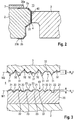
- FIGS. 1 to 3 a mechanical seal assembly 1 according to a preferred embodiment of the invention described in detail.
- FIG. 1 schematically shows the mechanical seal assembly 1 for a power plant feed pump comprising a rotating seal ring 2 and a stationary seal ring 3. Between the two slip rings 2, 3, a sealing gap 4 is formed in a known manner.
- the rotating seal ring 2 is connected via a rotating carrier ring 7 with a shaft sleeve 8.
- first and second pins 10, 11 are provided.
- the shaft sleeve 8 is arranged on a rotating shaft 5.
- the stationary seal ring 3 has a bandage 9 which is fixed on a housing 6 via a stationary carrier ring 12.
- the mechanical seal assembly 1 seals a medium 13 to be conveyed by the power plant feed pump with respect to the environment 14.
- the medium 13 in this embodiment is pure water. Due to the poor electrical conductivity of the pure water and the high sliding speed of the rotating seal ring 2, high electrical potentials of several volts between the slip rings arise. The sliding speeds are usually between 40m / s to 60m / s.
- the rotating seal ring 2 is further provided with a diamond coating 20.
- the entire sliding surface 40 of the rotating seal ring 2 is coated with diamond. This is in detail in the FIGS. 2 and 3 shown.
- the diamond coating 20 is formed both on a sliding surface 40 of the rotating sliding ring 2 and on an outer peripheral region 2 a and an inner peripheral region 2 b. It is on the outside Peripheral region 2a formed in a direction away from the sliding surface 40 direction tapering portion 20a. On the inner peripheral region 2b of the sliding ring, a region 20b tapering away from the sliding surface 40 is formed in the same way. In other words, the diamond coating 20 is also partially provided on the inner and outer peripheries of the sliding ring.
- the rotating carrier ring 7 partially covers the outer tapered portion 20a of the diamond coating. This ensures that the medium 13 located on the outer circumference does not come into contact with the base material of the sliding ring 2.
- the diamond-coated, rotating seal ring can also be used in media that are very aggressive.
- the diamond coating protects the base material of the sliding ring.
- a very good seal between the carrier ring 7 and the tapered region 20 of the diamond coating can be obtained by the tapered region 20a on the outer circumferential region of the sliding ring.
- the diamond coating 20 has been subjected to a polishing step after the coating process, so that in addition to the remaining wells 22 form a plurality of flattened regions 21. So that the diamond layer is electrically conductive, it still has a doping 23 by means of boron.
- the stationary seal ring 3 is made of a carbon composite comprising about 62% by weight of silicon carbide, about 35% by weight of graphite, and a small amount of about 3% by weight of free silicon.
- a sliding surface 41 of the stationary sliding ring 3 has a plurality of protrusions 31 and depressions 32 on the surface of the stationary sliding ring.
- the average roughness R a is drawn.
- the average roughness R a is an arithmetic mean of all deviations of the roughness profile from a middle line.
- the middle line is labeled M1 and the roughness profile of the stationary slip ring 3 with M2.
- the average roughness is marked with R a 1 in the diamond coating 20 and the average roughness R a is marked R a 2 in the stationary seal ring 3.
- the average roughness R a 1 of the diamond coating 20 is significantly smaller than the mean roughness R a 2 of the stationary slip ring 3 made of carbon composite material. This is because the surface of the diamond coating 20 was subjected to a polishing step to form the flattened portions 21. Recesses 22 are provided in each case between the flattened regions 21.
- the stationary slip ring 3 made of carbon composite material was not polished or less polished than the diamond-coated rotating slip ring 2.
- the doping 23 in the diamond coating 20 ensures that no high electrical potential occurs between the two sliding rings during operation, so that no destruction of the sliding surfaces 40, 41 by electrical discharges is possible.
- the mechanical seal assembly 1 according to the invention is particularly suitable for use in feedwater pumps of power plants, where often also a start / stop and constantly changing thermal conditions are present. Nevertheless, the mechanical seal assembly according to the invention has a high robustness and a long service life.
- a supporting portion of the sliding surface 40 of the diamond coating 20 is approximately 60%.
- the carrying component is defined as the quotient of the sum of all flattened regions 21 with respect to the total surface of the sliding surface 40 on the diamond coating 20 (annular surface).
- an average roughness R a 1 of the diamond coating 20 is about 0.03 ⁇ m and an average roughness R a 2 of the sliding surface 41 of the stationary slip ring 3 made of carbon composite is about 0.15 ⁇ m.
- the average roughness R a 2 of the carbon composite material on the stationary slip ring 3 is approximately five times as high as the average roughness R a 1 of the diamond coating 20.
Landscapes
- Engineering & Computer Science (AREA)
- General Engineering & Computer Science (AREA)
- Mechanical Engineering (AREA)
- Mechanical Sealing (AREA)
- Sliding-Contact Bearings (AREA)
- Details Of Reciprocating Pumps (AREA)
Description
- Die vorliegende Erfindung betrifft eine Gleitringdichtungsanordnung mit Gleitringen, welche unterschiedliche Härten und unterschiedliche Anfangsrauheiten aufweisen.
- Gleitringdichtungsanordnungen sind aus dem Stand der Technik in unterschiedlichen Ausgestaltungen bekannt. Beispielsweise ist es bekannt, Gleitringen von Gleitringdichtungen mit einer Diamantbeschichtung zu versehen. (vergleiche
DE 202007016868 U1 ;DE 202010011173 U1 ). Ferner offenbart dieUS 2010/0061676 A1 eine Gleitringdichtung mit einer DLC-Beschichtung mit reinem Wasser als Gleitschmiermittel. Häufig werden im Bereich von Gleitringdichtungsanordnungen jeweils gleiche Gleitringe aus gleichem Material, d.h. mit Gleitflächen mit gleichen Härten, verwendet, da sonst erwartet wird, dass bei Verwendung von Gleitflächen mit großen unterschiedlichen Härten ein hoher Verschleiß am weicheren Gleitring auftreten würde. Von daher werden Gleitringdichtungsanordnungen bisher derart ausgelegt, dass die Gleitpartner die gleiche Härte aufweisen. - Bei der Verwendung von diamantbeschichteten Gleitflächen bei Gleitringen ergibt sich jedoch insbesondere das Problem der hohen Kosten. Allerdings weisen diamantbeschichtete Gleitringe eine sehr hohe Widerstandsfähigkeit gegen Abrieb und damit eine besonders lange Lebensdauer auf.
- Es daher Aufgabe der vorliegenden Erfindung, eine Gleitringdichtungsanordnung bereitzustellen, welche bei einfachem Aufbau und einfacher, kostengünstiger Herstellbarkeit trotzdem die Möglichkeit einer Verwendung einer diamantbeschichteten Gleitfläche ermöglicht.
- Diese Aufgabe wird durch eine Gleitringdichtungsanordnung mit den Merkmalen des Anspruchs 1 gelöst. Die Unteransprüche zeigen bevorzugte Weiterbildungen der Erfindung.
- Die erfindungsgemäße Gleitringdichtungsanordnung umfasst vorzugsweise ein rotierenden Gleitring mit einer ersten Gleitfläche und einen stationären Gleitring mit einer zweiten Gleitfläche. Zwischen den beiden Gleitflächen ist ein Dichtspalt definiert. Hierbei weisen die beiden Gleitflächen unterschiedliche Härten auf, wobei eine der beiden Gleitflächen eine Diamantbeschichtung aufweist und die andere der beiden Gleitflächen aus Kohleverbundwerkstoff ist. Der Kohleverbundwerkstoff ist ein Siliziumcarbid-Graphit-Verbundwerkstoff (SiC-C). Der Kohleverbundwerkstoff ist somit ein Verbundwerkstoff aus Graphit und Silizium, wobei vorzugsweise flüssiges Silizium in einen porösen Graphitkörper eingebracht wird, wobei sich Siliziumcarbid in den freien Poren bildet. Dieser Siliziumcarbid-Bildungsprozess wird so lange fortgesetzt, bis die Poren vollständig mit Siliziumcarbid ausgefüllt sind. Hierbei kann auch noch eine gewisse Restmenge von freiem Silizium im Kohleverbundwerkstoff verbleiben. Ferner ist eine erfindungsgemäße Anfangsrauheit der Gleitflächen mit Diamantbeschichtung kleiner als eine Anfangsrauheit der Gleitfläche aus Kohleverbundwerkstoff. Unter Anfangsrauheit wird dabei eine mittlere Rauheit Ra verstanden, welche die beiden Gleitflächen im neuwertigen Zustand haben. Da die Gleitflächen unterschiedliche Härten aufweisen, ist die Anfangsrauheit der härteren Gleitfläche kleiner gewählt als die Anfangsrauheit der weicheren Gleitfläche aus Kohleverbundwerkstoff.
- Besonders bevorzugt ist die Anfangsrauheit der härteren Gleitfläche mit Diamantbeschichtung um mindestens 50% kleiner als die Anfangsrauheit der Gleitfläche aus Kohleverbundwerkstoff. Hierdurch wird sichergestellt, dass insbesondere auch in einer Einlaufphase der Gleitringdichtungsanordnung keine Beschädigung der weicheren Gleitfläche durch die härtere Gleitfläche erfolgt.
- Weiter bevorzugt ist eine mittlere Rauheit Ra der die Diamantbeschichtung aufweisenden Gleitfläche in einem Bereich 0,01 µm bis 0,06 µm und/oder eine mittlere Rauheit Ra der Gleitfläche aus Kohleverbundwerkstoff ist an einem Bereich von 0,1 µm bis 0,2 µm. Vorzugsweise ist die mittlere Rauheit Ra der Gleitfläche mit Diamantbeschichtung in einem Bereich von 0,02 µm bis 0,05 µm. Weiter bevorzugt ist die mittlere Rauheit der Gleitfläche aus Kohleverbundwerkstoff in einem Bereich von 0,12 µm bis 0,18 µm.
- Weiter bevorzugt weist die Diamantbeschichtung eine Dotierung derart auf, dass die Diamantbeschichtung elektrisch leitfähig ist. Hierdurch ist die elektrisch leitfähige Diamantbeschichtung insbesondere für Gleitringdichtungsanordnungen geeignet, bei denen das abzudichtende Medium Wasser, insbesondere reines Wasser, z.B. im Kraftwerksbereich, ist. Besonders bevorzugt ist die Dotierung der Diamantschicht zur Erzeugung einer elektrisch leitfähigen Diamantschicht eine Bor-Dotierung.
- Besonders bevorzugt ist die Diamantbeschichtung des Gleitrings zusätzlich auch an einem äußeren Umfangsbereich des Gleitrings vorgesehen. Die Diamantbeschichtung ist hierbei besonders bevorzugt nur teilweise am äußeren Umfangsbereich vorgesehen. Weiter bevorzugt verjüngt sich die Diamantbeschichtung am äußeren Umfangsbereich in einer von der Gleitfläche des Gleitrings abgewandten Richtung. Durch das Vorsehen der Diamantbeschichtung am äußeren Umfangsbereich kann insbesondere erreicht werden, dass das Grundmaterial des Gleitrings durch die Diamantbeschichtung vor einem abzudichtenden Medium, beispielsweise reines Wasser, geschützt ist. Weiter bevorzugt ist ein Trägerring vorgesehen, welcher die am äußeren Umfangsbereich des Gleitrings vorgesehene Diamantbeschichtung überdeckt. Hierdurch wird vermieden, dass ein eventuell aggressives Medium an das Grundmaterial, insbesondere SiC, des Gleitrings gelangt.
- Gemäß einer weiteren bevorzugten Ausgestaltung der Erfindung ist die Diamantbeschichtung des Gleitrings zusätzlich auch an einem inneren Umfangsbereich des Gleitrings vorgesehen. Hierbei ist weiter bevorzugt die Diamantbeschichtung nur teilweise am inneren Umfangsbereich ausgebildet und insbesondere verjüngt sich die Diamantbeschichtung am inneren Umfangsbereich in einer von der Gleitfläche abgewandten Richtung.
- Weiter bevorzugt umfasst der Kohleverbundwerkstoff 60 bis 75 Gew.% Siliziumcarbid, 15 bis 40 Gew.% Kohlenstoff und 0,5 bis 10 Gew.% freies Silizium. Besonders bevorzugt umfasst der Kohleverbundwerkstoff 62 Gew.% Siliziumcarbid, 35 Gew.% Kohlenstoff und 3 Ges.% freies Silizium.
- Weiter bevorzugt ist die Gleitfläche der Diamantbeschichtung poliert. Hierdurch wird sichergestellt, dass die Gleitfläche mit Diamantbeschichtung eine geringe Anfangsrauheit als die Gleitfläche aus Kohleverbundwerkstoff aufweist.
- Vorzugsweise weist der rotierende Gleitring die Diamantbeschichtung auf. Durch die Rotation des diamantbeschichteten Gleitrings kann insbesondere ein sehr gleichmäßiges Wärmeausdehnungsverhalten und eine gleichmäßige Kühlung des rotierenden Gleitrings sichergestellt werden, so dass insbesondere wärmebedingte Beschädigungen vermieden werden können.
- Weiter bevorzugt ist ein Traganteil einer Oberfläche der diamantbeschichteten Gleitfläche mindestens größer 45%, insbesondere bevorzugt größer als 50% und weiter bevorzugt größer als 60%. Erfindungsgemäß wird hierbei unter dem Traganteil ein Verhältnis einer Oberfläche, welche die Summe aller glatten Bereiche der Oberfläche umfasst, zu einer Gesamtoberfläche der Gleitfläche. Die glatten Bereiche an der Oberfläche werden beispielsweise durch Polieren oder Feinpolieren der diamantbeschichteten Gleitfläche erhalten. Wenn die gesamte Oberfläche der diamantbeschichteten Gleitfläche poliert werden könnte, so dass ausschließlich ein glatter Bereich an der Oberfläche erhalten würde, wäre der Traganteil 100%.
- Bevorzugt weist der Gleitring mit Diamantbeschichtung an der Diamantbeschichtung eine Vickers-Härte von ca. 10.000 HV und der Gleitring aus Kohleverbundwerkstoff weist im Bereich der harten SiC-Phase eine Vickers-Härte in einem Bereich von 2.000 HV bis 3.000 HV, vorzugsweise 2.500 Hv, auf, und im Bereich der weicheren Graphit-Phase eine Rockwell-Härte in einem Bereich von 50 bis 100 HR15T auf. Weiter bevorzugt weist der diamantbeschichtete Gleitring ein Elastizitätsmodul in einem Bereich von ca. 1.150 N/mm2 auf und der Gleitring aus Kohleverbundwerkstoff ein Elastizitätsmodul in einem Bereich von 1 bis 4 N/mm2 auf. Ferner bevorzugt weist der diamantbeschichtete Gleitring eine Wärmeleitfähigkeit in einem Bereich von ca. 2.000 W/mk auf und der Kohleverbundwerkstoff weist eine Wärmeleitfähigkeit in einem Bereich von 2 bis 85 W/mk auf. Bevorzugt ist eine Dicke der Diamantbeschichtung an der Gleitfläche in einem Bereich von 1 µm bis 20 µm.
- Weiter bevorzugt sind an der Gleitfläche aus Kohleverbundwerkstoff graphithaltige Bereiche ausgebildet. Diese graphithaltigen Bereiche an der Oberfläche der Gleitfläche sind eingerichtet, um freie Partikel, welche sich beispielsweise im abzudichtenden Medium oder in einem Sperrmedium befinden können, aufzunehmen. Durch die graphithaltigen Bereiche an der Oberfläche der Gleitfläche aus Kohleverbundwerkstoff können somit freie Partikel aufgenommen und eingebettet werden, so dass diese keinen Schaden an der gegenüberliegenden Gleitfläche anrichten können. Selbst wenn ein derartiger freier Partikel noch teilweise aus der Gleitfläche aus Kohleverbundwerkstoff hervorstehen würde, tritt keine Beschädigung der Gleitringdichtung auf, da die Gegenfläche die Diamantbeschichtung aufweist, welche durch den nur teilweise in dem weicheren graphithaltigen Bereich aufgenommenen Partikel nicht beschädigt, z. B. geritzt oder dergleichen, werden kann. Die graphithaltigen Bereiche an der Oberfläche der Gleitfläche aus Kohleverbundwerkstoff weisen dabei eine Rockwell-Härte in einem Bereich von 50 bis 100 HR15T auf. Die freien Partikel, welche beispielsweise durch Abrieb oder dergleichen entstehen können, oder auch im abzudichtenden Medium vorhanden sein können, wenn dieses beispielsweise eine Suspension mit harten Partikeln ist, können die sehr harte Diamantbeschichtung nicht beschädigen und werden bei einem Kontakt mit der Diamantbeschichtung gegebenenfalls einfach tiefer in die Gleitfläche aus Kohleverbundwerkstoff eingedrückt oder abgeschert.
- Ferner betrifft die vorliegende Erfindung eine Kraftwerksspeisepumpe umfassend eine erfindungsgemäße Gleitringdichtungsanordnung. Insbesondere bei einer Verwendung der erfindungsgemäßen Gleitringdichtungsanordnung bei Kraftwerksspeisepumpen ergeben sich große Vorteile, da die erfindungsgemäße Gleitringdichtungsanordnung sehr robust ist und eine hohe Einsatzdauer aufweist. Dadurch ist die Gefahr eines Ausfalls der Gleitringdichtungsanordnung insbesondere bei einem Kraftwerksbetrieb, welche üblicherweise auf lange Betriebsdauern zwischen zwei Wartungsintervallen ausgelegt ist, sichergestellt.
- Nachfolgend wird ein bevorzugtes Ausführungsbeispiel der Erfindung unter Bezugnahme auf die begleitende Zeichnung im Detail beschrieben.
- In der Zeichnung ist:
- Fig. 1
- eine schematische Schnittansicht einer Gleitringdichtungsanordnung für eine Kraftwerksspeisepumpe gemäß einem Ausführungsbeispiel der Erfindung,
- Fig. 2
- eine vergrößerte Schnittdarstellung der Gleitringe von
Figur 1 - und Fig. 3
- eine weiter vergrößerte, schematische Schnittansicht der Gleitringe von
Figur 1 und2 - Nachfolgend wird unter Bezugnahme auf die
Figuren 1 bis 3 eine Gleitringdichtungsanordnung 1 gemäß einem bevorzugten Ausführungsbeispiel der Erfindung im Detail beschrieben. -
Figur 1 zeigt schematisch die Gleitringdichtungsanordnung 1 für eine Kraftwerksspeisepumpe umfassend einen rotierenden Gleitring 2 und einen stationären Gleitring 3. Zwischen den beiden Gleitringen 2, 3 ist in bekannter Weise ein Dichtspalt 4 ausgebildet. Der rotierende Gleitring 2 ist über einen rotierenden Trägerring 7 mit einer Wellenhülse 8 verbunden. Zur Drehung und Übertragung von Drehmoment sind hierbei erste und zweite Stifte 10, 11 vorgesehen. Die Wellenhülse 8 ist auf einer rotierenden Welle 5 angeordnet. - Der stationäre Gleitring 3 weist eine Bandage 9 auf, welche über einen stationären Trägerring 12 an einem Gehäuse 6 fixiert ist.
- Die Gleitringdichtungsanordnung 1 dichtet dabei ein durch die Kraftwerksspeisepumpe zu förderndes Medium 13 gegenüber der Umgebung 14 ab. Das Medium 13 in diesem Ausführungsbeispiel ist reines Wasser. Aufgrund der schlechten elektrischen Leitfähigkeit des reinen Wassers und der hohen Gleitgeschwindigkeit des rotierenden Gleitrings 2 ergeben sich hohe elektrische Potentiale von mehreren Volt zwischen den Gleitringen. Die Gleitgeschwindigkeiten liegen üblicherweise zwischen 40m/s bis 60m/s.
- Der rotierende Gleitring 2 ist ferner mit einer Diamantbeschichtung 20 versehen. Hierbei ist die gesamte Gleitfläche 40 des rotierenden Gleitrings 2 mit Diamant beschichtet. Dies ist im Detail in den
Figuren 2 und 3 gezeigt. - Die Diamantbeschichtung 20 ist dabei sowohl an einer Gleitfläche 40 des rotierenden Gleitrings 2 als auch an einem äußeren Umfangsbereich 2a und einem inneren Umfangsbereich 2b ausgebildet. Dabei ist am äußeren Umfangsbereich 2a ein sich in von der Gleitfläche 40 abgewandter Richtung verjüngender Bereich 20a ausgebildet. Am inneren Umfangsbereich 2b des Gleitrings ist in gleicher Weise ein sich in von der Gleitfläche 40 abgewandter Richtung verjüngender Bereich 20b ausgebildet. Mit anderen Worten ist die Diamantbeschichtung 20 auch teilweise am inneren und äußeren Umfang des Gleitrings vorgesehen.
- Weiterhin überdeckt der rotierende Trägerring 7 den äußeren, sich verjüngenden Bereich 20a der Diamantbeschichtung teilweise. Dadurch wird sichergestellt, dass das sich am äußeren Umfang befindliche Medium 13 nicht mit dem Basismaterial des Gleitrings 2 in Kontakt kommt. Hierdurch kann der diamantbeschichtete, rotierende Gleitring auch in Medien verwendet werden, welche sehr aggressiv sind. Die Diamantbeschichtung schützt dabei das Grundmaterial des Gleitrings. Durch den sich verjüngenden Bereich 20a am äußeren Umfangsbereich des Gleitrings kann insbesondere eine sehr gute Abdichtung zwischen dem Trägerring 7 und dem sich verjüngenden Bereich 20 der Diamantbeschichtung erhalten werden.
- Wie weiter aus
Figur 3 ersichtlich ist, ist die Diamantbeschichtung 20 nach dem Beschichtungsvorgang einen Polierschritt unterzogen worden, so dass sich neben den noch vorhandenen Vertiefungen 22 eine Vielzahl von abgeflachten Bereichen 21 bilden. Damit die Diamantschicht elektrisch leitfähig ist, weist sie noch eine Dotierung 23 mittels Bor auf. - Der stationäre Gleitring 3 ist aus einem Kohlenstoff-Verbundwerkstoff hergestellt, welcher ca. 62 Gew.% Siliziumcarbid, ca. 35 Gew.% Graphit und einen kleinen Anteil von ca. 3 Gew.% freiem Silizium umfasst. Eine Gleitfläche 41 des stationären Gleitrings 3 weist an der Oberfläche des stationären Gleitrings eine Vielzahl von Erhebungen 31 und Vertiefungen 32 auf.
- In
Figur 3 ist die mittlere Rauheit Ra eingezeichnet. Die mittlere Rauheit Ra ist dabei ein arithmetischer Mittelwert aller Abweichungen des Rauheitsprofils von einer mittleren Linie. In der Diamantbeschichtung 20 ist die mittlere Linie mit M1 bezeichnet und am Rauheitsprofil des stationären Gleitrings 3 mit M2. Die mittlere Rauheit ist bei der Diamantbeschichtung 20 mit Ra1 gekennzeichnet und die mittlere Rauheit Ra ist beim stationären Gleitring 3 mit Ra2 gekennzeichnet. - Wie dabei ersichtlich ist, ist die mittlere Rauheit Ra1 der Diamantbeschichtung 20 deutlich kleiner als die mittlere Rauheit Ra2 des stationären Gleitrings 3 aus Kohleverbundwerkstoff. Dies ist darin begründet, dass die Oberfläche der Diamantbeschichtung 20 noch einem Polierschritt unterzogen wurde, um die abgeflachten Bereiche 21 zu bilden. Zwischen den abgeflachten Bereichen 21 sind jeweils Vertiefungen 22 vorgesehen. Der stationäre Gleitring 3 aus Kohleverbundwerkstoff wurde nicht oder weniger poliert als der diamantbeschichtete rotierende Gleitring 2.
- Durch die Wahl der unterschiedlichen Materialien für den rotierenden und stationären Gleitring weist der rotierende Gleitring 2 ferner durch die Diamantbeschichtung 20 an seiner Gleitfläche 40 eine größere Härte an der Gleitfläche auf als der aus Kohlenstoff-Material hergestellte stationäre Gleitring 3. Erfindungsgemäß wurde nun durch das reduzierte Rauheitsprofil an der Diamantbeschichtung 20 erreicht, dass ein härterer rotierender Gleitring 2 gegen einen weicheren stationären Gleitring 3 laufen kann, ohne dass es hierbei zu Beschädigungen oder Abrieb oder Verschleiß oder dergleichen am weicheren stationären Gleitring 3 kommt. Durch die geringere mittlere Rauheit Ra1 der härteren Diamantbeschichtung 20 kann somit verhindert werden, dass ein üblicherweise bei einer derartigen Gleitringpaarung zu erwartender erhöhter Verschleiß auftritt.
- Diese auch für einen Fachmann überraschende Erkenntnis ermöglicht es nun, dass Gleitringdichtungsanordnungen eingesetzt werden können, bei denen nur einer der Gleitringe, insbesondere der rotierende Gleitring 2, mit einer Diamantschicht 20 versehen wurde. Der andere, weichere Gleitring weist keine derartige harte Schicht auf, sondern weist eine Gleitfläche aus Kohleverbundwerkstoff auf. Trotzdem kann eine hohe Lebensdauer der Gleitringdichtungsanordnung 1 entsprechend einer Lebensdauer einer Gleitringdichtungsanordnung bei der beide Gleitringe eine Diamantbeschichtung aufweisen, erhalten werden.
- Weiterhin stellt die Dotierung 23 in der Diamantbeschichtung 20 sicher, dass zwischen den beiden Gleitringen im Betrieb kein hohes elektrisches Potential auftritt, so dass keine Zerstörung der Gleitflächen 40, 41 durch elektrische Entladungen möglich sind.
- Somit eignet sich die erfindungsgemäße Gleitringdichtungsanordnung 1 insbesondere zu Verwendung in Speisewasserpumpen von Kraftwerken, bei denen häufig auch ein Anlaufen/Anhalten und sich ständig verändernde thermische Bedingungen vorhanden sind. Trotzdem weist die erfindungsgemäße Gleitringdichtungsanordnung eine hohe Robustheit und eine lange Lebensdauer auf.
- Ein Traganteil der Gleitfläche 40 der Diamantbeschichtung 20 liegt dabei bei ungefähr 60%. Der Traganteil ist dabei derart definiert als Quotient der Summe aller abgeflachten Bereiche 21 gegenüber der Gesamtfläche der Gleitfläche 40 an der Diamantbeschichtung 20 (Ringfläche).
- In diesem Ausführungsbeispiel ist eine mittlere Rauheit Ra1 der Diamantbeschichtung 20 ungefähr 0,03 µm und eine mittlere Rauheit Ra2 der Gleitfläche 41 des stationären Gleitrings 3 aus Kohleverbundwerkstoff ungefähr 0,15 µm. Mit anderen Worten ist die mittlere Rauheit Ra2 des Kohleverbundwerkstoffs am stationären Gleitring 3 ungefähr fünfmal so hoch wie die mittlere Rauheit Ra1 der Diamantbeschichtung 20.
-
- 1
- Gleitringdichtungsanordnung
- 2
- rotierender Gleitring
- 2a
- äußerer Umfangsbereich
- 2b
- innerer Umfangsbereich
- 3
- stationärer Gleitring
- 4
- Dichtspalt
- 5
- Welle
- 6
- Gehäuse
- 7
- rotierender Trägerring
- 8
- Wellenhülse
- 9
- Bandage
- 10
- erster Stift
- 11
- zweiter Stift
- 12
- stationärer Trägerring
- 13
- Medium
- 14
- Umgebung
- 20
- Diamantbeschichtung
- 20a
- sich verjüngender Bereich am Aussenumfang
- 20b
- sich verjüngender Bereich am Innenumfang
- 21
- abgeflachte Bereiche
- 22
- Vertiefungen
- 23
- Bohr-Dotierung
- 31
- Erhebungen
- 32
- Vertiefungen
- 40
- Gleitfläche Diamantbeschichtung
- 41
- Gleitfläche Kohleverbundmaterial
- Ra1
- mittlere Anfangsrauheit der Diamantbeschichtung
- Ra2
- mittlere Anfangsrauheit des Kohleverbundwerkstoffs
- M1, M2
- Bezugslinie
Claims (15)
- Gleitringdichtungsanordnung umfassend:- einen rotierenden Gleitring (2) mit einer ersten Gleitfläche (40) und einen stationären Gleitring (3) mit einer zweiten Gleitfläche (41), welche zwischen sich einen Dichtspalt (4) begrenzen,- wobei die erste und zweite Gleitfläche unterschiedliche Härten aufweisen,- dadurch gekennzeichnet, dass die härtere Gleitfläche eine Diamantbeschichtung (20) aufweist und die weichere Gleitfläche aus Kohleverbundwerkstoff hergestellt ist, wobei der Kohleverbundwerkstoff ein Siliziumcarbid-Graphit-Verbundwerkstoff umfassend Siliziumcarbid, Graphit und freies Silizium ist, und- eine mittlere Anfangsrauheit (Ra1) der ersten Gleitfläche (40) der Diamantbeschichtung (20) kleiner ist als eine mittlere Anfangsrauheit (Ra2) der zweiten Gleitfläche (41) aus Kohleverbundwerkstoff.
- Gleitringdichtungsanordnung nach Anspruch 1, dadurch gekennzeichnet, dass die mittlere Anfangsrauheit (Ra1) des Gleitrings mit Diamantbeschichtung (20) um mindestens 50% kleiner ist als die mittlere Anfangsrauheit (Ra2) des Gleitrings aus Kohleverbundwerkstoff.
- Gleitringdichtungsanordnung nach Anspruch 2, dadurch gekennzeichnet, dass die mittlere Anfangsrauheit (Ra1) der Diamantbeschichtung (20) in einem Bereich von 0,01 µm bis 0,06 µm und/oder das die mittlere Anfangsrauheit (Ra2) der Gleitfläche aus Kohleverbundwerkstoff in einem Bereich von 0,1 µm bis 0,2 µm liegt.
- Gleitringdichtungsanordnung nach einem der vorhergehenden Ansprüche, dadurch gekennzeichnet, dass die Diamantbeschichtung (20) eine Dotierung (23) derart aufweist, dass die Diamantbeschichtung (20) elektrisch leitfähig ist.
- Gleitringdichtungsanordnung nach Anspruch 4, dadurch gekennzeichnet, dass die Dotierung (23) eine Bor-Dotierung ist.
- Gleitringdichtungsanordnung nach einem der vorhergehenden Ansprüche, dadurch gekennzeichnet, dass die Diamantbeschichtung (20) des Gleitrings zusätzlich an einem äußeren Umfangsbereich (20a) des Gleitrings vorgesehen ist.
- Gleitringdichtungsanordnung nach Anspruch 6, dadurch gekennzeichnet, dass die Diamantbeschichtung (20) nur teilweise am äußeren Umfangsbereich (2a) des Gleitrings vorgesehen ist und insbesondere die Diamantbeschichtung am äußeren Umfangsbereich (2a) einen sich verjüngenden Bereich (20a) aufweist.
- Gleitringdichtungsanordnung nach Anspruch 6 oder 7, dadurch gekennzeichnet, dass ein Trägerring (7) die am äußeren Umfangsbereich (2a) des Gleitrings (2) vorgesehene Diamantbeschichtung zumindest teilweise überdeckt.
- Gleitringdichtungsanordnung nach einem der Ansprüche 6 bis 8, dadurch gekennzeichnet, dass die Diamantbeschichtung des Gleitrings zusätzlich an einem inneren Umfangsbereich (2b) des Gleitrings vorgesehen ist.
- Gleitringdichtungsanordnung nach einem der vorhergehenden Ansprüche, dadurch gekennzeichnet, dass die Gleitfläche (40) der Diamantbeschichtung (20) poliert ist.
- Gleitringdichtungsanordnung nach einem der vorhergehenden Ansprüche, dadurch gekennzeichnet, dass der rotierende Gleitring (2) die Diamantbeschichtung (20) aufinreist.
- Gleitringdichtungsanordnung nach einem der vorhergehenden Ansprüche, dadurch gekennzeichnet, dass die Gleitfläche (40) der Diamantbeschichtung (20) ein Traganteil von ≥ 50% aufweist.
- Gleitringdichtungsanordnung nach einem der vorhergehenden Ansprüche, dadurch gekennzeichnet, dass der Kohleverbundwerkstoff 60 bis 75 Gew.% Silizumcarbid, 15 bis 40 Gew.% Kohlenstoff und 0,5 bis 10 Gew.% freies Silizium umfasst.
- Gleitringdichtungsanordnung nach einem der vorhergehenden Ansprüche, dadurch gekennzeichnet dass an der Gleitfläche (41) aus Kohleverbundwerkstoff graphithaltige Bereiche , insbesondere mit einer Rockwell-Härte von 50 bis 100 HR15T, ausgebildet sind, welche zur Aufnahme von freien Partikeln eingerichtet sind.
- Kraftwerksspeisepumpe umfassend eine Gleitringdichtungsanordnung nach einem der vorhergehenden Ansprüche.
Priority Applications (1)
| Application Number | Priority Date | Filing Date | Title |
|---|---|---|---|
| PL14709278T PL2981746T3 (pl) | 2013-04-04 | 2014-03-11 | Układ uszczelnienia pierścieniami ślizgowymi o powierzchniach ślizgowych różnej twardości |
Applications Claiming Priority (2)
| Application Number | Priority Date | Filing Date | Title |
|---|---|---|---|
| DE102013005926.7A DE102013005926B4 (de) | 2013-04-04 | 2013-04-04 | Gleitringdichtungsanordnung mit unterschiedlich harten Gleitflächen |
| PCT/EP2014/054658 WO2014161704A1 (de) | 2013-04-04 | 2014-03-11 | Gleitringdichtungsanordnung mit unterschiedlich harten gleitflächen |
Publications (2)
| Publication Number | Publication Date |
|---|---|
| EP2981746A1 EP2981746A1 (de) | 2016-02-10 |
| EP2981746B1 true EP2981746B1 (de) | 2017-05-10 |
Family
ID=50241424
Family Applications (1)
| Application Number | Title | Priority Date | Filing Date |
|---|---|---|---|
| EP14709278.7A Active EP2981746B1 (de) | 2013-04-04 | 2014-03-11 | Gleitringdichtungsanordnung mit unterschiedlich harten gleitflächen |
Country Status (11)
| Country | Link |
|---|---|
| US (1) | US9841107B2 (de) |
| EP (1) | EP2981746B1 (de) |
| JP (1) | JP6046858B2 (de) |
| KR (1) | KR101808126B1 (de) |
| CN (1) | CN105074299B (de) |
| AU (1) | AU2014247283B2 (de) |
| DE (1) | DE102013005926B4 (de) |
| PL (1) | PL2981746T3 (de) |
| RU (1) | RU2614556C1 (de) |
| WO (1) | WO2014161704A1 (de) |
| ZA (1) | ZA201506624B (de) |
Families Citing this family (43)
| Publication number | Priority date | Publication date | Assignee | Title |
|---|---|---|---|---|
| JP6470596B2 (ja) * | 2015-03-09 | 2019-02-13 | 日本ピラー工業株式会社 | スラリ液用メカニカルシール |
| JP6422378B2 (ja) * | 2015-03-09 | 2018-11-14 | 日本ピラー工業株式会社 | 端面接触形メカニカルシール |
| JP6490992B2 (ja) * | 2015-03-09 | 2019-03-27 | 日本ピラー工業株式会社 | ロータリジョイント |
| JP6446294B2 (ja) * | 2015-03-09 | 2018-12-26 | 日本ピラー工業株式会社 | ダブルメカニカルシール |
| JP6452503B2 (ja) * | 2015-03-09 | 2019-01-16 | 日本ピラー工業株式会社 | ドライコンタクトシール |
| JP6471006B2 (ja) * | 2015-03-09 | 2019-02-13 | 日本ピラー工業株式会社 | 遊動環型メカニカルシール |
| JP6593863B2 (ja) * | 2015-03-09 | 2019-10-23 | 日本ピラー工業株式会社 | ロータリジョイント |
| JP6490993B2 (ja) * | 2015-03-09 | 2019-03-27 | 日本ピラー工業株式会社 | 多流路形ロータリジョイント |
| JP6490994B2 (ja) * | 2015-03-09 | 2019-03-27 | 日本ピラー工業株式会社 | 多流路形ロータリジョイント |
| JP6423291B2 (ja) * | 2015-03-09 | 2018-11-14 | 日本ピラー工業株式会社 | 多分割型メカニカルシール |
| JP6446295B2 (ja) * | 2015-03-09 | 2018-12-26 | 日本ピラー工業株式会社 | 分割型メカニカルシール |
| JP6446296B2 (ja) * | 2015-03-09 | 2018-12-26 | 日本ピラー工業株式会社 | 非接触式ガスシール |
| WO2016167170A1 (ja) | 2015-04-16 | 2016-10-20 | イーグル工業株式会社 | 摺動部品 |
| EP3093365B1 (de) * | 2015-05-14 | 2019-07-03 | Microtecnica S.r.l. | Gleitringdichtung |
| DE102015211223B3 (de) | 2015-06-18 | 2016-07-21 | Eagleburgmann Germany Gmbh & Co. Kg | Gleitringdichtungsanordnung mit Ausrücksicherung |
| JP2017227260A (ja) * | 2016-06-22 | 2017-12-28 | 株式会社酉島製作所 | 耐摩耗部材およびこれを用いたメカニカルシール |
| JP6708496B2 (ja) * | 2016-07-01 | 2020-06-10 | 日本ピラー工業株式会社 | メカニカルシール |
| JP6744160B2 (ja) * | 2016-07-13 | 2020-08-19 | 日本ピラー工業株式会社 | メカニカルシール |
| JP6356752B2 (ja) * | 2016-09-08 | 2018-07-11 | 日本ピラー工業株式会社 | メカニカルシール |
| DE102016223636B3 (de) * | 2016-11-29 | 2018-05-17 | Eagleburgmann Germany Gmbh & Co. Kg | Gleitringdichtungsanordnung mit minimaler Leckage |
| EP3601854B1 (de) * | 2017-03-20 | 2022-09-07 | Flowserve Management Company | Mechanische stosswellendichtung |
| US11473679B2 (en) | 2017-03-20 | 2022-10-18 | Flowserve Management Company | Shock wave mechanical seal |
| JP2018169017A (ja) * | 2017-03-30 | 2018-11-01 | 日本ピラー工業株式会社 | 密封環 |
| RU2646063C1 (ru) * | 2017-04-06 | 2018-03-01 | Акционерное общество "Уральский научно-исследовательский институт композиционных материалов" | Торцовое уплотнение из композиционного материала на основе углерод-карбидокремниевой матрицы, армированной углеродными волокнами, и способ его изготовления |
| DE102017108744A1 (de) * | 2017-04-24 | 2018-10-25 | Ews Weigele Gmbh & Co. Kg | Dichtungseinheit |
| JP7154692B2 (ja) * | 2017-07-04 | 2022-10-18 | イーグル工業株式会社 | メカニカルシール |
| JP2019027466A (ja) * | 2017-07-27 | 2019-02-21 | 日本ピラー工業株式会社 | メカニカルシール |
| DE102017214132B4 (de) * | 2017-08-14 | 2020-03-26 | Eagleburgmann Germany Gmbh & Co. Kg | Gleitringdichtungsanordnung sowie Gleitringdichtungs-Baukasten |
| KR101944385B1 (ko) * | 2017-09-14 | 2019-02-01 | 김동호 | 메커니컬 실 |
| GB201721615D0 (en) | 2017-12-21 | 2018-02-07 | Koninklijke Nederlandse Akademie Van Wetenschappen | Immune cell organoid co-cultures |
| DE102018201141B4 (de) * | 2018-01-25 | 2023-01-19 | Eagleburgmann Germany Gmbh & Co. Kg | Gebrochener Gleitring sowie Gleitringdichtung mit derartigem Gleitring |
| JP6404521B1 (ja) * | 2018-06-13 | 2018-10-10 | 日本ピラー工業株式会社 | メカニカルシール |
| JP6427295B1 (ja) * | 2018-09-12 | 2018-11-21 | 日本ピラー工業株式会社 | メカニカルシール |
| DE102018124257A1 (de) * | 2018-10-01 | 2020-04-02 | Carl Freudenberg Kg | Dichtelement |
| JP7138035B2 (ja) * | 2018-12-14 | 2022-09-15 | 京セラ株式会社 | 電解研磨用導電性部材および摺動リング |
| DE102019202109B4 (de) * | 2019-02-18 | 2021-01-21 | Eagleburgmann Germany Gmbh & Co. Kg | Druckumkehr geeignete Gleitringdichtungsanordnung |
| US11506217B2 (en) | 2020-01-21 | 2022-11-22 | John Crane Uk Limited | Porous carbon containment or separation seal |
| DE102020110776B4 (de) | 2020-04-21 | 2022-07-07 | Eagleburgmann Germany Gmbh & Co. Kg | Gleitringdichtungsanordnung mit Verschleißoptimierung |
| DE102020003140A1 (de) * | 2020-05-26 | 2021-12-02 | KSB SE & Co. KGaA | Kreiselpumpe mit mindestens einer hydrodynamischen Gleitlageranordnung |
| DE102020003268A1 (de) | 2020-05-29 | 2021-12-02 | KSB SE & Co. KGaA | Kreiselpumpe mit einer Gleitringdichtungsanordnung |
| DE102021127005A1 (de) * | 2021-10-19 | 2023-04-20 | Eagleburgmann Germany Gmbh & Co. Kg | Gleitring mit Verschleiß-Messeinrichtung sowie Gleitringdichtungsanordnung mit derartigem Gleitring |
| DE102023103127A1 (de) * | 2023-02-09 | 2024-08-14 | Eagleburgmann Germany Gmbh & Co. Kg | Gleitringdichtungsanordnung |
| US12577677B2 (en) * | 2024-02-02 | 2026-03-17 | Honeywell International Inc. | Abrasion-resistant coatings for high-temperature substrates |
Family Cites Families (22)
| Publication number | Priority date | Publication date | Assignee | Title |
|---|---|---|---|---|
| SU1320022A1 (ru) * | 1978-02-28 | 1987-06-30 | Предприятие П/Я М-5409 | Способ получени антифрикционных материалов |
| SU1071849A1 (ru) * | 1982-11-29 | 1984-02-07 | Дзержинский филиал Ленинградского научно-исследовательского и конструкторского института химического машиностроения | Торцовое уплотнение |
| JPS59102872A (ja) | 1982-12-06 | 1984-06-14 | 日本特殊陶業株式会社 | 炭化珪素.黒鉛複合焼結体の製造方法 |
| US5909879A (en) * | 1993-03-09 | 1999-06-08 | Norton Company | Diamond film coating for mating parts |
| DE69503411T2 (de) * | 1994-03-30 | 1998-11-19 | Cummins Engine Co Inc | Dichtung zum mechanischen Abdichten einer Kühlmittelpumpe einer Dieselbrennkraftmaschine und Verfahren zu deren Herstellung |
| US6241760B1 (en) * | 1996-04-26 | 2001-06-05 | G. David Jang | Intravascular stent |
| RU2152550C1 (ru) * | 1996-05-05 | 2000-07-10 | Иркутский филиал Института лазерной физики СО РАН | Торцовое уплотнение и способ его изготовления |
| DE19922665B4 (de) | 1999-05-18 | 2005-05-12 | Fraunhofer-Gesellschaft zur Förderung der angewandten Forschung e.V. | Verfahren zur Herstellung von einer extrem glatten feinkristallinen Diamantschicht auf dreidimensionalen Grundkörpern und deren Verwendung |
| US20040222594A1 (en) * | 2003-05-08 | 2004-11-11 | Dresser-Rand Company | Oil film sealing device for a rotating shaft |
| JP4711214B2 (ja) * | 2005-01-11 | 2011-06-29 | 日産自動車株式会社 | メカニカルシール機構 |
| EP1853746B1 (de) * | 2005-03-02 | 2012-12-19 | Ebara Corporation | Verwendung einer diamantbeschichteten lager- oder dichtungsstruktur |
| JP2006275286A (ja) * | 2005-03-02 | 2006-10-12 | Ebara Corp | ダイヤモンド被覆軸受又はシール構造並びにその軸受又はシール構造を備えた流体機械 |
| DE202006006425U1 (de) * | 2006-04-21 | 2006-06-29 | Burgmann Industries Gmbh & Co. Kg | Bauteil, insbesondere Gleitring einer Gleitringdichtungsanordnung |
| CN201013897Y (zh) * | 2007-02-02 | 2008-01-30 | 宁波东联密封件有限公司 | 通用机械密封件 |
| CN201050598Y (zh) * | 2007-03-24 | 2008-04-23 | 虞培清 | 一种专用机械密封 |
| US20100061676A1 (en) | 2007-04-20 | 2010-03-11 | Ebara Corporation | bearing system or a sealing system using a carbon based sliding member |
| JP5273337B2 (ja) * | 2007-06-01 | 2013-08-28 | 神奈川県 | 低摩擦摺動部材 |
| DE202007016868U1 (de) * | 2007-12-04 | 2008-02-14 | Burgmann Industries Gmbh & Co. Kg | Gleitring einer Gleitringdichtungsanordnung |
| JP4704453B2 (ja) * | 2008-07-16 | 2011-06-15 | 株式会社プラズマイオンアシスト | ダイヤモンドライクカーボン製造装置、製造方法及び工業製品 |
| DE202008009842U1 (de) * | 2008-07-22 | 2008-09-18 | Burgmann Industries Gmbh & Co. Kg | Gleitringdichtungsanordnung mit Filterelement |
| DE202010011173U1 (de) * | 2010-08-09 | 2011-12-22 | Eagleburgmann Germany Gmbh & Co. Kg | Gleitring mit verbesserten Einlaufeigenschaften |
| DE102010054875B4 (de) * | 2010-12-17 | 2012-10-31 | Eagleburgmann Germany Gmbh & Co. Kg | Reibungsarmer Gleitring mit kostengünstiger Diamantbeschichtung |
-
2013
- 2013-04-04 DE DE102013005926.7A patent/DE102013005926B4/de not_active Expired - Fee Related
-
2014
- 2014-03-11 AU AU2014247283A patent/AU2014247283B2/en active Active
- 2014-03-11 WO PCT/EP2014/054658 patent/WO2014161704A1/de not_active Ceased
- 2014-03-11 KR KR1020157027393A patent/KR101808126B1/ko active Active
- 2014-03-11 JP JP2016505749A patent/JP6046858B2/ja active Active
- 2014-03-11 US US14/780,662 patent/US9841107B2/en active Active
- 2014-03-11 EP EP14709278.7A patent/EP2981746B1/de active Active
- 2014-03-11 CN CN201480018876.7A patent/CN105074299B/zh active Active
- 2014-03-11 PL PL14709278T patent/PL2981746T3/pl unknown
- 2014-03-11 RU RU2015147178A patent/RU2614556C1/ru active
-
2015
- 2015-09-08 ZA ZA2015/06624A patent/ZA201506624B/en unknown
Also Published As
| Publication number | Publication date |
|---|---|
| DE102013005926A1 (de) | 2014-10-23 |
| KR20150127647A (ko) | 2015-11-17 |
| PL2981746T3 (pl) | 2017-10-31 |
| EP2981746A1 (de) | 2016-02-10 |
| WO2014161704A1 (de) | 2014-10-09 |
| JP2016516954A (ja) | 2016-06-09 |
| AU2014247283A1 (en) | 2015-10-29 |
| CN105074299B (zh) | 2017-04-26 |
| KR101808126B1 (ko) | 2017-12-13 |
| CN105074299A (zh) | 2015-11-18 |
| ZA201506624B (en) | 2017-08-30 |
| DE102013005926A8 (de) | 2014-12-18 |
| US9841107B2 (en) | 2017-12-12 |
| AU2014247283B2 (en) | 2016-05-12 |
| DE102013005926B4 (de) | 2015-12-03 |
| JP6046858B2 (ja) | 2016-12-21 |
| RU2614556C1 (ru) | 2017-03-28 |
| US20160053895A1 (en) | 2016-02-25 |
Similar Documents
| Publication | Publication Date | Title |
|---|---|---|
| DE102013005926B4 (de) | Gleitringdichtungsanordnung mit unterschiedlich harten Gleitflächen | |
| EP2603618B1 (de) | Gleitring mit verbesserten einlaufeigenschaften | |
| EP2029919B1 (de) | Gleitring einer gleitringdichtungsanordnung | |
| EP1071896A1 (de) | Dichtungselement für eine gleitringdichtungsanordnung | |
| DE112007001500T5 (de) | Lageranordnung mit einer elastischen Dichtung | |
| DE202018107062U1 (de) | Radialwellen-Dichtungsvorrichtung | |
| EP3492785B1 (de) | Dichtring und dichtungsanordnung, die einen solchen dichtring umfasst | |
| DE112017004516T5 (de) | Mechanische abdichtung | |
| EP2626578A1 (de) | Gleitlageranordnung | |
| EP1526310A1 (de) | Dichtungsanordnung | |
| EP2466148B1 (de) | Dichtungsanordnung für Kreiselpumpen | |
| EP4419818B1 (de) | Gleitring mit verschleiss-messeinrichtung sowie gleitringdichtungsanordnung mit derartigem gleitring | |
| EP3469237B1 (de) | Gleitringdichtungsanordnung sowie bohrloch-fördervorrichtung | |
| DE102016118052A1 (de) | Wälzlager, Dichtelement, Windkraftanlage und Verfahren zum Betrieb eines Wälzlagers | |
| WO2016119787A1 (de) | Gleitlageranordnung für eine mit einer umlaufenden radialkraft belasteten welle | |
| DE102006058945A1 (de) | Dichtungselement für rotierbare Teile mit Traktrix-Form | |
| DE102016204458B4 (de) | Wälzlager, Exzenterantrieb mit einem solchen Wälzlager sowie Radialkolbenpumpe und deren Verwendung | |
| DE102013225398A1 (de) | Lagerbauteil mit Diamantinnenbeschichtung | |
| WO2010006685A1 (de) | Gleitringdichtungsanordnung | |
| DE102014203569B3 (de) | Gleitringdichtungsanordnung mit OH-Radikal-Erzeugungsvorrichtung | |
| DE102016200821B3 (de) | Gleitringdichtungsanordnung mit rückseitiger Abdichtung | |
| EP2221515A1 (de) | Gleitringdichtung und Verfahren zur Herstellung einer solchen Gleitringdichtung | |
| DE102015215303B4 (de) | Temperaturkompensationsring sowie Lagerring mit dem Temperaturkompensationsring | |
| DE102024116444A1 (de) | Gleitring und Gehäuse sowie Gleitringdichtung | |
| DE102023132984A1 (de) | Wälzlageranordnung und Windkraftanlage |
Legal Events
| Date | Code | Title | Description |
|---|---|---|---|
| PUAI | Public reference made under article 153(3) epc to a published international application that has entered the european phase |
Free format text: ORIGINAL CODE: 0009012 |
|
| 17P | Request for examination filed |
Effective date: 20150910 |
|
| AK | Designated contracting states |
Kind code of ref document: A1 Designated state(s): AL AT BE BG CH CY CZ DE DK EE ES FI FR GB GR HR HU IE IS IT LI LT LU LV MC MK MT NL NO PL PT RO RS SE SI SK SM TR |
|
| AX | Request for extension of the european patent |
Extension state: BA ME |
|
| DAX | Request for extension of the european patent (deleted) | ||
| GRAP | Despatch of communication of intention to grant a patent |
Free format text: ORIGINAL CODE: EPIDOSNIGR1 |
|
| INTG | Intention to grant announced |
Effective date: 20170120 |
|
| GRAS | Grant fee paid |
Free format text: ORIGINAL CODE: EPIDOSNIGR3 |
|
| GRAA | (expected) grant |
Free format text: ORIGINAL CODE: 0009210 |
|
| AK | Designated contracting states |
Kind code of ref document: B1 Designated state(s): AL AT BE BG CH CY CZ DE DK EE ES FI FR GB GR HR HU IE IS IT LI LT LU LV MC MK MT NL NO PL PT RO RS SE SI SK SM TR |
|
| REG | Reference to a national code |
Ref country code: GB Ref legal event code: FG4D Free format text: NOT ENGLISH |
|
| REG | Reference to a national code |
Ref country code: AT Ref legal event code: REF Ref document number: 892696 Country of ref document: AT Kind code of ref document: T Effective date: 20170515 Ref country code: CH Ref legal event code: EP |
|
| REG | Reference to a national code |
Ref country code: IE Ref legal event code: FG4D Free format text: LANGUAGE OF EP DOCUMENT: GERMAN |
|
| REG | Reference to a national code |
Ref country code: DE Ref legal event code: R096 Ref document number: 502014003770 Country of ref document: DE |
|
| REG | Reference to a national code |
Ref country code: NL Ref legal event code: FP |
|
| REG | Reference to a national code |
Ref country code: LT Ref legal event code: MG4D |
|
| PG25 | Lapsed in a contracting state [announced via postgrant information from national office to epo] |
Ref country code: GR Free format text: LAPSE BECAUSE OF FAILURE TO SUBMIT A TRANSLATION OF THE DESCRIPTION OR TO PAY THE FEE WITHIN THE PRESCRIBED TIME-LIMIT Effective date: 20170811 Ref country code: ES Free format text: LAPSE BECAUSE OF FAILURE TO SUBMIT A TRANSLATION OF THE DESCRIPTION OR TO PAY THE FEE WITHIN THE PRESCRIBED TIME-LIMIT Effective date: 20170510 Ref country code: HR Free format text: LAPSE BECAUSE OF FAILURE TO SUBMIT A TRANSLATION OF THE DESCRIPTION OR TO PAY THE FEE WITHIN THE PRESCRIBED TIME-LIMIT Effective date: 20170510 Ref country code: FI Free format text: LAPSE BECAUSE OF FAILURE TO SUBMIT A TRANSLATION OF THE DESCRIPTION OR TO PAY THE FEE WITHIN THE PRESCRIBED TIME-LIMIT Effective date: 20170510 Ref country code: LT Free format text: LAPSE BECAUSE OF FAILURE TO SUBMIT A TRANSLATION OF THE DESCRIPTION OR TO PAY THE FEE WITHIN THE PRESCRIBED TIME-LIMIT Effective date: 20170510 Ref country code: NO Free format text: LAPSE BECAUSE OF FAILURE TO SUBMIT A TRANSLATION OF THE DESCRIPTION OR TO PAY THE FEE WITHIN THE PRESCRIBED TIME-LIMIT Effective date: 20170810 |
|
| PG25 | Lapsed in a contracting state [announced via postgrant information from national office to epo] |
Ref country code: RS Free format text: LAPSE BECAUSE OF FAILURE TO SUBMIT A TRANSLATION OF THE DESCRIPTION OR TO PAY THE FEE WITHIN THE PRESCRIBED TIME-LIMIT Effective date: 20170510 Ref country code: LV Free format text: LAPSE BECAUSE OF FAILURE TO SUBMIT A TRANSLATION OF THE DESCRIPTION OR TO PAY THE FEE WITHIN THE PRESCRIBED TIME-LIMIT Effective date: 20170510 Ref country code: SE Free format text: LAPSE BECAUSE OF FAILURE TO SUBMIT A TRANSLATION OF THE DESCRIPTION OR TO PAY THE FEE WITHIN THE PRESCRIBED TIME-LIMIT Effective date: 20170510 Ref country code: IS Free format text: LAPSE BECAUSE OF FAILURE TO SUBMIT A TRANSLATION OF THE DESCRIPTION OR TO PAY THE FEE WITHIN THE PRESCRIBED TIME-LIMIT Effective date: 20170910 Ref country code: BG Free format text: LAPSE BECAUSE OF FAILURE TO SUBMIT A TRANSLATION OF THE DESCRIPTION OR TO PAY THE FEE WITHIN THE PRESCRIBED TIME-LIMIT Effective date: 20170810 |
|
| PG25 | Lapsed in a contracting state [announced via postgrant information from national office to epo] |
Ref country code: DK Free format text: LAPSE BECAUSE OF FAILURE TO SUBMIT A TRANSLATION OF THE DESCRIPTION OR TO PAY THE FEE WITHIN THE PRESCRIBED TIME-LIMIT Effective date: 20170510 Ref country code: SK Free format text: LAPSE BECAUSE OF FAILURE TO SUBMIT A TRANSLATION OF THE DESCRIPTION OR TO PAY THE FEE WITHIN THE PRESCRIBED TIME-LIMIT Effective date: 20170510 Ref country code: CZ Free format text: LAPSE BECAUSE OF FAILURE TO SUBMIT A TRANSLATION OF THE DESCRIPTION OR TO PAY THE FEE WITHIN THE PRESCRIBED TIME-LIMIT Effective date: 20170510 Ref country code: EE Free format text: LAPSE BECAUSE OF FAILURE TO SUBMIT A TRANSLATION OF THE DESCRIPTION OR TO PAY THE FEE WITHIN THE PRESCRIBED TIME-LIMIT Effective date: 20170510 Ref country code: RO Free format text: LAPSE BECAUSE OF FAILURE TO SUBMIT A TRANSLATION OF THE DESCRIPTION OR TO PAY THE FEE WITHIN THE PRESCRIBED TIME-LIMIT Effective date: 20170510 |
|
| REG | Reference to a national code |
Ref country code: DE Ref legal event code: R097 Ref document number: 502014003770 Country of ref document: DE |
|
| PG25 | Lapsed in a contracting state [announced via postgrant information from national office to epo] |
Ref country code: SM Free format text: LAPSE BECAUSE OF FAILURE TO SUBMIT A TRANSLATION OF THE DESCRIPTION OR TO PAY THE FEE WITHIN THE PRESCRIBED TIME-LIMIT Effective date: 20170510 |
|
| PLBE | No opposition filed within time limit |
Free format text: ORIGINAL CODE: 0009261 |
|
| STAA | Information on the status of an ep patent application or granted ep patent |
Free format text: STATUS: NO OPPOSITION FILED WITHIN TIME LIMIT |
|
| REG | Reference to a national code |
Ref country code: FR Ref legal event code: PLFP Year of fee payment: 5 |
|
| 26N | No opposition filed |
Effective date: 20180213 |
|
| PG25 | Lapsed in a contracting state [announced via postgrant information from national office to epo] |
Ref country code: SI Free format text: LAPSE BECAUSE OF FAILURE TO SUBMIT A TRANSLATION OF THE DESCRIPTION OR TO PAY THE FEE WITHIN THE PRESCRIBED TIME-LIMIT Effective date: 20170510 |
|
| PG25 | Lapsed in a contracting state [announced via postgrant information from national office to epo] |
Ref country code: MT Free format text: LAPSE BECAUSE OF FAILURE TO SUBMIT A TRANSLATION OF THE DESCRIPTION OR TO PAY THE FEE WITHIN THE PRESCRIBED TIME-LIMIT Effective date: 20170510 |
|
| REG | Reference to a national code |
Ref country code: CH Ref legal event code: PL |
|
| PG25 | Lapsed in a contracting state [announced via postgrant information from national office to epo] |
Ref country code: MC Free format text: LAPSE BECAUSE OF FAILURE TO SUBMIT A TRANSLATION OF THE DESCRIPTION OR TO PAY THE FEE WITHIN THE PRESCRIBED TIME-LIMIT Effective date: 20170510 |
|
| REG | Reference to a national code |
Ref country code: BE Ref legal event code: MM Effective date: 20180331 |
|
| REG | Reference to a national code |
Ref country code: IE Ref legal event code: MM4A |
|
| PG25 | Lapsed in a contracting state [announced via postgrant information from national office to epo] |
Ref country code: LU Free format text: LAPSE BECAUSE OF NON-PAYMENT OF DUE FEES Effective date: 20180311 |
|
| PG25 | Lapsed in a contracting state [announced via postgrant information from national office to epo] |
Ref country code: IE Free format text: LAPSE BECAUSE OF NON-PAYMENT OF DUE FEES Effective date: 20180311 |
|
| PG25 | Lapsed in a contracting state [announced via postgrant information from national office to epo] |
Ref country code: BE Free format text: LAPSE BECAUSE OF NON-PAYMENT OF DUE FEES Effective date: 20180331 Ref country code: LI Free format text: LAPSE BECAUSE OF NON-PAYMENT OF DUE FEES Effective date: 20180331 Ref country code: CH Free format text: LAPSE BECAUSE OF NON-PAYMENT OF DUE FEES Effective date: 20180331 |
|
| PG25 | Lapsed in a contracting state [announced via postgrant information from national office to epo] |
Ref country code: TR Free format text: LAPSE BECAUSE OF FAILURE TO SUBMIT A TRANSLATION OF THE DESCRIPTION OR TO PAY THE FEE WITHIN THE PRESCRIBED TIME-LIMIT Effective date: 20170510 |
|
| PG25 | Lapsed in a contracting state [announced via postgrant information from national office to epo] |
Ref country code: PT Free format text: LAPSE BECAUSE OF FAILURE TO SUBMIT A TRANSLATION OF THE DESCRIPTION OR TO PAY THE FEE WITHIN THE PRESCRIBED TIME-LIMIT Effective date: 20170510 |
|
| PG25 | Lapsed in a contracting state [announced via postgrant information from national office to epo] |
Ref country code: CY Free format text: LAPSE BECAUSE OF FAILURE TO SUBMIT A TRANSLATION OF THE DESCRIPTION OR TO PAY THE FEE WITHIN THE PRESCRIBED TIME-LIMIT Effective date: 20170510 Ref country code: HU Free format text: LAPSE BECAUSE OF FAILURE TO SUBMIT A TRANSLATION OF THE DESCRIPTION OR TO PAY THE FEE WITHIN THE PRESCRIBED TIME-LIMIT; INVALID AB INITIO Effective date: 20140311 Ref country code: MK Free format text: LAPSE BECAUSE OF NON-PAYMENT OF DUE FEES Effective date: 20170510 |
|
| PG25 | Lapsed in a contracting state [announced via postgrant information from national office to epo] |
Ref country code: AL Free format text: LAPSE BECAUSE OF FAILURE TO SUBMIT A TRANSLATION OF THE DESCRIPTION OR TO PAY THE FEE WITHIN THE PRESCRIBED TIME-LIMIT Effective date: 20170510 |
|
| REG | Reference to a national code |
Ref country code: AT Ref legal event code: MM01 Ref document number: 892696 Country of ref document: AT Kind code of ref document: T Effective date: 20190311 |
|
| PG25 | Lapsed in a contracting state [announced via postgrant information from national office to epo] |
Ref country code: AT Free format text: LAPSE BECAUSE OF NON-PAYMENT OF DUE FEES Effective date: 20190311 |
|
| P01 | Opt-out of the competence of the unified patent court (upc) registered |
Effective date: 20230426 |
|
| PGFP | Annual fee paid to national office [announced via postgrant information from national office to epo] |
Ref country code: IT Payment date: 20250331 Year of fee payment: 12 |
|
| PGFP | Annual fee paid to national office [announced via postgrant information from national office to epo] |
Ref country code: GB Payment date: 20260324 Year of fee payment: 13 |
|
| PGFP | Annual fee paid to national office [announced via postgrant information from national office to epo] |
Ref country code: DE Payment date: 20260320 Year of fee payment: 13 |
|
| PGFP | Annual fee paid to national office [announced via postgrant information from national office to epo] |
Ref country code: NL Payment date: 20260323 Year of fee payment: 13 |
|
| PGFP | Annual fee paid to national office [announced via postgrant information from national office to epo] |
Ref country code: FR Payment date: 20260324 Year of fee payment: 13 |
|
| PGFP | Annual fee paid to national office [announced via postgrant information from national office to epo] |
Ref country code: PL Payment date: 20260226 Year of fee payment: 13 |