EP2981394B1 - Lighting device - Google Patents
Lighting device Download PDFInfo
- Publication number
- EP2981394B1 EP2981394B1 EP14778738.6A EP14778738A EP2981394B1 EP 2981394 B1 EP2981394 B1 EP 2981394B1 EP 14778738 A EP14778738 A EP 14778738A EP 2981394 B1 EP2981394 B1 EP 2981394B1
- Authority
- EP
- European Patent Office
- Prior art keywords
- tool
- housing
- distal end
- lighting device
- protrusions
- Prior art date
- Legal status (The legal status is an assumption and is not a legal conclusion. Google has not performed a legal analysis and makes no representation as to the accuracy of the status listed.)
- Active
Links
- 238000009434 installation Methods 0.000 claims description 7
- 239000000463 material Substances 0.000 description 21
- 230000008901 benefit Effects 0.000 description 11
- 238000004891 communication Methods 0.000 description 5
- 238000005286 illumination Methods 0.000 description 5
- 230000014759 maintenance of location Effects 0.000 description 5
- 230000006835 compression Effects 0.000 description 4
- 238000007906 compression Methods 0.000 description 4
- 239000013536 elastomeric material Substances 0.000 description 4
- 230000000694 effects Effects 0.000 description 3
- 239000012530 fluid Substances 0.000 description 3
- 230000007246 mechanism Effects 0.000 description 3
- 229910052751 metal Inorganic materials 0.000 description 3
- 239000002184 metal Substances 0.000 description 3
- 230000000717 retained effect Effects 0.000 description 3
- WHXSMMKQMYFTQS-UHFFFAOYSA-N Lithium Chemical compound [Li] WHXSMMKQMYFTQS-UHFFFAOYSA-N 0.000 description 2
- 230000009471 action Effects 0.000 description 2
- 230000006378 damage Effects 0.000 description 2
- 230000007423 decrease Effects 0.000 description 2
- 230000001419 dependent effect Effects 0.000 description 2
- 229910052744 lithium Inorganic materials 0.000 description 2
- 239000000696 magnetic material Substances 0.000 description 2
- 238000012986 modification Methods 0.000 description 2
- 230000004048 modification Effects 0.000 description 2
- 239000004033 plastic Substances 0.000 description 2
- 229920000049 Carbon (fiber) Polymers 0.000 description 1
- CWYNVVGOOAEACU-UHFFFAOYSA-N Fe2+ Chemical compound [Fe+2] CWYNVVGOOAEACU-UHFFFAOYSA-N 0.000 description 1
- 229910000831 Steel Inorganic materials 0.000 description 1
- 208000027418 Wounds and injury Diseases 0.000 description 1
- HCHKCACWOHOZIP-UHFFFAOYSA-N Zinc Chemical compound [Zn] HCHKCACWOHOZIP-UHFFFAOYSA-N 0.000 description 1
- BPKGOZPBGXJDEP-UHFFFAOYSA-N [C].[Zn] Chemical compound [C].[Zn] BPKGOZPBGXJDEP-UHFFFAOYSA-N 0.000 description 1
- 239000000853 adhesive Substances 0.000 description 1
- 230000001070 adhesive effect Effects 0.000 description 1
- 230000002411 adverse Effects 0.000 description 1
- 229910052782 aluminium Inorganic materials 0.000 description 1
- XAGFODPZIPBFFR-UHFFFAOYSA-N aluminium Chemical compound [Al] XAGFODPZIPBFFR-UHFFFAOYSA-N 0.000 description 1
- 230000000903 blocking effect Effects 0.000 description 1
- 239000003990 capacitor Substances 0.000 description 1
- 239000004917 carbon fiber Substances 0.000 description 1
- 239000011248 coating agent Substances 0.000 description 1
- 238000000576 coating method Methods 0.000 description 1
- 239000004020 conductor Substances 0.000 description 1
- 239000000356 contaminant Substances 0.000 description 1
- 230000003247 decreasing effect Effects 0.000 description 1
- 239000000975 dye Substances 0.000 description 1
- -1 e.g. Substances 0.000 description 1
- 230000005611 electricity Effects 0.000 description 1
- 238000005401 electroluminescence Methods 0.000 description 1
- 238000005516 engineering process Methods 0.000 description 1
- 239000004744 fabric Substances 0.000 description 1
- 239000002783 friction material Substances 0.000 description 1
- 229910001385 heavy metal Inorganic materials 0.000 description 1
- 230000002401 inhibitory effect Effects 0.000 description 1
- 208000014674 injury Diseases 0.000 description 1
- 238000003780 insertion Methods 0.000 description 1
- 230000037431 insertion Effects 0.000 description 1
- 230000003993 interaction Effects 0.000 description 1
- 230000002452 interceptive effect Effects 0.000 description 1
- 230000000670 limiting effect Effects 0.000 description 1
- VNWKTOKETHGBQD-UHFFFAOYSA-N methane Chemical compound C VNWKTOKETHGBQD-UHFFFAOYSA-N 0.000 description 1
- 238000004806 packaging method and process Methods 0.000 description 1
- 230000002093 peripheral effect Effects 0.000 description 1
- 238000005424 photoluminescence Methods 0.000 description 1
- 230000002441 reversible effect Effects 0.000 description 1
- BSWGGJHLVUUXTL-UHFFFAOYSA-N silver zinc Chemical compound [Zn].[Ag] BSWGGJHLVUUXTL-UHFFFAOYSA-N 0.000 description 1
- 239000010959 steel Substances 0.000 description 1
- 238000001356 surgical procedure Methods 0.000 description 1
- 229910052725 zinc Inorganic materials 0.000 description 1
- 239000011701 zinc Substances 0.000 description 1
Images


Classifications
-
- F—MECHANICAL ENGINEERING; LIGHTING; HEATING; WEAPONS; BLASTING
- F21—LIGHTING
- F21L—LIGHTING DEVICES OR SYSTEMS THEREOF, BEING PORTABLE OR SPECIALLY ADAPTED FOR TRANSPORTATION
- F21L4/00—Electric lighting devices with self-contained electric batteries or cells
- F21L4/02—Electric lighting devices with self-contained electric batteries or cells characterised by the provision of two or more light sources
-
- A—HUMAN NECESSITIES
- A61—MEDICAL OR VETERINARY SCIENCE; HYGIENE
- A61B—DIAGNOSIS; SURGERY; IDENTIFICATION
- A61B90/00—Instruments, implements or accessories specially adapted for surgery or diagnosis and not covered by any of the groups A61B1/00 - A61B50/00, e.g. for luxation treatment or for protecting wound edges
- A61B90/30—Devices for illuminating a surgical field, the devices having an interrelation with other surgical devices or with a surgical procedure
- A61B90/35—Supports therefor
-
- A—HUMAN NECESSITIES
- A61—MEDICAL OR VETERINARY SCIENCE; HYGIENE
- A61B—DIAGNOSIS; SURGERY; IDENTIFICATION
- A61B90/00—Instruments, implements or accessories specially adapted for surgery or diagnosis and not covered by any of the groups A61B1/00 - A61B50/00, e.g. for luxation treatment or for protecting wound edges
- A61B90/30—Devices for illuminating a surgical field, the devices having an interrelation with other surgical devices or with a surgical procedure
-
- A—HUMAN NECESSITIES
- A61—MEDICAL OR VETERINARY SCIENCE; HYGIENE
- A61B—DIAGNOSIS; SURGERY; IDENTIFICATION
- A61B90/00—Instruments, implements or accessories specially adapted for surgery or diagnosis and not covered by any of the groups A61B1/00 - A61B50/00, e.g. for luxation treatment or for protecting wound edges
- A61B90/50—Supports for surgical instruments, e.g. articulated arms
-
- F—MECHANICAL ENGINEERING; LIGHTING; HEATING; WEAPONS; BLASTING
- F21—LIGHTING
- F21V—FUNCTIONAL FEATURES OR DETAILS OF LIGHTING DEVICES OR SYSTEMS THEREOF; STRUCTURAL COMBINATIONS OF LIGHTING DEVICES WITH OTHER ARTICLES, NOT OTHERWISE PROVIDED FOR
- F21V33/00—Structural combinations of lighting devices with other articles, not otherwise provided for
- F21V33/0064—Health, life-saving or fire-fighting equipment
- F21V33/0068—Medical equipment
-
- F—MECHANICAL ENGINEERING; LIGHTING; HEATING; WEAPONS; BLASTING
- F21—LIGHTING
- F21V—FUNCTIONAL FEATURES OR DETAILS OF LIGHTING DEVICES OR SYSTEMS THEREOF; STRUCTURAL COMBINATIONS OF LIGHTING DEVICES WITH OTHER ARTICLES, NOT OTHERWISE PROVIDED FOR
- F21V33/00—Structural combinations of lighting devices with other articles, not otherwise provided for
- F21V33/008—Leisure, hobby or sport articles, e.g. toys, games or first-aid kits; Hand tools; Toolboxes
- F21V33/0084—Hand tools; Toolboxes
-
- A—HUMAN NECESSITIES
- A61—MEDICAL OR VETERINARY SCIENCE; HYGIENE
- A61B—DIAGNOSIS; SURGERY; IDENTIFICATION
- A61B18/00—Surgical instruments, devices or methods for transferring non-mechanical forms of energy to or from the body
- A61B18/04—Surgical instruments, devices or methods for transferring non-mechanical forms of energy to or from the body by heating
- A61B18/12—Surgical instruments, devices or methods for transferring non-mechanical forms of energy to or from the body by heating by passing a current through the tissue to be heated, e.g. high-frequency current
- A61B18/14—Probes or electrodes therefor
- A61B18/1402—Probes for open surgery
-
- A—HUMAN NECESSITIES
- A61—MEDICAL OR VETERINARY SCIENCE; HYGIENE
- A61B—DIAGNOSIS; SURGERY; IDENTIFICATION
- A61B90/00—Instruments, implements or accessories specially adapted for surgery or diagnosis and not covered by any of the groups A61B1/00 - A61B50/00, e.g. for luxation treatment or for protecting wound edges
- A61B90/30—Devices for illuminating a surgical field, the devices having an interrelation with other surgical devices or with a surgical procedure
- A61B2090/309—Devices for illuminating a surgical field, the devices having an interrelation with other surgical devices or with a surgical procedure using white LEDs
Definitions
- the present invention relates to a lighting device. More particularly, the invention relates to a wireless lighting device that is attachable to a tool or object.
- a lighting device is used to allow an operator to illuminate, and thus more precisely control and enhance, a space or area with a lighted field of view.
- a lighting device can be used to illuminate a closed or confined space that would not regularly receive an adequate amount of light, if at all.
- Existing lighting devices are connectable to a variety of tools, including, for example, medical devices and screwdrivers, to illuminate the area in which the device or tool is to be used.
- Such lighting devices and light sources include attachments that have an electrical cord extending therefrom that in turn is connectable to a power source, attachments that are battery powered, and light sources integrally formed within a tool to direct light on a specific field of view.
- lighting devices are used to direct light at a specific area being operated on or examined.
- lighting devices can be used in conjunction with electrosurgical handheld devices, such as a BOVIE® pen used to incise through tissues, and a variety of other operative instruments, such as retractors and forceps.
- electrosurgical handheld devices such as a BOVIE® pen used to incise through tissues
- retractors and forceps a variety of other operative instruments, such as retractors and forceps.
- Lighted retractors are commonly used during surgeries to help illuminate the surgical field.
- known lighting devices that include a light source integrally formed therein are generally expensive, bulky, and can cause injury.
- Known cordless and corded lighting devices add significant bulk to a tool preventing a user from manipulating the tool with the precision required in many situations and being able to extend the tool into tight spaces.
- many lighting device, especially corded lighting devices require constant repositioning, are cumbersome, are assistant-dependent to hold or re-position, and can be disruptive to a surgical field.
- corded lighting devices as well as light sources integrally formed within a tool can become hot, burn the user and/or the patient, and possibly even cause a fire.
- Headlights can be used as an alternative to a lighting device.
- headlights are bulky, commonly require cables to connect to a power source, require constant readjustment, and can pose a potential safety hazard.
- being worn on the head they are at a distance from the surgical field, decreasing their effectiveness, and can be cumbersome to the user, and cause fatigue if worn for an extended period of time.
- Lighting devices for attachment to tools are known from US 2010/125172 , WO 2013/036625 , US 2008/266845 and US 2013/197317 .
- the present invention relates to a cordless lighting device that is attachable to a tool or object to illuminate a field of view.
- a cordless lighting device that is attachable to a tool or object to illuminate a field of view.
- the device In configurations where the device slides onto and over the end of a tool, it provides a minimized profile as compared to previously known devices and a more symmetric field of illumination.
- the device is securely retained on the tool during use but can be removed.
- the lighting device in certain embodiments can be automatically activated upon attachment to the tool or object and deactivated upon disengagement from the tool or device.
- the lighting device has a housing having a proximal end and a distal end with a substantially tapered or conical interior cavity extending from the proximal end to the distal end and forming an opening extending through the housing from the proximal end to the distal end.
- One or more lights at the distal end of the housing illuminate a field of view.
- An on-board power source in the device such as, for example, a battery, powers the light(s).
- the device removably attaches to a tapered or conical portion of a tool.
- the cavity is shaped and configured so that it receives and attaches to a certain portion of the tool. In such manner, the location of the lighting device can be selected where most advantageous. For example, in the case of a surgical tool, the device can be located close to the cutting portion of the tool, so that it is as close as possible to the surgical site and provides as good, e.g., direct, illumination as possible.
- the lighting device includes a housing that has a proximal end and a distal end and an interior cavity that forms an opening extending through the housing from the proximal end to the distal end.
- One or more lights at the distal end of the housing illuminate a field of view.
- An on-board power source in the device such as, for example, a battery, powers the light(s).
- the device removably attaches to the tool by one or more protrusions that extend at a forward angle (toward the distal end) into the cavity.
- the protrusion(s) may flex forward and/or upward to allow relative sliding motion between the device and the tool.
- the protrusion(s) will be pulled by engagement with the tool into a proximal and/or downward direction. This will create a wedging effect and/or increase the force of the protrusion(s) against the surface of the tool, increasing the force holding the device on the tool. This mitigates the chances of the device unintentionally detaching from the tool.
- the lighting device has a split collar portion at the distal and/or proximal end.
- the slit on the collar permits the lighting device to expand to accommodate the tool in the cavity.
- the device can be installed upon different size tools.
- the spring force in the material of the split collar applies compression force on the shaft to help secure the device to the tool, e.g., fractionally.
- Some tools have multiple inter-fitting pieces in which a first part, such as a blade, are insertably attachable into a second part of the tool, such as a handle,
- the second part of the tool or handle is received within the cavity of the device, and the first tool part, e.g., blade, can be inserted and secured into the second part.
- the first part has a collar extending radially outwardly that in normal use abuts against the end of the tool.
- the distal end has a contact portion or flange having an inner diameter that is smaller than the outer diameter of the blade collar.
- the lighting device automatically illuminates when installed on the tool and/or de-illuminates upon removal from the tool.
- some embodiments have a first plate within the housing toward a distal end having electronic components affixed thereon in electrical communication with the lights, and a second plate within the housing toward a proximal end of the housing with electronic components thereon.
- the first plate, second plate, and power source can form a complete electrical circuit delivering power to the lights, and thus creating illumination.
- the electrical circuit with the power source e.g., a battery is not complete and the lights are not illuminated.
- the electrical circuit is completed and illuminates the lights.
- the circuit is again opened and the lights de-illuminated.
- the lighting device is more compact than previous devices. Another advantage is that the lighting device is easily attachable to a tool and detachable from the tool. Yet another advantage is that the lighting device can simultaneously attach to a tool and illuminates a light source ensuring efficient and easy assembly and use. A further advantage is that the lighting device is securable to the tool at or over a desired portion of the tool.
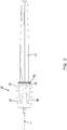
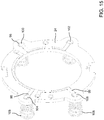
- a cordless lighting device is installed onto and over a portion of a distal end of the tool 12 and is removably thereto.
- a shaft 14 of the tool 12 can subsequently extend through an opening extending from a proximal end to a distal end of the lighting device 10 so that the device 10 surrounds the tool 12.
- the tool 12 is a BOVIE® pen, and the shaft 14 the blade of the BOVIE® pen.
- the present invention may be installed upon various different types of tools, both surgical and non-surgical, of various shapes and dimensions. As should be understood by those of ordinary skill in the art in accord with the detailed description herein, the dimension and shape of the light device 10 and its various features can be altered to accommodate and install on the desired tool.
- the lighting device 10 In general, once the lighting device 10 is frictionally engaged to a predetermined position on a tool 12, a directed stream of light automatically projects from the device 10.
- the lighting device 10 can be turned off and disengaged from the tool 12 by applying an axial force at the proximal end of the light attachment 10, which in turn disengages the lighting device 10 from the tool 12.
- the lighting device can alternatively include an on/off switch or button to control the operability of the light source.
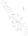
- FIGS. 3-7 illustrate various views and features of the lighting device 10.
- the lighting device 10 generally includes a housing 16, at least one light source 18, a first plate 20, a frame 22, a second plate 24, a sleeve 26 and a power source 28.
- the housing 16 includes a first housing element 30 and a second housing element 32 that is receivable within the first housing element 30 or otherwise connectable with the first housing element 30 to form the housing 16.
- the first housing element 30 and a second housing element 32 form a substantially fluid tight seal when connected so as to protect the internal components from fluid incursion into the housing 16.
- the housing 18 includes two housing elements 30, 32 in the embodiment shown, the housing 18 can readily be made of a single unitary element in place of the two independent elements.
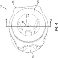
- the first housing element 30 includes an opening 34 extending from a proximal end to a distal end so as to define an internal cavity, a plurality of projections 36 that project outwardly about an outer periphery of the first housing element 30, and a recess 38 extending inwardly at a distal end of the housing 16 toward the proximal end.
- the light source 18 is located in the recess 38.
- the recess 38 protects the light source 18 from contact with external surfaces.
- the recess 38 helps limit or prevent the light source 18 from contacting external surfaces, such as tissue, that might be damaged by direct contact with the light source 18.
- the recess 38 also aids in directing the light source 18 toward a particular space being illuminated.
- surfaces of the recess 38 can be made of or coated with a reflective material, and in combination with the shape of the recess, as those of ordinary skill in the art should appreciate, redirect light emanating from the light source 18 to further direct or control the illumination.
- the light source 18 includes a plurality of LED lights arranged about the periphery of the distal end of the first housing element 30.
- the LED lights can produce white light or UV light to illuminate, for example, UV-luminescing dyes or materials.
- FIG. 3 , 5 , 9 , 10 , 13 and 16 two LED lights are used. The two LED lights ensure that the lighting device 10 is capable of directing enough light toward a particular space to illuminate the area with a reasonable power consumption, while maintaining a streamline profile of the device 10 to ensure a user's view is not blocked, limiting weight and cost of the lighting device.
- any number of lights can be used depending on the need of the user, and any light source that is known or may become known can be used in place of the LED lights, such as photoluminescence, chemoluminescence, electroluminescence, snap sticks, and glow stick.
- the lights 18 are substantially evenly angularly spaced in the device 10. This helps to more evenly distribute light.
- the invention contemplates any suitable arrangement of lights 18.
- the device 10 can be removably attachable to a tool 12 or object using various attachment mechanisms.
- the lighting device 10 can include a plurality of protrusions 40 that are arranged in recesses 42 formed in the housing 16 to removably attaching the lighting device 10 to a tool 14.
- the protrusions 40 are fixed within the recesses 42 by angled stops 43 that provide a frictional contact with the protrusions 40 by extending inwardly at an angle within the recesses 42 from the inner periphery of the housing 16.
- the protrusions 40 are also fixed within the recesses 42 by projections 44 that extend from the second housing element 32 and are contactable with the protrusions 40.
- the protrusions 40 are oriented at a forward angle toward the distal end of the device 10. They can be spring-loaded.
- the protrusions 40 include a first limb 46, a second limb 48 extending from the first limb 46 at a forward angle, and a tang 50 extending from the second limb 48 at a lesser forward angle.
- the protrusion 40 and the tang 50 is arranged and configured to contact the outer surface of the tool 12 when the device 10 is installed onto the tool 12.
- the contact between the tangs 50 and the tool 12 maintains the device 10 positioned on the tool 12.
- Contact between a tang 50 and the outer surface of the tool 12 creates friction that helps prevent relative sliding movement between the device 10 and tool 12.
- the amount of friction depends in part on the force the tang 50 asserts against the tool 12.
- the force depends upon the degree of interference between the tool 12 and tang 50, and the spring characteristics of the protrusions 40. As to the former, the greater the interference, that is, the degree the outer surface of the tool 12 is larger than the space between the tangs 50 in their non-compressed state, the more the tool surface will compress the protrusions 40, e.g., outwardly in the embodiment seen in FIG. 8 , and the greater the opposing spring force on the tool 12.
- the spring characteristics of the protrusion 40 depend upon the spring characteristics of the material out of which the protrusion 40 is made, and the configuration of the protrusion 40 itself.
- the second limb 48 acts as a lever arm with respect to the first limb 46.
- the effective spring rate of the protrusion decreases with increasing length and forward angle of the second limb 48.
- the amount of friction can be controlled, in part, by configuring the protrusion 40 and selecting the material of which the protrusion 40 is made. Accordingly, the frictional retaining force on the device 10 can be made sufficient to prevent the device 10 from unintended removal from the tool 12 under the expected operating conditions.
- the protrusion 40 can thus be manufactured out of metal, plastic, carbon fiber, or any other suitable material that is known or will become known.
- the frictional force is also dependent, in part, upon the frictional coefficient of the material of the tang 50 that contacts the tool 12.
- the tang could be made of a relative high friction material, such as rubber or other elastomeric material, or include a sleeve, end cap, or coating on or over the contact surface of the tang to provide the desired friction and gripping force.
- the protrusion 40 is made from metal or plastic, this may impart strength and overall desired spring rates for the protrusion 40, but provides a low friction contact surface with the tool.
- the tang 50 may be coated or otherwise include a material, e.g., rubber, having a higher friction coefficient to provide the desired frictional characteristics.
- the tang 50 may to a certain degree deform the outer surface of the tool 12, e.g., "dig into” it, so as to further secure the device 10 in addition to a merely frictional engagement.
- the inventor has found that even a small amount of deformation, in many cases not enough to adversely damage the tool 12, significantly increases the retention of the device 10.
- the forward angle of the second limb 48 provides self-locking or wedging effect against disengagement of the device 10 from the tool 12, while not overly inhibiting installation.
- the device 10 when the device 10 is inserted onto the tool 12 (or, conversely, the tool 12 is inserted through the cavity/opening in the device 10), when the outer surface of the tool 12 contacts the tangs 50, it imparts a force on the tangs 50, and thus the protrusions 40, in a distal direction. This biases the protrusions 40 forwardly (distally) and outwardly, such that the retaining force on the tool 12 is moderated.
- the opposite direction in FIG.
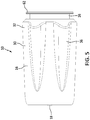
- the sleeve 26 is received within the frame 22 and the frame 22 is received within the housing 16.
- the sleeve 26 includes a flange 62 extending outwardly at a proximal end and a chamfered distal end surface 64.
- the chamfered surface 64 abuts or is near the second limb 48 of the protrusion.
- the chamfered surfaces 64 contact the second limb 48, and act as a wedge or ramp against the second limb 48.
- the sleeve 26 and flange 62 extend outwardly past (proximally) the housing 16, and forms the proximal end of the device 10.
- the user engages the rear (proximal) end of the device, e.g., the flange, and moves the device 10 distally (forwardly).
- the shaft 14 is removed from the tool 12 so as to allow the device 10 to be removed.
- the sleeve 26 is tapered having a substantially conical or tapered shape to extend over the distal end of a tool 14 having a substantially conical or tapered shape.
- the sleeve 26 can take the form of any known shape to accommodate a shape of the tool 14 on which the sleeve 26 is to be arranged.
- the sleeve 26 can be cylindrical to substantially match the contour of the tool 12 and/or shaft 14.
- the protrusions 40 can take on a number of structural configurations while still ensuring a sufficient gripping force such that the attachment 10 will not become detected without manual force applied to the sleeve 26.
- the protrusions 40 are not spring-loaded but relatively rigid and plastically deformable, In such embodiments, the protrusions 40 may be plastically deformed when the device 10 is installed on the tool 12 and/or when the device 10 is removed from the tool 12.
- the protrusions 40 are breakable or separable from the housing 16 upon exertion of a certain level of disengagement force on the device 10 (and thus the protrusions 40). Once broken or separated, the protrusions 40 do not hold the device 10 on the tool 12.
- the protrusions 40 may be provided with a selected level of disengagement force, e.g., the force at which the protrusions 40 will sufficiently deform, break or separate to allow the device 10 to disengage from the tool 12.
- the protrusions 40 may include a weakened portion or area at which the protrusion 40 is designed to deform, break or separate at a determinable and/or selectable force.
- attachment mechanisms and/or biasing members may be used in place of the protrusions 40.
- examples include, but are not limited to, adhesives, latches, snaps or cinch ties or fasteners, crank fasteners, rings, eyelets or any other technology that is known or may become known.
- the device 10 can in addition or alternatively include components that are magnetic. In this manner, the device 10 can be secured to the tool 12, at least in part, magnetically.
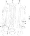
- FIG. 10 is an exploded view of an embodiment of the lighting device 10 illustrating the components that comprise the lighting device 10 and their arrangement within the housing 16.
- the power source 28 can include a battery or batteries.
- the batteries 28 shown in FIGS. 10 and 16 are pin-type batteries, which allow for generally longitudinal orientation (proximal-distal) and a minimized radial profile (diameter) of the lighting device 10.
- any other type of power source including solar power or capacitors, that is known or may become known can be used in place of batteries.
- other types of batteries can be used in place of the pin-type batteries, such as, for example, strip-style batteries, coin batteries and cloth batteries.
- the batteries can be for a single use or rechargeable.
- Single use or disposable batteries can include alkaline, carbon-zinc, lithium, silver-zinc, and zinc air.
- the pin-type battery 28 shown in FIGS. 10 and 16 is a single-use lithium battery.
- a pin-type battery produces a high density of energy (e.g., 800 Wh/l), can be used under a wide range of temperatures (e.g., -20 °C to approximately about 60 °C), can store energy for over two years, has a low discharge rate (e.g., less than 1%/year), is leak resistant, reliable, and is an eco-friendly product that is free of heavy metals.
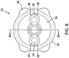
- FIG. 11 shows a cross-sectional view of an embodiment of the first housing element 30 taken along line C-C from FIG. 10 .
- the first housing element 30 can include projections 36 that project outwardly therefrom to accommodate the profile of the batteries 28, recesses 42 formed within the first housing element 30 to receive the projections 40, and openings 34, 58, 60 formed in a wall 56 near the distal end of the housing 16.
- the first housing element 30 can further include a plurality of projections 66 extending inwardly to aid in connecting the housing 16 to the frame 22 and O-rings 68 or other elastomeric means can be arranged within the openings of the housing to protect against ingress of contaminants or fluids.
- the first plate 20 is arranged within the housing 16 between a wall 56 near the distal end of the housing 16 and the frame 22, and the light sources 18 project outwardly through openings 58, 60 in the wall 56 of the housing 16.
- the second plate 24 is arranged within the housing 16 near a proximal end of the housing 16.
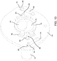
- Fig. 13 shows an embodiment of the first plate 20 having an opening 76 therein for receiving therethrough a shaft 14 of a tool 12 and light sources 18 extending through a plurality of openings 78, 80, 82, 84 extending through the plate 20 about the periphery of the plate 20.
- the light source 18 include prongs 86, 88 that extend through openings 78, 80, 82, 84 in the first plate 20 and are contactable with the plurality of electric circuits 90, 92, 94 that are affixed to the first plate 20 or formed therein.
- FIGS. 14 and 15 show, respectively, front and rear perspective views of the second plate 24.
- the second plate 24 includes a plurality of electric circuits 96, 98, 99 that are affixed to the first plate 24 or formed therein, a plurality of openings 100, 102, 104, 106 extending through the circuits 96, 98 and second plate 24, a plurality of compression springs 108 affixed to the circuits 96, 98, 99 on a first side of the second plate 24 at the openings 100, 102, 104, 106 extending through the plate 24.
- compression springs 108 are shown in the embodiment, other biasing mechanisms that are known or may become known can alternatively be used.
- a plurality of power sources 28 extend between the first plate 20 and the second plate 26 and the terminals 110 of the power source 28 extend through the openings 100, 102, 104, 106 in the second plate 26.
- the terminals 110 can be soldered to the second side of the second plate 26 to fix the power sources 28 in place.
- the compression springs 108 form a contact with the conductive outer shell of the power source 28, which can be, for example aluminum or steel, in a compressed state.
- the restorative spring force in the compressing springs 108 help maintain contact with the shell of the power source 28.
- the radially-inward terminals 86, 88 of the light sources 18 are not in electrical communication with each other. Thus, no complete or closed circuit is formed, and no power flows to the light sources 18.
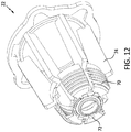
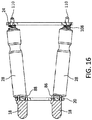
- FIG. 12 is a perspective view of an embodiment of the frame 22.
- the frame 22 includes a plurality of bellows 70 that extend from a distal end of the frame 22, and a conductive ring or plate 72 made of any suitable conductive material, e.g., conductive metal, is affixed to the distal end of the frame 22 or molded therein.
- At least the bellows 70 of the frame 22 are made from an elastomeric material allowing the frame 22 and/or bellows 70 to expand (lengthen) and contract (shorten).
- the frame 22 is made at least in part from an elastomeric material, the frame 22 can be made from any other material that allows at least the bellows 70 to expand and contract.
- the frame 22 can thus be made from a combination of materials or a single elastomeric material.
- Gaps extend about the circumference of the distal end of the frame 22, between the bellows 70 for clearance purposes and interaction with other elements of the device 10.
- the frame 22 also includes a plurality of projections 74 that extend radially inwardly and outwardly to connect the frame 22 to the housing 16 and the sleeve 26 to connect the frame 22 to other elements of the light attachment 10.
- the frame 22 and the sleeve 26 are shown in FIG. 10 as two independent elements, the frame 22 and the sleeve 26 can be formed as a single unitary element.
- the bellows 70 are in a natural condition sufficiently compressed so that conductive ring 72 is not in contact with, e.g., gapped from, the first plate 20. Because the radially-inward terminals 86, 88 of the light sources 18 are not in electrical communication with each other, the electrical circuit (as seen in FIG. 16 ) is open and the light sources are not illuminated.
- the bellows 70 have a bellows ring 70a (as seen, e.g., in FIG. 10 ) defining an opening through which the tool 12 extends upon installation of the device 10 on the tool 12.
- the bellows 70 are expanded axially. Once the device 10 is placed over a selected portion of the distal end of the tool 12, it engages the tool 12. During engagement, friction between the tool 12 and the frame 22, e.g., the bellows ring 70a causes the distal end of the frame 22, e.g., the bellows 70, to expand, i.e., lengthen, relative to the other components of the device 10.
- the conductive ring 72 moves distally relative to the first plate 20 until it contacts the first plate 20. More specifically, the conductive ring contacts the radially-inward prongs 86, 88 of the light sources 18, placing them in electrical communication with each other. This completes and closes the electrical circuit with the power source 28, electricity is delivered the light sources 18, and the light sources 18 illuminate.
- a reverse action turns the light source 18 off.
- the frictional forces on the frame 22 and bellows 70 is in the opposite direction than during installation. These forces, and also the restorative spring force stored in the bellows 70 due to their extension during installation, cause the frame 22, e.g., the bellows 70, to contract, which moves the conductive plate 72 in a direction proximally relative to other components of the device 10.
- the conductive plate 72 thus separates from the first plate 20, and the radially-inward prongs 86, 88, as the bellows 70 contract or compress toward the position shown in FIG. 9 .
- the prong 86, 88 are removed from electrical communication with each other, which opens the circuit.
- the light source 18 is no longer illuminated when the lighting device 10 is not attached to the tool 14.
- the lighting device 10 can include a switch or button that the user manually operates to turn the device 10 on and off.
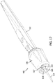
- FIG. 17 shows an alternative cordless lighted device 100 that is retained on the tool 112 by the tool itself.
- the tool 112 has a proximal end and a distal end.
- the tool 112 has an opening at the distal end to receive the shaft 114, e.g., a blade.
- the shaft 114 is insertable into and retained by the body of the tool 112 in a known manner.
- the shaft 114 has collar, rim or shoulder 115 configured to seat against the distal end of the tool 112 when inserted.
- the device 100 similar to the lighted device 10, has a housing 116, and at least one light source 118 powered by a cordless power source, and receives the tool through an opening or cavity extending from the proximal end to the distal end of the device 100.
- the cavity is shaped and configured so that the device 110 encompasses, e.g., is attachable to, a predetermined portion of the tool 112.
- the device 110 is configured to engage upon the distal end of the tool 112.
- the light source 118 is located as close to the shaft 114 as possible, e.g., close to the operating site, without interfering with the functioning of the tool 112.
- the housing 116 includes a protrusion 117 extending from the distal end and around the through opening in the device.
- the protrusion 117 forms a rim 119 at its distal end.
- the inner diameter of the protrusion 117 and the rim 119 is large enough to permit the shaft 114 to be inserted into and mounted to the distal end of the tool, but smaller than the outer diameter of the collar 115 of the shaft. Accordingly, after the shaft 114 is inserted into the tool, the dimensional interference between the collar 115 and the rim 119 prevents the device 100 from being removed off from the distal end of the tool 112.
- the shaft 114, and more specifically the shoulder 115 secures the device 110 to the tool. Where the shaft 144 can be removed from the tool 112, the device 110 can then be removed from the tool in a similar manner as described above with respect to the lighting device 10.
- FIG. 18 shows an alternate manner of retaining a lighting device 300 on a tool.
- the features of the lighting device 300 are substantially the same as those shown in the embodiments of the lighting devices 10 and 100 except where indicated.
- the device 300 includes a housing 301 that includes split collar 302 with a slit 303 extending longitudinally partway through extending from the proximal end of the device 300 part way toward the distal end of the device 300.
- the housing 301 is made of an at least slightly flexible or spring-like material.
- the cavity or opening of the device 300 is smaller than the outer surface of the tool. When the device 300 is installed on the tool, the dimensional interference between the tool and the cavity of the device 300 causes the slit to spread or expand due to the flexibility of the material of the housing 301. Thus, the cavity or opening will expand to accommodate the outer surface of the tool.
- the restorative spring-like force stored in the deflected material of the housing 301 will impose an opposing compressive force against the outer surface of the tool, providing a gripping and/or frictional force on the tool. This force will help maintain the device 300 attached to the tool.
- the retention force can be selected as desired or suitable.
- the force can be selected by selecting, among other things as will be understood by those of ordinary skill in the art, the material of the housing in order to have a selected material flexibility, the amount of dimensional interference between the tool and the cavity of the device 300, which determines the amount of flexing or deflection necessary to install the device 300 on the tool, and the shape, size and configuration of the slot 301, which effects the overall flexibility of the housing 301.
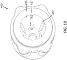
- FIG. 19 depicts a further alternative configuration for securing a lighting device 400 to a tool.
- the features of the lighting device 400 are substantially the same as those shown in the embodiments of the lighting devices 10, 100 and 300 except where indicated.
- the sleeve 426 includes a plurality of projections 427 extending from the inner peripheral surface of the sleeve 426 radially inwardly into the cavity of the device into which the tool is received.
- the projections 427 are flexible, compressible and/or elastomeric. The distance the projections 427 extend into the cavity is selected to provide a dimensional interference between the projections 427 and the outer surface of the tool.
- the projections When the tool is inserted into the cavity, the projections are flexed or compressed to accommodate the tool. In turn, the restorative spring force in the compressed/flexed projections 427 asserts an opposing inwardly directed compressive force against the outer surface of the tool. This generates a gripping/frictional force between the projections 427 and the tool that helps maintain the device 400 engaged on the tool.
- the retention force can be selected as desired or suitable.
- the force can be selected by selecting, among other things as will be understood by those of ordinary skill in the art, the material of the projections 427 in order to have a selected material compressibility/flexibility and also frictional coefficient between the projections 427 and tool, and the amount of dimensional interference between the tool and the projections 427, which determines the amount of flexing or deflection necessary to install the device 400 on the tool, and thus the opposing compressive force.
- the retention force can be selected so as that the lighting device 400 will not become unintentionally disengaged from the tool during operation, but provides a reasonable level of force for the user to install and disengage the lighting device 400.
- the projections 427 contain magnetic material.
- the device 400 may be secured to a magnetic tool 12, at least in part, magnetically.
- the degree of magnetic force between the projections 427 and the tool 12 may be selected to be great enough so as to substantially prevent unintentional disengagement between the device 400 and the tool 12, but at a level that permits intentional disengagement when desired.
- the lighting devices of the invention provide multiple advantages.
- One advantage of the light attachment is its size.
- the light attachment has a diameter that extends only somewhat beyond the outer periphery of the tool to allow a user to easily manipulate the tool while not hindering maneuverability or blocking the user's line of vision.
- the packaging advantage is due, in certain embodiments, to the use of pin-shaped batteries oriented in a generally proximal-distal alignment with the device.
- the light attachment is easily attachable to a tool and detachable from the tool.
- the light attachment can easily slide over a distal end of a tool for engagement with the tool during use.
- the user merely has to apply axial pressure to the proximal end of the light attachment to disengage the light attachment.
- unintentional dislodging of the device from the tool is mitigated.
- the light attachment simultaneously attaches to a tool and illuminates a light source ensuring efficient assembly and use.
- the light attachment includes attachment means that are engageable and disengageable with a tool; there are no additional fasteners required to ensure the device will not automatically become disengaged from the tool during use.
- the devices are cordless with a self-contained power source.
- the device does not require attachment via an electrical cord to a remote electrical outlet or light source.
- a cord adds unwieldiness to the tool, and may require assistance to manipulate.
- Known corded devices may also become hot and burn the user and/or the patient, and possibly even cause a fire.
- the present invention decreases the risk of burning or causing a fire.
- a further advantage is that the light attachment of the invention is securable to the tool at a desired or selected location. This permits optimal placement of the device, both from an illumination perspective and an operational perspective of the tool.
Priority Applications (1)
| Application Number | Priority Date | Filing Date | Title |
|---|---|---|---|
| EP21177169.6A EP3906885A3 (en) | 2013-04-01 | 2014-04-01 | Lighting device |
Applications Claiming Priority (2)
| Application Number | Priority Date | Filing Date | Title |
|---|---|---|---|
| US201361853232P | 2013-04-01 | 2013-04-01 | |
| PCT/US2014/032595 WO2014165551A1 (en) | 2013-04-01 | 2014-04-01 | Lighting device |
Related Child Applications (1)
| Application Number | Title | Priority Date | Filing Date |
|---|---|---|---|
| EP21177169.6A Division EP3906885A3 (en) | 2013-04-01 | 2014-04-01 | Lighting device |
Publications (3)
| Publication Number | Publication Date |
|---|---|
| EP2981394A1 EP2981394A1 (en) | 2016-02-10 |
| EP2981394A4 EP2981394A4 (en) | 2017-04-19 |
| EP2981394B1 true EP2981394B1 (en) | 2021-06-02 |
Family
ID=51620673
Family Applications (2)
| Application Number | Title | Priority Date | Filing Date |
|---|---|---|---|
| EP21177169.6A Pending EP3906885A3 (en) | 2013-04-01 | 2014-04-01 | Lighting device |
| EP14778738.6A Active EP2981394B1 (en) | 2013-04-01 | 2014-04-01 | Lighting device |
Family Applications Before (1)
| Application Number | Title | Priority Date | Filing Date |
|---|---|---|---|
| EP21177169.6A Pending EP3906885A3 (en) | 2013-04-01 | 2014-04-01 | Lighting device |
Country Status (8)
| Country | Link |
|---|---|
| US (4) | US9851060B2 (ja) |
| EP (2) | EP3906885A3 (ja) |
| JP (2) | JP6379178B2 (ja) |
| CN (2) | CN105163912B (ja) |
| CA (2) | CA2910032C (ja) |
| HK (1) | HK1218900A1 (ja) |
| RU (1) | RU2705046C2 (ja) |
| WO (1) | WO2014165551A1 (ja) |
Families Citing this family (34)
| Publication number | Priority date | Publication date | Assignee | Title |
|---|---|---|---|---|
| US10136960B2 (en) | 2011-02-28 | 2018-11-27 | Richard P. Fleenor | Hand-held electrosurgical instrument |
| USD759868S1 (en) | 2012-10-17 | 2016-06-21 | Welch Allyn, Inc. | Illuminator for a medical device or the like |
| USD741531S1 (en) | 2012-10-17 | 2015-10-20 | Welch Allyn, Inc. | Illuminator for a medical device or the like |
| US9314149B2 (en) | 2013-03-15 | 2016-04-19 | Welch Allyn, Inc. | Illumination device, system, and method of use |
| CA2910032C (en) * | 2013-04-01 | 2022-10-04 | Vinod V. Pathy | Lighting device |
| USD938095S1 (en) * | 2013-04-01 | 2021-12-07 | Pathy Medical, Llc | Lighting device |
| USD753295S1 (en) * | 2014-06-27 | 2016-04-05 | Welch Allyn, Inc. | Illuminator for a medical device or the like |
| CA2956796A1 (en) | 2014-08-12 | 2016-02-18 | Invuity, Inc. | Illuminated electrosurgical system and method of use |
| CN115568937A (zh) | 2014-12-08 | 2023-01-06 | 英弗伊蒂股份有限公司 | 用于电外科照明和感测的方法和装置 |
| USD781477S1 (en) * | 2015-04-06 | 2017-03-14 | Clearspec, Llc | Illuminator for a medical speculum |
| US9964264B2 (en) | 2015-05-18 | 2018-05-08 | Tti (Macao Commercial Offshore) Limited | Flashlight |
| USD761962S1 (en) | 2015-06-03 | 2016-07-19 | Richard P. Fleenor | Light tunnel for electrosurgical pencil |
| WO2016196562A1 (en) * | 2015-06-03 | 2016-12-08 | Fleenor Richard P | Multi-feature electrosurgical instrument |
| US20180029207A1 (en) * | 2016-07-29 | 2018-02-01 | Carolyn Hieronymus | Orthotic Removal Tool |
| US10390903B2 (en) | 2016-10-24 | 2019-08-27 | Steven Warnock | Illuminated apparatus with telescoping for electrocautery devices and method of use |
| US10801702B1 (en) | 2016-12-16 | 2020-10-13 | Rick D. Thurman | Light fixture comprising carbon materials and methods therefor |
| US10408431B1 (en) * | 2016-12-16 | 2019-09-10 | Rick D. Thurman | Light fixture comprising carbon fiber materials |
| CN206663154U (zh) * | 2017-02-21 | 2017-11-24 | 上海拓岚机械科技有限公司 | 一种多功能套筒扳手 |
| US10401001B2 (en) * | 2017-05-10 | 2019-09-03 | Sunoptic Technologies Llc | Disposable light source for an endoscope or retractor |
| US10194975B1 (en) | 2017-07-11 | 2019-02-05 | Medtronic Advanced Energy, Llc | Illuminated and isolated electrosurgical apparatus |
| US10532449B2 (en) * | 2017-07-26 | 2020-01-14 | Carolyn Hieronymus | Orthotic removal tool |
| US20200330129A9 (en) | 2017-09-09 | 2020-10-22 | June Medical Ip, Llc | Passive safety intraosseous device |
| US11357515B2 (en) | 2017-09-09 | 2022-06-14 | June Access Ip, Llc | Intraosseous device having retractable motor/stylet assembly and automatic stylet point cover upon retraction operation |
| JP7344211B2 (ja) * | 2018-02-05 | 2023-09-13 | アルコン インコーポレイティド | 照明付きカニューレ |
| US10226611B1 (en) * | 2018-05-11 | 2019-03-12 | Ushio America, Inc. | Grip light |
| EP3810025B1 (en) * | 2018-06-19 | 2022-06-15 | Medtronic Advanced Energy LLC | Illuminated electrosurgical devices, systems and methods |
| US11253335B2 (en) * | 2018-10-17 | 2022-02-22 | Pathy Medical, Llc | Lighting devices for attachment to a handheld electrosurgical instrument |
| JP2022527729A (ja) | 2018-10-17 | 2022-06-06 | パシー メディカル, エルエルシー | 照明装置をハンドヘルド電気外科用器具に取り付けるためのアダプタアセンブリ |
| AU2020244736A1 (en) | 2019-03-27 | 2021-08-26 | Pathy Medical, Llc | Lighting devices for handheld surgical instruments, holsters for surgical instruments with lighting devices and kits containing surgical instruments and lighting devices |
| US10716642B1 (en) | 2019-07-23 | 2020-07-21 | Pathy Medical, Llc | Lighting device for handheld surgical instrument with smoke evacuation system |
| US20210212748A1 (en) * | 2020-01-10 | 2021-07-15 | Pathy Medical, Llc | Lighted electrocautery blade assembly for handheld electrosurgical instrument |
| US11391456B2 (en) | 2020-09-11 | 2022-07-19 | Nova Wildcat Shur-Line, Llc | Handle adapter assembly including a light assembly |
| US11484952B2 (en) * | 2020-10-28 | 2022-11-01 | Marc Reid | Illuminated tool bit assembly |
| DE102021106818B3 (de) * | 2021-03-19 | 2022-06-30 | Thomas Engelhardt | Vorrichtung zur Ausleuchtung von Arbeitsbereichen, Verfahren zu deren Benutzung und Verwendung |
Citations (1)
| Publication number | Priority date | Publication date | Assignee | Title |
|---|---|---|---|---|
| CN200982612Y (zh) * | 2006-12-08 | 2007-11-28 | 赵美莲 | 附挂型工具灯 |
Family Cites Families (177)
| Publication number | Priority date | Publication date | Assignee | Title |
|---|---|---|---|---|
| CA79913A (en) | 1903-02-23 | 1903-03-31 | Frank John Lowery | Sash balance and fastener |
| CA102076A (en) | 1906-10-26 | 1906-11-20 | John B. Alderich | Railway switch |
| US2242536A (en) * | 1940-03-01 | 1941-05-20 | Glen E Montgomery | Work illuminating tool |
| US4542741A (en) | 1981-07-17 | 1985-09-24 | Burgin Kermit H | Surgical instrument with incorporated lighting system |
| US4539003A (en) * | 1983-01-24 | 1985-09-03 | Tucker Annabelle D | Angio-catheter/infusion tubing lock |
| US4657012A (en) | 1983-11-16 | 1987-04-14 | Burgin Kermit H | Surgical instrument with incorporated lighting system |
| CA1216202A (en) | 1984-08-22 | 1987-01-06 | David J. Walsh | Light attachment for speculum |
| US5281134A (en) | 1991-11-19 | 1994-01-25 | Schultz Allen J | Fiber optic illumination system for dental instruments |
| US5693044A (en) | 1992-12-11 | 1997-12-02 | Cosmescu; Ioan | Telescopic surgical device and method therefor |
| JPH07275261A (ja) * | 1994-04-11 | 1995-10-24 | Morita Mfg Co Ltd | 照明装置内蔵型歯科用ハンドピース |
| US5716320A (en) | 1994-10-31 | 1998-02-10 | Buttermore; William J. | Illuminated intraocular surgical instrument |
| US5683246A (en) | 1995-04-17 | 1997-11-04 | Micro Motors, Inc. | Illumination apparatus for dental handpiece |
| US6185356B1 (en) | 1995-06-27 | 2001-02-06 | Lumitex, Inc. | Protective cover for a lighting device |
| US5692863A (en) | 1996-01-25 | 1997-12-02 | Fairchild Fasteners-U.S. | Self-locking preload controlling nut |
| US5908433A (en) | 1996-05-10 | 1999-06-01 | Stryker Corporation | Carpal tunnel knife |
| US6129662A (en) | 1996-06-03 | 2000-10-10 | Cogent Light Technologies, Inc. | Surgical tool with surgical field illuminator |
| US5954713A (en) | 1996-07-12 | 1999-09-21 | Newman; Fredric A. | Endarterectomy surgical instruments and procedure |
| US7112199B2 (en) | 1996-09-20 | 2006-09-26 | Ioan Cosmescu | Multifunctional telescopic monopolar/bipolar surgical device and method therefore |
| US5845986A (en) * | 1996-09-24 | 1998-12-08 | Breen; William Charles | Light for manual rotary tool |
| US7083613B2 (en) | 1997-03-05 | 2006-08-01 | The Trustees Of Columbia University In The City Of New York | Ringed forceps |
| DE29706249U1 (de) * | 1997-04-08 | 1997-05-22 | Tseng Kuo Hwa | Beleuchtungseinrichtung an einem Werkzeug |
| US6196968B1 (en) | 1997-06-02 | 2001-03-06 | General Surgical Innovations, Inc. | Direct vision subcutaneous tissue retractor and method for use |
| US6080105A (en) | 1997-06-26 | 2000-06-27 | Spears; Robert A. | Illuminated dental and surgical retractor and kit including plurality of blades and blades recharging base |
| US6739744B2 (en) | 1997-07-02 | 2004-05-25 | Lumitex, Inc. | Light delivery systems and applications thereof |
| JPH1147276A (ja) * | 1997-08-07 | 1999-02-23 | Shinji Kondo | 注射針保護キャップ及びこれを用いた注射針処理具 |
| US5928140A (en) | 1997-09-02 | 1999-07-27 | Hardten; David R. | Illuminated iris retractor probe system |
| US6084422A (en) | 1997-11-10 | 2000-07-04 | Bartholomew; Mark | Printed circuit board testing device |
| IT1296089B1 (it) | 1997-11-10 | 1999-06-09 | Mectron Di Bianchetti Fernando | Manipolo odontoiatrico con sorgente luminosa a scopo diagnostico |
| US6277064B1 (en) | 1997-12-30 | 2001-08-21 | Inbae Yoon | Surgical instrument with rotatably mounted offset endoscope |
| US6164855A (en) * | 1998-03-26 | 2000-12-26 | Bic Corporation | Writing instrument with finger gripping device |
| US5967971A (en) | 1998-04-14 | 1999-10-19 | Bolser; Jeffrey William | Surgical instrument |
| US6228025B1 (en) | 1998-05-01 | 2001-05-08 | Genzyme Corporation | Illuminated saphenous vein retractor |
| DE29904917U1 (de) * | 1999-03-18 | 2000-03-23 | Bundesdruckerei Gmbh | UV-LED Pointer in einem Handwerkzeug |
| US6270491B1 (en) | 1999-04-06 | 2001-08-07 | Duke University | Intensity controllable hand-held surgical light |
| JP2000316874A (ja) * | 1999-05-07 | 2000-11-21 | Morita Mfg Co Ltd | 照明機構付き歯科用器具 |
| WO2001006176A1 (en) * | 1999-07-20 | 2001-01-25 | Karram Mickey M | Surgical illumination device and method of use |
| US6325522B1 (en) | 1999-09-20 | 2001-12-04 | Harald Walian | Hand held device providing effective site illumination |
| US6585727B1 (en) | 1999-10-22 | 2003-07-01 | Genzyme Corporation | Surgical instrument light source and surgical illumination method |
| US6223633B1 (en) * | 1999-10-29 | 2001-05-01 | Chen Chien-Chich | Screwdriver with control portion for selectively retaining tips therein |
| US6213621B1 (en) * | 1999-12-14 | 2001-04-10 | Kuo Cheng Chien | Tool kit with illumination function |
| US6322499B1 (en) | 2000-01-20 | 2001-11-27 | Genzyme Corporation | Pivotal and illuminated saphenous vein retractor |
| US6497654B1 (en) | 2000-02-18 | 2002-12-24 | Genzyme Corporation | Illuminated rectal retractor |
| IL135371A (en) | 2000-03-30 | 2006-10-31 | Roie Medical Technologies Ltd | Resectoscope |
| CN2424886Y (zh) * | 2000-05-08 | 2001-03-28 | 洪坤池 | 改良的多用途工具 |
| US6496718B1 (en) | 2000-05-12 | 2002-12-17 | The Trylon Corporation | Body cavity light using diffuse light source |
| US6648902B2 (en) | 2000-07-20 | 2003-11-18 | Gmp Surgical Solutions, Inc. | Fiberoptic lighting accessory |
| US6554768B1 (en) | 2000-09-05 | 2003-04-29 | Genzyme Corporation | Illuminated deep pelvic retractor |
| US6394950B1 (en) | 2000-10-17 | 2002-05-28 | Sol Weiss | Surgical instrument |
| US6517551B1 (en) | 2000-11-22 | 2003-02-11 | George Mark Driskill | Intravascular foreign object retrieval catheter |
| US6602188B2 (en) | 2001-02-22 | 2003-08-05 | Jeffrey William Bolser | Surgical instrument and associated method |
| US6562032B1 (en) | 2001-03-26 | 2003-05-13 | Ellman Alan G | Electrosurgical instrument with vibration |
| US6769911B2 (en) | 2001-04-16 | 2004-08-03 | Advanced Research & Technology Institue | Luminescence assisted caries excavation |
| US7106523B2 (en) | 2002-01-11 | 2006-09-12 | Ultradent Products, Inc. | Optical lens used to focus led light |
| US6817978B2 (en) | 2002-01-23 | 2004-11-16 | Teleflex-Ct Devices Incorporated | Illuminated retractor for use in connection with harvesting a blood vessel from the arm |
| AU2003225691A1 (en) | 2002-03-06 | 2003-09-22 | James S. Simon | Chemiluminescently illuminated medical appliances |
| US6805666B2 (en) | 2002-05-23 | 2004-10-19 | Donna D. Holland | Pivotal and illuminated saphenous vein retractor with tapered design |
| US6786628B2 (en) | 2002-07-03 | 2004-09-07 | Advanced Medical Optics | Light source for ophthalmic use |
| US7322135B2 (en) | 2002-12-02 | 2008-01-29 | Geeta Wagle Gulati | Device for medical instrument |
| US7390298B2 (en) | 2003-01-06 | 2008-06-24 | City Of Hope | Expandable surgical retractor for internal body spaces approached with minimally invasive incisions or through existing orifices |
| US7503894B2 (en) | 2003-01-31 | 2009-03-17 | Zimmer Technology, Inc. | Lit retractor |
| AT411867B (de) | 2003-02-20 | 2004-07-26 | W & H Dentalwerk Buermoos Gmbh | Adapter für ein medizinisches lichtgerät |
| US20040166475A1 (en) | 2003-02-24 | 2004-08-26 | George Nikolov | Sterilizable dental and surgical instrument |
| US7008076B2 (en) * | 2003-03-03 | 2006-03-07 | Zirk Jason E | Folding knife light tool |
| US20070066872A1 (en) | 2003-03-07 | 2007-03-22 | Paul Morrison | IIIuminable retractor |
| US6988814B1 (en) * | 2003-04-25 | 2006-01-24 | Carlos Correa | Illumination assembly usable with a plurality of devices |
| US7108395B2 (en) | 2003-04-25 | 2006-09-19 | Carlos Correa | Illumination assembly usable with a plurality of devices |
| US7141015B2 (en) | 2003-05-09 | 2006-11-28 | Bernard Joseph Ruane | Expandable and pivotally adjustable surgical retractor |
| US20040242970A1 (en) | 2003-05-28 | 2004-12-02 | Burns Lance S. | Methods and apparatus for retracting the soft tissues of the mouth |
| US7481766B2 (en) | 2003-08-14 | 2009-01-27 | Synthes (U.S.A.) | Multiple-blade retractor |
| US7393114B2 (en) | 2003-09-09 | 2008-07-01 | Devlin Joseph E | Lighted grip and alligator clip cord for tattoo machine |
| US7309341B2 (en) | 2003-09-30 | 2007-12-18 | Ethicon Endo-Surgery, Inc. | Single lumen anastomosis applier for self-deploying fastener |
| US6955444B2 (en) | 2003-11-12 | 2005-10-18 | Visiled, Inc. | Surgical headlight |
| JP4822673B2 (ja) * | 2004-04-30 | 2011-11-24 | 株式会社モリタ製作所 | 口腔内照明装置 |
| JP4822698B2 (ja) * | 2003-12-08 | 2011-11-24 | 株式会社モリタ製作所 | 歯科治療装置 |
| US8371848B2 (en) | 2003-12-08 | 2013-02-12 | J. Morita Manufacturing Corporation | Dental diagnostic and treatment apparatus |
| US7500947B2 (en) | 2004-01-29 | 2009-03-10 | Cannonflow, Inc. | Atraumatic arthroscopic instrument sheath |
| DE202004002963U1 (de) | 2004-02-26 | 2004-04-22 | Aesculap Ag & Co. Kg | Beleuchtungselement für ein Chirurgisches Instrument |
| EP1568938B1 (de) | 2004-02-28 | 2006-09-27 | TRUMPF Kreuzer Medizin Systeme GmbH + Co. KG | Operationsleuchte |
| US7963976B2 (en) | 2004-11-04 | 2011-06-21 | Dynamic Surgical Inventions, Llc | Articulated surgical probe and method for use |
| WO2006065271A2 (en) | 2004-12-15 | 2006-06-22 | Embo-Optics, Llc | Point of infusion lighting device |
| US7364379B2 (en) * | 2004-12-30 | 2008-04-29 | Cotapaxi Custom Design And Manufacturing, Llc | Implement grip |
| US8029439B2 (en) | 2005-01-28 | 2011-10-04 | Stryker Corporation | Disposable attachable light source unit for an endoscope |
| CA2597892C (en) | 2005-02-14 | 2013-04-16 | Vascular Technologies, Inc. | Probes for electrical current therapy of tissue, and methods of using same |
| US20060189849A1 (en) | 2005-02-22 | 2006-08-24 | Sharratt Todd W | Surgical illumination device and method of using |
| US9005115B2 (en) | 2005-04-04 | 2015-04-14 | Invuity, Inc. | Illuminated telescoping cannula |
| WO2006119270A1 (en) | 2005-05-04 | 2006-11-09 | Synergetics, Inc. | Illuminated laser probe with multiplied area of illumination |
| US8684577B2 (en) | 2005-05-13 | 2014-04-01 | Invuity, Inc. | Body cavity illumination system |
| US20060282072A1 (en) | 2005-06-11 | 2006-12-14 | Desrosier Paul | Electrocautery instrument |
| US20080147058A1 (en) | 2005-06-13 | 2008-06-19 | Horrell Robin S | Electrocautery system, provided with safe lighting during operational use |
| US7270439B2 (en) | 2005-06-13 | 2007-09-18 | Horrell Robin S | Compact lighting system attachable to a surgical tool and method of use thereof |
| IL169641A0 (en) | 2005-07-12 | 2009-02-11 | Sialo Lite Ltd | Device and system for root canal treatment |
| US7399101B2 (en) | 2005-07-20 | 2008-07-15 | Streamworks, Inc. | Lighted plier hand tool apparatus |
| WO2007021914A2 (en) | 2005-08-11 | 2007-02-22 | Synergetics, Inc. | Illuminated directional laser probe |
| US20070049927A1 (en) | 2005-08-31 | 2007-03-01 | Saltzman Darin J | Electrosurgical pencil with a light |
| US20070060795A1 (en) | 2005-09-14 | 2007-03-15 | Spotlight Surgical, Inc. | Lighted surgical retractors with LED illumination light engines |
| US7771350B2 (en) * | 2005-10-21 | 2010-08-10 | General Electric Company | Laryngoscope and laryngoscope handle apparatus including an LED and which may include an ergonomic handle |
| US8409088B2 (en) | 2006-01-18 | 2013-04-02 | Invuity, Inc. | Retractor illumination system |
| EP1983883B1 (en) | 2006-02-07 | 2015-11-18 | Boston Scientific Limited | Medical device light source |
| USD587832S1 (en) | 2006-03-09 | 2009-03-03 | Zumtobel Lighting Gmbh & Co. Kg | LED lighting fixture |
| US8047987B2 (en) | 2006-05-26 | 2011-11-01 | Invuity, Inc. | Blade insert illuminator |
| US7686492B2 (en) | 2006-06-13 | 2010-03-30 | Invuity, Inc. | Film illumination system |
| US8114121B2 (en) | 2006-06-22 | 2012-02-14 | Tyco Healthcare Group Lp | Tissue vitality comparator with light pipe with fiber optic imaging bundle |
| EP1882553B1 (en) * | 2006-07-26 | 2011-09-21 | Hitachi Koki Co., Ltd. | Power tool equipped with light |
| US20100190129A1 (en) | 2006-08-08 | 2010-07-29 | Mony Paz | Combination dental hand tool |
| US20080146935A1 (en) | 2006-10-13 | 2008-06-19 | Sen-Yung Liu | Auxiliary Positioning Device For Ultrasonic Apparatus |
| EP1932489B1 (de) | 2006-11-30 | 2019-07-03 | W & H Dentalwerk Bürmoos GmbH | Medizinisches Handstück mit Beleuchtungsvorrichtung |
| PT103654B (pt) | 2007-02-07 | 2009-04-30 | Fernando Antonio Cepeda Costa | Aparelho iluminador para instrumentos cirúrgicos |
| US20080266840A1 (en) | 2007-02-12 | 2008-10-30 | Engineered Medical Solutions Company, Llc | Surgical illumination device |
| WO2008106590A2 (en) | 2007-02-28 | 2008-09-04 | Doheny Eye Institute | Portable handheld illumination system |
| US20080266845A1 (en) * | 2007-04-25 | 2008-10-30 | Unity Opto Technology Co., Ltd. | Auxiliary lighting device |
| GB0708761D0 (en) | 2007-05-04 | 2007-06-13 | Evexar Medical Ltd | Improvements in and relating to medical instruments |
| DE102007022205A1 (de) | 2007-05-11 | 2008-11-13 | Kaltenbach & Voigt Gmbh | Handgerät zur Abgabe eines pastösen Füllungsmaterials |
| US8506565B2 (en) * | 2007-08-23 | 2013-08-13 | Covidien Lp | Electrosurgical device with LED adapter |
| GB0718268D0 (en) | 2007-09-19 | 2008-10-08 | Ayrshire And Arran Health Board | Retractor with integrated light source |
| US7931550B2 (en) * | 2007-10-10 | 2011-04-26 | Grace Engineering Corp. | Programmable lighted archery nock |
| US7631981B2 (en) | 2007-10-15 | 2009-12-15 | Utah Medical Products, Inc. | Disposable medical-examination light |
| US8088066B2 (en) | 2007-10-24 | 2012-01-03 | Invuity, Inc. | Blade insert illuminator |
| US7954687B2 (en) | 2007-11-06 | 2011-06-07 | Tyco Healthcare Group Lp | Coated surgical staples and an illuminated staple cartridge for a surgical stapling instrument |
| DE102007055003A1 (de) | 2007-11-14 | 2009-05-20 | Carl Zeiss Surgical Gmbh | Medizinische Beleuchtungseinheit |
| JP5483518B2 (ja) * | 2007-12-27 | 2014-05-07 | 株式会社モリタ製作所 | 診療表示装置、診療装置及び診療用表示装置 |
| EP2227174B1 (en) | 2007-12-28 | 2019-05-01 | Salient Surgical Technologies, Inc. | Fluid-assisted electrosurgical device |
| TWI343247B (en) * | 2008-01-31 | 2011-06-11 | Tien Sheng Chen | Cervix check device and cervix check set |
| DE102008019313A1 (de) | 2008-04-16 | 2009-10-29 | Geuder Ag | Lichtquelle zum Einkoppeln von Licht in ein medizinisches Handgerät |
| US20100030033A1 (en) | 2008-08-04 | 2010-02-04 | Thompson Surgical Instruments | Surgical light apparatus |
| US20100106015A1 (en) | 2008-10-23 | 2010-04-29 | Norris Perry R | Medical device alignment |
| US8162852B2 (en) | 2008-10-23 | 2012-04-24 | Devicor Medical Products, Inc. | Methods for medical device alignment |
| WO2010050244A1 (ja) | 2008-10-31 | 2010-05-06 | 合同会社ジャパン・メディカル・クリエーティブ | 手術用照明システム |
| DE102008056565A1 (de) | 2008-11-10 | 2010-05-20 | Geuder Ag | Lichtquelle |
| US8360609B2 (en) * | 2008-11-11 | 2013-01-29 | Dongbu Hitek Co., Ltd. | Illumination apparatus and driving method thereof |
| US20100125172A1 (en) * | 2008-11-14 | 2010-05-20 | Prash Jayaraj | Surgical pencil providing an illuminated surgical site |
| US8690872B2 (en) | 2008-11-14 | 2014-04-08 | Prash Jayaraj | Surgical pencil enabling suction |
| JP2010160948A (ja) | 2009-01-07 | 2010-07-22 | Olympus Corp | 光源装置 |
| EP2395903B1 (en) | 2009-02-12 | 2016-04-20 | Kenneth H. Lawrence | Illuminated dental retractor |
| US8210729B2 (en) | 2009-04-06 | 2012-07-03 | Illuminoss Medical, Inc. | Attachment system for light-conducting fibers |
| US8882768B2 (en) * | 2009-04-24 | 2014-11-11 | Megadyne Medical Products, Inc. | Hand piece with adjustable utility conduit |
| KR101096401B1 (ko) | 2009-04-27 | 2011-12-21 | 국립암센터 | 수술 기구 |
| KR101070049B1 (ko) | 2009-05-06 | 2011-10-04 | 국립암센터 | 수술 기구 |
| US20100312241A1 (en) | 2009-06-09 | 2010-12-09 | Erickson Jr Jerry Martin | Implementation of light sources with electocautery units |
| TW201108985A (en) | 2009-09-09 | 2011-03-16 | Ming-Huei Cheng | Coagulation device with combination of suction and light emission |
| US8795162B2 (en) | 2009-11-10 | 2014-08-05 | Invuity, Inc. | Illuminated suction apparatus |
| WO2011059716A1 (en) | 2009-11-11 | 2011-05-19 | Alcon Research, Ltd. | Structured illumination probe and method |
| US8496475B2 (en) | 2009-12-11 | 2013-07-30 | Hu-Friedy Mfg. Co., LLC. | Integrated, lighted ultrasonic inserts |
| US20110143304A1 (en) | 2009-12-11 | 2011-06-16 | Hu-Friedy Mfg. Co., Inc. | Adaptor for Lighted Dental Device |
| US8721539B2 (en) | 2010-01-20 | 2014-05-13 | EON Surgical Ltd. | Rapid laparoscopy exchange system and method of use thereof |
| US9289261B2 (en) | 2010-02-04 | 2016-03-22 | Buffalo Filter Llc | Electrosurgical device with vacuum port |
| US11357564B2 (en) | 2012-05-09 | 2022-06-14 | Buffalo Filter Llc | Electrosurgical device with vacuum port |
| US8974380B2 (en) | 2010-02-24 | 2015-03-10 | Meni-Med Ltd | Surgical retractor |
| US20110216533A1 (en) | 2010-03-02 | 2011-09-08 | Life+Gear, Inc. | Electronic glow stick device with alternating flasher |
| EP2386263B1 (fr) | 2010-05-11 | 2014-02-26 | Bien-Air Holding SA | Module d'éclairage à diode électroluminescente pour pièce à main chirurgicale ou dentaire |
| US20110289780A1 (en) | 2010-05-27 | 2011-12-01 | Florian Tiegs | Blade illuminator |
| JP5363433B2 (ja) * | 2010-08-06 | 2013-12-11 | 株式会社長田中央研究所 | 歯科治療用インスツルメント |
| WO2012021628A1 (en) | 2010-08-13 | 2012-02-16 | Alcon Research, Ltd. | Dual-mode illumination for surgical instrument |
| US9386913B2 (en) * | 2010-08-18 | 2016-07-12 | Throat Scope Pty Ltd | Tongue depressor |
| US20120059226A1 (en) | 2010-09-01 | 2012-03-08 | Funt David K | Surgical retractors with illumination |
| CA2812694C (en) | 2010-09-29 | 2018-11-27 | Alfred E. Mann Institute For Biomedical Engineering At The University Ofsouthern California | Minimally obstructive retractor |
| US9011323B2 (en) | 2010-10-08 | 2015-04-21 | Invuity, Inc. | Method and apparatus for soft tissue retraction |
| US9757109B2 (en) | 2010-12-10 | 2017-09-12 | Illumix Surgical Canada Inc. | Organic light emitting diode illuminated surgical retractor |
| DK177210B1 (en) | 2011-02-24 | 2012-07-02 | Cms Dental Aps | A dental instrument |
| CN202665688U (zh) | 2011-02-28 | 2013-01-16 | 罗伯特·L·布罗姆利 | 一种改进的手持高频电刀笔 |
| US10595934B2 (en) * | 2011-05-02 | 2020-03-24 | I.C. Medical, Inc. | Electrosurgical unit pencil apparatus and shroud having directed illumination |
| US9554867B2 (en) | 2011-05-06 | 2017-01-31 | I.C. Medical, Inc. | Light attachment device for electrosurgical pencil and electrosurgical pencil attachments |
| US9107650B2 (en) | 2011-07-08 | 2015-08-18 | Spineology Inc. | Minimally invasive portal system |
| TW201302148A (zh) | 2011-07-13 | 2013-01-16 | Ying-Jie Su | 手術輔助裝置 |
| US20130041227A1 (en) | 2011-08-09 | 2013-02-14 | Paul Chan | Lightwand for oral/nasal intubation |
| WO2013036625A1 (en) * | 2011-09-06 | 2013-03-14 | Bing Innovations, Llc | Modifications to vibrating instrument for reducing pain during skin-puncturing procedures and methods for use of the modified vibrating instrument |
| KR20140069254A (ko) | 2011-09-23 | 2014-06-09 | 인뷰이티, 인코포레이티드 | 조명된 모듈형 연조직 견인기 |
| JP3174490U (ja) * | 2012-01-11 | 2012-03-22 | 名伸電機株式会社 | ドライバー工具用照明具 |
| US9341365B2 (en) | 2012-01-12 | 2016-05-17 | Daniel L. Gan | Eversible candle holder |
| US20130197313A1 (en) | 2012-01-31 | 2013-08-01 | Shaw P. Wan | Surgical retractor with light |
| US20130197317A1 (en) * | 2012-02-01 | 2013-08-01 | InLight Medical, Inc. | Detachably-mountable, compact, light for surgical and diagnostic devices |
| JP5967971B2 (ja) | 2012-02-20 | 2016-08-10 | 三菱電機株式会社 | 電動機の製造方法 |
| US20130267787A1 (en) * | 2012-04-05 | 2013-10-10 | Innospan Enterprises, Inc. | Illuminated apparatus for electrocautery and devices and method of use |
| US20130331657A1 (en) | 2012-06-07 | 2013-12-12 | Kenneth Basson | Self-powered lighting system for use with an electrosurgical pencil |
| US9023039B2 (en) | 2012-07-19 | 2015-05-05 | Covidien Lp | Electrosurgical device including an optical sensor |
| US9125587B2 (en) | 2013-03-15 | 2015-09-08 | DePuy Synthes Products, Inc. | Surgical retractors |
| CA2910032C (en) * | 2013-04-01 | 2022-10-04 | Vinod V. Pathy | Lighting device |
| US9301691B2 (en) | 2014-02-21 | 2016-04-05 | Covidien Lp | Instrument for optically detecting tissue attributes |
-
2014
- 2014-04-01 CA CA2910032A patent/CA2910032C/en active Active
- 2014-04-01 US US14/242,819 patent/US9851060B2/en active Active
- 2014-04-01 RU RU2015146768A patent/RU2705046C2/ru not_active IP Right Cessation
- 2014-04-01 WO PCT/US2014/032595 patent/WO2014165551A1/en active Application Filing
- 2014-04-01 JP JP2016506575A patent/JP6379178B2/ja active Active
- 2014-04-01 EP EP21177169.6A patent/EP3906885A3/en active Pending
- 2014-04-01 CA CA3169888A patent/CA3169888A1/en active Pending
- 2014-04-01 CN CN201480024606.7A patent/CN105163912B/zh active Active
- 2014-04-01 CN CN201811375467.9A patent/CN110067953B/zh active Active
- 2014-04-01 EP EP14778738.6A patent/EP2981394B1/en active Active
-
2016
- 2016-06-15 HK HK16106868.8A patent/HK1218900A1/zh unknown
-
2017
- 2017-12-21 US US15/849,827 patent/US10816147B2/en active Active
-
2018
- 2018-07-30 JP JP2018142846A patent/JP6681442B2/ja active Active
-
2020
- 2020-10-14 US US17/070,082 patent/US11519569B2/en active Active
-
2022
- 2022-12-05 US US18/075,065 patent/US20230167954A1/en active Pending
Patent Citations (1)
| Publication number | Priority date | Publication date | Assignee | Title |
|---|---|---|---|---|
| CN200982612Y (zh) * | 2006-12-08 | 2007-11-28 | 赵美莲 | 附挂型工具灯 |
Also Published As
| Publication number | Publication date |
|---|---|
| JP6681442B2 (ja) | 2020-04-15 |
| US11519569B2 (en) | 2022-12-06 |
| CN110067953A (zh) | 2019-07-30 |
| RU2015146768A3 (ja) | 2018-03-29 |
| EP2981394A4 (en) | 2017-04-19 |
| US20230167954A1 (en) | 2023-06-01 |
| CA3169888A1 (en) | 2014-10-09 |
| CN105163912B (zh) | 2018-12-18 |
| US9851060B2 (en) | 2017-12-26 |
| WO2014165551A1 (en) | 2014-10-09 |
| RU2705046C2 (ru) | 2019-11-01 |
| RU2015146768A (ru) | 2017-05-10 |
| CA2910032A1 (en) | 2014-10-09 |
| US20180135814A1 (en) | 2018-05-17 |
| CN105163912A (zh) | 2015-12-16 |
| EP3906885A2 (en) | 2021-11-10 |
| CA2910032C (en) | 2022-10-04 |
| US20210140592A1 (en) | 2021-05-13 |
| JP2016514893A (ja) | 2016-05-23 |
| JP2018186100A (ja) | 2018-11-22 |
| EP3906885A3 (en) | 2022-02-23 |
| US10816147B2 (en) | 2020-10-27 |
| US20140293590A1 (en) | 2014-10-02 |
| EP2981394A1 (en) | 2016-02-10 |
| CN110067953B (zh) | 2022-07-05 |
| HK1218900A1 (zh) | 2017-03-17 |
| JP6379178B2 (ja) | 2018-08-22 |
Similar Documents
| Publication | Publication Date | Title |
|---|---|---|
| US11519569B2 (en) | Lighting device with cavity for removably attaching to a tool | |
| EP2452629B1 (en) | Surgical instrument with add-on power adapter for accessory | |
| EP2452630B1 (en) | Surgical instrument including accessory powering feature | |
| US7631981B2 (en) | Disposable medical-examination light | |
| US11253335B2 (en) | Lighting devices for attachment to a handheld electrosurgical instrument | |
| EP0803229A1 (en) | Insertion device for surgical apparatus | |
| US11723634B2 (en) | Adapter assembly for attaching a lighting device to a handheld electrosurgical instrument | |
| KR20210133304A (ko) | 휴대용 수술 기구용 조명 장치, 수술 기구 및 조명 장치가 포함된 조명 장치 및 키트가 있는 수술 기구용 홀스터 | |
| US20150018610A1 (en) | Penile Constriction Device | |
| EP2760387A1 (en) | Penile constriction device |
Legal Events
| Date | Code | Title | Description |
|---|---|---|---|
| PUAI | Public reference made under article 153(3) epc to a published international application that has entered the european phase |
Free format text: ORIGINAL CODE: 0009012 |
|
| 17P | Request for examination filed |
Effective date: 20151019 |
|
| AK | Designated contracting states |
Kind code of ref document: A1 Designated state(s): AL AT BE BG CH CY CZ DE DK EE ES FI FR GB GR HR HU IE IS IT LI LT LU LV MC MK MT NL NO PL PT RO RS SE SI SK SM TR |
|
| AX | Request for extension of the european patent |
Extension state: BA ME |
|
| DAX | Request for extension of the european patent (deleted) | ||
| REG | Reference to a national code |
Ref country code: DE Ref legal event code: R079 Ref document number: 602014077899 Country of ref document: DE Free format text: PREVIOUS MAIN CLASS: B25F0001040000 Ipc: A61B0090300000 |
|
| A4 | Supplementary search report drawn up and despatched |
Effective date: 20170320 |
|
| RIC1 | Information provided on ipc code assigned before grant |
Ipc: A61B 90/30 20160101AFI20170314BHEP Ipc: B25F 1/04 20060101ALI20170314BHEP Ipc: B25F 1/02 20060101ALI20170314BHEP |
|
| STAA | Information on the status of an ep patent application or granted ep patent |
Free format text: STATUS: EXAMINATION IS IN PROGRESS |
|
| 17Q | First examination report despatched |
Effective date: 20180612 |
|
| GRAP | Despatch of communication of intention to grant a patent |
Free format text: ORIGINAL CODE: EPIDOSNIGR1 |
|
| STAA | Information on the status of an ep patent application or granted ep patent |
Free format text: STATUS: GRANT OF PATENT IS INTENDED |
|
| INTG | Intention to grant announced |
Effective date: 20200625 |
|
| GRAJ | Information related to disapproval of communication of intention to grant by the applicant or resumption of examination proceedings by the epo deleted |
Free format text: ORIGINAL CODE: EPIDOSDIGR1 |
|
| STAA | Information on the status of an ep patent application or granted ep patent |
Free format text: STATUS: EXAMINATION IS IN PROGRESS |
|
| INTC | Intention to grant announced (deleted) | ||
| GRAP | Despatch of communication of intention to grant a patent |
Free format text: ORIGINAL CODE: EPIDOSNIGR1 |
|
| STAA | Information on the status of an ep patent application or granted ep patent |
Free format text: STATUS: GRANT OF PATENT IS INTENDED |
|
| INTG | Intention to grant announced |
Effective date: 20201119 |
|
| GRAS | Grant fee paid |
Free format text: ORIGINAL CODE: EPIDOSNIGR3 |
|
| GRAA | (expected) grant |
Free format text: ORIGINAL CODE: 0009210 |
|
| STAA | Information on the status of an ep patent application or granted ep patent |
Free format text: STATUS: THE PATENT HAS BEEN GRANTED |
|
| REG | Reference to a national code |
Ref country code: CH Ref legal event code: EP |
|
| AK | Designated contracting states |
Kind code of ref document: B1 Designated state(s): AL AT BE BG CH CY CZ DE DK EE ES FI FR GB GR HR HU IE IS IT LI LT LU LV MC MK MT NL NO PL PT RO RS SE SI SK SM TR |
|
| REG | Reference to a national code |
Ref country code: GB Ref legal event code: FG4D |
|
| REG | Reference to a national code |
Ref country code: AT Ref legal event code: REF Ref document number: 1397727 Country of ref document: AT Kind code of ref document: T Effective date: 20210615 |
|
| REG | Reference to a national code |
Ref country code: IE Ref legal event code: FG4D |
|
| REG | Reference to a national code |
Ref country code: DE Ref legal event code: R096 Ref document number: 602014077899 Country of ref document: DE |
|
| REG | Reference to a national code |
Ref country code: SE Ref legal event code: TRGR |
|
| REG | Reference to a national code |
Ref country code: LT Ref legal event code: MG9D |
|
| PG25 | Lapsed in a contracting state [announced via postgrant information from national office to epo] |
Ref country code: BG Free format text: LAPSE BECAUSE OF FAILURE TO SUBMIT A TRANSLATION OF THE DESCRIPTION OR TO PAY THE FEE WITHIN THE PRESCRIBED TIME-LIMIT Effective date: 20210902 Ref country code: LT Free format text: LAPSE BECAUSE OF FAILURE TO SUBMIT A TRANSLATION OF THE DESCRIPTION OR TO PAY THE FEE WITHIN THE PRESCRIBED TIME-LIMIT Effective date: 20210602 Ref country code: FI Free format text: LAPSE BECAUSE OF FAILURE TO SUBMIT A TRANSLATION OF THE DESCRIPTION OR TO PAY THE FEE WITHIN THE PRESCRIBED TIME-LIMIT Effective date: 20210602 Ref country code: HR Free format text: LAPSE BECAUSE OF FAILURE TO SUBMIT A TRANSLATION OF THE DESCRIPTION OR TO PAY THE FEE WITHIN THE PRESCRIBED TIME-LIMIT Effective date: 20210602 |
|
| REG | Reference to a national code |
Ref country code: NL Ref legal event code: MP Effective date: 20210602 |
|
| REG | Reference to a national code |
Ref country code: AT Ref legal event code: MK05 Ref document number: 1397727 Country of ref document: AT Kind code of ref document: T Effective date: 20210602 |
|
| PG25 | Lapsed in a contracting state [announced via postgrant information from national office to epo] |
Ref country code: LV Free format text: LAPSE BECAUSE OF FAILURE TO SUBMIT A TRANSLATION OF THE DESCRIPTION OR TO PAY THE FEE WITHIN THE PRESCRIBED TIME-LIMIT Effective date: 20210602 Ref country code: GR Free format text: LAPSE BECAUSE OF FAILURE TO SUBMIT A TRANSLATION OF THE DESCRIPTION OR TO PAY THE FEE WITHIN THE PRESCRIBED TIME-LIMIT Effective date: 20210903 Ref country code: RS Free format text: LAPSE BECAUSE OF FAILURE TO SUBMIT A TRANSLATION OF THE DESCRIPTION OR TO PAY THE FEE WITHIN THE PRESCRIBED TIME-LIMIT Effective date: 20210602 Ref country code: NO Free format text: LAPSE BECAUSE OF FAILURE TO SUBMIT A TRANSLATION OF THE DESCRIPTION OR TO PAY THE FEE WITHIN THE PRESCRIBED TIME-LIMIT Effective date: 20210902 Ref country code: PL Free format text: LAPSE BECAUSE OF FAILURE TO SUBMIT A TRANSLATION OF THE DESCRIPTION OR TO PAY THE FEE WITHIN THE PRESCRIBED TIME-LIMIT Effective date: 20210602 |
|
| PG25 | Lapsed in a contracting state [announced via postgrant information from national office to epo] |
Ref country code: ES Free format text: LAPSE BECAUSE OF FAILURE TO SUBMIT A TRANSLATION OF THE DESCRIPTION OR TO PAY THE FEE WITHIN THE PRESCRIBED TIME-LIMIT Effective date: 20210602 Ref country code: RO Free format text: LAPSE BECAUSE OF FAILURE TO SUBMIT A TRANSLATION OF THE DESCRIPTION OR TO PAY THE FEE WITHIN THE PRESCRIBED TIME-LIMIT Effective date: 20210602 Ref country code: NL Free format text: LAPSE BECAUSE OF FAILURE TO SUBMIT A TRANSLATION OF THE DESCRIPTION OR TO PAY THE FEE WITHIN THE PRESCRIBED TIME-LIMIT Effective date: 20210602 Ref country code: PT Free format text: LAPSE BECAUSE OF FAILURE TO SUBMIT A TRANSLATION OF THE DESCRIPTION OR TO PAY THE FEE WITHIN THE PRESCRIBED TIME-LIMIT Effective date: 20211004 Ref country code: AT Free format text: LAPSE BECAUSE OF FAILURE TO SUBMIT A TRANSLATION OF THE DESCRIPTION OR TO PAY THE FEE WITHIN THE PRESCRIBED TIME-LIMIT Effective date: 20210602 Ref country code: CZ Free format text: LAPSE BECAUSE OF FAILURE TO SUBMIT A TRANSLATION OF THE DESCRIPTION OR TO PAY THE FEE WITHIN THE PRESCRIBED TIME-LIMIT Effective date: 20210602 Ref country code: EE Free format text: LAPSE BECAUSE OF FAILURE TO SUBMIT A TRANSLATION OF THE DESCRIPTION OR TO PAY THE FEE WITHIN THE PRESCRIBED TIME-LIMIT Effective date: 20210602 Ref country code: SK Free format text: LAPSE BECAUSE OF FAILURE TO SUBMIT A TRANSLATION OF THE DESCRIPTION OR TO PAY THE FEE WITHIN THE PRESCRIBED TIME-LIMIT Effective date: 20210602 Ref country code: SM Free format text: LAPSE BECAUSE OF FAILURE TO SUBMIT A TRANSLATION OF THE DESCRIPTION OR TO PAY THE FEE WITHIN THE PRESCRIBED TIME-LIMIT Effective date: 20210602 |
|
| REG | Reference to a national code |
Ref country code: DE Ref legal event code: R097 Ref document number: 602014077899 Country of ref document: DE |
|
| PLBE | No opposition filed within time limit |
Free format text: ORIGINAL CODE: 0009261 |
|
| STAA | Information on the status of an ep patent application or granted ep patent |
Free format text: STATUS: NO OPPOSITION FILED WITHIN TIME LIMIT |
|
| PG25 | Lapsed in a contracting state [announced via postgrant information from national office to epo] |
Ref country code: DK Free format text: LAPSE BECAUSE OF FAILURE TO SUBMIT A TRANSLATION OF THE DESCRIPTION OR TO PAY THE FEE WITHIN THE PRESCRIBED TIME-LIMIT Effective date: 20210602 |
|
| 26N | No opposition filed |
Effective date: 20220303 |
|
| PG25 | Lapsed in a contracting state [announced via postgrant information from national office to epo] |
Ref country code: AL Free format text: LAPSE BECAUSE OF FAILURE TO SUBMIT A TRANSLATION OF THE DESCRIPTION OR TO PAY THE FEE WITHIN THE PRESCRIBED TIME-LIMIT Effective date: 20210602 |
|
| REG | Reference to a national code |
Ref country code: CH Ref legal event code: PL |
|
| REG | Reference to a national code |
Ref country code: BE Ref legal event code: MM Effective date: 20220430 |
|
| PG25 | Lapsed in a contracting state [announced via postgrant information from national office to epo] |
Ref country code: MC Free format text: LAPSE BECAUSE OF FAILURE TO SUBMIT A TRANSLATION OF THE DESCRIPTION OR TO PAY THE FEE WITHIN THE PRESCRIBED TIME-LIMIT Effective date: 20210602 Ref country code: LU Free format text: LAPSE BECAUSE OF NON-PAYMENT OF DUE FEES Effective date: 20220401 Ref country code: LI Free format text: LAPSE BECAUSE OF NON-PAYMENT OF DUE FEES Effective date: 20220430 Ref country code: CH Free format text: LAPSE BECAUSE OF NON-PAYMENT OF DUE FEES Effective date: 20220430 |
|
| PG25 | Lapsed in a contracting state [announced via postgrant information from national office to epo] |
Ref country code: BE Free format text: LAPSE BECAUSE OF NON-PAYMENT OF DUE FEES Effective date: 20220430 |
|
| PG25 | Lapsed in a contracting state [announced via postgrant information from national office to epo] |
Ref country code: IE Free format text: LAPSE BECAUSE OF NON-PAYMENT OF DUE FEES Effective date: 20220401 |
|
| PGFP | Annual fee paid to national office [announced via postgrant information from national office to epo] |
Ref country code: IT Payment date: 20230419 Year of fee payment: 10 Ref country code: FR Payment date: 20230425 Year of fee payment: 10 Ref country code: DE Payment date: 20230427 Year of fee payment: 10 |
|
| PGFP | Annual fee paid to national office [announced via postgrant information from national office to epo] |
Ref country code: SE Payment date: 20230427 Year of fee payment: 10 |
|
| PGFP | Annual fee paid to national office [announced via postgrant information from national office to epo] |
Ref country code: GB Payment date: 20230427 Year of fee payment: 10 |
|
| PG25 | Lapsed in a contracting state [announced via postgrant information from national office to epo] |
Ref country code: HU Free format text: LAPSE BECAUSE OF FAILURE TO SUBMIT A TRANSLATION OF THE DESCRIPTION OR TO PAY THE FEE WITHIN THE PRESCRIBED TIME-LIMIT; INVALID AB INITIO Effective date: 20140401 |
|
| PG25 | Lapsed in a contracting state [announced via postgrant information from national office to epo] |
Ref country code: MK Free format text: LAPSE BECAUSE OF FAILURE TO SUBMIT A TRANSLATION OF THE DESCRIPTION OR TO PAY THE FEE WITHIN THE PRESCRIBED TIME-LIMIT Effective date: 20210602 Ref country code: CY Free format text: LAPSE BECAUSE OF FAILURE TO SUBMIT A TRANSLATION OF THE DESCRIPTION OR TO PAY THE FEE WITHIN THE PRESCRIBED TIME-LIMIT Effective date: 20210602 |