EP2452629B1 - Surgical instrument with add-on power adapter for accessory - Google Patents
Surgical instrument with add-on power adapter for accessory Download PDFInfo
- Publication number
- EP2452629B1 EP2452629B1 EP11188365.8A EP11188365A EP2452629B1 EP 2452629 B1 EP2452629 B1 EP 2452629B1 EP 11188365 A EP11188365 A EP 11188365A EP 2452629 B1 EP2452629 B1 EP 2452629B1
- Authority
- EP
- European Patent Office
- Prior art keywords
- surgical instrument
- accessory
- adapter
- shaft
- instrument system
- Prior art date
- Legal status (The legal status is an assumption and is not a legal conclusion. Google has not performed a legal analysis and makes no representation as to the accuracy of the status listed.)
- Not-in-force
Links
Images


Classifications
-
- A—HUMAN NECESSITIES
- A61—MEDICAL OR VETERINARY SCIENCE; HYGIENE
- A61B—DIAGNOSIS; SURGERY; IDENTIFICATION
- A61B17/00—Surgical instruments, devices or methods, e.g. tourniquets
- A61B17/00234—Surgical instruments, devices or methods, e.g. tourniquets for minimally invasive surgery
-
- A—HUMAN NECESSITIES
- A61—MEDICAL OR VETERINARY SCIENCE; HYGIENE
- A61B—DIAGNOSIS; SURGERY; IDENTIFICATION
- A61B90/00—Instruments, implements or accessories specially adapted for surgery or diagnosis and not covered by any of the groups A61B1/00 - A61B50/00, e.g. for luxation treatment or for protecting wound edges
- A61B90/30—Devices for illuminating a surgical field, the devices having an interrelation with other surgical devices or with a surgical procedure
-
- A—HUMAN NECESSITIES
- A61—MEDICAL OR VETERINARY SCIENCE; HYGIENE
- A61B—DIAGNOSIS; SURGERY; IDENTIFICATION
- A61B17/00—Surgical instruments, devices or methods, e.g. tourniquets
- A61B17/068—Surgical staplers, e.g. containing multiple staples or clamps
-
- A—HUMAN NECESSITIES
- A61—MEDICAL OR VETERINARY SCIENCE; HYGIENE
- A61B—DIAGNOSIS; SURGERY; IDENTIFICATION
- A61B17/00—Surgical instruments, devices or methods, e.g. tourniquets
- A61B17/10—Surgical instruments, devices or methods, e.g. tourniquets for applying or removing wound clamps, e.g. containing only one clamp or staple; Wound clamp magazines
-
- A—HUMAN NECESSITIES
- A61—MEDICAL OR VETERINARY SCIENCE; HYGIENE
- A61B—DIAGNOSIS; SURGERY; IDENTIFICATION
- A61B17/00—Surgical instruments, devices or methods, e.g. tourniquets
- A61B17/12—Surgical instruments, devices or methods, e.g. tourniquets for ligaturing or otherwise compressing tubular parts of the body, e.g. blood vessels, umbilical cord
- A61B17/128—Surgical instruments, devices or methods, e.g. tourniquets for ligaturing or otherwise compressing tubular parts of the body, e.g. blood vessels, umbilical cord for applying or removing clamps or clips
- A61B17/1285—Surgical instruments, devices or methods, e.g. tourniquets for ligaturing or otherwise compressing tubular parts of the body, e.g. blood vessels, umbilical cord for applying or removing clamps or clips for minimally invasive surgery
-
- A—HUMAN NECESSITIES
- A61—MEDICAL OR VETERINARY SCIENCE; HYGIENE
- A61B—DIAGNOSIS; SURGERY; IDENTIFICATION
- A61B17/00—Surgical instruments, devices or methods, e.g. tourniquets
- A61B17/28—Surgical forceps
- A61B17/29—Forceps for use in minimally invasive surgery
-
- A—HUMAN NECESSITIES
- A61—MEDICAL OR VETERINARY SCIENCE; HYGIENE
- A61B—DIAGNOSIS; SURGERY; IDENTIFICATION
- A61B17/00—Surgical instruments, devices or methods, e.g. tourniquets
- A61B17/32—Surgical cutting instruments
- A61B17/320016—Endoscopic cutting instruments, e.g. arthroscopes, resectoscopes
-
- A—HUMAN NECESSITIES
- A61—MEDICAL OR VETERINARY SCIENCE; HYGIENE
- A61B—DIAGNOSIS; SURGERY; IDENTIFICATION
- A61B17/00—Surgical instruments, devices or methods, e.g. tourniquets
- A61B2017/00681—Aspects not otherwise provided for
- A61B2017/00734—Aspects not otherwise provided for battery operated
-
- A—HUMAN NECESSITIES
- A61—MEDICAL OR VETERINARY SCIENCE; HYGIENE
- A61B—DIAGNOSIS; SURGERY; IDENTIFICATION
- A61B90/00—Instruments, implements or accessories specially adapted for surgery or diagnosis and not covered by any of the groups A61B1/00 - A61B50/00, e.g. for luxation treatment or for protecting wound edges
- A61B90/36—Image-producing devices or illumination devices not otherwise provided for
- A61B90/361—Image-producing devices, e.g. surgical cameras
Definitions
- This application relates to surgical instruments and more particularly, to an adapter for surgical instruments that provides power to accessories for use with surgical instruments.
- a typical surgery employs a plurality of different surgical instruments and accessory devices for use with the various surgical instruments.
- accessory devices e.g. illumination devices or cameras
- accessory devices e.g. illumination devices or cameras
- self contained energy sources like batteries are often utilized, they take up valuable space in the accessory device, thereby increasing the size of the accessory which is disadvantageous in minimally invasive surgery.
- energy sources often have limited energy storage capacity.
- removal or repositioning of the accessory may be necessary to change a battery or other energy storage device, which, if required during surgery or other medical procedure, can increase the time and complexity of the surgery and reduce efficiency.
- EP1913864A1 (Medic NRG Ltd), US2006/291195 (Horrell Robin, et al. ,), WO2004/035106 (Given Imaging Ltd), WO2009/134634 (Vivid Medical Inc et al.), which is considered as the closest prior art document and which discloses a surgical instrument system according to the preamble of claim 1, US5951142 (Wang Scott Chien-Kuo et al. ,), US4542741 (Burgin Kermit ) and US5785408 (Tseng Kuo Hwa ).
- the present disclosure in one aspect is directed to a surgical instrument system that includes a surgical instrument, an accessory, and an adapter.
- the surgical instrument includes a housing, a shaft extending from the housing, and a tool assembly operably coupled to the shaft.
- the accessory is operably couplable to the surgical instrument.
- the adapter is operably coupled to the surgical instrument and includes an electrical energy storage device to provide power to the accessory when the accessory is operably coupled to the surgical instrument, wherein the adapter is electrically coupled to the surgical instrument via a slip ring arrangement comprising a ring adapted to be positioned on the shaft and adapted to engage an inner annular surface of the adapter to facilitate the transmission of electrical power therethrough in order to transmit the electrical power from the adapter to the accessory.
- the energy storage device may be a battery.
- the accessory may include one or more of a camera and an illumination device.
- the surgical instrument includes a base portion disposed adjacent one or more of the shaft and the housing.
- the base portion can be configured and dimensioned to engage the adapter such that the adapter transmits power to the base portion and the base portion transmits power to the accessory.
- the base portion may include one or more contacts.
- the adapter may include one or more contacts.
- the one or more contacts of the adapter and the one or more contacts of the base portion can be configured and dimensioned to engage one another to transmit the power from the adapter to the base portion.
- the adapter can define an energy storage housing for positioning a battery therein.
- the adapter can be slidably coupled onto the shaft.
- the accessory can include at least one contact to engage a contact of the instrument.
- the contact for the accessory can be distal of the contact for the adapter.
- the present disclosure provides a surgical instrument system for powering an accessory comprising a shaft supporting at least one contact and an adapter operably coupled to the shaft.
- the adapter includes an energy storage device to provide power to the accessory when the accessory is operably coupled to the surgical instrument in electrical connection with the at least one contact.
- the surgical instrument includes a base portion disposed adjacent to at least one of the shaft and the housing, and the adapter engages the base portion of the surgical instrument such that the adapter transmits power to the base portion and the base portion transmits power to the accessory.
- the adapter includes at least one contact and the surgical instrument includes at least one contact, wherein the contacts are configured and dimensioned to engage one another to transmit the power from the adapter to the surgical instrument for transmission to the accessory.
- proximal refers to the end of the surgical instrument that is closer to the user
- distal refers to the end of the surgical instrument that is further from the user.
- the surgical instrument system 100 includes a surgical instrument 101, an adapter 130, and an accessory 120.
- the instrument illustrated is an endoscopic grasper, by way of example, it being understood that other instruments can also be utilized such as endoscopic scissors, clip appliers, surgical staplers, etc.
- the surgical instrument 101 has a housing 110, an elongated shaft 112, a base portion 116, and a tool assembly 118.
- the shaft 112 extends from the housing 110 and base portion 116.
- the tool assembly 118 is disposed on the distal end portion of the shaft 112.
- the base portion 116 is disposed at a proximal end portion of shaft 112.
- the surgical instrument 110 includes one or more contacts 115.
- the contacts 115 may be positioned on the shaft 112.
- the contacts 115 may include contact buttons, slip rings, or any other suitable connection.
- the contacts 115 are electrically coupled to the adapter 130, which contains an energy storage device, e.g., via one or more wires extending therebetween (through the shaft 112) and/or a wireless connection such that the energy storage device transmits power to the contacts 115.
- the contacts 115 are engaged by the contacts 124 of the accessory 120. In this manner, the power is transmitted to the accessory 120 from the adapter 130 through the contacts 115, 124.
- the accessory 120 is mountable, and preferably removably mountable, to the surgical instrument 110.
- the accessory 120 defines a channel 122 therethrough and includes one or more contacts 124.
- the channel 122 is configured and dimensioned to accommodate at least a portion of the shaft 112 when the accessory 120 is selectively operably coupled to the surgical instrument 110.
- the accessory 120 can frictionally engage the shaft 112.
- the accessory can be attached to the shaft by a snap fit, interlocking structure or by other methods.
- the contacts 124 may be positioned within the channel 122 such that when the accessory 120 is positioned on the shaft 112 adjacent contacts 115, two or more contacts (i.e., at least one contact 115 and at least one contact 124) are engaged so that the accessory 120 is electrically coupled to the energy device of adapter 130.
- the contacts 124 may be operably coupled to the energy device via any suitable electrical or electromechanical features.
- these features which may include wired or wireless connections, may have inductive components, capacitive components, resistive components, switching components, etc. that facilitate the connection between the accessory 120 and the surgical instrument 110 so that the accessory 120 can be powered by the energy device of adapter 130.
- the contacts 124 may include contact buttons, slip rings, or any other suitable connection components.
- the adapter 130 may be selectively operably coupled to the shaft 112 and/or the base portion 116 of the surgical instrument 100.
- the adapter 130 is configured and dimensioned to couple to the housing of the surgical instrument.
- the adapter in some embodiments can be removably coupled to the instrument.
- the adapter 130 contains an energy storage device (e.g., a battery or any other suitable self-contained electrical energy source) that provides power/energy to the accessory 120 (e.g., via a wired and/or wireless connection).
- an energy storage device e.g., a battery or any other suitable self-contained electrical energy source
- the accessory 120 may be operably coupled to one or both of the adapter 130 and the surgical instrument 100 (e.g., the shaft 112, the housing 110, and/or the base portion 116).
- the accessory 120 may include one or more powered devices including cameras, illumination devices, or any other suitable powered device that could assist the clinician in performing a medical procedure.
- the base portion 116 is configured and dimensioned to receive and engage the adapter 130 such that the adapter 130 transmits power to the base portion 116 for providing power to the accessory 120.
- the base portion 116 is operably coupled to the accessory 120. In this manner, the base portion 116 transmits power from the energy storage device, through the adapter 130, and to the accessory 120.
- the base portion 116 includes one or more contact buttons 116a and the adapter 130 includes one or more contact buttons 132.
- the one or more contact buttons 132 of the adapter 130 and the one or more contact buttons 116a of the base portion 116 are configured and dimensioned to engage one another to transmit the power from the energy storage device to the accessory 120.
- the adapter 130 slidably couples onto the shaft 112 such that the contact buttons 132, 116a engage one another.
- the adapter 130 can attach to the shaft 112 by a frictional fit, snap fit or by other methods.
- the adapter 130 defines an energy storage housing 134 for positioning the energy storage device therein.
- the energy storage housing 134 facilitates the transmission of power from the energy storage device through the contact buttons 116a, 132 by enabling the energy storage device to be positioned in electrical communication with the contact buttons 116a, 132.
- the energy storage device may be in direct contact with one or more of the contact buttons 116a, 132 when positioned in the energy storage housing 134.
- contact buttons 116a are positioned proximally of the more distal contacts 115.
- a surgical instrument 201 and adapter 230 are illustrated.
- the adapter 230 is operably coupled to the surgical instrument 201 via a slip ring arrangement 232 in order to transmit power from the energy storage device to the accessory 120.
- a ring 233a may be positioned on the shaft 112 that engages an inner annular surface 233b of the adapter 230 to facilitate the transmission of power therethrough to provide power to the accessory 120.
- adapter 130' can be attached to rod 212 adjacent base portion 216.
- An accessory such as accessory 120 of Figure 2
- Contacts 215 can be wired to the energy storage device in adapter 130' in the same manner as in Figure 1 to supply energy to the accessory 120 when mounted to the rod 212. In this manner a simple device for inserting an accessory, e.g. a camera, into a body cavity is provided.
Description
- This application relates to surgical instruments and more particularly, to an adapter for surgical instruments that provides power to accessories for use with surgical instruments.
- A typical surgery employs a plurality of different surgical instruments and accessory devices for use with the various surgical instruments. When attaching accessory devices, e.g. illumination devices or cameras, there is often a need to satisfy the energy needs of the accessory device. While self contained energy sources like batteries are often utilized, they take up valuable space in the accessory device, thereby increasing the size of the accessory which is disadvantageous in minimally invasive surgery. Also, such energy sources often have limited energy storage capacity. As such, removal or repositioning of the accessory may be necessary to change a battery or other energy storage device, which, if required during surgery or other medical procedure, can increase the time and complexity of the surgery and reduce efficiency. Examples of such prior art devices include
EP1913864A1 (Medic NRG Ltd),US2006/291195 (Horrell Robin, et al. ,),WO2004/035106 (Given Imaging Ltd),WO2009/134634 (Vivid Medical Inc et al.), which is considered as the closest prior art document and which discloses a surgical instrument system according to the preamble of claim 1,US5951142 (Wang Scott Chien-Kuo et al. ,),US4542741 (Burgin Kermit ) andUS5785408 (Tseng Kuo Hwa ). - Accordingly, the present disclosure in one aspect is directed to a surgical instrument system that includes a surgical instrument, an accessory, and an adapter. The surgical instrument includes a housing, a shaft extending from the housing, and a tool assembly operably coupled to the shaft. The accessory is operably couplable to the surgical instrument. The adapter is operably coupled to the surgical instrument and includes an electrical energy storage device to provide power to the accessory when the accessory is operably coupled to the surgical instrument, wherein the adapter is electrically coupled to the surgical instrument via a slip ring arrangement comprising a ring adapted to be positioned on the shaft and adapted to engage an inner annular surface of the adapter to facilitate the transmission of electrical power therethrough in order to transmit the electrical power from the adapter to the accessory.
- The energy storage device may be a battery. The accessory may include one or more of a camera and an illumination device.
- In one embodiment, the surgical instrument includes a base portion disposed adjacent one or more of the shaft and the housing. The base portion can be configured and dimensioned to engage the adapter such that the adapter transmits power to the base portion and the base portion transmits power to the accessory. The base portion may include one or more contacts.
- The adapter may include one or more contacts. The one or more contacts of the adapter and the one or more contacts of the base portion can be configured and dimensioned to engage one another to transmit the power from the adapter to the base portion. The adapter can define an energy storage housing for positioning a battery therein. The adapter can be slidably coupled onto the shaft.
- The accessory can include at least one contact to engage a contact of the instrument. The contact for the accessory can be distal of the contact for the adapter.
- In another aspect, the present disclosure provides a surgical instrument system for powering an accessory comprising a shaft supporting at least one contact and an adapter operably coupled to the shaft. The adapter includes an energy storage device to provide power to the accessory when the accessory is operably coupled to the surgical instrument in electrical connection with the at least one contact.
- In some embodiments, the surgical instrument includes a base portion disposed adjacent to at least one of the shaft and the housing, and the adapter engages the base portion of the surgical instrument such that the adapter transmits power to the base portion and the base portion transmits power to the accessory.
- In some embodiments, the adapter includes at least one contact and the surgical instrument includes at least one contact, wherein the contacts are configured and dimensioned to engage one another to transmit the power from the adapter to the surgical instrument for transmission to the accessory.
- Various embodiments of the present disclosure are described herein with reference to the drawings wherein:
-
Fig. 1 is a perspective view of one embodiment of a surgical instrument system in accordance with the present disclosure; -
Fig. 1A is a perspective view of the accessory and distal portion of the instrument ofFigure 1 ; -
Fig. 2 is a partial perspective view, with parts separated, illustrating the positioning of one embodiment of an adapter on the surgical instrument system ofFig. 1 ; -
Fig. 3 is a bottom perspective view of the adapter illustrated inFig. 2 ; -
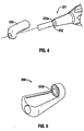
Fig. 4 is a partial perspective view, with parts separated, illustrating the positioning of another embodiment of an adapter on another embodiment of a surgical instrument; -
Fig. 5 is a bottom perspective view of the adapter illustrated inFig. 4 ; and -
Fig. 6 is a perspective of another instrument of the present disclosure. - Embodiments of the presently disclosed surgical instrument are described in detail with reference to the drawings, wherein like reference numerals designate similar or identical elements in each of the several views. In the drawings and the description that follows, the term "proximal" refers to the end of the surgical instrument that is closer to the user, whereas the term "distal" refers to the end of the surgical instrument that is further from the user.
- Referring now to
Figs. 1 and2 , one embodiment of asurgical instrument system 100 is illustrated. Thesurgical instrument system 100 includes asurgical instrument 101, anadapter 130, and anaccessory 120. The instrument illustrated is an endoscopic grasper, by way of example, it being understood that other instruments can also be utilized such as endoscopic scissors, clip appliers, surgical staplers, etc. Thesurgical instrument 101 has ahousing 110, anelongated shaft 112, abase portion 116, and atool assembly 118. Theshaft 112 extends from thehousing 110 andbase portion 116. Thetool assembly 118 is disposed on the distal end portion of theshaft 112. Thebase portion 116 is disposed at a proximal end portion ofshaft 112. - The
surgical instrument 110 includes one ormore contacts 115. In the illustrated embodiment, tworing contacts 115 are shown by way of example. Thecontacts 115 may be positioned on theshaft 112. Thecontacts 115 may include contact buttons, slip rings, or any other suitable connection. Thecontacts 115 are electrically coupled to theadapter 130, which contains an energy storage device, e.g., via one or more wires extending therebetween (through the shaft 112) and/or a wireless connection such that the energy storage device transmits power to thecontacts 115. Thecontacts 115 are engaged by thecontacts 124 of theaccessory 120. In this manner, the power is transmitted to theaccessory 120 from theadapter 130 through thecontacts - Referring now to
Fig. 1A , theaccessory 120 is mountable, and preferably removably mountable, to thesurgical instrument 110. Theaccessory 120 defines achannel 122 therethrough and includes one ormore contacts 124. Thechannel 122 is configured and dimensioned to accommodate at least a portion of theshaft 112 when theaccessory 120 is selectively operably coupled to thesurgical instrument 110. Thus, theaccessory 120 can frictionally engage theshaft 112. Alternatively, the accessory can be attached to the shaft by a snap fit, interlocking structure or by other methods. Thecontacts 124 may be positioned within thechannel 122 such that when theaccessory 120 is positioned on theshaft 112adjacent contacts 115, two or more contacts (i.e., at least onecontact 115 and at least one contact 124) are engaged so that theaccessory 120 is electrically coupled to the energy device ofadapter 130. In particular, thecontacts 124 may be operably coupled to the energy device via any suitable electrical or electromechanical features. For example, these features, which may include wired or wireless connections, may have inductive components, capacitive components, resistive components, switching components, etc. that facilitate the connection between theaccessory 120 and thesurgical instrument 110 so that theaccessory 120 can be powered by the energy device ofadapter 130. Furthermore, thecontacts 124 may include contact buttons, slip rings, or any other suitable connection components. - As illustrated in
Fig. 2 , theadapter 130 may be selectively operably coupled to theshaft 112 and/or thebase portion 116 of thesurgical instrument 100. In alternate embodiments, theadapter 130 is configured and dimensioned to couple to the housing of the surgical instrument. The adapter in some embodiments can be removably coupled to the instrument. As discussed above, theadapter 130 contains an energy storage device (e.g., a battery or any other suitable self-contained electrical energy source) that provides power/energy to the accessory 120 (e.g., via a wired and/or wireless connection). - It should be appreciated that other energy sources for powering the
accessory 120 may also be stored in theadapter 130. Theaccessory 120 may be operably coupled to one or both of theadapter 130 and the surgical instrument 100 (e.g., theshaft 112, thehousing 110, and/or the base portion 116). Theaccessory 120 may include one or more powered devices including cameras, illumination devices, or any other suitable powered device that could assist the clinician in performing a medical procedure. - The
base portion 116 is configured and dimensioned to receive and engage theadapter 130 such that theadapter 130 transmits power to thebase portion 116 for providing power to theaccessory 120. Thebase portion 116 is operably coupled to theaccessory 120. In this manner, thebase portion 116 transmits power from the energy storage device, through theadapter 130, and to theaccessory 120. - As illustrated in
Figs. 2 and 3 , thebase portion 116 includes one ormore contact buttons 116a and theadapter 130 includes one ormore contact buttons 132. The one ormore contact buttons 132 of theadapter 130 and the one ormore contact buttons 116a of thebase portion 116 are configured and dimensioned to engage one another to transmit the power from the energy storage device to theaccessory 120. Theadapter 130 slidably couples onto theshaft 112 such that thecontact buttons adapter 130 can attach to theshaft 112 by a frictional fit, snap fit or by other methods. Theadapter 130 defines anenergy storage housing 134 for positioning the energy storage device therein. Theenergy storage housing 134 facilitates the transmission of power from the energy storage device through thecontact buttons contact buttons contact buttons energy storage housing 134. Note in the illustrated embodiments,contact buttons 116a are positioned proximally of the moredistal contacts 115. - Referring now to
Figs. 4 and 5 , another embodiment of asurgical instrument 201 andadapter 230 are illustrated. In this embodiment, theadapter 230 is operably coupled to thesurgical instrument 201 via aslip ring arrangement 232 in order to transmit power from the energy storage device to theaccessory 120. In this manner, aring 233a may be positioned on theshaft 112 that engages an innerannular surface 233b of theadapter 230 to facilitate the transmission of power therethrough to provide power to theaccessory 120. - In the embodiment of
Figure 6 , adapter 130' can be attached torod 212adjacent base portion 216. An accessory, such asaccessory 120 ofFigure 2 , can be mounted to engage thecontacts 215 positioned onrod 212.Contacts 215 can be wired to the energy storage device in adapter 130' in the same manner as inFigure 1 to supply energy to theaccessory 120 when mounted to therod 212. In this manner a simple device for inserting an accessory, e.g. a camera, into a body cavity is provided. - While several embodiments of the disclosure have been shown in the drawings and/or discussed herein, it is not intended that the disclosure be limited thereto, as it is intended that the disclosure be as broad in scope as the art will allow and that the specification be read likewise. Therefore, the above description should not be construed as limiting, but merely as exemplifications of particular embodiments. Those skilled in the art will envision other modifications within the scope of the claims appended hereto.
Claims (12)
- A surgical instrument system (100) for powering an accessory (120) comprising:a surgical instrument (101) including a housing (110);a shaft (112) extending from the housing;a tool assembly (118) operably coupled to the shaft; andan adapter (230) operably coupled to the surgical instrument, the adapter including an electrical energy storage device to provide electrical power to the accessory when the accessory is operably coupled to the surgical instrument, characterised in that the adapter is electrically operably coupled to the surgical instrument via a slip ring arrangement (232) comprising a ring (233a) adapted to be positioned on the shaft (112) and adapted to engage an inner annular surface (233b) of the adapter (230) to facilitate the transmission of electrical power therethrough in order to transmit the electrical power from the adapter (230) to the accessory (120).
- The surgical instrument system according to claim 1, further comprising an accessory operably couplable to the surgical instrument.
- The surgical instrument system of claim 2, wherein the instrument includes at least one contact adapted to be electrically connect the accessory to the surgical instrument.
- The surgical instrument system according to claim 3, wherein at least one contact is on the shaft of the instrument.
- The surgical instrument system according to any of claims 1-4, wherein the surgical instrument includes a base portion disposed adjacent to at least one of the shaft and the housing, the adapter being adapted to engage the base portion when coupled to the surgical instrument such that the adapter transmits power to the base portion, and the base portion transmits power to the accessory.
- The surgical instrument system according to claim 1, wherein the energy storage device is a battery.
- The surgical instrument system according to claim 6, wherein the adapter defines an energy storage housing for positioning the battery therein.
- The surgical instrument system according to any of claims 1-7, wherein the adapter is slidably coupled to the shaft.
- The surgical instrument system according to any of claims 1-8, wherein the accessory is at least one of a camera and an illumination device.
- The surgical instrument system according to any of claims 1-9, wherein the accessory frictionally engages the shaft.
- The surgical instrument system according to any of claims 1-10, wherein the accessory includes at least one contact to engage a distal contact of the surgical instrument.
- The surgical instrument system according to claim 11, wherein the distal contact is positioned on the shaft.
Applications Claiming Priority (2)
| Application Number | Priority Date | Filing Date | Title |
|---|---|---|---|
| US41211510P | 2010-11-10 | 2010-11-10 | |
| US13/281,569 US20120116368A1 (en) | 2010-11-10 | 2011-10-26 | Surgical instrument with add-on power adapter for accessory |
Publications (3)
| Publication Number | Publication Date |
|---|---|
| EP2452629A2 EP2452629A2 (en) | 2012-05-16 |
| EP2452629A3 EP2452629A3 (en) | 2013-03-13 |
| EP2452629B1 true EP2452629B1 (en) | 2016-03-02 |
Family
ID=44992676
Family Applications (1)
| Application Number | Title | Priority Date | Filing Date |
|---|---|---|---|
| EP11188365.8A Not-in-force EP2452629B1 (en) | 2010-11-10 | 2011-11-09 | Surgical instrument with add-on power adapter for accessory |
Country Status (5)
| Country | Link |
|---|---|
| US (1) | US20120116368A1 (en) |
| EP (1) | EP2452629B1 (en) |
| JP (1) | JP2012101076A (en) |
| AU (1) | AU2011244934A1 (en) |
| CA (1) | CA2756482A1 (en) |
Families Citing this family (129)
| Publication number | Priority date | Publication date | Assignee | Title |
|---|---|---|---|---|
| US10285694B2 (en) | 2001-10-20 | 2019-05-14 | Covidien Lp | Surgical stapler with timer and feedback display |
| US9055943B2 (en) | 2007-09-21 | 2015-06-16 | Covidien Lp | Hand held surgical handle assembly, surgical adapters for use between surgical handle assembly and surgical end effectors, and methods of use |
| US11311291B2 (en) | 2003-10-17 | 2022-04-26 | Covidien Lp | Surgical adapter assemblies for use between surgical handle assembly and surgical end effectors |
| US10022123B2 (en) | 2012-07-09 | 2018-07-17 | Covidien Lp | Surgical adapter assemblies for use between surgical handle assembly and surgical end effectors |
| US10105140B2 (en) | 2009-11-20 | 2018-10-23 | Covidien Lp | Surgical console and hand-held surgical device |
| US7947034B2 (en) | 2004-07-30 | 2011-05-24 | Tyco Healthcare Group Lp | Flexible shaft extender and method of using same |
| US11291443B2 (en) | 2005-06-03 | 2022-04-05 | Covidien Lp | Surgical stapler with timer and feedback display |
| CN102988087B (en) | 2005-07-27 | 2015-09-09 | 柯惠Lp公司 | Such as the axle of electro-mechanical surgical device |
| JP5357161B2 (en) | 2007-09-21 | 2013-12-04 | コヴィディエン リミテッド パートナーシップ | Surgical equipment |
| US8517241B2 (en) | 2010-04-16 | 2013-08-27 | Covidien Lp | Hand-held surgical devices |
| US10498269B2 (en) | 2007-10-05 | 2019-12-03 | Covidien Lp | Powered surgical stapling device |
| US10779818B2 (en) | 2007-10-05 | 2020-09-22 | Covidien Lp | Powered surgical stapling device |
| US8292150B2 (en) | 2010-11-02 | 2012-10-23 | Tyco Healthcare Group Lp | Adapter for powered surgical devices |
| US8603089B2 (en) | 2011-01-19 | 2013-12-10 | Covidien Lp | Surgical instrument including inductively coupled accessory |
| US9549758B2 (en) | 2011-03-23 | 2017-01-24 | Covidien Lp | Surgical access assembly with adapter |
| US11207089B2 (en) | 2011-10-25 | 2021-12-28 | Covidien Lp | Apparatus for endoscopic procedures |
| US9492146B2 (en) | 2011-10-25 | 2016-11-15 | Covidien Lp | Apparatus for endoscopic procedures |
| US9480492B2 (en) | 2011-10-25 | 2016-11-01 | Covidien Lp | Apparatus for endoscopic procedures |
| US9364231B2 (en) | 2011-10-27 | 2016-06-14 | Covidien Lp | System and method of using simulation reload to optimize staple formation |
| US10575716B2 (en) * | 2012-05-11 | 2020-03-03 | Ethicon Llc | Applicator instruments with imaging systems for dispensing surgical fasteners during open repair procedures |
| US10080563B2 (en) | 2012-06-01 | 2018-09-25 | Covidien Lp | Loading unit detection assembly and surgical device for use therewith |
| US9597104B2 (en) | 2012-06-01 | 2017-03-21 | Covidien Lp | Handheld surgical handle assembly, surgical adapters for use between surgical handle assembly and surgical end effectors, and methods of use |
| US9868198B2 (en) | 2012-06-01 | 2018-01-16 | Covidien Lp | Hand held surgical handle assembly, surgical adapters for use between surgical handle assembly and surgical loading units, and methods of use |
| US10492814B2 (en) | 2012-07-09 | 2019-12-03 | Covidien Lp | Apparatus for endoscopic procedures |
| US9839480B2 (en) | 2012-07-09 | 2017-12-12 | Covidien Lp | Surgical adapter assemblies for use between surgical handle assembly and surgical end effectors |
| US9421014B2 (en) | 2012-10-18 | 2016-08-23 | Covidien Lp | Loading unit velocity and position feedback |
| US9782187B2 (en) | 2013-01-18 | 2017-10-10 | Covidien Lp | Adapter load button lockout |
| US10918364B2 (en) | 2013-01-24 | 2021-02-16 | Covidien Lp | Intelligent adapter assembly for use with an electromechanical surgical system |
| US9216013B2 (en) | 2013-02-18 | 2015-12-22 | Covidien Lp | Apparatus for endoscopic procedures |
| US9492189B2 (en) | 2013-03-13 | 2016-11-15 | Covidien Lp | Apparatus for endoscopic procedures |
| US9700318B2 (en) | 2013-04-09 | 2017-07-11 | Covidien Lp | Apparatus for endoscopic procedures |
| US9775610B2 (en) | 2013-04-09 | 2017-10-03 | Covidien Lp | Apparatus for endoscopic procedures |
| US9801646B2 (en) | 2013-05-30 | 2017-10-31 | Covidien Lp | Adapter load button decoupled from loading unit sensor |
| US9797486B2 (en) | 2013-06-20 | 2017-10-24 | Covidien Lp | Adapter direct drive with manual retraction, lockout and connection mechanisms |
| US9629633B2 (en) | 2013-07-09 | 2017-04-25 | Covidien Lp | Surgical device, surgical adapters for use between surgical handle assembly and surgical loading units, and methods of use |
| US9955966B2 (en) | 2013-09-17 | 2018-05-01 | Covidien Lp | Adapter direct drive with manual retraction, lockout, and connection mechanisms for improper use prevention |
| US10271840B2 (en) | 2013-09-18 | 2019-04-30 | Covidien Lp | Apparatus and method for differentiating between tissue and mechanical obstruction in a surgical instrument |
| US9974540B2 (en) | 2013-10-18 | 2018-05-22 | Covidien Lp | Adapter direct drive twist-lock retention mechanism |
| US9295522B2 (en) | 2013-11-08 | 2016-03-29 | Covidien Lp | Medical device adapter with wrist mechanism |
| US10236616B2 (en) | 2013-12-04 | 2019-03-19 | Covidien Lp | Adapter assembly for interconnecting surgical devices and surgical attachments, and surgical systems thereof |
| US9918713B2 (en) | 2013-12-09 | 2018-03-20 | Covidien Lp | Adapter assembly for interconnecting electromechanical surgical devices and surgical loading units, and surgical systems thereof |
| ES2755485T3 (en) | 2013-12-09 | 2020-04-22 | Covidien Lp | Adapter assembly for the interconnection of electromechanical surgical devices and surgical load units, and surgical systems thereof |
| CN110074844B (en) | 2013-12-11 | 2023-02-17 | 柯惠Lp公司 | Wrist assembly and jaw assembly for robotic surgical system |
| US10220522B2 (en) | 2013-12-12 | 2019-03-05 | Covidien Lp | Gear train assemblies for robotic surgical systems |
| US9808245B2 (en) | 2013-12-13 | 2017-11-07 | Covidien Lp | Coupling assembly for interconnecting an adapter assembly and a surgical device, and surgical systems thereof |
| US9839424B2 (en) | 2014-01-17 | 2017-12-12 | Covidien Lp | Electromechanical surgical assembly |
| US10219869B2 (en) | 2014-02-12 | 2019-03-05 | Covidien Lp | Surgical end effectors and pulley assemblies thereof |
| EP2910194A1 (en) * | 2014-02-21 | 2015-08-26 | 3DIntegrated ApS | Surgical instrument |
| WO2015152972A1 (en) | 2014-03-31 | 2015-10-08 | Covidien Lp | Wrist and jaw assemblies for robotic surgical systems |
| US10164466B2 (en) | 2014-04-17 | 2018-12-25 | Covidien Lp | Non-contact surgical adapter electrical interface |
| US10080552B2 (en) | 2014-04-21 | 2018-09-25 | Covidien Lp | Adapter assembly with gimbal for interconnecting electromechanical surgical devices and surgical loading units, and surgical systems thereof |
| US9913643B2 (en) | 2014-05-09 | 2018-03-13 | Covidien Lp | Interlock assemblies for replaceable loading unit |
| US9713466B2 (en) | 2014-05-16 | 2017-07-25 | Covidien Lp | Adaptor for surgical instrument for converting rotary input to linear output |
| US9763661B2 (en) | 2014-06-26 | 2017-09-19 | Covidien Lp | Adapter assembly for interconnecting electromechanical surgical devices and surgical loading units, and surgical systems thereof |
| US9987095B2 (en) | 2014-06-26 | 2018-06-05 | Covidien Lp | Adapter assemblies for interconnecting electromechanical handle assemblies and surgical loading units |
| US10163589B2 (en) | 2014-06-26 | 2018-12-25 | Covidien Lp | Adapter assemblies for interconnecting surgical loading units and handle assemblies |
| US10561418B2 (en) | 2014-06-26 | 2020-02-18 | Covidien Lp | Adapter assemblies for interconnecting surgical loading units and handle assemblies |
| US9839425B2 (en) | 2014-06-26 | 2017-12-12 | Covidien Lp | Adapter assembly for interconnecting electromechanical surgical devices and surgical loading units, and surgical systems thereof |
| US10603128B2 (en) | 2014-10-07 | 2020-03-31 | Covidien Lp | Handheld electromechanical surgical system |
| US10226254B2 (en) | 2014-10-21 | 2019-03-12 | Covidien Lp | Adapter, extension, and connector assemblies for surgical devices |
| US10729443B2 (en) | 2014-10-21 | 2020-08-04 | Covidien Lp | Adapter, extension, and connector assemblies for surgical devices |
| US9949737B2 (en) | 2014-10-22 | 2018-04-24 | Covidien Lp | Adapter assemblies for interconnecting surgical loading units and handle assemblies |
| US10085750B2 (en) | 2014-10-22 | 2018-10-02 | Covidien Lp | Adapter with fire rod J-hook lockout |
| US10111665B2 (en) | 2015-02-19 | 2018-10-30 | Covidien Lp | Electromechanical surgical systems |
| US10226239B2 (en) | 2015-04-10 | 2019-03-12 | Covidien Lp | Adapter assembly with gimbal for interconnecting electromechanical surgical devices and surgical loading units, and surgical systems thereof |
| US10327779B2 (en) | 2015-04-10 | 2019-06-25 | Covidien Lp | Adapter, extension, and connector assemblies for surgical devices |
| US11432902B2 (en) | 2015-04-10 | 2022-09-06 | Covidien Lp | Surgical devices with moisture control |
| JP6755884B2 (en) | 2015-04-22 | 2020-09-16 | コヴィディエン リミテッド パートナーシップ | Handheld electromechanical surgical system |
| US11278286B2 (en) | 2015-04-22 | 2022-03-22 | Covidien Lp | Handheld electromechanical surgical system |
| US10117650B2 (en) | 2015-05-05 | 2018-11-06 | Covidien Lp | Adapter assembly and loading units for surgical stapling devices |
| US10299789B2 (en) | 2015-05-05 | 2019-05-28 | Covidie LP | Adapter assembly for surgical stapling devices |
| US10751058B2 (en) | 2015-07-28 | 2020-08-25 | Covidien Lp | Adapter assemblies for surgical devices |
| EP4252674A3 (en) | 2015-09-25 | 2024-03-20 | Covidien LP | Robotic surgical assemblies and instrument drive connectors thereof |
| US10371238B2 (en) | 2015-10-09 | 2019-08-06 | Covidien Lp | Adapter assembly for surgical device |
| US10413298B2 (en) | 2015-10-14 | 2019-09-17 | Covidien Lp | Adapter assembly for surgical devices |
| US10729435B2 (en) | 2015-11-06 | 2020-08-04 | Covidien Lp | Adapter assemblies for interconnecting surgical loading units and handle assemblies |
| US10939952B2 (en) | 2015-11-06 | 2021-03-09 | Covidien Lp | Adapter, extension, and connector assemblies for surgical devices |
| US10292705B2 (en) | 2015-11-06 | 2019-05-21 | Covidien Lp | Surgical apparatus |
| US10617411B2 (en) | 2015-12-01 | 2020-04-14 | Covidien Lp | Adapter assembly for surgical device |
| US10433841B2 (en) | 2015-12-10 | 2019-10-08 | Covidien Lp | Adapter assembly for surgical device |
| US10420554B2 (en) | 2015-12-22 | 2019-09-24 | Covidien Lp | Personalization of powered surgical devices |
| US10253847B2 (en) | 2015-12-22 | 2019-04-09 | Covidien Lp | Electromechanical surgical devices with single motor drives and adapter assemblies therfor |
| US10314579B2 (en) | 2016-01-07 | 2019-06-11 | Covidien Lp | Adapter assemblies for interconnecting surgical loading units and handle assemblies |
| US10660623B2 (en) | 2016-01-15 | 2020-05-26 | Covidien Lp | Centering mechanism for articulation joint |
| US10508720B2 (en) | 2016-01-21 | 2019-12-17 | Covidien Lp | Adapter assembly with planetary gear drive for interconnecting electromechanical surgical devices and surgical loading units, and surgical systems thereof |
| US10799239B2 (en) | 2016-05-09 | 2020-10-13 | Covidien Lp | Adapter assembly with pulley system and worm gear drive for interconnecting electromechanical surgical devices and surgical end effectors |
| US10736637B2 (en) | 2016-05-10 | 2020-08-11 | Covidien Lp | Brake for adapter assemblies for surgical devices |
| US10588610B2 (en) | 2016-05-10 | 2020-03-17 | Covidien Lp | Adapter assemblies for surgical devices |
| US10702302B2 (en) | 2016-05-17 | 2020-07-07 | Covidien Lp | Adapter assembly including a removable trocar assembly |
| US10463374B2 (en) | 2016-05-17 | 2019-11-05 | Covidien Lp | Adapter assembly for a flexible circular stapler |
| US11191600B2 (en) | 2016-05-26 | 2021-12-07 | Covidien Lp | Robotic surgical assemblies |
| US10653398B2 (en) | 2016-08-05 | 2020-05-19 | Covidien Lp | Adapter assemblies for surgical devices |
| US11116594B2 (en) | 2016-11-08 | 2021-09-14 | Covidien Lp | Surgical systems including adapter assemblies for interconnecting electromechanical surgical devices and end effectors |
| US10631945B2 (en) | 2017-02-28 | 2020-04-28 | Covidien Lp | Autoclavable load sensing device |
| US11272929B2 (en) | 2017-03-03 | 2022-03-15 | Covidien Lp | Dynamically matching input and output shaft speeds of articulating adapter assemblies for surgical instruments |
| US10299790B2 (en) | 2017-03-03 | 2019-05-28 | Covidien Lp | Adapter with centering mechanism for articulation joint |
| US10660641B2 (en) | 2017-03-16 | 2020-05-26 | Covidien Lp | Adapter with centering mechanism for articulation joint |
| US10390858B2 (en) | 2017-05-02 | 2019-08-27 | Covidien Lp | Powered surgical device with speed and current derivative motor shut off |
| US10603035B2 (en) | 2017-05-02 | 2020-03-31 | Covidien Lp | Surgical loading unit including an articulating end effector |
| US11324502B2 (en) | 2017-05-02 | 2022-05-10 | Covidien Lp | Surgical loading unit including an articulating end effector |
| US11311295B2 (en) | 2017-05-15 | 2022-04-26 | Covidien Lp | Adaptive powered stapling algorithm with calibration factor |
| US10772700B2 (en) | 2017-08-23 | 2020-09-15 | Covidien Lp | Contactless loading unit detection |
| EP3678573A4 (en) | 2017-09-06 | 2021-06-02 | Covidien LP | Boundary scaling of surgical robots |
| US11160556B2 (en) | 2018-04-23 | 2021-11-02 | Covidien Lp | Threaded trocar for adapter assemblies |
| US11896230B2 (en) | 2018-05-07 | 2024-02-13 | Covidien Lp | Handheld electromechanical surgical device including load sensor having spherical ball pivots |
| US11534172B2 (en) | 2018-05-07 | 2022-12-27 | Covidien Lp | Electromechanical surgical stapler including trocar assembly release mechanism |
| US11399839B2 (en) | 2018-05-07 | 2022-08-02 | Covidien Lp | Surgical devices including trocar lock and trocar connection indicator |
| US20190388091A1 (en) | 2018-06-21 | 2019-12-26 | Covidien Lp | Powered surgical devices including strain gauges incorporated into flex circuits |
| US11241233B2 (en) | 2018-07-10 | 2022-02-08 | Covidien Lp | Apparatus for ensuring strain gauge accuracy in medical reusable device |
| US11596496B2 (en) | 2018-08-13 | 2023-03-07 | Covidien Lp | Surgical devices with moisture control |
| US11076858B2 (en) | 2018-08-14 | 2021-08-03 | Covidien Lp | Single use electronics for surgical devices |
| US11510669B2 (en) | 2020-09-29 | 2022-11-29 | Covidien Lp | Hand-held surgical instruments |
| US11717276B2 (en) | 2018-10-30 | 2023-08-08 | Covidien Lp | Surgical devices including adapters and seals |
| US11241228B2 (en) | 2019-04-05 | 2022-02-08 | Covidien Lp | Surgical instrument including an adapter assembly and an articulating surgical loading unit |
| US11369378B2 (en) | 2019-04-18 | 2022-06-28 | Covidien Lp | Surgical instrument including an adapter assembly and an articulating surgical loading unit |
| US11446035B2 (en) | 2019-06-24 | 2022-09-20 | Covidien Lp | Retaining mechanisms for trocar assemblies |
| US11426168B2 (en) | 2019-07-05 | 2022-08-30 | Covidien Lp | Trocar coupling assemblies for a surgical stapler |
| US11058429B2 (en) | 2019-06-24 | 2021-07-13 | Covidien Lp | Load sensing assemblies and methods of manufacturing load sensing assemblies |
| US11464541B2 (en) | 2019-06-24 | 2022-10-11 | Covidien Lp | Retaining mechanisms for trocar assembly |
| US11076850B2 (en) | 2019-11-26 | 2021-08-03 | Covidien Lp | Surgical instrument including an adapter assembly and an articulating surgical loading unit |
| US11737747B2 (en) | 2019-12-17 | 2023-08-29 | Covidien Lp | Hand-held surgical instruments |
| US11291446B2 (en) | 2019-12-18 | 2022-04-05 | Covidien Lp | Surgical instrument including an adapter assembly and an articulating surgical loading unit |
| US11583275B2 (en) | 2019-12-27 | 2023-02-21 | Covidien Lp | Surgical instruments including sensor assembly |
| US11504117B2 (en) | 2020-04-02 | 2022-11-22 | Covidien Lp | Hand-held surgical instruments |
| US11660091B2 (en) | 2020-09-08 | 2023-05-30 | Covidien Lp | Surgical device with seal assembly |
| US11571192B2 (en) | 2020-09-25 | 2023-02-07 | Covidien Lp | Adapter assembly for surgical devices |
| US11786248B2 (en) | 2021-07-09 | 2023-10-17 | Covidien Lp | Surgical stapling device including a buttress retention assembly |
| US11819209B2 (en) | 2021-08-03 | 2023-11-21 | Covidien Lp | Hand-held surgical instruments |
| US11862884B2 (en) | 2021-08-16 | 2024-01-02 | Covidien Lp | Surgical instrument with electrical connection |
Family Cites Families (43)
| Publication number | Priority date | Publication date | Assignee | Title |
|---|---|---|---|---|
| US3919541A (en) * | 1974-07-11 | 1975-11-11 | Albert A Chao | Screw driver{3 s light |
| US4542741A (en) * | 1981-07-17 | 1985-09-24 | Burgin Kermit H | Surgical instrument with incorporated lighting system |
| US5211468A (en) * | 1992-09-04 | 1993-05-18 | Jeng Jong Pyng | Screw driver having an illuminating unit mounted thereto |
| US5928137A (en) * | 1996-05-03 | 1999-07-27 | Green; Philip S. | System and method for endoscopic imaging and endosurgery |
| US5873814A (en) * | 1996-07-12 | 1999-02-23 | Adair; Edwin L. | Sterile encapsulated endoscopic video monitor and method |
| US5879289A (en) * | 1996-07-15 | 1999-03-09 | Universal Technologies International, Inc. | Hand-held portable endoscopic camera |
| DE29706249U1 (en) * | 1997-04-08 | 1997-05-22 | Tseng Kuo Hwa | Lighting device on a tool |
| US6029303A (en) * | 1998-03-04 | 2000-02-29 | Dewan; Raman N. | Electronic toothbrush |
| US6116747A (en) * | 1998-05-07 | 2000-09-12 | Design Guidance Inc. | Flashlight |
| US5951142A (en) * | 1998-06-09 | 1999-09-14 | Wang; Scott Chien-Kuo | Adjustable illuminating/retrieving apparatus |
| US5943809A (en) * | 1998-06-10 | 1999-08-31 | Ring; Ronald W. | Fishing pole with light source |
| JP4163296B2 (en) * | 1998-08-07 | 2008-10-08 | オリンパス株式会社 | Endoscope device |
| JP2000254134A (en) * | 1999-03-10 | 2000-09-19 | Olympus Optical Co Ltd | Medical instrument |
| JP2000294224A (en) * | 1999-04-07 | 2000-10-20 | Olympus Optical Co Ltd | Battery and battery-driven surgical operation equipment using the same |
| US8229549B2 (en) * | 2004-07-09 | 2012-07-24 | Tyco Healthcare Group Lp | Surgical imaging device |
| AU6222800A (en) * | 1999-07-20 | 2001-02-05 | Mickey M. Karram | Surgical illumination device and method of use |
| US6562032B1 (en) * | 2001-03-26 | 2003-05-13 | Ellman Alan G | Electrosurgical instrument with vibration |
| ATE398413T1 (en) * | 2001-04-20 | 2008-07-15 | Power Med Interventions Inc | IMAGING DEVICE |
| TW484492U (en) * | 2001-09-26 | 2002-04-21 | Jr-Ching Shie | Aid-lighting for hand tools |
| DE60336303D1 (en) * | 2002-01-30 | 2011-04-21 | Tyco Healthcare | SURGICAL IMAGING DEVICE |
| US8723936B2 (en) * | 2002-03-12 | 2014-05-13 | Karl Storz Imaging, Inc. | Wireless camera coupling with rotatable coupling |
| US7066734B1 (en) * | 2002-08-09 | 2006-06-27 | Ira Jeffrey Cooper | Convertible dental instrument |
| US20060020171A1 (en) * | 2002-10-21 | 2006-01-26 | Gilreath Mark G | Intubation and imaging device and system |
| US7108395B2 (en) * | 2003-04-25 | 2006-09-19 | Carlos Correa | Illumination assembly usable with a plurality of devices |
| US7021790B2 (en) * | 2003-07-22 | 2006-04-04 | Armament Systems & Procedures, Inc. | Miniature LED flashlight with snap-on carrier |
| US20090090763A1 (en) * | 2007-10-05 | 2009-04-09 | Tyco Healthcare Group Lp | Powered surgical stapling device |
| US8251891B2 (en) * | 2004-05-14 | 2012-08-28 | Nathan Moskowitz | Totally wireless electronically embedded action-ended endoscope utilizing differential directional illumination with digitally controlled mirrors and/or prisms |
| US20060004258A1 (en) * | 2004-07-02 | 2006-01-05 | Wei-Zen Sun | Image-type intubation-aiding device |
| US9033870B2 (en) * | 2004-09-24 | 2015-05-19 | Vivid Medical, Inc. | Pluggable vision module and portable display for endoscopy |
| US8029439B2 (en) * | 2005-01-28 | 2011-10-04 | Stryker Corporation | Disposable attachable light source unit for an endoscope |
| US8496647B2 (en) * | 2007-12-18 | 2013-07-30 | Intuitive Surgical Operations, Inc. | Ribbed force sensor |
| US7270439B2 (en) * | 2005-06-13 | 2007-09-18 | Horrell Robin S | Compact lighting system attachable to a surgical tool and method of use thereof |
| DE602006018510D1 (en) * | 2005-10-21 | 2011-01-05 | Stryker Corp | SYSTEM AND METHOD FOR RECHARGING A HARSH ENVIRONMENT EXPOSED BATTERY |
| US7374318B2 (en) * | 2005-11-07 | 2008-05-20 | Nancy Brooks | Lighted tubing |
| US7705559B2 (en) * | 2006-01-27 | 2010-04-27 | Stryker Corporation | Aseptic battery with a removal cell cluster, the cell cluster configured for charging in a socket that receives a sterilizable battery |
| EP2032064A2 (en) * | 2006-06-27 | 2009-03-11 | Palomar Medical Technologies, Inc. | Handheld photocosmetic device |
| EP1913864A1 (en) * | 2006-10-15 | 2008-04-23 | Medic.Nrg Ltd. | Illuminator for medical use |
| DE102008018930A1 (en) * | 2007-04-17 | 2008-11-20 | C2Cure Inc., Wilmington | Electronic component for use in imaging system i.e. camera system, for surgical instrument, has integrated circuit fastened to front side of substrate and electrically connected with continuous lines at front side |
| US8506565B2 (en) * | 2007-08-23 | 2013-08-13 | Covidien Lp | Electrosurgical device with LED adapter |
| US7631981B2 (en) * | 2007-10-15 | 2009-12-15 | Utah Medical Products, Inc. | Disposable medical-examination light |
| US8189043B2 (en) * | 2008-03-07 | 2012-05-29 | Milwaukee Electric Tool Corporation | Hand-held visual inspection device for viewing confined or difficult to access locations |
| US9023071B2 (en) * | 2008-09-12 | 2015-05-05 | Ethicon Endo-Surgery, Inc. | Ultrasonic device for fingertip control |
| US20110058356A1 (en) * | 2009-02-25 | 2011-03-10 | Black & Decker Inc. | Power tool with light emitting assembly |
-
2011
- 2011-10-26 US US13/281,569 patent/US20120116368A1/en not_active Abandoned
- 2011-11-01 CA CA2756482A patent/CA2756482A1/en not_active Abandoned
- 2011-11-02 AU AU2011244934A patent/AU2011244934A1/en not_active Abandoned
- 2011-11-09 JP JP2011245815A patent/JP2012101076A/en active Pending
- 2011-11-09 EP EP11188365.8A patent/EP2452629B1/en not_active Not-in-force
Also Published As
| Publication number | Publication date |
|---|---|
| AU2011244934A1 (en) | 2012-05-24 |
| EP2452629A2 (en) | 2012-05-16 |
| US20120116368A1 (en) | 2012-05-10 |
| CA2756482A1 (en) | 2012-05-10 |
| EP2452629A3 (en) | 2013-03-13 |
| JP2012101076A (en) | 2012-05-31 |
Similar Documents
| Publication | Publication Date | Title |
|---|---|---|
| EP2452629B1 (en) | Surgical instrument with add-on power adapter for accessory | |
| EP3117793A1 (en) | Surgical instrument including accessory powering feature | |
| US10463419B2 (en) | surgical instrument including inductively coupled accessory | |
| US9486268B2 (en) | Battery pack attached to a cable | |
| AU2012253685B2 (en) | Light attachment device for electrosurgical pencil and electrosurgical pencil attachments | |
| WO2005076968A3 (en) | Ultrasonic probe with detachable slidable cauterization forceps | |
| AU2003261638A1 (en) | Endoscope assembly with disposable sheath | |
| WO2005018462A8 (en) | Endoscopic medical instrument and related methods of use | |
| EP1943955A3 (en) | Surgical instrument with wireless communication between control unit and remote sensor | |
| WO2008021716A3 (en) | Morcellator with detachable handle | |
| SG127826A1 (en) | Medical devices for use with endoscope | |
| EP2356949A3 (en) | Surgical instrument with elements to communicate between control unit and end effector | |
| EP3679872B1 (en) | External hand control for surgical power tool | |
| JP2020533077A (en) | Energy cutting for robotic surgical assembly | |
| USD641466S1 (en) | Medical device holster | |
| US20060089622A1 (en) | Inserted molded switch cover for surgical instrument | |
| WO2023101965A3 (en) | Disposable end effectors |
Legal Events
| Date | Code | Title | Description |
|---|---|---|---|
| PUAI | Public reference made under article 153(3) epc to a published international application that has entered the european phase |
Free format text: ORIGINAL CODE: 0009012 |
|
| AK | Designated contracting states |
Kind code of ref document: A2 Designated state(s): AL AT BE BG CH CY CZ DE DK EE ES FI FR GB GR HR HU IE IS IT LI LT LU LV MC MK MT NL NO PL PT RO RS SE SI SK SM TR |
|
| AX | Request for extension of the european patent |
Extension state: BA ME |
|
| RAP1 | Party data changed (applicant data changed or rights of an application transferred) |
Owner name: COVIDIEN LP |
|
| PUAL | Search report despatched |
Free format text: ORIGINAL CODE: 0009013 |
|
| AK | Designated contracting states |
Kind code of ref document: A3 Designated state(s): AL AT BE BG CH CY CZ DE DK EE ES FI FR GB GR HR HU IE IS IT LI LT LU LV MC MK MT NL NO PL PT RO RS SE SI SK SM TR |
|
| AX | Request for extension of the european patent |
Extension state: BA ME |
|
| RIC1 | Information provided on ipc code assigned before grant |
Ipc: A61B 17/00 20060101AFI20130204BHEP Ipc: A61B 19/00 20060101ALI20130204BHEP |
|
| 17P | Request for examination filed |
Effective date: 20130807 |
|
| RBV | Designated contracting states (corrected) |
Designated state(s): AL AT BE BG CH CY CZ DE DK EE ES FI FR GB GR HR HU IE IS IT LI LT LU LV MC MK MT NL NO PL PT RO RS SE SI SK SM TR |
|
| 17Q | First examination report despatched |
Effective date: 20150210 |
|
| GRAP | Despatch of communication of intention to grant a patent |
Free format text: ORIGINAL CODE: EPIDOSNIGR1 |
|
| INTG | Intention to grant announced |
Effective date: 20151022 |
|
| GRAS | Grant fee paid |
Free format text: ORIGINAL CODE: EPIDOSNIGR3 |
|
| GRAA | (expected) grant |
Free format text: ORIGINAL CODE: 0009210 |
|
| RIC1 | Information provided on ipc code assigned before grant |
Ipc: A61B 17/00 20060101AFI20160104BHEP Ipc: A61B 90/30 20160101ALI20160104BHEP |
|
| AK | Designated contracting states |
Kind code of ref document: B1 Designated state(s): AL AT BE BG CH CY CZ DE DK EE ES FI FR GB GR HR HU IE IS IT LI LT LU LV MC MK MT NL NO PL PT RO RS SE SI SK SM TR |
|
| REG | Reference to a national code |
Ref country code: GB Ref legal event code: FG4D |
|
| REG | Reference to a national code |
Ref country code: AT Ref legal event code: REF Ref document number: 777413 Country of ref document: AT Kind code of ref document: T Effective date: 20160315 Ref country code: CH Ref legal event code: EP |
|
| REG | Reference to a national code |
Ref country code: IE Ref legal event code: FG4D |
|
| REG | Reference to a national code |
Ref country code: DE Ref legal event code: R096 Ref document number: 602011023578 Country of ref document: DE |
|
| REG | Reference to a national code |
Ref country code: NL Ref legal event code: MP Effective date: 20160302 |
|
| REG | Reference to a national code |
Ref country code: LT Ref legal event code: MG4D |
|
| REG | Reference to a national code |
Ref country code: AT Ref legal event code: MK05 Ref document number: 777413 Country of ref document: AT Kind code of ref document: T Effective date: 20160302 |
|
| PG25 | Lapsed in a contracting state [announced via postgrant information from national office to epo] |
Ref country code: HR Free format text: LAPSE BECAUSE OF FAILURE TO SUBMIT A TRANSLATION OF THE DESCRIPTION OR TO PAY THE FEE WITHIN THE PRESCRIBED TIME-LIMIT Effective date: 20160302 Ref country code: GR Free format text: LAPSE BECAUSE OF FAILURE TO SUBMIT A TRANSLATION OF THE DESCRIPTION OR TO PAY THE FEE WITHIN THE PRESCRIBED TIME-LIMIT Effective date: 20160603 Ref country code: NO Free format text: LAPSE BECAUSE OF FAILURE TO SUBMIT A TRANSLATION OF THE DESCRIPTION OR TO PAY THE FEE WITHIN THE PRESCRIBED TIME-LIMIT Effective date: 20160602 Ref country code: FI Free format text: LAPSE BECAUSE OF FAILURE TO SUBMIT A TRANSLATION OF THE DESCRIPTION OR TO PAY THE FEE WITHIN THE PRESCRIBED TIME-LIMIT Effective date: 20160302 Ref country code: ES Free format text: LAPSE BECAUSE OF FAILURE TO SUBMIT A TRANSLATION OF THE DESCRIPTION OR TO PAY THE FEE WITHIN THE PRESCRIBED TIME-LIMIT Effective date: 20160302 |
|
| PG25 | Lapsed in a contracting state [announced via postgrant information from national office to epo] |
Ref country code: NL Free format text: LAPSE BECAUSE OF FAILURE TO SUBMIT A TRANSLATION OF THE DESCRIPTION OR TO PAY THE FEE WITHIN THE PRESCRIBED TIME-LIMIT Effective date: 20160302 Ref country code: LV Free format text: LAPSE BECAUSE OF FAILURE TO SUBMIT A TRANSLATION OF THE DESCRIPTION OR TO PAY THE FEE WITHIN THE PRESCRIBED TIME-LIMIT Effective date: 20160302 Ref country code: PL Free format text: LAPSE BECAUSE OF FAILURE TO SUBMIT A TRANSLATION OF THE DESCRIPTION OR TO PAY THE FEE WITHIN THE PRESCRIBED TIME-LIMIT Effective date: 20160302 Ref country code: RS Free format text: LAPSE BECAUSE OF FAILURE TO SUBMIT A TRANSLATION OF THE DESCRIPTION OR TO PAY THE FEE WITHIN THE PRESCRIBED TIME-LIMIT Effective date: 20160302 Ref country code: SE Free format text: LAPSE BECAUSE OF FAILURE TO SUBMIT A TRANSLATION OF THE DESCRIPTION OR TO PAY THE FEE WITHIN THE PRESCRIBED TIME-LIMIT Effective date: 20160302 Ref country code: LT Free format text: LAPSE BECAUSE OF FAILURE TO SUBMIT A TRANSLATION OF THE DESCRIPTION OR TO PAY THE FEE WITHIN THE PRESCRIBED TIME-LIMIT Effective date: 20160302 Ref country code: AT Free format text: LAPSE BECAUSE OF FAILURE TO SUBMIT A TRANSLATION OF THE DESCRIPTION OR TO PAY THE FEE WITHIN THE PRESCRIBED TIME-LIMIT Effective date: 20160302 |
|
| REG | Reference to a national code |
Ref country code: FR Ref legal event code: PLFP Year of fee payment: 6 |
|
| PG25 | Lapsed in a contracting state [announced via postgrant information from national office to epo] |
Ref country code: IS Free format text: LAPSE BECAUSE OF FAILURE TO SUBMIT A TRANSLATION OF THE DESCRIPTION OR TO PAY THE FEE WITHIN THE PRESCRIBED TIME-LIMIT Effective date: 20160702 Ref country code: EE Free format text: LAPSE BECAUSE OF FAILURE TO SUBMIT A TRANSLATION OF THE DESCRIPTION OR TO PAY THE FEE WITHIN THE PRESCRIBED TIME-LIMIT Effective date: 20160302 |
|
| PG25 | Lapsed in a contracting state [announced via postgrant information from national office to epo] |
Ref country code: CZ Free format text: LAPSE BECAUSE OF FAILURE TO SUBMIT A TRANSLATION OF THE DESCRIPTION OR TO PAY THE FEE WITHIN THE PRESCRIBED TIME-LIMIT Effective date: 20160302 Ref country code: SK Free format text: LAPSE BECAUSE OF FAILURE TO SUBMIT A TRANSLATION OF THE DESCRIPTION OR TO PAY THE FEE WITHIN THE PRESCRIBED TIME-LIMIT Effective date: 20160302 Ref country code: PT Free format text: LAPSE BECAUSE OF FAILURE TO SUBMIT A TRANSLATION OF THE DESCRIPTION OR TO PAY THE FEE WITHIN THE PRESCRIBED TIME-LIMIT Effective date: 20160704 Ref country code: SM Free format text: LAPSE BECAUSE OF FAILURE TO SUBMIT A TRANSLATION OF THE DESCRIPTION OR TO PAY THE FEE WITHIN THE PRESCRIBED TIME-LIMIT Effective date: 20160302 Ref country code: RO Free format text: LAPSE BECAUSE OF FAILURE TO SUBMIT A TRANSLATION OF THE DESCRIPTION OR TO PAY THE FEE WITHIN THE PRESCRIBED TIME-LIMIT Effective date: 20160302 |
|
| REG | Reference to a national code |
Ref country code: DE Ref legal event code: R097 Ref document number: 602011023578 Country of ref document: DE |
|
| PG25 | Lapsed in a contracting state [announced via postgrant information from national office to epo] |
Ref country code: BE Free format text: LAPSE BECAUSE OF FAILURE TO SUBMIT A TRANSLATION OF THE DESCRIPTION OR TO PAY THE FEE WITHIN THE PRESCRIBED TIME-LIMIT Effective date: 20160302 Ref country code: IT Free format text: LAPSE BECAUSE OF FAILURE TO SUBMIT A TRANSLATION OF THE DESCRIPTION OR TO PAY THE FEE WITHIN THE PRESCRIBED TIME-LIMIT Effective date: 20160302 |
|
| PLBE | No opposition filed within time limit |
Free format text: ORIGINAL CODE: 0009261 |
|
| STAA | Information on the status of an ep patent application or granted ep patent |
Free format text: STATUS: NO OPPOSITION FILED WITHIN TIME LIMIT |
|
| PG25 | Lapsed in a contracting state [announced via postgrant information from national office to epo] |
Ref country code: DK Free format text: LAPSE BECAUSE OF FAILURE TO SUBMIT A TRANSLATION OF THE DESCRIPTION OR TO PAY THE FEE WITHIN THE PRESCRIBED TIME-LIMIT Effective date: 20160302 |
|
| PGFP | Annual fee paid to national office [announced via postgrant information from national office to epo] |
Ref country code: DE Payment date: 20161020 Year of fee payment: 6 Ref country code: GB Payment date: 20161027 Year of fee payment: 6 Ref country code: FR Payment date: 20161024 Year of fee payment: 6 Ref country code: IE Payment date: 20161024 Year of fee payment: 6 |
|
| 26N | No opposition filed |
Effective date: 20161205 |
|
| PG25 | Lapsed in a contracting state [announced via postgrant information from national office to epo] |
Ref country code: SI Free format text: LAPSE BECAUSE OF FAILURE TO SUBMIT A TRANSLATION OF THE DESCRIPTION OR TO PAY THE FEE WITHIN THE PRESCRIBED TIME-LIMIT Effective date: 20160302 Ref country code: BG Free format text: LAPSE BECAUSE OF FAILURE TO SUBMIT A TRANSLATION OF THE DESCRIPTION OR TO PAY THE FEE WITHIN THE PRESCRIBED TIME-LIMIT Effective date: 20160602 |
|
| REG | Reference to a national code |
Ref country code: CH Ref legal event code: PL |
|
| PG25 | Lapsed in a contracting state [announced via postgrant information from national office to epo] |
Ref country code: CH Free format text: LAPSE BECAUSE OF NON-PAYMENT OF DUE FEES Effective date: 20161130 Ref country code: LI Free format text: LAPSE BECAUSE OF NON-PAYMENT OF DUE FEES Effective date: 20161130 |
|
| PG25 | Lapsed in a contracting state [announced via postgrant information from national office to epo] |
Ref country code: LU Free format text: LAPSE BECAUSE OF NON-PAYMENT OF DUE FEES Effective date: 20161130 |
|
| PG25 | Lapsed in a contracting state [announced via postgrant information from national office to epo] |
Ref country code: HU Free format text: LAPSE BECAUSE OF FAILURE TO SUBMIT A TRANSLATION OF THE DESCRIPTION OR TO PAY THE FEE WITHIN THE PRESCRIBED TIME-LIMIT; INVALID AB INITIO Effective date: 20111109 Ref country code: CY Free format text: LAPSE BECAUSE OF FAILURE TO SUBMIT A TRANSLATION OF THE DESCRIPTION OR TO PAY THE FEE WITHIN THE PRESCRIBED TIME-LIMIT Effective date: 20160302 |
|
| REG | Reference to a national code |
Ref country code: DE Ref legal event code: R119 Ref document number: 602011023578 Country of ref document: DE |
|
| PG25 | Lapsed in a contracting state [announced via postgrant information from national office to epo] |
Ref country code: MK Free format text: LAPSE BECAUSE OF FAILURE TO SUBMIT A TRANSLATION OF THE DESCRIPTION OR TO PAY THE FEE WITHIN THE PRESCRIBED TIME-LIMIT Effective date: 20160302 Ref country code: MC Free format text: LAPSE BECAUSE OF FAILURE TO SUBMIT A TRANSLATION OF THE DESCRIPTION OR TO PAY THE FEE WITHIN THE PRESCRIBED TIME-LIMIT Effective date: 20160302 Ref country code: TR Free format text: LAPSE BECAUSE OF FAILURE TO SUBMIT A TRANSLATION OF THE DESCRIPTION OR TO PAY THE FEE WITHIN THE PRESCRIBED TIME-LIMIT Effective date: 20160302 |
|
| GBPC | Gb: european patent ceased through non-payment of renewal fee |
Effective date: 20171109 |
|
| REG | Reference to a national code |
Ref country code: FR Ref legal event code: ST Effective date: 20180731 |
|
| REG | Reference to a national code |
Ref country code: IE Ref legal event code: MM4A |
|
| PG25 | Lapsed in a contracting state [announced via postgrant information from national office to epo] |
Ref country code: MT Free format text: LAPSE BECAUSE OF NON-PAYMENT OF DUE FEES Effective date: 20161109 |
|
| PG25 | Lapsed in a contracting state [announced via postgrant information from national office to epo] |
Ref country code: IE Free format text: LAPSE BECAUSE OF NON-PAYMENT OF DUE FEES Effective date: 20171109 Ref country code: DE Free format text: LAPSE BECAUSE OF NON-PAYMENT OF DUE FEES Effective date: 20180602 Ref country code: FR Free format text: LAPSE BECAUSE OF NON-PAYMENT OF DUE FEES Effective date: 20171130 Ref country code: AL Free format text: LAPSE BECAUSE OF FAILURE TO SUBMIT A TRANSLATION OF THE DESCRIPTION OR TO PAY THE FEE WITHIN THE PRESCRIBED TIME-LIMIT Effective date: 20160302 |
|
| PG25 | Lapsed in a contracting state [announced via postgrant information from national office to epo] |
Ref country code: GB Free format text: LAPSE BECAUSE OF NON-PAYMENT OF DUE FEES Effective date: 20171109 |