EP2980970B1 - Magnetic power generator - Google Patents
Magnetic power generator Download PDFInfo
- Publication number
- EP2980970B1 EP2980970B1 EP14775319.8A EP14775319A EP2980970B1 EP 2980970 B1 EP2980970 B1 EP 2980970B1 EP 14775319 A EP14775319 A EP 14775319A EP 2980970 B1 EP2980970 B1 EP 2980970B1
- Authority
- EP
- European Patent Office
- Prior art keywords
- magnetic path
- pole
- power generator
- salient
- salient poles
- Prior art date
- Legal status (The legal status is an assumption and is not a legal conclusion. Google has not performed a legal analysis and makes no representation as to the accuracy of the status listed.)
- Active
Links
- 238000004804 winding Methods 0.000 description 15
- 238000010248 power generation Methods 0.000 description 14
- 230000007423 decrease Effects 0.000 description 12
- 238000010586 diagram Methods 0.000 description 9
- 238000004519 manufacturing process Methods 0.000 description 6
- 238000013459 approach Methods 0.000 description 3
- 230000000694 effects Effects 0.000 description 3
- XEEYBQQBJWHFJM-UHFFFAOYSA-N Iron Chemical compound [Fe] XEEYBQQBJWHFJM-UHFFFAOYSA-N 0.000 description 2
- 230000006872 improvement Effects 0.000 description 2
- 229910000831 Steel Inorganic materials 0.000 description 1
- 230000008021 deposition Effects 0.000 description 1
- 230000007613 environmental effect Effects 0.000 description 1
- 230000004907 flux Effects 0.000 description 1
- 229910052742 iron Inorganic materials 0.000 description 1
- 239000000696 magnetic material Substances 0.000 description 1
- 230000004048 modification Effects 0.000 description 1
- 238000012986 modification Methods 0.000 description 1
- 230000002093 peripheral effect Effects 0.000 description 1
- 230000009467 reduction Effects 0.000 description 1
- 239000007858 starting material Substances 0.000 description 1
- 239000010959 steel Substances 0.000 description 1
Images


Classifications
-
- H—ELECTRICITY
- H02—GENERATION; CONVERSION OR DISTRIBUTION OF ELECTRIC POWER
- H02K—DYNAMO-ELECTRIC MACHINES
- H02K1/00—Details of the magnetic circuit
- H02K1/06—Details of the magnetic circuit characterised by the shape, form or construction
- H02K1/12—Stationary parts of the magnetic circuit
- H02K1/14—Stator cores with salient poles
- H02K1/146—Stator cores with salient poles consisting of a generally annular yoke with salient poles
-
- H—ELECTRICITY
- H02—GENERATION; CONVERSION OR DISTRIBUTION OF ELECTRIC POWER
- H02K—DYNAMO-ELECTRIC MACHINES
- H02K21/00—Synchronous motors having permanent magnets; Synchronous generators having permanent magnets
- H02K21/12—Synchronous motors having permanent magnets; Synchronous generators having permanent magnets with stationary armatures and rotating magnets
- H02K21/22—Synchronous motors having permanent magnets; Synchronous generators having permanent magnets with stationary armatures and rotating magnets with magnets rotating around the armatures, e.g. flywheel magnetos
-
- H—ELECTRICITY
- H02—GENERATION; CONVERSION OR DISTRIBUTION OF ELECTRIC POWER
- H02K—DYNAMO-ELECTRIC MACHINES
- H02K2213/00—Specific aspects, not otherwise provided for and not covered by codes H02K2201/00 - H02K2211/00
- H02K2213/03—Machines characterised by numerical values, ranges, mathematical expressions or similar information
-
- H—ELECTRICITY
- H02—GENERATION; CONVERSION OR DISTRIBUTION OF ELECTRIC POWER
- H02K—DYNAMO-ELECTRIC MACHINES
- H02K29/00—Motors or generators having non-mechanical commutating devices, e.g. discharge tubes or semiconductor devices
- H02K29/03—Motors or generators having non-mechanical commutating devices, e.g. discharge tubes or semiconductor devices with a magnetic circuit specially adapted for avoiding torque ripples or self-starting problems
Definitions
- the present invention relates to a magnetic power generator using a permanent magnet, and more particularly, to a three-phase magnetic power generator connected to an engine of a motorcycle or the like.
- the magnetic power generator As a power generator mounted on a motorcycle, a magnetic power generator capable of obtaining a high output with a simple structure is widely used.
- the magnetic power generator includes a stator around which a coil is wound, and a rotor having a permanent magnet.
- a rotation magnetic field by the permanent magnet crosses the coil, and an electromotive force is generated on the side of the stator.
- Patent Literature 1 discloses a power generator in which a magnetic circuit with a higher output and higher efficiency is adopted.
- the following problems require improvement.
- Patent Literature 1 when the number of magnetic poles is increased to secure the amount of power generation (for example, 20 poles), there is a need for an FET type voltage regulator that can respond to high frequencies. Since the FET type regulator is more expensive than a device using a thyristor, a system cost increases, which causes an increase in product price.
- Patent Literature 2 discloses a power generator in which a disposition angle of the adjacent salient poles having the same phase is made to match a pole arc angle of a permanent magnet, and the disposition angle of the adjacent salient poles of the different phases is set to be narrower than the pole arc angle of the permanent magnet.
- the magnetic power generator of Patent Literature 2 can improve the amount of power generation while maintaining the same size.
- the magnetic power generator of Patent Literature 2 is able to reduce the number of magnetic poles to fewer than 16 while ensuring the amount of power generation. Therefore, it is possible to suppress an increase in system cost by using an inexpensive thyristor type voltage regulator.
- the salient poles of each phase can be uniformly disposed. As a result, it is possible to prevent a decrease in power generation efficiency due to the collapse of the power balance between the phases.
- Patent literature 3 discloses a related magnetic power generator having a salient pole stator, having asymmetric polar extensions.
- Patent Literature 2 can improve the amount of power generation, there is a possibility of lowering the manufacturing efficiency.
- an interval between the adjacent salient poles having different phases is set to be narrower than an interval between the adjacent salient poles having the same phase. Since the interval between the adjacent salient poles is not uniform, when the coil is wound around the salient pole, for example, there is a need for measures such as varying the winding speed for each salient pole. Therefore, in some case, the manufacturing efficiency is lowered.
- An object of the present invention is to provide a magnetic power generator that can prevent a decrease in manufacturing efficiency while achieving a high output and high efficiency of the power generation.
- a magnetic power generator includes a stator and a rotor, the stator has a plurality of salient poles, the salient poles comprising a magnetic path section around which a coil is wound, and a projection section projecting to both sides from a front end portion of the magnetic path section, the rotor is rotatably disposed on an outer circumference or an inner circumference of the stator, and a plurality of permanent magnets are attached to the rotor to face the salient poles in a circumferential direction.
- the salient poles having the same phase are adjacently disposed in the circumferential direction, and a coil having the same phase is wound in series around the adjacently disposed salient poles having the same phase.
- the front end portion comprising a front end part of the magnetic path section and the protrusion section is configured to have a disposition angle between the front end portions having the same phase being equal to or less than a pole arc angle of the permanent magnet, and being greater than the disposition angle of the adjacent front end portions having different phases.
- the magnetic path section of the salient pole adjacent to the salient poles having different poles is disposed on the same phase side of the center line of the front end portion of the salient pole adjacent to the salient pole having the different pole.
- the magnetic path section is set so that the disposition angle between the magnetic path sections having the same phase matches the pole arc angle of the permanent magnet.
- the disposition angle of the magnetic path section is uniform.
- a circumferential length of the front end portion is uniformly set.
- a plurality of salient poles adjacently disposed in the circumferential direction form the same phase, and are disposed at the same electric angle.
- the disposition angle of the front end portion of the salient pole is set to the pole arc angle of the permanent magnets, it is possible to suppress a decrease in power generation efficiency due to collapse of the power balance between the phases. Therefore, it is possible to achieve a high output and high efficiency of the power generator.
- the magnetic path section adjacent to the salient pole having the different phase is disposed in proximity to the magnetic path section having the same phase, it is possible to efficiently perform winding of the coil with respect to the magnetic path section and to prevent a decrease in manufacturing efficiency.
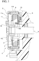
- Fig. 1 is a cross-sectional view illustrating the configuration of a power generator according to a first embodiment of the present invention.
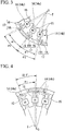
- Fig. 2 is a diagram illustrating the shape and arrangement of a salient pole in the power generator according to the first embodiment of the present invention.
- Fig. 3 is a diagram illustrating a front end portion according to the first embodiment of the present invention.
- Fig. 4 is a diagram illustrating the arrangement of the salient pole according to the first embodiment of the present invention.
- a power generator 1 is a so-called outer rotor type magnet generator.
- the generator 1 is used, for example, as an ACG (AC generator) of a motorcycle.
- the power generator 1 includes a rotor 2 and a stator 3.
- M represents the number of salient poles of the stator 3.
- N represents the number of magnetic poles of a permanent magnet 6 (rotor 2).
- ⁇ p represents a pole arc angle of the permanent magnet 6.
- ⁇ 1 represents a disposition angle of a magnetic path section 15 of the salient pole 14.
- ⁇ 2 represents a disposition angle of a front end portion 17 of the salient pole 14 in the same phase.
- ⁇ p, ⁇ 1 and ⁇ 2 are all mechanical angles.
- O represents the center of rotation of the rotor 2.
- T represents the intersection (deposition center) of the center line between the magnetic path sections 15.
- the rotor 2 is attached to a crankshaft 4 of the engine, and functions as a field element.
- the stator 3 is attached to a housing 5 of the engine, and functions as an armature.
- the permanent magnet 6 is attached to the rotor 2.
- a coil 7 is attached to the stator 3.
- the rotor 2 is rotatably disposed on the outside of the stator 3.
- the rotor 2 includes a rotor yoke 11 and a boss rotor 12 formed of a magnetic material such as an iron.
- the rotor yoke 11 is a bottomed cylindrical member that has a bottom section 11a and a cylindrical section 11b.
- a plurality of permanent magnets 6 are disposed on the inner peripheral surface of the cylindrical section 11b in a circumferential direction.
- the boss rotor 12 is made up of a disk-shaped flange section 12a and a substantially cylindrical boss section 12b.
- the flange section 12a is attached to the center of a bottom section 11a of the rotor yoke 11 to be concentric with the rotor yoke 11.
- a boss section 12b protrudes from the center of the flange section 12a.
- the boss section 12b extends along the center line of the flange section 12a and is coupled to the end portion of a crank shaft 4 via a taper.
- the boss rotor 12 also rotates together with the crank shaft 4, and the rotor 2 rotates on the outside of the coil 7.
- the stator 3 includes a stator core 13 formed by superimposing a plurality of steel plates. A plurality of salient poles 14 are formed in the stator core 13.
- the salient pole 14 is made up of a pillar-shaped magnetic path section 15 around which a coil 7 is wound, and a protrusion section 16 that protrudes from the front end of the magnetic path section 15 in the circumferential direction.
- the part of the salient pole 14 facing the permanent magnet 6 is a front end portion 17.
- the front end portion 17 is made up of a front end part 15t of the magnetic path section 15 and the protrusion section 16.
- the coil 7 is wound around the outer periphery of the magnetic path section 15 of the salient pole 14.
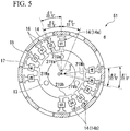
- the power generator 1 generates a three-phase AC. Six of each of the U-, V- and W-phase salient poles 14 are provided. The number M of salient poles of the stator 3 is eighteen. The power generator 1 has a 16-pole 18-pole configuration.
- Fig. 6 illustrates a conventional power generator 90.
- the power generator 90 is a power generator having a configuration described in Patent Literature 2.
- the same members as those of the power generator 1 will be denoted by the same reference numerals.
- U1 to U6 six salient poles 14 forming the U-phase are referred to as U1 to U6.
- six salient poles 14 forming a V-phase are referred to as V1 to V6.
- six salient poles 14 forming a W-phase are referred to as W1 to W6.
- the salient poles 14 having the same phase (e.g., U-phase: U1, U2 and U3) are adjacently arranged in the circumferential direction.
- the coil having the same phase (e.g., U-phase) is wound in series around the adjacent salient poles having the same phase (e.g., U-phase: U1, U2 and U3).
- an angle ⁇ 1 between the magnetic path sections 15 of the salient poles 14 having the same phase is set to match the pole arc angle ⁇ p.
- the angle ⁇ 1 between the magnetic path section 15 of the U2 salient pole 14 and the magnetic path section 15 of the U1 and U3 salient poles 14 is set to 22.5°.
- the angle ⁇ 1 between the magnetic path sections 15 of the salient poles 14 having the same phase is set to be greater than 20.0° that is an angle when uniformly disposing the adjacent salient poles 14 (magnetic path section 15).
- the angle ⁇ 1 is set to match the pole arc angle ⁇ p of the permanent magnet 6.
- the salient pole 14 (salient pole 14b) adjacent to the salient pole 14 having a different phase is disposed at a position (offset position) in which its magnetic path section 15a approaches the salient pole 14 having the same phase (magnetic path section 15).
- the U1 salient pole 14b is adjacent to the magnetic path section 15 of the W6 salient pole 14b, it is disposed at a position in which the magnetic path section 15a approaches the magnetic path section 15 of the U2 salient pole 14a.
- intersection T between the center line L of the magnetic path section 15 of the U2 salient pole 14a and the center line L of the magnetic path section 15 of the U1 salient pole 14b does not match the center of rotation O of the rotor 2.
- the intersection T is located at a position that is spaced (moved) in a direction toward the magnetic path section 15 of the U2 salient pole 14a from the center of rotation O.
- the magnetic path section 15 of the W6 salient pole 14 is disposed at a position that is shifted in an opposite direction to the magnetic path section 15 of the U1 salient pole 14 (parallel movement position).
- the shift amount (parallel movement amount) of the magnetic path section 15 of the salient pole 14b is set so that the entire part between the adjacent magnetic path sections 15 becomes a substantially uniform space.
- the shift amount of the magnetic path section 15 is set in view of the circumferential thickness or radial length of the magnetic path section 15.
- the magnetic path section 15 of the U1 salient pole 14a approaches the magnetic path section 15 of the U2 salient pole 14a, while maintaining the angle ⁇ 1 of 22.5° with respect to the magnetic path section 15 of the U2 salient pole 14b.
- the magnetic path section 15 of the U1 salient pole 14b is separated from the magnetic path section 15 of the W6 salient pole 14b.
- the protrusion sections 16 of the salient pole 14 are disposed on both sides in the circumferential direction with respect to the magnetic path section 15.
- the salient pole 14 having the same protrusion amount of the pair of protrusion sections 16, and the salient pole 14 having the different protrusion amount of the pair of protrusion sections 16 are present.
- the protrusion sections 16 are disposed on both sides in the circumferential direction of the salient poles 14a (e.g., U2, V2, W2 or the like) adjacent only to the salient pole 14 having the same phase.
- the protrusion amounts (the circumferential lengths) of the pair of protrusion sections 16 are the same.
- the U2 pole 14 is adjacent only to the U1 and U3 salient poles 14 having the same phase.
- the protrusion sections 16 of the same projection amount are disposed on both sides in the circumferential direction of the U2 salient pole 14 (magnetic path section 15).
- the protrusion sections 16 are disposed on both sides in the circumferential direction of the salient pole 14b adjacent to the salient pole 14 having the different phase (e.g., U1, V1, W1 or the like).
- the protrusion amount of the pair of protrusion sections 16 (the circumferential lengths) is not uniform.
- the protrusion section 16 disposed at a lateral side adjacent to the salient pole 14 having the different phase is set to be long, and the protrusion section 16 disposed on the lateral side adjacent to the salient pole 14 having the same phase is set to be short.
- the U1 salient pole 14 is adjacent to the W6 salient pole 14 having the different phase.
- the protrusion sections 16 are disposed on both sides in the circumferential direction of the U1 salient pole 14 (magnetic path section 15).
- the protrusion section 16 having the long protrusion amount is disposed on the lateral side adjacent to the W6 salient pole 14 having the different phase.
- the protrusion section 16 having the short protrusion amount is disposed on the lateral side adjacent to the U2 salient pole 14 having the same phase.
- the front end portion 17 is set to have the disposition angle ⁇ 2 of 22.5° in the salient poles 14 having the same phase. That is, the disposition angle ⁇ 2 between the front end portions 17 having the same phase is set to match the pole arc angle ⁇ p of the permanent magnet 6.
- the angle ⁇ 2 between the front end portions 17 having the same phase is an angle between the circumferential center positions of each of the front end portions 17.
- the salient poles 14 of the power generator 1 having the above-described shape and arrangement solves (alleviates) the disadvantages in a conventional generator 90, while maintaining (retaining) the advantages of the conventional generator 90.
- the angle between the magnetic path sections 95 is set to 22.5°.
- the protrusion portions 96 of the salient pole 94 are disposed on both sides in the circumferential direction.
- three salient poles 94 (front end portion 97) forming the same phase face one another so as to be simultaneously positioned in the center line of the magnetic poles of the permanent magnet 6.
- the front end portion 97 of the U1 salient pole 94 faces the N-pole of the permanent magnet 6
- the front end portion 97 of the U2 salient pole 94 faces the S-pole of the permanent magnet 6
- the front end portion 97 of the U3 salient pole 94 faces the N-pole of the permanent magnet 6 simultaneously on the center line of each magnetic pole. Therefore, the power generator 90 can obtain a high power generating efficiency.
- the angle between the magnetic path sections 95 is set to 15.0°.
- the protrusion portions 96 of the salient pole 94 are disposed on both sides in the circumferential direction.
- the space between the magnetic path sections 95 decreases. Therefore, as compared to a location in which the salient poles 94 having the same phase are adjacent to each other, the coil 7 is not easily wound around the magnetic path section 95.
- the angle ⁇ 1 between the magnetic path sections 15 of the salient poles 14 having the same phase is set to match the pole arc angle ⁇ p. Also, among the three salient poles 14 having the same phase, the salient pole 14 (salient pole 14b) adjacent to the salient pole 14 having the different phase is disposed at a location that is shifted so that the magnetic path sections 15 are closer to the salient pole 14a (magnetic path section 15) having the same phase.
- a location of the large space between the magnetic path sections 15 in the stator 3 is not mixed with a location of the small space between the magnetic path sections 15.
- the magnetic path section 15 of the salient pole U3 adjacent to the salient pole 14 having the different pole is disposed at a position closer to the salient pole U2 having the same phase than the center line of the front end portion 17 of the salient pole U3 adjacent to the salient pole 14 having the different pole.
- an area of the slot formed between the U3 magnetic path section 15 and the U2 magnetic path section 15 can be made substantially equal to an area of the slot formed between the U3 magnetic path section 15 and the V1 magnetic path section 15.
- the space between the magnetic path sections 15 in the power generator 1 is substantially uniform. Therefore, it is possible to efficiently wind the coil 7 with respect to each of the salient poles 14 of the stator 3 of the power generator 1 by a winding machine (not illustrated).
- the disposition angle ⁇ 2 between the front end portions 17 of the salient poles 14 having the same phase is set to 22.5°.
- the front end portion 17 of the U1 salient pole 14 faces the N-pole of the permanent magnet 6
- the front end portion 17 of the U2 salient pole 14 faces the S-pole of the permanent magnet 6
- the front end portion 17 of the U3 salient pole 14 faces the N-pole of the permanent magnet 6 simultaneously on the center line of each magnetic pole.
- the disposition angle ⁇ 2 between the front end portions 17 having the same phase is 22.5°, and the disposition angle between the adjacent front end portions 17 having the different phases is 15°.
- the disposition angle ⁇ 2 between the front end portions 17 having the same phase is larger than the disposition angle between the adjacent front end portions 17 having the different phases, since the same electrical angle between the salient poles 14 having the same phase can be obtained, a high efficiency can be attained.
- three salient poles 14 are adjacently disposed in the circumferential direction to form a pole pair 21.
- the U1 salient pole 14, the U2 salient pole 14, and the U3 salient pole 14 are adjacently disposed in the circumferential direction.
- the three salient poles 14 form a U-phase pole pair 21Ua.
- three salient poles 14 in the same phase are disposed at the same electric angle.
- three salient poles 14 face the permanent magnet 6 having the different polarity to have the same electrical angle.
- the front end portions 17 of three salient poles 14 in the pole pair 21 are set at substantially the same angle ⁇ 2 as the pole arc angle ⁇ p of the permanent magnet 6 so that the adjacent salient poles face the magnetic poles having the different polarity.
- the winding directions of the coil 7 wound around the adjacent salient poles 14 are set in mutually opposite directions.
- the winding direction of the coil 7 wound around the U1 salient pole 14 is opposite to the winding direction of the coil 7 wound around the U2 salient pole 14.
- V1, V2 and V3 salient poles 14 forming a V-phase are adjacently disposed to form a pole pair 21Va.
- the W1, W2 and W3 salient poles 14 forming the W-phase are adjacently disposed to form a pole pair 21Wa.
- pole pairs 21Va, 21Wa, V1 to V3 and W1 to W3 face the permanent magnet 6 having the different polarity at the same electrical angle.
- the angle ⁇ 2 between the front end portions 17 of V1 to V3 and W1 to W3 salient poles 14 is set to 22.5°.
- the coil 7 wound in the opposite direction is disposed between the adjacent salient poles 14 in the same phase (V1 and V2, V2 and V3, W1 and W2, W2 and W3).
- a pair of the pole pairs 21 of each phase are provided.
- the two pole pairs 21 are disposed to face each other with the center of rotation O of the rotor 2 interposed therebetween.
- the pole pairs 21Ub are provided at positions of the pole pairs 21Ua facing each other with the center of rotation O interposed therebetween.
- the pole pairs 21Vb and 21Wb are provided in the pole pairs 21Va and 21Wa.
- the three salient poles 14 (U-phase: U4, U5 and U6, V-phase: V4, V5 and V6, and W-phase: W4, W5 and W6) are also located in the pole pairs 21Ub, 21Vb and 21Wb.
- the six salient poles 14 of each phase are uniformly disposed.
- the power balance between the phases does not collapse, and the power generation efficiency is not lowered.
- the power generator 1 is set such that the angle ⁇ 2 between the front end portions 17 of the salient poles 14 having the same phase matches the pole arc angle ⁇ p of the permanent magnet 6. Therefore, it is possible to suppress a decrease in power generation efficiency due to collapse of the power balance between the phases. Therefore, it is possible to achieve a high output and high efficiency of the power generator.
- the power generator 1 is set such that the angle ⁇ 1 between the front end portions 17 of the salient poles 14 having the same phase matches the pole arc angle ⁇ p of the permanent magnet 6, and the magnetic path section 15 of the salient pole 14b adjacent to the salient pole 14 having the different phase is disposed at a position (shifted position) close to the magnetic path section 15 of the salient pole 14a having the same phase. Accordingly, it is possible to secure a sufficient space between the magnetic path sections 15. Therefore, it is possible to effectively perform the winding of the coil 7 with respect to the magnetic path section 15, and it is possible to prevent a decrease in manufacturing efficiency. Also, since it is possible to increase the number of windings of the coil 7 wound around the magnetic path section 15, it is possible to achieve a high output and high efficiency of the power generator 1.
- the salient poles 14 are offset while maintaining the angle of the magnetic path section 15.
- the magnetic path section 15 may deviate from the front end portion 17. That is, when the angle of the magnetic path section 15 is changed, the amount of movement of the root of the magnetic path section 15 is different from the amount of movement of the front end portion of the magnetic path section 15.
- the front end portion of the salient pole 14 deviates from the front end portion 17. That is, in some cases, it is not possible to set the amount of movement of the base at equal intervals merely by changing the angle of the magnetic path section 15.
- the lengths L of the base of the salient pole 14 are almost uniform. Therefore, the space between the adjacent magnetic path sections 15 is substantially uniform. Since the space is substantially uniform, the amount of the coil 7 wound around each salient pole 14 is substantially uniform, the windings of the same specification can be provided at each salient pole 14 (e.g., the winding of the same wire diameter), and it is possible to increase the efficiency. If the amount of the coil 7 wound around each salient pole 14 is substantially uniform, since it is possible to increase the efficiency, there are also cases in which each length L of the base of each salient pole 14 is slightly shifted. For example, there is no problem as long as it is within the range of ⁇ 10 percent.
- the above-described embodiment has been described as a 16-pole 18-pole configuration generator.
- a power generator 51 having a 16-pole 12-pole configuration is also possible.
- the power generator of the present invention is used as a power generator
- the power generator can also be used as a motor.
- the present invention can also be applied to a multi-phase generator such as a five-phase generator.
- the angle ⁇ 1 between the magnetic path sections 15 of the salient pole 14 is not limited to the case of matching the pole arc angle ⁇ p of the permanent magnet 6.
- the angle ⁇ 1 may be set to be greater than the angle (20.0° in the case of 18 poles) in which the magnetic path sections 15 adjacent to each other are uniformly disposed.
- the angle ⁇ 2 between the front end portions 17 having the same phase is not limited to the case of matching the pole arc angle ⁇ p of the permanent magnet 6.
- the angle may be set to be smaller than the pole arc angle ⁇ p in consideration of the winding work of the coil 7 to the magnetic path section 15.
- the disposition angle ⁇ 2 between the front end portions 17 having the same phase is equal to or less than the pole arc angle ⁇ p of the permanent magnet 6, since the interval between the front end portions 17 having the different phase widens, leakage of magnetic flux decreases, and high efficiency is achieved. For this reason, for example, even when the pole arc angle of the permanent magnet 6 is 22.5° and the disposition angle ⁇ 2 between the front end portions 17 having the same phase is 21.5°, the same effect can be obtained.
- the disposition angle ⁇ 2 between the front end portions 17 having the same phase is 22.5°, and the disposition angle between the adjacent front end portions 17 having the different phase is 15°.
- the disposition angle ⁇ 2 between the front end portions 17 having the same phase may be larger than the disposition angle between the adjacent front end portions 17 having the different phase. For example, even when the disposition angle ⁇ 2 between the front end portions 17 having the same phase is 21.5° and the disposition angle between the adjacent front end portions 17 having the different phase is 17°, the same effects can be obtained.
- the disposition angle of the magnetic path sections having the same phase may be set to 20°
- the disposition angle of the adjacent magnetic path sections having the different phase may be set to 20°
- the disposition angle of the front end portions of the salient poles is set to the pole arc angle of the permanent magnet, it is possible to suppress a decrease in power generation efficiency due to collapse of the power balance between the phases. Therefore, it is possible to achieve a high output and high efficiency of the power generator.
- the magnetic path section adjacent to the salient poles having the different phase is located at a position close to the magnetic path section having the same phase, it is possible to efficiently perform winding of the coil with respect to the magnetic path section, and it is possible to prevent a decrease in the manufacturing efficiency.
Landscapes
- Engineering & Computer Science (AREA)
- Power Engineering (AREA)
- Permanent Magnet Type Synchronous Machine (AREA)
- Iron Core Of Rotating Electric Machines (AREA)
Applications Claiming Priority (2)
| Application Number | Priority Date | Filing Date | Title |
|---|---|---|---|
| JP2013063832 | 2013-03-26 | ||
| PCT/JP2014/058008 WO2014157049A1 (ja) | 2013-03-26 | 2014-03-24 | 磁石式発電機 |
Publications (3)
| Publication Number | Publication Date |
|---|---|
| EP2980970A1 EP2980970A1 (en) | 2016-02-03 |
| EP2980970A4 EP2980970A4 (en) | 2017-01-11 |
| EP2980970B1 true EP2980970B1 (en) | 2018-05-30 |
Family
ID=51624024
Family Applications (1)
| Application Number | Title | Priority Date | Filing Date |
|---|---|---|---|
| EP14775319.8A Active EP2980970B1 (en) | 2013-03-26 | 2014-03-24 | Magnetic power generator |
Country Status (4)
| Country | Link |
|---|---|
| EP (1) | EP2980970B1 (ja) |
| JP (1) | JP5668181B1 (ja) |
| CN (1) | CN105191088B (ja) |
| WO (1) | WO2014157049A1 (ja) |
Families Citing this family (2)
| Publication number | Priority date | Publication date | Assignee | Title |
|---|---|---|---|---|
| JP6662740B2 (ja) * | 2016-08-31 | 2020-03-11 | シナノケンシ株式会社 | 三相dcブラシレスモータ |
| JP6616362B2 (ja) * | 2017-09-04 | 2019-12-04 | シナノケンシ株式会社 | ブラシレスモータ及び固定子の巻線方法 |
Family Cites Families (7)
| Publication number | Priority date | Publication date | Assignee | Title |
|---|---|---|---|---|
| GB190605602A (en) * | 1906-03-08 | 1907-03-08 | John Wesley Burleigh | Improvements in the Field Magnets of Dynamo-electric Machines. |
| JP2004215479A (ja) * | 2002-03-29 | 2004-07-29 | Matsushita Electric Ind Co Ltd | モータ |
| US7038348B2 (en) * | 2002-05-16 | 2006-05-02 | Mitsuba Corporation | Dynamo electric machine |
| JP4644530B2 (ja) * | 2005-05-31 | 2011-03-02 | アルファナテクノロジー株式会社 | モータ |
| JP5547924B2 (ja) * | 2008-09-16 | 2014-07-16 | アスモ株式会社 | ブラシレスモータ |
| JP5546224B2 (ja) | 2009-12-07 | 2014-07-09 | 株式会社ミツバ | 磁石式発電機 |
| DE102010044713A1 (de) * | 2010-09-08 | 2012-03-08 | Minebea Co., Ltd. | Bürstenloser Gleichstrommotor |
-
2014
- 2014-03-24 CN CN201480016110.5A patent/CN105191088B/zh active Active
- 2014-03-24 JP JP2014537197A patent/JP5668181B1/ja active Active
- 2014-03-24 WO PCT/JP2014/058008 patent/WO2014157049A1/ja active Application Filing
- 2014-03-24 EP EP14775319.8A patent/EP2980970B1/en active Active
Non-Patent Citations (1)
| Title |
|---|
| None * |
Also Published As
| Publication number | Publication date |
|---|---|
| CN105191088A (zh) | 2015-12-23 |
| EP2980970A1 (en) | 2016-02-03 |
| EP2980970A4 (en) | 2017-01-11 |
| JPWO2014157049A1 (ja) | 2017-02-16 |
| JP5668181B1 (ja) | 2015-02-12 |
| WO2014157049A1 (ja) | 2014-10-02 |
| CN105191088B (zh) | 2017-05-10 |
Similar Documents
| Publication | Publication Date | Title |
|---|---|---|
| JP6977556B2 (ja) | 回転電機 | |
| JP6135982B2 (ja) | モータ | |
| JP6068953B2 (ja) | 電動モータ | |
| US10873226B2 (en) | Rotary electric machine | |
| JP6371947B2 (ja) | モータ | |
| JP2010531130A (ja) | 12個のステータ歯と10個のロータ極とを有する同期モータ | |
| JP2008193785A (ja) | 三相回転電機 | |
| US10637305B2 (en) | Double stator-type rotary machine | |
| JP2012157236A (ja) | ブラシレスモータ及びブラシレスモータの駆動方法 | |
| JP6388611B2 (ja) | ハイブリッド界磁式ダブルギャップ同期機 | |
| WO2003098781A1 (en) | Dynamo electric machine | |
| JP5546224B2 (ja) | 磁石式発電機 | |
| JP2017028847A (ja) | 回転電機の固定子及び回転電機 | |
| JP2014107939A (ja) | ブラシレスモータ | |
| EP2980961B1 (en) | Magnet generator | |
| EP2980970B1 (en) | Magnetic power generator | |
| JP6485486B2 (ja) | 三相モータ | |
| JP2017028972A (ja) | 交流励磁同期回転電機 | |
| JP6399144B2 (ja) | モータ | |
| KR20180043104A (ko) | 모터 | |
| JP2009183095A (ja) | 3相回転電機 | |
| JPWO2018150511A1 (ja) | 回転電機の制御装置、回転電機、および回転電機の制御方法 | |
| JP2013005667A (ja) | シンクロナスリラクタンスモータ |
Legal Events
| Date | Code | Title | Description |
|---|---|---|---|
| PUAI | Public reference made under article 153(3) epc to a published international application that has entered the european phase |
Free format text: ORIGINAL CODE: 0009012 |
|
| 17P | Request for examination filed |
Effective date: 20150921 |
|
| AK | Designated contracting states |
Kind code of ref document: A1 Designated state(s): AL AT BE BG CH CY CZ DE DK EE ES FI FR GB GR HR HU IE IS IT LI LT LU LV MC MK MT NL NO PL PT RO RS SE SI SK SM TR |
|
| AX | Request for extension of the european patent |
Extension state: BA ME |
|
| DAX | Request for extension of the european patent (deleted) | ||
| A4 | Supplementary search report drawn up and despatched |
Effective date: 20161213 |
|
| RIC1 | Information provided on ipc code assigned before grant |
Ipc: H02K 1/16 20060101ALI20161207BHEP Ipc: H02K 21/22 20060101AFI20161207BHEP Ipc: H02K 1/14 20060101ALI20161207BHEP |
|
| GRAP | Despatch of communication of intention to grant a patent |
Free format text: ORIGINAL CODE: EPIDOSNIGR1 |
|
| STAA | Information on the status of an ep patent application or granted ep patent |
Free format text: STATUS: GRANT OF PATENT IS INTENDED |
|
| INTG | Intention to grant announced |
Effective date: 20180117 |
|
| RIN1 | Information on inventor provided before grant (corrected) |
Inventor name: FUKUCHI, TAKESHI Inventor name: KAWAGISHI, MASAKAZU Inventor name: KANBE, MICHIO |
|
| GRAS | Grant fee paid |
Free format text: ORIGINAL CODE: EPIDOSNIGR3 |
|
| GRAA | (expected) grant |
Free format text: ORIGINAL CODE: 0009210 |
|
| STAA | Information on the status of an ep patent application or granted ep patent |
Free format text: STATUS: THE PATENT HAS BEEN GRANTED |
|
| AK | Designated contracting states |
Kind code of ref document: B1 Designated state(s): AL AT BE BG CH CY CZ DE DK EE ES FI FR GB GR HR HU IE IS IT LI LT LU LV MC MK MT NL NO PL PT RO RS SE SI SK SM TR |
|
| RAP1 | Party data changed (applicant data changed or rights of an application transferred) |
Owner name: MITSUBA CORPORATION |
|
| REG | Reference to a national code |
Ref country code: GB Ref legal event code: FG4D |
|
| REG | Reference to a national code |
Ref country code: CH Ref legal event code: EP |
|
| REG | Reference to a national code |
Ref country code: AT Ref legal event code: REF Ref document number: 1004615 Country of ref document: AT Kind code of ref document: T Effective date: 20180615 |
|
| REG | Reference to a national code |
Ref country code: IE Ref legal event code: FG4D |
|
| REG | Reference to a national code |
Ref country code: DE Ref legal event code: R096 Ref document number: 602014026323 Country of ref document: DE |
|
| REG | Reference to a national code |
Ref country code: NL Ref legal event code: MP Effective date: 20180530 |
|
| REG | Reference to a national code |
Ref country code: LT Ref legal event code: MG4D |
|
| PG25 | Lapsed in a contracting state [announced via postgrant information from national office to epo] |
Ref country code: SE Free format text: LAPSE BECAUSE OF FAILURE TO SUBMIT A TRANSLATION OF THE DESCRIPTION OR TO PAY THE FEE WITHIN THE PRESCRIBED TIME-LIMIT Effective date: 20180530 Ref country code: LT Free format text: LAPSE BECAUSE OF FAILURE TO SUBMIT A TRANSLATION OF THE DESCRIPTION OR TO PAY THE FEE WITHIN THE PRESCRIBED TIME-LIMIT Effective date: 20180530 Ref country code: ES Free format text: LAPSE BECAUSE OF FAILURE TO SUBMIT A TRANSLATION OF THE DESCRIPTION OR TO PAY THE FEE WITHIN THE PRESCRIBED TIME-LIMIT Effective date: 20180530 Ref country code: CY Free format text: LAPSE BECAUSE OF FAILURE TO SUBMIT A TRANSLATION OF THE DESCRIPTION OR TO PAY THE FEE WITHIN THE PRESCRIBED TIME-LIMIT Effective date: 20180530 Ref country code: BG Free format text: LAPSE BECAUSE OF FAILURE TO SUBMIT A TRANSLATION OF THE DESCRIPTION OR TO PAY THE FEE WITHIN THE PRESCRIBED TIME-LIMIT Effective date: 20180830 Ref country code: FI Free format text: LAPSE BECAUSE OF FAILURE TO SUBMIT A TRANSLATION OF THE DESCRIPTION OR TO PAY THE FEE WITHIN THE PRESCRIBED TIME-LIMIT Effective date: 20180530 Ref country code: NO Free format text: LAPSE BECAUSE OF FAILURE TO SUBMIT A TRANSLATION OF THE DESCRIPTION OR TO PAY THE FEE WITHIN THE PRESCRIBED TIME-LIMIT Effective date: 20180830 |
|
| PG25 | Lapsed in a contracting state [announced via postgrant information from national office to epo] |
Ref country code: GR Free format text: LAPSE BECAUSE OF FAILURE TO SUBMIT A TRANSLATION OF THE DESCRIPTION OR TO PAY THE FEE WITHIN THE PRESCRIBED TIME-LIMIT Effective date: 20180831 Ref country code: LV Free format text: LAPSE BECAUSE OF FAILURE TO SUBMIT A TRANSLATION OF THE DESCRIPTION OR TO PAY THE FEE WITHIN THE PRESCRIBED TIME-LIMIT Effective date: 20180530 Ref country code: RS Free format text: LAPSE BECAUSE OF FAILURE TO SUBMIT A TRANSLATION OF THE DESCRIPTION OR TO PAY THE FEE WITHIN THE PRESCRIBED TIME-LIMIT Effective date: 20180530 Ref country code: HR Free format text: LAPSE BECAUSE OF FAILURE TO SUBMIT A TRANSLATION OF THE DESCRIPTION OR TO PAY THE FEE WITHIN THE PRESCRIBED TIME-LIMIT Effective date: 20180530 |
|
| REG | Reference to a national code |
Ref country code: AT Ref legal event code: MK05 Ref document number: 1004615 Country of ref document: AT Kind code of ref document: T Effective date: 20180530 |
|
| PG25 | Lapsed in a contracting state [announced via postgrant information from national office to epo] |
Ref country code: NL Free format text: LAPSE BECAUSE OF FAILURE TO SUBMIT A TRANSLATION OF THE DESCRIPTION OR TO PAY THE FEE WITHIN THE PRESCRIBED TIME-LIMIT Effective date: 20180530 |
|
| PG25 | Lapsed in a contracting state [announced via postgrant information from national office to epo] |
Ref country code: CZ Free format text: LAPSE BECAUSE OF FAILURE TO SUBMIT A TRANSLATION OF THE DESCRIPTION OR TO PAY THE FEE WITHIN THE PRESCRIBED TIME-LIMIT Effective date: 20180530 Ref country code: PL Free format text: LAPSE BECAUSE OF FAILURE TO SUBMIT A TRANSLATION OF THE DESCRIPTION OR TO PAY THE FEE WITHIN THE PRESCRIBED TIME-LIMIT Effective date: 20180530 Ref country code: SK Free format text: LAPSE BECAUSE OF FAILURE TO SUBMIT A TRANSLATION OF THE DESCRIPTION OR TO PAY THE FEE WITHIN THE PRESCRIBED TIME-LIMIT Effective date: 20180530 Ref country code: RO Free format text: LAPSE BECAUSE OF FAILURE TO SUBMIT A TRANSLATION OF THE DESCRIPTION OR TO PAY THE FEE WITHIN THE PRESCRIBED TIME-LIMIT Effective date: 20180530 Ref country code: DK Free format text: LAPSE BECAUSE OF FAILURE TO SUBMIT A TRANSLATION OF THE DESCRIPTION OR TO PAY THE FEE WITHIN THE PRESCRIBED TIME-LIMIT Effective date: 20180530 Ref country code: AT Free format text: LAPSE BECAUSE OF FAILURE TO SUBMIT A TRANSLATION OF THE DESCRIPTION OR TO PAY THE FEE WITHIN THE PRESCRIBED TIME-LIMIT Effective date: 20180530 Ref country code: EE Free format text: LAPSE BECAUSE OF FAILURE TO SUBMIT A TRANSLATION OF THE DESCRIPTION OR TO PAY THE FEE WITHIN THE PRESCRIBED TIME-LIMIT Effective date: 20180530 |
|
| PG25 | Lapsed in a contracting state [announced via postgrant information from national office to epo] |
Ref country code: SM Free format text: LAPSE BECAUSE OF FAILURE TO SUBMIT A TRANSLATION OF THE DESCRIPTION OR TO PAY THE FEE WITHIN THE PRESCRIBED TIME-LIMIT Effective date: 20180530 |
|
| REG | Reference to a national code |
Ref country code: DE Ref legal event code: R097 Ref document number: 602014026323 Country of ref document: DE |
|
| PLBE | No opposition filed within time limit |
Free format text: ORIGINAL CODE: 0009261 |
|
| STAA | Information on the status of an ep patent application or granted ep patent |
Free format text: STATUS: NO OPPOSITION FILED WITHIN TIME LIMIT |
|
| 26N | No opposition filed |
Effective date: 20190301 |
|
| PG25 | Lapsed in a contracting state [announced via postgrant information from national office to epo] |
Ref country code: SI Free format text: LAPSE BECAUSE OF FAILURE TO SUBMIT A TRANSLATION OF THE DESCRIPTION OR TO PAY THE FEE WITHIN THE PRESCRIBED TIME-LIMIT Effective date: 20180530 |
|
| REG | Reference to a national code |
Ref country code: DE Ref legal event code: R119 Ref document number: 602014026323 Country of ref document: DE |
|
| PG25 | Lapsed in a contracting state [announced via postgrant information from national office to epo] |
Ref country code: MC Free format text: LAPSE BECAUSE OF FAILURE TO SUBMIT A TRANSLATION OF THE DESCRIPTION OR TO PAY THE FEE WITHIN THE PRESCRIBED TIME-LIMIT Effective date: 20180530 |
|
| REG | Reference to a national code |
Ref country code: CH Ref legal event code: PL |
|
| GBPC | Gb: european patent ceased through non-payment of renewal fee |
Effective date: 20190324 |
|
| PG25 | Lapsed in a contracting state [announced via postgrant information from national office to epo] |
Ref country code: LU Free format text: LAPSE BECAUSE OF NON-PAYMENT OF DUE FEES Effective date: 20190324 Ref country code: AL Free format text: LAPSE BECAUSE OF FAILURE TO SUBMIT A TRANSLATION OF THE DESCRIPTION OR TO PAY THE FEE WITHIN THE PRESCRIBED TIME-LIMIT Effective date: 20180530 |
|
| REG | Reference to a national code |
Ref country code: BE Ref legal event code: MM Effective date: 20190331 |
|
| PG25 | Lapsed in a contracting state [announced via postgrant information from national office to epo] |
Ref country code: DE Free format text: LAPSE BECAUSE OF NON-PAYMENT OF DUE FEES Effective date: 20191001 Ref country code: CH Free format text: LAPSE BECAUSE OF NON-PAYMENT OF DUE FEES Effective date: 20190331 Ref country code: LI Free format text: LAPSE BECAUSE OF NON-PAYMENT OF DUE FEES Effective date: 20190331 Ref country code: GB Free format text: LAPSE BECAUSE OF NON-PAYMENT OF DUE FEES Effective date: 20190324 Ref country code: IE Free format text: LAPSE BECAUSE OF NON-PAYMENT OF DUE FEES Effective date: 20190324 |
|
| PG25 | Lapsed in a contracting state [announced via postgrant information from national office to epo] |
Ref country code: FR Free format text: LAPSE BECAUSE OF NON-PAYMENT OF DUE FEES Effective date: 20190331 Ref country code: BE Free format text: LAPSE BECAUSE OF NON-PAYMENT OF DUE FEES Effective date: 20190331 |
|
| PG25 | Lapsed in a contracting state [announced via postgrant information from national office to epo] |
Ref country code: TR Free format text: LAPSE BECAUSE OF FAILURE TO SUBMIT A TRANSLATION OF THE DESCRIPTION OR TO PAY THE FEE WITHIN THE PRESCRIBED TIME-LIMIT Effective date: 20180530 |
|
| PG25 | Lapsed in a contracting state [announced via postgrant information from national office to epo] |
Ref country code: PT Free format text: LAPSE BECAUSE OF FAILURE TO SUBMIT A TRANSLATION OF THE DESCRIPTION OR TO PAY THE FEE WITHIN THE PRESCRIBED TIME-LIMIT Effective date: 20181001 Ref country code: MT Free format text: LAPSE BECAUSE OF NON-PAYMENT OF DUE FEES Effective date: 20190324 |
|
| PG25 | Lapsed in a contracting state [announced via postgrant information from national office to epo] |
Ref country code: IS Free format text: LAPSE BECAUSE OF FAILURE TO SUBMIT A TRANSLATION OF THE DESCRIPTION OR TO PAY THE FEE WITHIN THE PRESCRIBED TIME-LIMIT Effective date: 20180930 |
|
| PG25 | Lapsed in a contracting state [announced via postgrant information from national office to epo] |
Ref country code: HU Free format text: LAPSE BECAUSE OF FAILURE TO SUBMIT A TRANSLATION OF THE DESCRIPTION OR TO PAY THE FEE WITHIN THE PRESCRIBED TIME-LIMIT; INVALID AB INITIO Effective date: 20140324 |
|
| PG25 | Lapsed in a contracting state [announced via postgrant information from national office to epo] |
Ref country code: MK Free format text: LAPSE BECAUSE OF FAILURE TO SUBMIT A TRANSLATION OF THE DESCRIPTION OR TO PAY THE FEE WITHIN THE PRESCRIBED TIME-LIMIT Effective date: 20180530 |
|
| PGFP | Annual fee paid to national office [announced via postgrant information from national office to epo] |
Ref country code: IT Payment date: 20240212 Year of fee payment: 11 |