EP2979338B1 - Begrenster druckentlastungsklappe für elektrische anlage, insbesondere mittelspannungsschaltanlage - Google Patents
Begrenster druckentlastungsklappe für elektrische anlage, insbesondere mittelspannungsschaltanlage Download PDFInfo
- Publication number
- EP2979338B1 EP2979338B1 EP14720933.2A EP14720933A EP2979338B1 EP 2979338 B1 EP2979338 B1 EP 2979338B1 EP 14720933 A EP14720933 A EP 14720933A EP 2979338 B1 EP2979338 B1 EP 2979338B1
- Authority
- EP
- European Patent Office
- Prior art keywords
- outlet opening
- relief channel
- shaped edges
- electrical assembly
- pressure
- Prior art date
- Legal status (The legal status is an assumption and is not a legal conclusion. Google has not performed a legal analysis and makes no representation as to the accuracy of the status listed.)
- Active
Links
Images

Classifications
-
- H—ELECTRICITY
- H02—GENERATION; CONVERSION OR DISTRIBUTION OF ELECTRIC POWER
- H02B—BOARDS, SUBSTATIONS OR SWITCHING ARRANGEMENTS FOR THE SUPPLY OR DISTRIBUTION OF ELECTRIC POWER
- H02B13/00—Arrangement of switchgear in which switches are enclosed in, or structurally associated with, a casing, e.g. cubicle
- H02B13/02—Arrangement of switchgear in which switches are enclosed in, or structurally associated with, a casing, e.g. cubicle with metal casing
- H02B13/025—Safety arrangements, e.g. in case of excessive pressure or fire due to electrical defect
-
- H—ELECTRICITY
- H02—GENERATION; CONVERSION OR DISTRIBUTION OF ELECTRIC POWER
- H02B—BOARDS, SUBSTATIONS OR SWITCHING ARRANGEMENTS FOR THE SUPPLY OR DISTRIBUTION OF ELECTRIC POWER
- H02B1/00—Frameworks, boards, panels, desks, casings; Details of substations or switching arrangements
- H02B1/56—Cooling; Ventilation
- H02B1/565—Cooling; Ventilation for cabinets
Definitions
- the invention relates to an electrical system, in particular medium-voltage switchgear, with at least one encapsulated functional module and extending parallel to a front side of the electrical system, each end closed pressure relief channel with at least one bottom inlet opening for connection of the respective functional module with the pressure relief channel and at least one outlet opening, which is covered by a mounted on the electrical system or the pressure relief channel with a predetermined bending baffle.
- Such an electrical system is from the EP 2109924 B1 known and has a baffle plate with a predetermined bending point for covering an outlet opening of the pressure relief channel of the medium-voltage switchgear.
- the baffle plate releases the outlet by being bent away by the pressurization along the predetermined bending point upwards, so that hot gases, which by such a fault arc and the pressurization occur, and which can be distributed first through the inlet opening in the pressure relief channel, led out of the medium voltage switchgear over the outlet openings up along the baffle without particular, for example, operating personnel who is in front of the switchgear, affected or endangered by such gas leaks can be.
- Object of the present invention is to develop an electrical system of the type mentioned, which has a compact, safe construction and easy production of this movable cover plate. This object is achieved by an electrical system according to claim 1.
- According to the stop means are formed by engaging in pressurization U-shaped edges on side walls of the baffle and other U-shaped edges of boundary walls of the outlet opening.
- Such U-shaped edges on side walls of the baffle and on the boundary walls of the outlet opening form particularly cost-effective and simple stop means, wherein upon pressurization and bending of the baffle along the predetermined bending point, the U-shaped edges of the side walls of the baffle intervene in the U-shaped edges of the boundary walls, in other words, a hooking of the baffle plate in the U-shaped edges of the boundary walls of the outlet opening is realized, which leads to a stop and thus to a limitation of the size of the outlet opening and at the same time by limiting the deflection of the baffle along its predetermined bending point to a Determining the outlet direction for the hot gases from the pressure relief passage leads.
- the U-shaped edges of the side and the boundary walls at least partially interlock in the closed state of the outlet opening.
- a front boundary wall of the outlet opening extends at an angle of at least 30 ° relative to an upper cover of the pressure relief channel upwards.
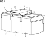
- FIG. 1 shows an electrical system 1 with functional modules 2, 3 and 4 in the form of switch panels of an air-insulated medium voltage switchgear.
- the functional modules 2, 3 and 4 are designed as switch panels of the medium-voltage switchgear and have, for example, figuratively not shown terminal compartments for cable connections, switch rooms for circuit breakers or load switch or the like and busbar rooms.
- Parallel to a front side of the electrical system extends at the top in the embodiment, a respective closed end pressure relief channel 5, which has a figuratively not further apparent bottom inlet opening, through which the function modules 2, 3, 4 are connected to the pressure relief channel 5, in the case of take place at a occurring in the electrical system 1 arc occurring pressurization to distribute the resulting hot gases through the inlet opening in the pressure relief channel 5.
- the pressure relief channel 5 has at least one outlet opening 6, which is covered by a baffle plate 7.
- the baffle plate 7 is fastened by means of a predetermined bending point 8 on the pressure relief channel 5, so that the baffle plate 7 is bent in the event of pressurization from the electrical system 1 and the exiting gases, which first distribute in the pressure relief channel 5, by the pressurization and the Outlet opening releases, as with respect to the FIGS. 1 to 4 explained in more detail below.
- the baffle 7 has side walls 9 and 10, the outlet opening 6 has lateral boundary walls 11 and 12, wherein on the side walls 9 and 10 of the baffle plate 7 and on the lateral boundary walls 11 and 12 of the outlet opening 6 U-shaped edges are provided by the stop means 8 are formed, by which a size of the outlet opening and an outlet direction for the resulting hot pressurized Gases are fixed, as with respect to the FIGS. 2 to 4 is performed.
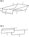
- FIG. 2 shows the baffle 7 with the side walls 9 and 10, which have U-shaped edges 13 and 14, respectively, such that the U-shaped edges 13 and 14 are formed by bending the side walls 9 and 10 inwardly.
- a rear boundary wall 15 is provided for fastening the baffle plate 7 on the pressure relief passage 5, wherein between the rear boundary wall 15 and the baffle plate 7, the predetermined bending point 8 is provided.
- FIG. 3 shows the lateral boundary walls 11 and 12 of the outlet opening 6 in a detailed view, which further U-shaped edges 16 and 17, respectively, which are formed such that the lateral boundary walls 11 and 12 are bent to the outside.
- the lateral boundary walls 11 and 12 are secured to the pressure relief passage 5 at the outlet opening 6 such that the side walls 9 and 10 of the baffle 7 are outside the lateral boundary walls 11 and 12 of the outlet opening 6, wherein in reference to the FIG.
- FIG. 4 shows the electrical system 1 with open outlet port 6 after pressurization by an arc inside the electrical system 1, wherein the deflection plate 7 has bent along the predetermined bending point 8 by the pressurization after distribution of the hot gases in the pressure relief channel 5 up through the stop means in the form of interlocking U-shaped edges 13 and 14, 16 and 17, respectively, a limitation of the bending movement of the baffle plate 7 takes place upwards, and thus a size of the outlet opening and an outlet direction are determined, because the baffle plate 7 does not exceed the position determined by the stop means FIG. 4 can beige to the top, so that hot gases directed directed upward and forward from the pressure relief channel 5 and the outlet port 6 are directed and in particular a threat of operating personnel located in front of the switchgear is effectively prevented.
- FIG. 4 also visible is a front boundary wall 18 of the outlet opening 6, which extends opposite a horizontal cover 19 of the pressure relief channel 5 at an angle upwards, which is at least 30 °, so that through the front boundary wall 18 an additional guidance of the gas flow forward above with respect to the switchgear is ensured, and limited by the front boundary wall 18 and the stop means in its bending baffle 7 a gas flow guide obliquely forward and upward determined from the outlet opening 6, which effectively prevents a risk of befindlichem in the front of the switchgear operator and at the same time the space requirement of Switchgear above the pressure relief channel 5 reduced.
Landscapes
- Engineering & Computer Science (AREA)
- Power Engineering (AREA)
- Gas-Insulated Switchgears (AREA)
- Connections By Means Of Piercing Elements, Nuts, Or Screws (AREA)
- Patch Boards (AREA)
Description
- Die Erfindung betrifft eine elektrische Anlage, insbesondere Mittelspannungsschaltanlage, mit mindestens einem gekapselten Funktionsmodul und einem sich parallel zu einer Frontseite der elektrischen Anlage erstreckenden, jeweils endseitig geschlossenen Druckentlastungskanal mit mindestens einer bodenseitigen Einströmöffnung zur Verbindung des jeweiligen Funktionsmoduls mit dem Druckentlastungskanal und mindestens einer Auslassöffnung, welche mittels einer an der elektrischen Anlage oder dem Druckentlastungskanal mit einer Sollbiegestelle befestigten Ablenkplatte abgedeckt ist.
- Eine derartige elektrische Anlage ist aus der
EP 2109924 B1 bekannt und weist eine Ablenkplatte mit einer Sollbiegestelle zum Abdecken einer Auslassöffnung des Druckentlastungskanals der Mittelspannungsschaltanlage auf. Im Falle einer Druckbeaufschlagung durch einen in der Mittelspannungsschaltanlage auftretenden Störlichtbogen, beispielsweise im Falle eines Kurzschlusses oder dergleichen, gibt die Ablenkplatte die Auslassöffnung frei, indem sie durch die Druckbeaufschlagung entlang der Sollbiegestelle nach oben weggebogen wird, so dass heiße Gase, welche durch einen derartigen Störlichtbogen und die Druckbeaufschlagung entstehen, und die sich zunächst durch die Einströmöffnung im Druckentlastungskanal verteilen, über die Auslassöffnungen nach oben entlang der Ablenkplatte geführt aus der Mittelspannungsschaltanlage entweichen können, ohne dass insbesondere, beispielsweise Bedienungspersonal, welches vor der Schaltanlage steht, durch derartige Gasaustritte beeinträchtigt oder gefährdet werden können. Aus den PublikationenDE1201448B ,DE7138720U ,EP1308973A2 undATA58482A - In einer weiteren vorteilhaften Ausgestaltung der Erfindung greifen die U-förmigen Kanten der Seiten- und der Begrenzungswände im geschlossenen Zustand der Auslassöffnung zumindest teilweise ineinander. Bei einer derartigen Realisierung von auch im geschlossenen Zustand der Auslassöffnung bereits teilweise ineinandergreifenden U-förmigen Kanten der Seitenwände der Ablenkplatte und der Begrenzungswände der Auslassöffnung ist eine sichere Führung der Teile zueinander gewährleistet, so dass im Falle einer Druckbeaufschlagung auch eine sichere Festlegung der Größe der Auslassöffnung wie auch der Auslassrichtung erreichbar ist.
- In einer weiteren vorteilhaften Ausgestaltung der Erfindung erstreckt sich eine Frontbegrenzungswand der Auslassöffnung unter einem Winkel von mindestens 30° gegenüber einer oberen Abdeckung des Druckentlastungskanals nach oben. Durch eine derartig sich nach oben erstreckende Frontbegrenzungswand der Auslassöffnung ist ebenfalls in einfacher Weise eine zusätzliche Gasstromführung im Falle der Druckbeaufschlagung und des Austritts von heißen Gasen nach oben realisiert.
- Die Erfindung wird im Folgenden anhand der Zeichnung und eines Ausführungsbeispiels mit Bezug auf die beiliegenden Figuren näher erläutert. Es zeigen:
- Figur 1:
- Ein Ausführungsbeispiel einer erfindungsgemäßen elektrischen Anlage mit einer geschlossenen Auslassöffnung;
- Figur 2:
- eine Detailansicht des Ausführungsbeispiels der erfindungsgemäßen elektrischen Anlage;
- Figur 3:
- eine weitere Detailansicht des Ausführungsbeispiels der erfindungsgemäßen Anlage; und
- Figur 4:
- das Ausführungsbeispiel der elektrischen Anlage der
Figur 1 mit geöffneter Auslassöffnung. -
Figur 1 zeigt eine elektrische Anlage 1 mit Funktionsmodulen 2, 3 und 4 in Form von Schalterfeldern einer luftisolierten Mittelspannungsschaltanlage. Die Funktionsmodule 2, 3 und 4 sind dabei als Schalterfelder der Mittelspannungsschaltanlage ausgebildet und weisen beispielsweise figürlich nicht weiter dargestellte Anschlussräume für Kabelanschlüsse, Schalterräume für Leistungsschalter oder Lastschalter oder dergleichen sowie Sammelschienenräume auf. Parallel zu einer Frontseite der elektrischen Anlage erstreckt sich oben im Ausführungsbeispiel ein jeweils endseitig geschlossener Druckentlastungskanal 5, welcher über eine figürlich nicht weiter ersichtliche bodenseitige Einströmöffnung verfügt, durch die die Funktionsmodule 2, 3, 4 mit dem Druckentlastungskanal 5 verbunden sind, um im Falle einer bei einem in der elektrischen Anlage 1 auftretenden Störlichtbogen stattfindenden Druckbeaufschlagung die dabei entstehenden heißen Gase über die Einströmöffnung im Druckentlastungskanal 5 zu verteilen. Der Druckentlastungskanal 5 weist mindestens eine Auslassöffnung 6 auf, welche mittels einer Ablenkplatte 7 abgedeckt ist. Die Ablenkplatte 7 ist dabei mittels einer Sollbiegestelle 8 am Druckentlastungskanal 5 befestigt, so dass die Ablenkplatte 7 im Falle einer Druckbeaufschlagung aus der elektrischen Anlage 1 und den austretenden Gasen, welche sich im Druckentlastungskanal 5 zunächst verteilen, durch die Druckbeaufschlagung nach oben gebogen wird und die Auslassöffnung freigibt, wie mit Bezug auf dieFiguren 1 bis 4 im Folgenden näher erläutert. Die Ablenkplatte 7 verfügt über Seitenwände 9 und 10, die Auslassöffnung 6 weist seitliche Begrenzungswände 11 und 12 auf, wobei an den Seitenwänden 9 und 10 der Ablenkplatte 7 sowie an den seitlichen Begrenzungswänden 11 und 12 der Auslassöffnung 6 U-förmige Kanten vorgesehen sind, durch die Anschlagmittel 8 gebildet sind, durch die eine Größe der Auslassöffnung sowie eine Auslassrichtung für die bei Druckbeaufschlagung entstehenden heißen Gase festgelegt sind, wie mit Bezug auf dieFiguren 2 bis 4 ausgeführt wird. -
Figur 2 zeigt die Ablenkplatte 7 mit den Seitenwänden 9 und 10, welche U-förmige Kanten 13 bzw. 14 aufweisen, derart, dass die U-förmigen Kanten 13 und 14 durch Umbiegen der Seitenwände 9 bzw. 10 nach innen gebildet sind. Eine hintere Begrenzungswand 15 ist zur Befestigung der Ablenkplatte 7 am Druckentlastungskanal 5 vorgesehen, wobei zwischen der hinteren Begrenzungswand 15 und der Ablenkplatte 7 die Sollbiegestelle 8 vorgesehen ist. -
Figur 3 zeigt die seitlichen Begrenzungswände 11 und 12 der Auslassöffnung 6 in einer Detailansicht, welche weitere U-förmige Kanten 16 bzw. 17 aufweisen, die derart ausgebildet sind, dass sich die seitlichen Begrenzungswände 11 bzw. 12 nach außen umgebogen sind. Die seitlichen Begrenzungswände 11 bzw. 12 sind dabei am Druckentlastungskanal 5 an der Auslassöffnung 6 derart befestigt, dass die Seitenwände 9 bzw. 10 der Ablenkplatte 7 außerhalb der seitlichen Begrenzungswände 11 bzw. 12 der Auslassöffnung 6 befinden, wobei im mit Bezug auf dieFigur 1 beschriebenen geschlossenen Zustand der Auslassöffnung 6 bei geschlossener Ablenkplatte 7 die U-förmigen Kanten 13 bzw. 14 zumindest teilweise bereits in die U-förmigen Kanten 16 bzw. 17 der seitlichen Begrenzungswände 11 bzw. 12 eingreifen, so dass eine sichere Führung der Ablenkplatte 7 entlang der seitlichen Begrenzungswände 11 bzw. 12 durch die zumindest teilweise ineinander greifenden U-förmigen Kanten 13 bzw. 14 und 16 bzw. 17 gewährleistet ist. -
Figur 4 zeigt die elektrische Anlage 1 mit geöffneter Auslassöffnung 6 nach Druckbeaufschlagung durch einen Störlichtbogen im Inneren der elektrischen Anlage 1, wobei sich durch die Druckbeaufschlagung nach Verteilung der heißen Gase im Druckentlastungskanal 5 die Ablenkplatte 7 entlang der Sollbiegestelle 8 nach oben gebogen hat, bis durch die Anschlagmittel in Form der ineinandergreifenden U-förmigen Kanten 13 und 14 bzw. 16 und 17 eine Begrenzung der Biegebewegung der Ablenkplatte 7 nach oben stattfindet und damit eine Größe der Auslassöffnung sowie eine Auslassrichtung festgelegt sind, weil sich die Ablenkplatte 7 nicht über die durch die Anschlagmittel festgelegte Position derFigur 4 nach oben beigen kann, so dass heiße Gase gerichtet nach oben und nach vorne aus dem Druckentlastungskanal 5 und der Auslassöffnung 6 gerichtet geführt sind und insbesondere eine Gefährdung von vor der Schaltanlage befindlichem Bedienpersonal wirksam verhindert wird. In derFigur 4 ebenfalls erkennbar ist eine Frontbegrenzungswand 18 der Auslassöffnung 6, welche sich gegenüber einer horizontalen Abdeckung 19 des Druckentlastungskanals 5 unter einem Winkel nach oben erstreckt, welcher mindestens 30° beträgt, so dass durch die Frontbegrenzungswand 18 eine zusätzliche Führung des Gasstromes nach vorne oben bezüglich der Schaltanlage gewährleistet ist, und durch die Frontbegrenzungswand 18 und die Anschlagmittel in ihrer Biegung begrenzte Ablenkplatte 7 eine Gasstromführung schräg nach vorne oben aus der Auslassöffnung 6 festgelegt und bestimmt ist, welche eine Gefährdung von im vorderen Bereich der Schaltanlage befindlichem Bedienpersonal wirksam verhindert und gleichzeitig den Raumbedarf der Schaltanlage oberhalb des Druckentlastungskanals 5 reduziert. -
- 1
- elektrische Anlage
- 2, 3, 4
- Funktionsmodule
- 5
- Druckentlastungskanal
- 6
- Auslassöffnung
- 7
- Ablenkplatte
- 8
- Sollbiegestelle
- 9, 10
- Seitenwände
- 11, 12
- Begrenzungswände
- 13, 14
- U-förmige Kanten
- 15
- hintere Begrenzungswand
- 16, 17
- U-förmige Kanten
- 18
- Frontbegrenzungswand
- 19
- obere Abdeckung
Claims (3)
- Elektrische Anlage (1), insbesondere Mittelspannungsschaltanlage, mit mindestens einem gekapselten Funktionsmodul (2, 3, 4) und einem sich parallel zu einer Frontseite der elektrischen Anlage (1) erstreckenden, jeweils endseitig geschlossenen Druckentlastungskanal (5) mit mindestens einer bodenseitigen Einströmöffnung zur Verbindung des jeweiligen Funktionsmoduls (2, 3, 4) mit dem Druckentlastungskanal (5) und mindestens einer Auslassöffnung (6), welche mittels einer an der elektrischen Anlage (1) oder dem Druckentlastungskanal (5) mit einer Sollbiegestelle befestigten Ablenkplatte (7) abgedeckt ist, wobei Anschlagmittel vorgesehen sind, durch welche eine Auslassrichtung festgelegt und eine Größe der Auslassöffnung (6) bestimmt ist,
dadurch gekennzeichnet, d a s s die Anschlagmittel durch bei Druckbeaufschlagung ineinandergreifende U-förmige Kanten (13, 14) an Seitenwänden (9, 10) der Ablenkplatte (7) sowie weitere U-förmige Kanten (16, 17) von Begrenzungswänden (11, 12) der Auslassöffnung (6) gebildet sind. - Elektrische Anlage (1) nach Anspruch 1,
dadurch gekennzeichnet, dass die U-förmigen Kanten (13, 14, 16, 17) der Seitenwände (9, 10) und der Begrenzungswände (11, 12) im geschlossenen Zustand der Auslassöffnung (6) zumindest teilweise ineinander greifen. - Elektrische Anlage (1) nach einem der vorangehenden Ansprüche,
dadurch gekennzeichnet, dass sich eine Frontbegrenzungswand (18) der Auslassöffnung (6) unter einem Winkel von mindestens 30° gegenüber einer oberen Abdeckung (19) des Druckentlastungskanals (5) nach oben erstreckt.
Applications Claiming Priority (2)
| Application Number | Priority Date | Filing Date | Title |
|---|---|---|---|
| DE102013208831.0A DE102013208831B3 (de) | 2013-05-14 | 2013-05-14 | Elektrische Anlage, insbesondere Mittelspannungsschaltanlage |
| PCT/EP2014/058071 WO2014183957A1 (de) | 2013-05-14 | 2014-04-22 | Begrenster druckentlastungsklappe für elektrische anlage, insbesondere mittelspannungsschaltanlage |
Publications (2)
| Publication Number | Publication Date |
|---|---|
| EP2979338A1 EP2979338A1 (de) | 2016-02-03 |
| EP2979338B1 true EP2979338B1 (de) | 2017-07-19 |
Family
ID=50630776
Family Applications (1)
| Application Number | Title | Priority Date | Filing Date |
|---|---|---|---|
| EP14720933.2A Active EP2979338B1 (de) | 2013-05-14 | 2014-04-22 | Begrenster druckentlastungsklappe für elektrische anlage, insbesondere mittelspannungsschaltanlage |
Country Status (5)
| Country | Link |
|---|---|
| EP (1) | EP2979338B1 (de) |
| BR (1) | BR112015028389A2 (de) |
| DE (1) | DE102013208831B3 (de) |
| ES (1) | ES2644351T3 (de) |
| WO (1) | WO2014183957A1 (de) |
Cited By (1)
| Publication number | Priority date | Publication date | Assignee | Title |
|---|---|---|---|---|
| EP4443463A4 (de) * | 2021-11-30 | 2025-03-12 | Mitsubishi Electric Corporation | Aufbewahrungsbox und öffnungs-/schliessvorrichtung |
Families Citing this family (1)
| Publication number | Priority date | Publication date | Assignee | Title |
|---|---|---|---|---|
| FR3065618B1 (fr) * | 2017-04-25 | 2019-12-20 | Alstom Transport Technologies | Capot ameliore pour un coffre electrique et coffre electrique comportant un tel capot |
Family Cites Families (11)
| Publication number | Priority date | Publication date | Assignee | Title |
|---|---|---|---|---|
| DE1201448B (de) * | 1959-09-26 | 1965-09-23 | Siemens Ag | Druckentlastungsklappe fuer Schaltzellen |
| DE7138720U (de) * | 1971-10-13 | 1971-12-30 | Siemens Ag | Allseitig geschlossene elektrische Schaltzelle |
| DE7217567U (de) * | 1972-05-09 | 1972-08-31 | Wickmann Werke Ag | Druckentlastungsvorrichtung für Hochspannungs-Schaltanlagen |
| DE7508952U (de) * | 1975-03-20 | 1975-07-17 | Siemens Ag | Allseitig geschlossene elektrische Schalt zelle |
| AT378631B (de) * | 1982-02-16 | 1985-09-10 | Sprecher & Schuh Ag | Aufklappbare abdeckung fuer die oberseite einer metallgekapselten hochspannungsschaltanlage |
| DE3840239A1 (de) * | 1988-11-29 | 1990-05-31 | Elef Svenska Elverkens Ekonomi | Gekapselte umspannstation |
| DE3840240C2 (de) * | 1988-11-29 | 1998-03-12 | Elef Svenska Elverkens Ekonomi | Druckentlastungsvorrichtung an Gebäuden |
| DE10154903A1 (de) * | 2001-10-30 | 2003-05-15 | Siemens Ag | Elektrischer Leistungsschalter mit einem Gehäusekörper und einem diesen frontseitig abdeckenden Bedienpult |
| JP2004129464A (ja) * | 2002-10-07 | 2004-04-22 | Mitsubishi Electric Corp | 閉鎖型配電盤 |
| DE102007003639B3 (de) * | 2007-01-16 | 2008-03-27 | Siemens Ag | Elektrische Anlage, insbesondere Mittelspannungsschaltanlage |
| DE102007022371A1 (de) * | 2007-05-07 | 2008-11-13 | Siemens Ag | Schottvorrichtung für eine Stromverteilereinheit |
-
2013
- 2013-05-14 DE DE102013208831.0A patent/DE102013208831B3/de not_active Expired - Fee Related
-
2014
- 2014-04-22 WO PCT/EP2014/058071 patent/WO2014183957A1/de not_active Ceased
- 2014-04-22 BR BR112015028389A patent/BR112015028389A2/pt not_active IP Right Cessation
- 2014-04-22 EP EP14720933.2A patent/EP2979338B1/de active Active
- 2014-04-22 ES ES14720933.2T patent/ES2644351T3/es active Active
Non-Patent Citations (1)
| Title |
|---|
| None * |
Cited By (1)
| Publication number | Priority date | Publication date | Assignee | Title |
|---|---|---|---|---|
| EP4443463A4 (de) * | 2021-11-30 | 2025-03-12 | Mitsubishi Electric Corporation | Aufbewahrungsbox und öffnungs-/schliessvorrichtung |
Also Published As
| Publication number | Publication date |
|---|---|
| EP2979338A1 (de) | 2016-02-03 |
| BR112015028389A2 (pt) | 2017-07-25 |
| WO2014183957A1 (de) | 2014-11-20 |
| DE102013208831B3 (de) | 2014-06-18 |
| ES2644351T3 (es) | 2017-11-28 |
Similar Documents
| Publication | Publication Date | Title |
|---|---|---|
| EP2845276B1 (de) | Verschlussvorrichtung für eine schaltanlage | |
| DE102009056190B3 (de) | Lichtbogenlöscheinrichtung und Schaltgerät | |
| DE102010025041A1 (de) | Schalter, insbesondere Lasttrennschalter für Niederspannungen | |
| DE112013004956T5 (de) | Schaltanlage | |
| EP2979338B1 (de) | Begrenster druckentlastungsklappe für elektrische anlage, insbesondere mittelspannungsschaltanlage | |
| DE19645304C2 (de) | Elektrische Anlage für den Mittelspannungsbereich | |
| DE102018206577A1 (de) | Schaltschrank | |
| EP2871731B1 (de) | Entlüftungsanordnung für eine Schaltanlage | |
| EP2109924B1 (de) | Elektrische anlage, insbesondere mittelspannungsschaltanlage | |
| DE102012213969B3 (de) | Schaltanlage | |
| EP1630916A1 (de) | Einspeisesystem für Niederspannungsschaltgeräte | |
| DE202008004009U1 (de) | Verteilergehäuse | |
| DE102008019474A1 (de) | Installationsschaltgerät mit einer Vorrichtung zur Befestigung desselben auf einer Stromschiene | |
| EP2362506B1 (de) | Lichtbogenbegrenzungsvorrichtung | |
| EP2273525B1 (de) | Elektrischer Leistungsschalter | |
| EP4147259B1 (de) | Geräteträger für mindestens einen elektrischen schalter und schaltschrank mit solch einem geräteträger | |
| EP2274809B1 (de) | Schaltanlage, insbesondere mittelspannungs-schaltanlage | |
| DE102014017952A1 (de) | Brennstoffzellenanordnung | |
| DE202010005246U1 (de) | Gasisolierter Mittelspannungstrennschalter | |
| DE202014001922U1 (de) | GIS-Klemmenkasten | |
| DE202017103880U1 (de) | Modulares Druckausleitsystem | |
| DE102005056189B4 (de) | Elektrische Anlage, insbesondere Mittelspannungsschaltanlage und Druckentlastungskanal für eine solche Anlage | |
| AT413167B (de) | Elektrische anlage, insbesondere für den mittelspannungsbereich, mit als teilkanäle ausgebildeten druckentlastungshilfskanälen | |
| DE102014214815B3 (de) | Mittel zum Ausleiten eines Überdrucks aus dem Gehäuse einer Abgangseinheit eines Stromschienensystems und Stromschienensystem | |
| DE733675C (de) | Geschlossene Hochleistungssicherung mit Anschlussfahnen |
Legal Events
| Date | Code | Title | Description |
|---|---|---|---|
| PUAI | Public reference made under article 153(3) epc to a published international application that has entered the european phase |
Free format text: ORIGINAL CODE: 0009012 |
|
| 17P | Request for examination filed |
Effective date: 20151026 |
|
| AK | Designated contracting states |
Kind code of ref document: A1 Designated state(s): AL AT BE BG CH CY CZ DE DK EE ES FI FR GB GR HR HU IE IS IT LI LT LU LV MC MK MT NL NO PL PT RO RS SE SI SK SM TR |
|
| AX | Request for extension of the european patent |
Extension state: BA ME |
|
| DAX | Request for extension of the european patent (deleted) | ||
| GRAP | Despatch of communication of intention to grant a patent |
Free format text: ORIGINAL CODE: EPIDOSNIGR1 |
|
| INTG | Intention to grant announced |
Effective date: 20170208 |
|
| GRAS | Grant fee paid |
Free format text: ORIGINAL CODE: EPIDOSNIGR3 |
|
| GRAA | (expected) grant |
Free format text: ORIGINAL CODE: 0009210 |
|
| AK | Designated contracting states |
Kind code of ref document: B1 Designated state(s): AL AT BE BG CH CY CZ DE DK EE ES FI FR GB GR HR HU IE IS IT LI LT LU LV MC MK MT NL NO PL PT RO RS SE SI SK SM TR |
|
| REG | Reference to a national code |
Ref country code: GB Ref legal event code: FG4D Free format text: NOT ENGLISH |
|
| REG | Reference to a national code |
Ref country code: CH Ref legal event code: EP |
|
| REG | Reference to a national code |
Ref country code: IE Ref legal event code: FG4D Free format text: LANGUAGE OF EP DOCUMENT: GERMAN |
|
| REG | Reference to a national code |
Ref country code: AT Ref legal event code: REF Ref document number: 911244 Country of ref document: AT Kind code of ref document: T Effective date: 20170815 |
|
| RAP2 | Party data changed (patent owner data changed or rights of a patent transferred) |
Owner name: SIEMENS AKTIENGESELLSCHAFT |
|
| REG | Reference to a national code |
Ref country code: DE Ref legal event code: R096 Ref document number: 502014004664 Country of ref document: DE |
|
| REG | Reference to a national code |
Ref country code: CH Ref legal event code: NV Representative=s name: SIEMENS SCHWEIZ AG, CH Ref country code: CH Ref legal event code: PCOW Free format text: NEW ADDRESS: WERNER-VON-SIEMENS-STRASSE 1, 80333 MUENCHEN (DE) |
|
| REG | Reference to a national code |
Ref country code: NL Ref legal event code: MP Effective date: 20170719 |
|
| REG | Reference to a national code |
Ref country code: ES Ref legal event code: FG2A Ref document number: 2644351 Country of ref document: ES Kind code of ref document: T3 Effective date: 20171128 |
|
| REG | Reference to a national code |
Ref country code: LT Ref legal event code: MG4D |
|
| PG25 | Lapsed in a contracting state [announced via postgrant information from national office to epo] |
Ref country code: NL Free format text: LAPSE BECAUSE OF FAILURE TO SUBMIT A TRANSLATION OF THE DESCRIPTION OR TO PAY THE FEE WITHIN THE PRESCRIBED TIME-LIMIT Effective date: 20170719 Ref country code: HR Free format text: LAPSE BECAUSE OF FAILURE TO SUBMIT A TRANSLATION OF THE DESCRIPTION OR TO PAY THE FEE WITHIN THE PRESCRIBED TIME-LIMIT Effective date: 20170719 Ref country code: FI Free format text: LAPSE BECAUSE OF FAILURE TO SUBMIT A TRANSLATION OF THE DESCRIPTION OR TO PAY THE FEE WITHIN THE PRESCRIBED TIME-LIMIT Effective date: 20170719 Ref country code: SE Free format text: LAPSE BECAUSE OF FAILURE TO SUBMIT A TRANSLATION OF THE DESCRIPTION OR TO PAY THE FEE WITHIN THE PRESCRIBED TIME-LIMIT Effective date: 20170719 Ref country code: LT Free format text: LAPSE BECAUSE OF FAILURE TO SUBMIT A TRANSLATION OF THE DESCRIPTION OR TO PAY THE FEE WITHIN THE PRESCRIBED TIME-LIMIT Effective date: 20170719 Ref country code: NO Free format text: LAPSE BECAUSE OF FAILURE TO SUBMIT A TRANSLATION OF THE DESCRIPTION OR TO PAY THE FEE WITHIN THE PRESCRIBED TIME-LIMIT Effective date: 20171019 |
|
| PG25 | Lapsed in a contracting state [announced via postgrant information from national office to epo] |
Ref country code: RS Free format text: LAPSE BECAUSE OF FAILURE TO SUBMIT A TRANSLATION OF THE DESCRIPTION OR TO PAY THE FEE WITHIN THE PRESCRIBED TIME-LIMIT Effective date: 20170719 Ref country code: GR Free format text: LAPSE BECAUSE OF FAILURE TO SUBMIT A TRANSLATION OF THE DESCRIPTION OR TO PAY THE FEE WITHIN THE PRESCRIBED TIME-LIMIT Effective date: 20171020 Ref country code: BG Free format text: LAPSE BECAUSE OF FAILURE TO SUBMIT A TRANSLATION OF THE DESCRIPTION OR TO PAY THE FEE WITHIN THE PRESCRIBED TIME-LIMIT Effective date: 20171019 Ref country code: PL Free format text: LAPSE BECAUSE OF FAILURE TO SUBMIT A TRANSLATION OF THE DESCRIPTION OR TO PAY THE FEE WITHIN THE PRESCRIBED TIME-LIMIT Effective date: 20170719 Ref country code: LV Free format text: LAPSE BECAUSE OF FAILURE TO SUBMIT A TRANSLATION OF THE DESCRIPTION OR TO PAY THE FEE WITHIN THE PRESCRIBED TIME-LIMIT Effective date: 20170719 Ref country code: IS Free format text: LAPSE BECAUSE OF FAILURE TO SUBMIT A TRANSLATION OF THE DESCRIPTION OR TO PAY THE FEE WITHIN THE PRESCRIBED TIME-LIMIT Effective date: 20171119 |
|
| REG | Reference to a national code |
Ref country code: FR Ref legal event code: PLFP Year of fee payment: 5 |
|
| REG | Reference to a national code |
Ref country code: DE Ref legal event code: R097 Ref document number: 502014004664 Country of ref document: DE |
|
| PG25 | Lapsed in a contracting state [announced via postgrant information from national office to epo] |
Ref country code: RO Free format text: LAPSE BECAUSE OF FAILURE TO SUBMIT A TRANSLATION OF THE DESCRIPTION OR TO PAY THE FEE WITHIN THE PRESCRIBED TIME-LIMIT Effective date: 20170719 Ref country code: DK Free format text: LAPSE BECAUSE OF FAILURE TO SUBMIT A TRANSLATION OF THE DESCRIPTION OR TO PAY THE FEE WITHIN THE PRESCRIBED TIME-LIMIT Effective date: 20170719 |
|
| PLBE | No opposition filed within time limit |
Free format text: ORIGINAL CODE: 0009261 |
|
| STAA | Information on the status of an ep patent application or granted ep patent |
Free format text: STATUS: NO OPPOSITION FILED WITHIN TIME LIMIT |
|
| PG25 | Lapsed in a contracting state [announced via postgrant information from national office to epo] |
Ref country code: EE Free format text: LAPSE BECAUSE OF FAILURE TO SUBMIT A TRANSLATION OF THE DESCRIPTION OR TO PAY THE FEE WITHIN THE PRESCRIBED TIME-LIMIT Effective date: 20170719 Ref country code: SK Free format text: LAPSE BECAUSE OF FAILURE TO SUBMIT A TRANSLATION OF THE DESCRIPTION OR TO PAY THE FEE WITHIN THE PRESCRIBED TIME-LIMIT Effective date: 20170719 Ref country code: SM Free format text: LAPSE BECAUSE OF FAILURE TO SUBMIT A TRANSLATION OF THE DESCRIPTION OR TO PAY THE FEE WITHIN THE PRESCRIBED TIME-LIMIT Effective date: 20170719 |
|
| 26N | No opposition filed |
Effective date: 20180420 |
|
| PG25 | Lapsed in a contracting state [announced via postgrant information from national office to epo] |
Ref country code: SI Free format text: LAPSE BECAUSE OF FAILURE TO SUBMIT A TRANSLATION OF THE DESCRIPTION OR TO PAY THE FEE WITHIN THE PRESCRIBED TIME-LIMIT Effective date: 20170719 |
|
| PGFP | Annual fee paid to national office [announced via postgrant information from national office to epo] |
Ref country code: NL Payment date: 20180528 Year of fee payment: 8 |
|
| PG25 | Lapsed in a contracting state [announced via postgrant information from national office to epo] |
Ref country code: MT Free format text: LAPSE BECAUSE OF FAILURE TO SUBMIT A TRANSLATION OF THE DESCRIPTION OR TO PAY THE FEE WITHIN THE PRESCRIBED TIME-LIMIT Effective date: 20170719 |
|
| PGFP | Annual fee paid to national office [announced via postgrant information from national office to epo] |
Ref country code: ES Payment date: 20180724 Year of fee payment: 5 |
|
| PG25 | Lapsed in a contracting state [announced via postgrant information from national office to epo] |
Ref country code: MC Free format text: LAPSE BECAUSE OF FAILURE TO SUBMIT A TRANSLATION OF THE DESCRIPTION OR TO PAY THE FEE WITHIN THE PRESCRIBED TIME-LIMIT Effective date: 20170719 |
|
| REG | Reference to a national code |
Ref country code: CH Ref legal event code: PL |
|
| REG | Reference to a national code |
Ref country code: BE Ref legal event code: MM Effective date: 20180430 |
|
| GBPC | Gb: european patent ceased through non-payment of renewal fee |
Effective date: 20180422 |
|
| REG | Reference to a national code |
Ref country code: IE Ref legal event code: MM4A |
|
| PG25 | Lapsed in a contracting state [announced via postgrant information from national office to epo] |
Ref country code: LU Free format text: LAPSE BECAUSE OF NON-PAYMENT OF DUE FEES Effective date: 20180422 |
|
| PG25 | Lapsed in a contracting state [announced via postgrant information from national office to epo] |
Ref country code: CH Free format text: LAPSE BECAUSE OF NON-PAYMENT OF DUE FEES Effective date: 20180430 Ref country code: LI Free format text: LAPSE BECAUSE OF NON-PAYMENT OF DUE FEES Effective date: 20180430 Ref country code: GB Free format text: LAPSE BECAUSE OF NON-PAYMENT OF DUE FEES Effective date: 20180422 Ref country code: BE Free format text: LAPSE BECAUSE OF NON-PAYMENT OF DUE FEES Effective date: 20180430 |
|
| PG25 | Lapsed in a contracting state [announced via postgrant information from national office to epo] |
Ref country code: IE Free format text: LAPSE BECAUSE OF NON-PAYMENT OF DUE FEES Effective date: 20180422 |
|
| PG25 | Lapsed in a contracting state [announced via postgrant information from national office to epo] |
Ref country code: FR Free format text: LAPSE BECAUSE OF NON-PAYMENT OF DUE FEES Effective date: 20190430 |
|
| PG25 | Lapsed in a contracting state [announced via postgrant information from national office to epo] |
Ref country code: PT Free format text: LAPSE BECAUSE OF FAILURE TO SUBMIT A TRANSLATION OF THE DESCRIPTION OR TO PAY THE FEE WITHIN THE PRESCRIBED TIME-LIMIT Effective date: 20170719 |
|
| PG25 | Lapsed in a contracting state [announced via postgrant information from national office to epo] |
Ref country code: MK Free format text: LAPSE BECAUSE OF NON-PAYMENT OF DUE FEES Effective date: 20170719 Ref country code: HU Free format text: LAPSE BECAUSE OF FAILURE TO SUBMIT A TRANSLATION OF THE DESCRIPTION OR TO PAY THE FEE WITHIN THE PRESCRIBED TIME-LIMIT; INVALID AB INITIO Effective date: 20140422 Ref country code: CY Free format text: LAPSE BECAUSE OF FAILURE TO SUBMIT A TRANSLATION OF THE DESCRIPTION OR TO PAY THE FEE WITHIN THE PRESCRIBED TIME-LIMIT Effective date: 20170719 |
|
| PG25 | Lapsed in a contracting state [announced via postgrant information from national office to epo] |
Ref country code: AL Free format text: LAPSE BECAUSE OF FAILURE TO SUBMIT A TRANSLATION OF THE DESCRIPTION OR TO PAY THE FEE WITHIN THE PRESCRIBED TIME-LIMIT Effective date: 20170719 |
|
| REG | Reference to a national code |
Ref country code: AT Ref legal event code: MM01 Ref document number: 911244 Country of ref document: AT Kind code of ref document: T Effective date: 20190422 |
|
| REG | Reference to a national code |
Ref country code: ES Ref legal event code: FD2A Effective date: 20200831 |
|
| PG25 | Lapsed in a contracting state [announced via postgrant information from national office to epo] |
Ref country code: ES Free format text: LAPSE BECAUSE OF NON-PAYMENT OF DUE FEES Effective date: 20190423 |
|
| PG25 | Lapsed in a contracting state [announced via postgrant information from national office to epo] |
Ref country code: AT Free format text: LAPSE BECAUSE OF NON-PAYMENT OF DUE FEES Effective date: 20190422 |
|
| PGFP | Annual fee paid to national office [announced via postgrant information from national office to epo] |
Ref country code: DE Payment date: 20250620 Year of fee payment: 12 |
|
| PGFP | Annual fee paid to national office [announced via postgrant information from national office to epo] |
Ref country code: IT Payment date: 20250417 Year of fee payment: 12 |
|
| PGFP | Annual fee paid to national office [announced via postgrant information from national office to epo] |
Ref country code: TR Payment date: 20250415 Year of fee payment: 12 |
|
| PGFP | Annual fee paid to national office [announced via postgrant information from national office to epo] |
Ref country code: CZ Payment date: 20250414 Year of fee payment: 12 |