EP2977532A1 - Außengriffsystem für eine Fahrzeugtür - Google Patents
Außengriffsystem für eine Fahrzeugtür Download PDFInfo
- Publication number
- EP2977532A1 EP2977532A1 EP14382284.9A EP14382284A EP2977532A1 EP 2977532 A1 EP2977532 A1 EP 2977532A1 EP 14382284 A EP14382284 A EP 14382284A EP 2977532 A1 EP2977532 A1 EP 2977532A1
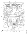
- Authority
- EP
- European Patent Office
- Prior art keywords
- base part
- cap
- handle system
- positive
- locking element
- Prior art date
- Legal status (The legal status is an assumption and is not a legal conclusion. Google has not performed a legal analysis and makes no representation as to the accuracy of the status listed.)
- Granted
Links
Images




Classifications
-
- E—FIXED CONSTRUCTIONS
- E05—LOCKS; KEYS; WINDOW OR DOOR FITTINGS; SAFES
- E05B—LOCKS; ACCESSORIES THEREFOR; HANDCUFFS
- E05B85/00—Details of vehicle locks not provided for in groups E05B77/00 - E05B83/00
- E05B85/10—Handles
- E05B85/14—Handles pivoted about an axis parallel to the wing
- E05B85/16—Handles pivoted about an axis parallel to the wing a longitudinal grip part being pivoted at one end about an axis perpendicular to the longitudinal axis of the grip part
-
- E—FIXED CONSTRUCTIONS
- E05—LOCKS; KEYS; WINDOW OR DOOR FITTINGS; SAFES
- E05B—LOCKS; ACCESSORIES THEREFOR; HANDCUFFS
- E05B79/00—Mounting or connecting vehicle locks or parts thereof
- E05B79/02—Mounting of vehicle locks or parts thereof
- E05B79/06—Mounting of handles, e.g. to the wing or to the lock
Definitions
- the invention relates to an exterior handle system for a vehicle door according to the combination of features of claim 1 of the invention.
- T2 is an outside handle system for a vehicle door, in particular side door, known, which outer handle system on the one hand has an elongated handle main body which extends in the vehicle longitudinal direction (X-direction).
- the handle main body is pivotally mounted at one end to a first base member made of metal.
- the first base member is mounted by means of a screw on an outer surface of the vehicle door.
- the outer handle system has a second base member made of metal, which connects to the pivot bearing opposite end of the handle main body and is also mounted by means of a screw on the outer surface of the vehicle door.
- the object of the invention is to provide an alternative with respect to the state of the art outer handle system for a vehicle door, which is expandable with simple and cost manufacturability and assembly in its function, for example, can be performed alternatively with or without lock cylinder of a door lock.
- an outer handle system for a vehicle door with an elongated handle main body, which in turn is pivotally mounted at one end to a fixed to the vehicle door base member by means of a pivot bearing, and with a pivot bearing side of the handle main body and attached to the base cap, which a receiving opening formed in the base part for an attachment or fitting closes, wherein the cover is secured by mediation of a content Erten on the base part staple element by an adjustable positive locking element on the base part.
- the cap is allowed in alternative embodiment of the outer handle system with a An or fitting, such as a lock cylinder of a door opening and closing mechanism, which lock cylinder occupies the said receiving opening, if such an arrival or Built-in is not desired.
- a built-in or attachment in the form of a door lock cylinder, but covers any arranged in said receiving opening attachment or attachment, for example, a proximity sensor, which is covered by said cap / is.
- the cap is one or two parts formed by a cap support member and a cover member, wherein in assembly the cap support member of the cap on the opposite side of the handle main body of its side wall by the intermediary of the clamping element by the adjustable Positive locking element is attached to the base part.
- the positive-locking element is designed to be spring-loaded in the closing direction, whereby an assembly of the cap is allowed without any auxiliary tool.
- a form-fitting receptacle formed on the cap is assigned to the positive-locking element into which the positive-locking element automatically penetrates in the course of assembly and effects the desired positive locking.
- the positive-locking element is formed by an axially adjustable slide element according to a particularly simple design of the invention.
- the positive locking element in the form of the slider element is formed integrally with the clamping element and axially adjustable due to an elastic design of at least one portion of the clamping element carrying the form-locking element.
- the positive-locking element in the form of the slide element can also be designed as a separate component and guided in an axially adjustable manner in a guide bore of the clamping element.
- the clamp element is preferably frame-shaped and, with the receiving opening in the base part at least partially enclosing, preferably held on the base part by positive locking, in particular latching.
- Fig. 1 first shows a vehicle door 1, in this case a rear left side door of a passenger car, with an outside handle system 2.
- the purposegriffsystem 2 an elongated handle main body 3, which in turn by means of one in the Fig. 4 and 5 pivot bearing 4 shown pivotally mounted on a base part 5 fixed to the vehicle door 1.
- the handle main body 3 is vehicle or door outside in the area of a vehicle-inwardly curved portion or a handle 6 with recess 7 of a door outer part 8, in particular a the outer skin of the vehicle with determining door outer panel arranged, whereas the base part 5 inside door on the door outer part. 8 , in particular door outer panel of the vehicle door 1 is attached.
- the handle main body 3 serves to actuate a door opening and closing mechanism (not shown in the drawing) and is preferably made of a metal and / or plastic.
- the handle main body 3 is designed to be spring-loaded in the pivoting direction by means of a helical torsion spring 9.
- the base part 5 is formed largely plate-shaped with a plurality of stiffening webs 10 and also formed of metal or plastic. It acts essentially as a support member for the handle main body 3 and any other attachment or mounting parts, which will be discussed further below.
- Swivel bearing side ie, according to the Fig. 1 to 3 right side of the handle main body 3, adjoins the handle main body 3 attached to the base part 5 cap 11 made of, for example, plastic.
- the cap 11 closes a formed in the base part 5 receiving opening 12 (see. 4 to 6 ) for any provided attached or not illustrated drawing or built-in part.
- the vehicle door / s can also be opened manually by means of a key.
- actuated by means of a key door lock cylinder is considered unnecessary especially for the rear vehicle doors 1 of a passenger car.
- the receiving opening 12 of said attached or built-in part such as a lock cylinder occupied or not. If according to this embodiment, for the said rear vehicle door 1, such an attachment or built-in part is not provided, the receiving opening 12 is closed or covered by means of the cover 11.
- the cap 11 is formed by a cap carrier part 11a and an externally visible lid part 11b.
- Cap carrier part 11a and cover part 11b may be integrally or alternatively formed in two parts, in the latter case a positive connection between the cap carrier part 11a and the cover part 11b is favored by locking (not shown in the drawing).
- the cap 11 is formed in two parts, which is allowed to inexpensively adjust the visible cover part 11 b in terms of color and / or shape to different designs.
- the cap carrier part 11a has on the side opposite the handle main body 3 side of its side wall as a form-fitting receptacle 11c (see. Fig. 6 and 7 ) for an adjustable positive locking element 14 acting opening. Through the intermediary of a retaining element 15 held on the base part 5, the covering cap 11 is fastened to the base part 5 by the adjustable positive-locking element 14 (cf., in particular, FIG. 4 to 6 ).
- the clamp member 15 is formed according to this embodiment frame-shaped and by means of latching elements 16 of the base part 5, which correspond with counter-latching elements 17 of the clamping element 15 on the base part 5 positively fixed.
- the receiving opening 12 in the base part 5 is partially enclosed by the clamping element 15.
- the clamping element 15 In order to limit the insertion depth of the cap 11 into the receiving opening 12, the clamping element 15 also has a limiting web 18 (FIG. Fig. 4-6 . 8th ).
- the form-locking element 14 is formed by an axially adjustable respectively axially in the formed as an opening form-fitting receptacle 11 c of the cap 11 insertable slide element.
- the slide-like form-fitting element 14 is designed to spring-loaded in the closing direction.
- the slide-like interlocking element 14 is integrally formed with the clamp member 15 and axially adjustable due to an elastic design of the form-locking element 14 supporting portion 15a of the present frame-shaped clamp member 15.
- the spring force is applied by means of a spring element 19 in the form of a helical compression spring.
- the spring element 19 respectively the helical compression spring is supported at one end on said side wall 15a and at the other end on an end wall 5a of the base part 5.
- this / s is guided both in a hollow-cylindrical guide element 13 of the base part 5 and on a guide pin 20 of the positive-locking element 14.
- the guide of the helical compression spring can also be limited to the hollow-cylindrical guide element 13 or the guide pin 20 or said guide means can be dispensed with entirely if the helical compression spring has sufficient inherent rigidity against lateral deflection.
- the invention is not limited to said helical compression spring, but covers any suitable spring element 19, for example also a leaf spring or a leaf spring stack, which is accordingly covered by the invention.
- a spring element 19 respectively a helical compression spring, which is formed or connected in one piece with the base part 5 or the clamp element 15.
- the spring element 19 and the helical compression spring for example, by plastic coating with the base part 5 or the clip member 15 are connected from each plastic or even material of uniform design formed in a cast with the base part 5 or the clip member 15.
- the positive-locking element 14 is formed in the form of the slider element as a separate component and guided in a guide bore of the clamping element 15 axially adjustable and spring loaded.
- a release of the composite can be achieved, for example, by means of a non-illustrated tool by a in the Fig. 4 and 5 shown disassembly opening 22 in the end wall 5a of the base member 5 through the positive locking element 14 against the spring force of the spring element 19, in the present case in the form of helical compression spring, pulled or pressed from the form-fitting receptacle 11 c and then the cap 11 is released.
- said tool engages on the side wall 15a of the clamping element 15 or on an in Fig. 8 shown dismantling element 23 of the slide-like positive locking element 14.
Landscapes
- Lock And Its Accessories (AREA)
Abstract
Description
- Die Erfindung betrifft ein Außengriffsystem für eine Fahrzeugtür gemäß der Merkmalskombination des Patentanspruchs 1 der Erfindung.
- Aus der
DE 602 19 985 T2 ist ein Außengriffsystem für eine Fahrzeugtür, insbesondere Seitentür, bekannt, welches Außengriffsystem zum einen einen langgestreckten Griffhauptkörper aufweist, der sich in Fahrzeuglängsrichtung (X-Richtung) erstreckt. Der Griffhauptkörper ist einenends schwenkbar an einem ersten Basisglied aus Metall gelagert. Das erste Basisglied ist mittels einer Schraube an einer Außenfläche der Fahrzeugtür montiert. Zum anderen weist das Außengriffsystem ein zweites Basisglied aus Metall auf, welches sich an das dem Schwenklager gegenüberliegende Ende des Griffhauptkörpers anschließt und ebenfalls mittels einer Schraube an der Außenfläche der Fahrzeugtür montiert ist. - Aufgabe der Erfindung ist es, ein im Hinblick auf den Stand der Technik alternatives Außengriffsystem für eine Fahrzeugtür zur Verfügung zu stellen, welches bei einfacher und kostengünstiger Herstellbarkeit sowie Montage in seiner Funktion erweiterbar ist, beispielsweise alternativ mit oder ohne Schließzylinder eines Türschlosses ausgeführt werden kann.
- Gelöst wird die gestellte Aufgabe durch ein Außengriffsystem für eine Fahrzeugtür, mit einem langgestreckten Griffhauptkörper, der seinerseits einenends mittels eines Schwenklagers an einem an der Fahrzeugtür festgelegten Basisteil schwenkbar gelagert ist, und mit einer sich schwenklagerseitig an den Griffhauptkörper anschließenden und am Basisteil befestigten Abdeckkappe, welche eine im Basisteil ausgebildete Aufnahmeöffnung für ein An- oder Einbauteil verschließt, wobei die Abdeckkappe unter Vermittlung eines am Basisteil gehalterten Klammerelements durch ein verstellbares Formschlusselement am Basisteil befestigt ist.
- Durch diese Maßnahme ist bei alternativer Ausführung des Außengriffsystems mit einem An- oder Einbauteil, beispielsweise einem Schließzylinder eines Türöffnungs- und - schließmechanismus, welcher Schließzylinder die besagte Aufnahmeöffnung einnimmt, eine einfache und kostengünstige Montage der Abdeckkappe erlaubt, sofern ein derartiges An- oder Einbauteil nicht gewünscht ist. Die Erfindung beschränkt sich jedoch nicht auf ein Ein- oder Anbauteil in Form eines Türschließzylinders, sondern erfasst jedwedes in besagter Aufnahmeöffnung angeordnetes Ein- oder Anbauteil, beispielsweise auch einen Näherungssensor, der mittels besagter Abdeckkappe abgedeckt ist/wird.
- Die Unteransprüche beschreiben bevorzugte Weiterbildungen oder Ausgestaltungen der Erfindung.
- Um einen besonders festen Verbund zwischen der Abdeckkappe und dem Basisteil zu bewirken, ist die Abdeckkappe ein oder zweiteilig durch ein Kappenträgerteil und ein Deckelteil gebildet, wobei im Zusammenbau das Kappenträgerteil der Abdeckkappe auf der dem Griffhauptkörper gegenüberliegenden Seite seiner Seitenwandung unter Vermittlung des Klammerelements durch das verstellbare Formschlusselement am Basisteil befestigt ist.
- In Fortbildung der Erfindung ist des Weiteren vorgesehen, dass das Formschlusselement in Schließrichtung federkraftbelastet ausgebildet ist, wodurch eine Montage der Abdeckkappe ohne jedwedes Hilfswerkzeug erlaubt ist. Insoweit ist dazu dem Formschlusselement eine an der Abdeckkappe ausgebildete Formschlussaufnahme zugeordnet, in welche das Formschlusselement im Zuge der Montage selbsttätig eindringt und den gewünschten Formschluss bewirkt. Vorteilhaft ist gemäß einer besonders einfachen Gestaltung der Erfindung das Formschlusselement durch ein axial verstellbares Schieberelement gebildet. Gemäß einer ersten vorteilhaften Ausführungsvariante der Erfindung ist dabei das Formschlusselement in Form des Schieberelements einstückig mit dem Klammerelement ausgebildet und infolge einer elastischen Ausbildung zumindest eines das Formschlusselement tragenden Abschnittes des Klammerelements axial verstellbar. Hieraus sind insbesondere Material- und Gewichtseinsparungen sowie Einsparungen an Montagezeit zu verzeichnen. Alternativ kann das Formschlusselement in Form des Schieberelements auch als separates Bauteil ausgebildet und in einer Führungsbohrung des Klammerelements axial verstellbar geführt sein. Was das Klammerelement anbelangt, ist dieses vorzugsweise rahmenförmig ausgebildet und, die Aufnahmeöffnung im Basisteil zumindest teilweise umschließend, am Basisteil bevorzugt durch Formschluss, insbesondere Verrastung gehaltert.
- Nachstehend wird die Erfindung anhand eines in den Zeichnungen schematisch dargestellten Ausführungsbeispiels näher erläutert. Sie ist jedoch nicht auf dieses beschränkt, sondern erfasst alle durch die Patentansprüche definierten Ausgestaltungen. Es zeigen:
- Fig. 1
- eine mit einem erfindungsgemäßen Außengriffsystem ausgestattete Fahrzeugtür in einer Seitenansicht,
- Fig. 2
- die Einzelheit "Z" nach
Fig. 1 , - Fig. 3
- das Außengriffsystem nach
Fig. 1 bzw. 2 in einer perspektivischen Einzelansicht (Vorderansicht), - Fig. 4
- die Hinteransicht des Außengriffsystems nach
Fig. 3 , - Fig. 5
- perspektivisch die Einzelheit "Y" nach
Fig. 4 , - Fig. 6
- perspektivisch die Einzelheit "Y'" nach
Fig. 4 , - Fig. 7
- eine perspektivische Ansicht einer Abdeckkappe des Außengriffsystems, und
- Fig. 8
- eine perspektivische Ansicht eines Klammerelements des Außengriffsystems.
-
Fig. 1 zeigt zunächst eine Fahrzeugtür 1, vorliegend eine hintere linke Seitentür eines Personenkraftwagens, mit einem Außengriffsystem 2. Gemäß denFig. 1 bis 5 weist das Außengriffsystem 2 einen langgestreckten Griffhauptkörper 3 auf, der seinerseits einenends mittels eines in denFig. 4 und5 gezeigten Schwenklagers 4 an einem an der Fahrzeugtür 1 festgelegten Basisteil 5 schwenkgelagert. Der Griffhauptkörper 3 ist dabei fahrzeug- bzw. türaußenseitig im Bereich eines nach Fahrzeug-innen gewölbten Abschnittes bzw. einer Griffschale 6 mit Ausnehmung 7 eines Türaußenteils 8, insbesondere eines die Außenhaut des Fahrzeugs mit bestimmenden Türaußenblechs angeordnet, wogegen das Basisteil 5 türinnenseitig am Türaußenteil 8, insbesondere Türaußenblech der Fahrzeugtür 1 befestigt ist. Der Griffhauptkörper 3 dient der Betätigung eines nicht zeichnerisch dargestellten Türöffnungs- und -schließmechanismus und besteht bevorzugt aus einem Metall und/oder Kunststoff. Der Griffhauptkörper 3 ist vorliegend mittels einer Schraubendrehfeder 9 in Schwenkrichtung federkraftbelastet ausgebildet. Das Basisteil 5 ist weitestgehend plattenförmig mit einer Vielzahl Versteifungsstegen 10 ausgebildet und ebenfalls aus Metall oder Kunststoff gebildet. Es fungiert im Wesentlichen als Halterungselement für den Griffhauptkörper 3 und etwaige weitere An- oder Einbauteile, worauf nachfolgend weiter eingegangen wird. - Schwenklagerseitig, d.h., gemäß den
Fig. 1 bis 3 rechtsseitig des Griffhauptkörpers 3, schließt sich an den Griffhauptkörper 3 eine am Basisteil 5 befestigte Abdeckkappe 11 aus beispielsweise Kunststoff an. Die Abdeckkappe 11 verschließt eine im Basisteil 5 ausgebildete Aufnahmeöffnung 12 (vgl. insbes.Fig. 4 bis 6 ) für ein etwaige vorgesehenes, nicht zeichnerisch dargestelltes An- oder Einbauteil. Dies resultiert aus dem Umstand, dass der Fahrzeughersteller insbesondere aus Kostengründen für eine möglichst große Anzahl von Baugruppen Gleichteile verwenden möchte. So ist es aus der Praxis seit geraumer Zeit bekannt, die Fahrzeugtüren 1 insbesondere auch eines Personenkraftwagens mittels Fernbedienung zu öffnen und zu schließen. Ungeachtet dessen ist bei Linkslenker-Fahrzeugen insbesondere der vorderen linken Fahrzeugtür 1 bzw. Fahrertür und bei Rechtslenker-Fahrzeugen insbesondere der vorderen rechten Fahrzeugtür 1 dem Außengriffsystem 2 bzw. dessen Türöffnungs- und - schließmechanismus ein eingangs bereits erwähnter, nicht zeichnerisch dargestellter Türschließzylinder zugeordnet, um beispielsweise bei Versagen der Fernbedienung die Fahrzeugtür/en auch manuell mittels eines Schlüssels öffnen zu können. Ein derartiger, mittels Schlüssel betätigbarer Türschließzylinder wird jedoch insbesondere für die hinteren Fahrzeugtüren 1 eines Personenkraftwagens als entbehrlich angesehen. So ist demgemäß je nach Anordnung des Basisteils 5, nämlich an einer vorderen oder hinteren Fahrzeugtür 1 die Aufnahmeöffnung 12 von besagtem An- oder Einbauteil, beispielsweise einem Schließzylinder eingenommen oder nicht. Ist gemäß diesem Ausführungsbeispiel für die besagte hintere Fahrzeugtür 1 ein derartiges An- oder Einbauteil nicht vorgesehen, wird die Aufnahmeöffnung 12 mittels der Abdeckkappe 11 verschlossen bzw. abgedeckt. - Die Abdeckkappe 11 ist durch ein Kappenträgerteil 11a und ein von außen sichtbares Deckelteil 11 b gebildet. Kappenträgerteil 11a und Deckelteil 11 b können einstückig oder alternativ zweiteilig ausgebildet sein, wobei im letztgenannten Fall eine formschlüssige Verbindung zwischen dem Kappenträgerteil 11a und dem Deckelteil 11 b durch Verrastung favorisiert wird (nicht zeichnerisch dargestellt). Bevorzugt ist die Abdeckkappe 11 zweiteilig ausgebildet, wodurch erlaubt ist, kostengünstig das sichtbare Deckelteil 11 b hinsichtlich Farbe und/oder Formgebung an unterschiedliche Designs anzupassen. Das Kappenträgerteil 11a weist auf der dem Griffhauptkörper 3 gegenüberliegenden Seite seiner Seitenwandung eine als Formschlussaufnahme 11c (vgl.
Fig. 6 und7 ) für ein verstellbares Formschlusselement 14 fungierende Öffnung auf. Unter Vermittlung eines am Basisteil 5 gehalterten Klammerelements 15 ist die Abdeckkappe 11 durch das verstellbare Formschlusselement 14 am Basisteil 5 befestigt (vgl. insbes.Fig. 4 bis 6 ). - Das Klammerelement 15 ist gemäß diesem Ausführungsbeispiel rahmenförmig ausgebildet und mittels Rastelementen 16 des Basisteils 5, die mit Gegenrastelementen 17 des Klammerelements 15 korrespondieren am Basisteil 5 formschlüssig festgelegt. Dabei wird die Aufnahmeöffnung 12 im Basisteil 5 teilweise vom Klammerelement 15 umschlossen. Um die Einschubtiefe der Abdeckkappe 11 in die Aufnahmeöffnung 12 zu begrenzen, weist das Klammerelement 15 überdies einen Begrenzungssteg 18 auf (
Fig. 4-6 ,8 ). - Was das Formschlusselement 14 anbelangt, ist dieses durch ein axial verstellbares respektive axial in die als Öffnung ausgebildete Formschlussaufnahme 11 c der Abdeckkappe 11 einschiebbares Schieberelement gebildet. Das schieberartige Formschlusselement 14 ist dazu in Schließrichtung federkraftbelastet ausgebildet. Gemäß der in den
Fig. 4-6 ,8 gezeigten ersten Ausführungsvariante der Erfindung ist das schieberartige Formschlusselement 14 einstückig mit dem Klammerelement 15 ausgebildet und infolge einer elastischen Ausbildung eines das Formschlusselement 14 tragenden Abschnittes 15a des vorliegend rahmenförmigen Klammerelements 15 axial verstellbar. Die Federkraft wird mittels eines Federelements 19 in Form einer Schraubendruckfeder aufgebracht. Das Federelement 19 respektive die Schraubendruckfeder stützt sich einenends an besagter Seitenwand 15a und anderenends an einer Stirnwand 5a des Basisteils 5 ab. Zur Fixierung und Führung des Federelements 19 in Form der Schraubendruckfeder ist diese/s sowohl in einem hohlzylindrischen Führungselement 13 des Basisteils 5 als auch auf einem Führungsdorn 20 des Formschlusselements 14 geführt. Durch diese Maßnahme ist ein nachteiliges seitliches Ausweichen der Schraubendruckfeder verhindert. Alternativ kann sich die Führung der Schraubendruckfeder auch auf das hohlzylindrische Führungselement 13 oder den Führungsdorn 20 beschränken oder können besagte Führungsmittel ganz entfallen, wenn die Schraubendruckfeder eine ausreichende Eigensteifigkeit gegen seitliches Ausweichen aufweist. Die Erfindung beschränkt sich überdies nicht auf besagte Schraubendruckfeder, sondern erfasst jedwedes geeignete Federelement 19, beispielsweise auch eine Blattfeder oder einen Blattfederstapel, welches demgemäß durch die Erfindung mit erfasst ist. Durch die Erfindung mit erfasst ist ferner ein Federelement 19 respektive eine Schraubendruckfeder, die einstückig mit dem Basisteil 5 oder dem Klammerelement 15 ausgebildet oder verbunden ist. So kann das Federelement 19 bzw. die Schraubendruckfeder beispielsweise durch Kunststoff-Umspritzung mit dem Basisteil 5 oder dem Klammerelement 15 aus jeweils Kunststoff verbunden oder sogar materialeinheitlich in einem Guss mit dem Basisteil 5 oder dem Klammerelement 15 ausgebildet sein. - Gemäß einer zweiten nicht zeichnerisch dargestellten Ausführungsvariante der Erfindung ist das Formschlusselement 14 in Form des Schieberelements als separates Bauteil ausgebildet und in einer Führungsbohrung des Klammerelements 15 axial verstellbar sowie federkraftbelastet geführt.
- Die Funktionsweise der Erfindung ergibt sich demnach wie folgt:
- Gesetzt den Fall, die Aufnahmeöffnung 12 wird nicht von einem An- oder Einbauteil, wie beispielsweise einem Schließzylinder eines Türöffnungs- und -schließmechanismus eingenommen und soll mittels der vorbeschriebenen Abdeckkappe 11 verschlossen bzw. abgedeckt werden, so wird eine solche Abdeckkappe 11 orthogonal oder weitestgehend orthogonal mit dem freien Ende des Kappenträgerteils 11 b voran gegen das in die Aufnahmeöffnung 12 reichende freie Ende des federkraftbelasteten und sich in Schließstellung befindlichen schieberartigen Formschlusselements 14 gedrückt. Infolge einer am besagten freien Ende des Formschlusselements 14 ausgebildeten rampenförmigen Kontur 21 desselben, weicht das Formschlusselement 14 gegen die Federkraft zurück. Ist nunmehr die Abdeckkappe 11 respektive deren Klappenträgerteil 11a derart weit in die Aufnahmeöffnung 12 eingeschoben, dass Formschlusselement 14 und Formschlussaufnahme 11 c koaxial zueinander angeordnet sind, schnappt das schieberartige Formschlusselement 14 axial in die als Öffnung im Kappenträgerteil 11a ausgebildete Formschlussaufnahme 11 c, wodurch die Abdeckkappe 11 am Basisteil 5 festgelegt ist.
- Ein Lösen des Verbundes ist beispielsweise erzielbar, indem mittels eines nicht zeichnerisch dargestellten Werkzeugs durch eine in den
Fig. 4 und5 gezeigte Demontageöffnung 22 in der Stirnwand 5a des Basisteils 5 hindurch das Formschlusselement 14 gegen die Federkraft des Federelements 19, vorliegend in Form der Schraubendruckfeder, aus der Formschlussaufnahme 11 c gezogen oder gedrückt und dann die Abdeckkappe 11 gelöst wird. Hierbei greift besagtes Werkzeug an der Seitenwand 15a des Klammerelements 15 oder an einem inFig. 8 gezeigten Demontageelement 23 des schieberartigen Formschlusselements 14 an. -
- 1
- Fahrzeugtür
- 2
- Außengriffsystem
- 3
- Griffhauptkörper
- 4
- Schwenklager
- 5
- Basisteil
- 5a
- Stirnwand (Basisteil 5)
- 6
- Griffschale
- 7
- Ausnehmung
- 8
- Türaußenteil
- 9
- Schraubendrehfeder
- 10
- Versteifungsstege (Basisteil 5)
- 11
- Abdeckkappe
- 11a
- Kappenträgerteil
- 11b
- Deckelteil
- 11c
- Formschlussaufnahme
- 12
- Aufnahmeöffnung (Basisteil 5)
- 13
- Führungselement
- 14
- Formschlusselement
- 15
- Klammerelement
- 15a
- Abschnitt (Klammerelement 15)
- 16
- Rastelement
- 17
- Gegenrastelement
- 18
- Begrenzungssteg
- 19
- Federelement
- 20
- Führungsdorn
- 21
- rampenförmige Kontur
- 22
- Demontageöffnung
- 23
- Demontageelement
Claims (10)
- Außengriffsystem (2) für eine Fahrzeugtür (1), mit einem langgestreckten Griffhauptkörper (3), der seinerseits einenends mittels eines Schwenklagers (4) an einem an der Fahrzeugtür (1) festgelegten Basisteil (5) schwenkbar gelagert ist, und mit einer sich schwenklagerseitig an den Griffhauptkörper (3) anschließenden und am Basisteil (5) befestigten Abdeckkappe (11), welche eine im Basisteil (5) ausgebildete Aufnahmeöffnung (12) für ein An- oder Einbauteil verschließt, wobei die Abdeckkappe (11) unter Vermittlung eines am Basisteil (5) gehalterten Klammerelements (15) durch ein verstellbares Formschlusselement (14) am Basisteil (5) befestigt ist.
- Außengriffsystem (2) nach Anspruch 1, dadurch gekennzeichnet, dass die Abdeckkappe (11) ein oder zweiteilig durch ein Kappenträgerteil (11a) und ein Deckelteil (11 b) gebildet ist, wobei im Zusammenbau das Kappenträgerteil (11a) der Abdeckkappe (11) auf der dem Griffhauptkörper (3) gegenüberliegenden Seite seiner Seitenwandung unter Vermittlung des Klammerelements (15) durch das verstellbare Formschlusselement (14) am Basisteil (5) befestigt ist.
- Außengriffsystem (2) nach Anspruch 1 oder 2, dadurch gekennzeichnet, dass das Formschlusselement (14) in Schließrichtung federkraftbelastet ausgebildet ist.
- Außengriffsystem (2) nach einem der Ansprüche 1 bis 3, dadurch gekennzeichnet, dass dem Formschlusselement (14) eine an der Abdeckkappe (11) ausgebildete Formschlussaufnahme (11 c) zugeordnet ist.
- Außengriffsystem (2) nach einem der Ansprüche 1 bis 4, dadurch gekennzeichnet, dass das Formschlusselement (14) durch ein axial verstellbares Schieberelement gebildet ist.
- Außengriffsystem (2) nach Anspruch 5, dadurch gekennzeichnet, dass das Formschlusselement (14) in Form des Schieberelements einstückig mit dem Klammerelement (15) ausgebildet und infolge einer elastischen Ausbildung zumindest eines das Formschlusselement (14) tragenden Abschnittes (15a) des Klammerelements (15) axial verstellbar ist.
- Außengriffsystem (2) nach Anspruch 5, dadurch gekennzeichnet, dass das Formschlusselement (14) in Form des Schieberelements als separates Bauteil ausgebildet und in einer Führungsbohrung des Klammerelements (15) axial verstellbar geführt ist.
- Außengriffsystem (2) nach einem der Ansprüche 1 bis 7, dadurch gekennzeichnet, dass das Klammerelement (15) rahmenförmig ausgebildet und, die Aufnahmeöffnung (12) im Basisteil (5) zumindest teilweise umschließend, am Basisteil (5) gehaltert ist.
- Außengriffsystem (2) nach einem der Ansprüche 1 bis 8, dadurch gekennzeichnet, dass das Klammerelement (15) durch Formschluss am Basisteil (5) gehaltert ist
- Außengriffsystem (2) nach Anspruch 9, dadurch gekennzeichnet, dass das Klammerelement (15) durch Verrastung am Basisteil (5) gehaltert ist.
Priority Applications (1)
| Application Number | Priority Date | Filing Date | Title |
|---|---|---|---|
| EP14382284.9A EP2977532B1 (de) | 2014-07-22 | 2014-07-22 | Außengriffsystem für eine Fahrzeugtür |
Applications Claiming Priority (1)
| Application Number | Priority Date | Filing Date | Title |
|---|---|---|---|
| EP14382284.9A EP2977532B1 (de) | 2014-07-22 | 2014-07-22 | Außengriffsystem für eine Fahrzeugtür |
Publications (2)
| Publication Number | Publication Date |
|---|---|
| EP2977532A1 true EP2977532A1 (de) | 2016-01-27 |
| EP2977532B1 EP2977532B1 (de) | 2018-05-09 |
Family
ID=51228404
Family Applications (1)
| Application Number | Title | Priority Date | Filing Date |
|---|---|---|---|
| EP14382284.9A Not-in-force EP2977532B1 (de) | 2014-07-22 | 2014-07-22 | Außengriffsystem für eine Fahrzeugtür |
Country Status (1)
| Country | Link |
|---|---|
| EP (1) | EP2977532B1 (de) |
Cited By (2)
| Publication number | Priority date | Publication date | Assignee | Title |
|---|---|---|---|---|
| US10196842B2 (en) * | 2014-06-20 | 2019-02-05 | Huf North America Automotive Parts Manufacturing Corp. | Retention mechanism for insertion member in vehicular door handle assembly |
| EP3667002A1 (de) * | 2018-12-12 | 2020-06-17 | U-Shin Italia S.p.A. | Vorrichtung zum zusammenbauen eines flügelgriffs und verfahren zum zusammenbauen eines solchen griffs |
Citations (5)
| Publication number | Priority date | Publication date | Assignee | Title |
|---|---|---|---|---|
| EP1026351A1 (de) * | 1999-02-05 | 2000-08-09 | Valeo Securité Habitacle | Griff für einen Kraftfahrzeugflügel mit verbesserten Blockierungsmitteln für ein Aussenteil |
| EP1449993A1 (de) * | 2003-02-18 | 2004-08-25 | Valeo Securite Habitacle | Autofahrzeuggriff mit elastischen Verriegelungsmitteln gegen Fremdelement. |
| DE102004007083B3 (de) * | 2004-02-13 | 2005-09-01 | Huf Hülsbeck & Fürst Gmbh & Co. Kg | Betätigungsvorrichtung für Türen oder Klappen |
| DE60219985T2 (de) | 2001-03-28 | 2007-09-06 | Kabushiki Kaisha Honda Lock | Aussentürgriff für ein Fahrzeug |
| WO2013109306A2 (en) * | 2011-06-20 | 2013-07-25 | Adac Plastics, Inc. | Door handle assembly, sub-assembly and method of installing same |
-
2014
- 2014-07-22 EP EP14382284.9A patent/EP2977532B1/de not_active Not-in-force
Patent Citations (5)
| Publication number | Priority date | Publication date | Assignee | Title |
|---|---|---|---|---|
| EP1026351A1 (de) * | 1999-02-05 | 2000-08-09 | Valeo Securité Habitacle | Griff für einen Kraftfahrzeugflügel mit verbesserten Blockierungsmitteln für ein Aussenteil |
| DE60219985T2 (de) | 2001-03-28 | 2007-09-06 | Kabushiki Kaisha Honda Lock | Aussentürgriff für ein Fahrzeug |
| EP1449993A1 (de) * | 2003-02-18 | 2004-08-25 | Valeo Securite Habitacle | Autofahrzeuggriff mit elastischen Verriegelungsmitteln gegen Fremdelement. |
| DE102004007083B3 (de) * | 2004-02-13 | 2005-09-01 | Huf Hülsbeck & Fürst Gmbh & Co. Kg | Betätigungsvorrichtung für Türen oder Klappen |
| WO2013109306A2 (en) * | 2011-06-20 | 2013-07-25 | Adac Plastics, Inc. | Door handle assembly, sub-assembly and method of installing same |
Cited By (3)
| Publication number | Priority date | Publication date | Assignee | Title |
|---|---|---|---|---|
| US10196842B2 (en) * | 2014-06-20 | 2019-02-05 | Huf North America Automotive Parts Manufacturing Corp. | Retention mechanism for insertion member in vehicular door handle assembly |
| US10731390B2 (en) | 2014-06-20 | 2020-08-04 | Huf North America Automotive Parts Mfg. Corp. | Retention mechanism for insertion member in vehicular door handle assembly |
| EP3667002A1 (de) * | 2018-12-12 | 2020-06-17 | U-Shin Italia S.p.A. | Vorrichtung zum zusammenbauen eines flügelgriffs und verfahren zum zusammenbauen eines solchen griffs |
Also Published As
| Publication number | Publication date |
|---|---|
| EP2977532B1 (de) | 2018-05-09 |
Similar Documents
| Publication | Publication Date | Title |
|---|---|---|
| DE102016110720A1 (de) | Türgriffmodul für ein Kraftfahrzeug | |
| DE19649743B4 (de) | Schließeinrichtung für einen Deckel mit einer Schloßbolzenabdeckung | |
| EP2977532B1 (de) | Außengriffsystem für eine Fahrzeugtür | |
| DE102005057982B4 (de) | Vorrichtung zum Verriegeln eines Kofferraums von einem Fahrzeug | |
| DE102016117057A1 (de) | Türrahmen eines Kraftfahrzeugs | |
| DE102009021655A1 (de) | Kraftfahrzeug mit Haltegriff | |
| WO2014060154A1 (de) | Türinnenverkleidung für eine fahrzeugtür, fahrzeugtür mit einer derartigen türinnenverkleidung sowie fahrzeug | |
| DE102012201709B4 (de) | Vorrichtung zur Umkehr der Bewegungs- und/oder Betätigungsrichtung eines Betätigungszuges eines Mechanismus | |
| EP3150414B1 (de) | Führungsvorrichtung, insbesondere linearführung, für eine fahrzeug-türkonstruktion | |
| DE102004061141B4 (de) | Türzuziehgriff | |
| EP3394369B1 (de) | Vorrichtung zur mechanischen verhinderung eines selbsttätigen öffnens einer fahrzeugtür und fahrzeug mit einer derartigen vorrichtung | |
| DE102015100319B3 (de) | Laderaumabdeckung für ein Fahrzeug | |
| DE10032499A1 (de) | An einem Modulträger einer Fahrzeugtür vormontierbare Vorrichtung mit einem Lagerbügel zur Befestigung eines Tür-Außengriffes | |
| EP4077843B1 (de) | Führungsanordnung zur führung wenigstens eines bewegbaren möbelteils | |
| DE102006054986B4 (de) | Verfahren zum Einstellen der Position eines Spoilers | |
| DE102013001998A1 (de) | Anordnung zur mechanischen Bestätigung einer verstellbaren Anhängevorrichtung und/oder einer Ver- und Entriegelungseinrichtung derselben sowie Fahrzeug mit einer derartigen Anordnung | |
| DE102018105960A1 (de) | Kraftfahrzeugkarosserie mit einer Luftleiteinheit | |
| DE102011115423B4 (de) | Vorrichtung zur Betätigung einer verstellbaren Anhängevorrichtung und/oder einer Ver- und Entriegelungseinrichtung derselben und Fahrzeug mit einer derartigen Vorrichtung | |
| DE102013220698B4 (de) | Anordnung zur Befestigung eines Handschuhkastens eines Fahrzeugs an einem Modulquerträger des Fahrzeugs | |
| WO2016102233A1 (de) | Vorrichtung zur berührungslosen betätigung eines verstellbaren fahrzeugteils | |
| DE102015225518B4 (de) | Betätigungsvorrichtung sowie Fahrzeug mit einer derartigen Betätigungsvorrichtung | |
| EP1940658B1 (de) | Befestigungseinrichtung | |
| DE10248494B4 (de) | Vorrichtung zur Bereitstellung eines Durchtritts durch eine Stoßfängerverkleidung | |
| DE10329444B4 (de) | Rohbaukarosserie | |
| DE102017223726A1 (de) | Anbauteil für ein Fahrzeug sowie Fahrzeug mit einem derartigen Anbauteil |
Legal Events
| Date | Code | Title | Description |
|---|---|---|---|
| PUAI | Public reference made under article 153(3) epc to a published international application that has entered the european phase |
Free format text: ORIGINAL CODE: 0009012 |
|
| AK | Designated contracting states |
Kind code of ref document: A1 Designated state(s): AL AT BE BG CH CY CZ DE DK EE ES FI FR GB GR HR HU IE IS IT LI LT LU LV MC MK MT NL NO PL PT RO RS SE SI SK SM TR |
|
| AX | Request for extension of the european patent |
Extension state: BA ME |
|
| 17P | Request for examination filed |
Effective date: 20160725 |
|
| GRAP | Despatch of communication of intention to grant a patent |
Free format text: ORIGINAL CODE: EPIDOSNIGR1 |
|
| INTG | Intention to grant announced |
Effective date: 20180118 |
|
| GRAS | Grant fee paid |
Free format text: ORIGINAL CODE: EPIDOSNIGR3 |
|
| GRAA | (expected) grant |
Free format text: ORIGINAL CODE: 0009210 |
|
| AK | Designated contracting states |
Kind code of ref document: B1 Designated state(s): AL AT BE BG CH CY CZ DE DK EE ES FI FR GB GR HR HU IE IS IT LI LT LU LV MC MK MT NL NO PL PT RO RS SE SI SK SM TR |
|
| REG | Reference to a national code |
Ref country code: GB Ref legal event code: FG4D Free format text: NOT ENGLISH |
|
| REG | Reference to a national code |
Ref country code: CH Ref legal event code: EP Ref country code: AT Ref legal event code: REF Ref document number: 997703 Country of ref document: AT Kind code of ref document: T Effective date: 20180515 |
|
| REG | Reference to a national code |
Ref country code: DE Ref legal event code: R096 Ref document number: 502014008205 Country of ref document: DE Ref country code: IE Ref legal event code: FG4D Free format text: LANGUAGE OF EP DOCUMENT: GERMAN |
|
| REG | Reference to a national code |
Ref country code: FR Ref legal event code: PLFP Year of fee payment: 5 |
|
| REG | Reference to a national code |
Ref country code: NL Ref legal event code: MP Effective date: 20180509 |
|
| REG | Reference to a national code |
Ref country code: LT Ref legal event code: MG4D |
|
| PG25 | Lapsed in a contracting state [announced via postgrant information from national office to epo] |
Ref country code: BG Free format text: LAPSE BECAUSE OF FAILURE TO SUBMIT A TRANSLATION OF THE DESCRIPTION OR TO PAY THE FEE WITHIN THE PRESCRIBED TIME-LIMIT Effective date: 20180809 Ref country code: ES Free format text: LAPSE BECAUSE OF FAILURE TO SUBMIT A TRANSLATION OF THE DESCRIPTION OR TO PAY THE FEE WITHIN THE PRESCRIBED TIME-LIMIT Effective date: 20180509 Ref country code: LT Free format text: LAPSE BECAUSE OF FAILURE TO SUBMIT A TRANSLATION OF THE DESCRIPTION OR TO PAY THE FEE WITHIN THE PRESCRIBED TIME-LIMIT Effective date: 20180509 Ref country code: SE Free format text: LAPSE BECAUSE OF FAILURE TO SUBMIT A TRANSLATION OF THE DESCRIPTION OR TO PAY THE FEE WITHIN THE PRESCRIBED TIME-LIMIT Effective date: 20180509 Ref country code: NO Free format text: LAPSE BECAUSE OF FAILURE TO SUBMIT A TRANSLATION OF THE DESCRIPTION OR TO PAY THE FEE WITHIN THE PRESCRIBED TIME-LIMIT Effective date: 20180809 Ref country code: FI Free format text: LAPSE BECAUSE OF FAILURE TO SUBMIT A TRANSLATION OF THE DESCRIPTION OR TO PAY THE FEE WITHIN THE PRESCRIBED TIME-LIMIT Effective date: 20180509 |
|
| PG25 | Lapsed in a contracting state [announced via postgrant information from national office to epo] |
Ref country code: RS Free format text: LAPSE BECAUSE OF FAILURE TO SUBMIT A TRANSLATION OF THE DESCRIPTION OR TO PAY THE FEE WITHIN THE PRESCRIBED TIME-LIMIT Effective date: 20180509 Ref country code: HR Free format text: LAPSE BECAUSE OF FAILURE TO SUBMIT A TRANSLATION OF THE DESCRIPTION OR TO PAY THE FEE WITHIN THE PRESCRIBED TIME-LIMIT Effective date: 20180509 Ref country code: LV Free format text: LAPSE BECAUSE OF FAILURE TO SUBMIT A TRANSLATION OF THE DESCRIPTION OR TO PAY THE FEE WITHIN THE PRESCRIBED TIME-LIMIT Effective date: 20180509 Ref country code: GR Free format text: LAPSE BECAUSE OF FAILURE TO SUBMIT A TRANSLATION OF THE DESCRIPTION OR TO PAY THE FEE WITHIN THE PRESCRIBED TIME-LIMIT Effective date: 20180810 Ref country code: NL Free format text: LAPSE BECAUSE OF FAILURE TO SUBMIT A TRANSLATION OF THE DESCRIPTION OR TO PAY THE FEE WITHIN THE PRESCRIBED TIME-LIMIT Effective date: 20180509 |
|
| PG25 | Lapsed in a contracting state [announced via postgrant information from national office to epo] |
Ref country code: PL Free format text: LAPSE BECAUSE OF FAILURE TO SUBMIT A TRANSLATION OF THE DESCRIPTION OR TO PAY THE FEE WITHIN THE PRESCRIBED TIME-LIMIT Effective date: 20180509 Ref country code: SK Free format text: LAPSE BECAUSE OF FAILURE TO SUBMIT A TRANSLATION OF THE DESCRIPTION OR TO PAY THE FEE WITHIN THE PRESCRIBED TIME-LIMIT Effective date: 20180509 Ref country code: CZ Free format text: LAPSE BECAUSE OF FAILURE TO SUBMIT A TRANSLATION OF THE DESCRIPTION OR TO PAY THE FEE WITHIN THE PRESCRIBED TIME-LIMIT Effective date: 20180509 Ref country code: DK Free format text: LAPSE BECAUSE OF FAILURE TO SUBMIT A TRANSLATION OF THE DESCRIPTION OR TO PAY THE FEE WITHIN THE PRESCRIBED TIME-LIMIT Effective date: 20180509 Ref country code: RO Free format text: LAPSE BECAUSE OF FAILURE TO SUBMIT A TRANSLATION OF THE DESCRIPTION OR TO PAY THE FEE WITHIN THE PRESCRIBED TIME-LIMIT Effective date: 20180509 Ref country code: EE Free format text: LAPSE BECAUSE OF FAILURE TO SUBMIT A TRANSLATION OF THE DESCRIPTION OR TO PAY THE FEE WITHIN THE PRESCRIBED TIME-LIMIT Effective date: 20180509 |
|
| REG | Reference to a national code |
Ref country code: DE Ref legal event code: R097 Ref document number: 502014008205 Country of ref document: DE |
|
| PG25 | Lapsed in a contracting state [announced via postgrant information from national office to epo] |
Ref country code: SM Free format text: LAPSE BECAUSE OF FAILURE TO SUBMIT A TRANSLATION OF THE DESCRIPTION OR TO PAY THE FEE WITHIN THE PRESCRIBED TIME-LIMIT Effective date: 20180509 Ref country code: IT Free format text: LAPSE BECAUSE OF FAILURE TO SUBMIT A TRANSLATION OF THE DESCRIPTION OR TO PAY THE FEE WITHIN THE PRESCRIBED TIME-LIMIT Effective date: 20180509 |
|
| REG | Reference to a national code |
Ref country code: CH Ref legal event code: PL |
|
| PLBE | No opposition filed within time limit |
Free format text: ORIGINAL CODE: 0009261 |
|
| STAA | Information on the status of an ep patent application or granted ep patent |
Free format text: STATUS: NO OPPOSITION FILED WITHIN TIME LIMIT |
|
| PG25 | Lapsed in a contracting state [announced via postgrant information from national office to epo] |
Ref country code: MC Free format text: LAPSE BECAUSE OF FAILURE TO SUBMIT A TRANSLATION OF THE DESCRIPTION OR TO PAY THE FEE WITHIN THE PRESCRIBED TIME-LIMIT Effective date: 20180509 Ref country code: LU Free format text: LAPSE BECAUSE OF NON-PAYMENT OF DUE FEES Effective date: 20180722 |
|
| REG | Reference to a national code |
Ref country code: BE Ref legal event code: MM Effective date: 20180731 |
|
| 26N | No opposition filed |
Effective date: 20190212 |
|
| REG | Reference to a national code |
Ref country code: IE Ref legal event code: MM4A |
|
| GBPC | Gb: european patent ceased through non-payment of renewal fee |
Effective date: 20180809 |
|
| PG25 | Lapsed in a contracting state [announced via postgrant information from national office to epo] |
Ref country code: LI Free format text: LAPSE BECAUSE OF NON-PAYMENT OF DUE FEES Effective date: 20180731 Ref country code: CH Free format text: LAPSE BECAUSE OF NON-PAYMENT OF DUE FEES Effective date: 20180731 Ref country code: IE Free format text: LAPSE BECAUSE OF NON-PAYMENT OF DUE FEES Effective date: 20180722 |
|
| PG25 | Lapsed in a contracting state [announced via postgrant information from national office to epo] |
Ref country code: BE Free format text: LAPSE BECAUSE OF NON-PAYMENT OF DUE FEES Effective date: 20180731 Ref country code: SI Free format text: LAPSE BECAUSE OF FAILURE TO SUBMIT A TRANSLATION OF THE DESCRIPTION OR TO PAY THE FEE WITHIN THE PRESCRIBED TIME-LIMIT Effective date: 20180509 |
|
| PG25 | Lapsed in a contracting state [announced via postgrant information from national office to epo] |
Ref country code: GB Free format text: LAPSE BECAUSE OF NON-PAYMENT OF DUE FEES Effective date: 20180809 |
|
| PG25 | Lapsed in a contracting state [announced via postgrant information from national office to epo] |
Ref country code: AL Free format text: LAPSE BECAUSE OF FAILURE TO SUBMIT A TRANSLATION OF THE DESCRIPTION OR TO PAY THE FEE WITHIN THE PRESCRIBED TIME-LIMIT Effective date: 20180509 |
|
| PG25 | Lapsed in a contracting state [announced via postgrant information from national office to epo] |
Ref country code: MT Free format text: LAPSE BECAUSE OF FAILURE TO SUBMIT A TRANSLATION OF THE DESCRIPTION OR TO PAY THE FEE WITHIN THE PRESCRIBED TIME-LIMIT Effective date: 20180509 |
|
| REG | Reference to a national code |
Ref country code: DE Ref legal event code: R081 Ref document number: 502014008205 Country of ref document: DE Owner name: VOLKSWAGEN AKTIENGESELLSCHAFT, DE Free format text: FORMER OWNERS: VOLKSWAGEN AKTIENGESELLSCHAFT, 38440 WOLFSBURG, DE; VOLKSWAGEN NAVARRA, S.A., PAMPLONA, ES |
|
| PG25 | Lapsed in a contracting state [announced via postgrant information from national office to epo] |
Ref country code: TR Free format text: LAPSE BECAUSE OF FAILURE TO SUBMIT A TRANSLATION OF THE DESCRIPTION OR TO PAY THE FEE WITHIN THE PRESCRIBED TIME-LIMIT Effective date: 20180509 |
|
| PG25 | Lapsed in a contracting state [announced via postgrant information from national office to epo] |
Ref country code: PT Free format text: LAPSE BECAUSE OF FAILURE TO SUBMIT A TRANSLATION OF THE DESCRIPTION OR TO PAY THE FEE WITHIN THE PRESCRIBED TIME-LIMIT Effective date: 20180509 |
|
| PG25 | Lapsed in a contracting state [announced via postgrant information from national office to epo] |
Ref country code: MK Free format text: LAPSE BECAUSE OF NON-PAYMENT OF DUE FEES Effective date: 20180509 Ref country code: CY Free format text: LAPSE BECAUSE OF FAILURE TO SUBMIT A TRANSLATION OF THE DESCRIPTION OR TO PAY THE FEE WITHIN THE PRESCRIBED TIME-LIMIT Effective date: 20180509 Ref country code: HU Free format text: LAPSE BECAUSE OF FAILURE TO SUBMIT A TRANSLATION OF THE DESCRIPTION OR TO PAY THE FEE WITHIN THE PRESCRIBED TIME-LIMIT; INVALID AB INITIO Effective date: 20140722 |
|
| PG25 | Lapsed in a contracting state [announced via postgrant information from national office to epo] |
Ref country code: IS Free format text: LAPSE BECAUSE OF FAILURE TO SUBMIT A TRANSLATION OF THE DESCRIPTION OR TO PAY THE FEE WITHIN THE PRESCRIBED TIME-LIMIT Effective date: 20180909 |
|
| REG | Reference to a national code |
Ref country code: AT Ref legal event code: MM01 Ref document number: 997703 Country of ref document: AT Kind code of ref document: T Effective date: 20190722 |
|
| PG25 | Lapsed in a contracting state [announced via postgrant information from national office to epo] |
Ref country code: AT Free format text: LAPSE BECAUSE OF NON-PAYMENT OF DUE FEES Effective date: 20190722 |
|
| PGFP | Annual fee paid to national office [announced via postgrant information from national office to epo] |
Ref country code: FR Payment date: 20230725 Year of fee payment: 10 Ref country code: DE Payment date: 20230731 Year of fee payment: 10 |
|
| REG | Reference to a national code |
Ref country code: DE Ref legal event code: R119 Ref document number: 502014008205 Country of ref document: DE |
|
| PG25 | Lapsed in a contracting state [announced via postgrant information from national office to epo] |
Ref country code: DE Free format text: LAPSE BECAUSE OF NON-PAYMENT OF DUE FEES Effective date: 20250201 |
|
| PG25 | Lapsed in a contracting state [announced via postgrant information from national office to epo] |
Ref country code: FR Free format text: LAPSE BECAUSE OF NON-PAYMENT OF DUE FEES Effective date: 20240731 |