EP2977145B2 - Zentrisch-spannvorrichtung - Google Patents
Zentrisch-spannvorrichtung Download PDFInfo
- Publication number
- EP2977145B2 EP2977145B2 EP15174952.0A EP15174952A EP2977145B2 EP 2977145 B2 EP2977145 B2 EP 2977145B2 EP 15174952 A EP15174952 A EP 15174952A EP 2977145 B2 EP2977145 B2 EP 2977145B2
- Authority
- EP
- European Patent Office
- Prior art keywords
- centrical
- clamping device
- base body
- bearing
- spindle
- Prior art date
- Legal status (The legal status is an assumption and is not a legal conclusion. Google has not performed a legal analysis and makes no representation as to the accuracy of the status listed.)
- Active
Links
Images
Classifications
-
- B—PERFORMING OPERATIONS; TRANSPORTING
- B25—HAND TOOLS; PORTABLE POWER-DRIVEN TOOLS; MANIPULATORS
- B25B—TOOLS OR BENCH DEVICES NOT OTHERWISE PROVIDED FOR, FOR FASTENING, CONNECTING, DISENGAGING OR HOLDING
- B25B1/00—Vices
- B25B1/06—Arrangements for positively actuating jaws
- B25B1/10—Arrangements for positively actuating jaws using screws
- B25B1/103—Arrangements for positively actuating jaws using screws with one screw perpendicular to the jaw faces, e.g. a differential or telescopic screw
-
- B—PERFORMING OPERATIONS; TRANSPORTING
- B25—HAND TOOLS; PORTABLE POWER-DRIVEN TOOLS; MANIPULATORS
- B25B—TOOLS OR BENCH DEVICES NOT OTHERWISE PROVIDED FOR, FOR FASTENING, CONNECTING, DISENGAGING OR HOLDING
- B25B1/00—Vices
- B25B1/24—Details, e.g. jaws of special shape, slideways
- B25B1/2405—Construction of the jaws
-
- B—PERFORMING OPERATIONS; TRANSPORTING
- B25—HAND TOOLS; PORTABLE POWER-DRIVEN TOOLS; MANIPULATORS
- B25B—TOOLS OR BENCH DEVICES NOT OTHERWISE PROVIDED FOR, FOR FASTENING, CONNECTING, DISENGAGING OR HOLDING
- B25B1/00—Vices
- B25B1/24—Details, e.g. jaws of special shape, slideways
- B25B1/2489—Slideways
-
- B—PERFORMING OPERATIONS; TRANSPORTING
- B25—HAND TOOLS; PORTABLE POWER-DRIVEN TOOLS; MANIPULATORS
- B25B—TOOLS OR BENCH DEVICES NOT OTHERWISE PROVIDED FOR, FOR FASTENING, CONNECTING, DISENGAGING OR HOLDING
- B25B1/00—Vices
- B25B1/24—Details, e.g. jaws of special shape, slideways
-
- B—PERFORMING OPERATIONS; TRANSPORTING
- B25—HAND TOOLS; PORTABLE POWER-DRIVEN TOOLS; MANIPULATORS
- B25B—TOOLS OR BENCH DEVICES NOT OTHERWISE PROVIDED FOR, FOR FASTENING, CONNECTING, DISENGAGING OR HOLDING
- B25B1/00—Vices
- B25B1/24—Details, e.g. jaws of special shape, slideways
- B25B1/2484—Supports
Definitions
- the invention relates to a centric clamping device according to the preamble of patent claim 1.
- Centric clamping devices usually have a base body that can be clamped, e.g. With the help of the adjusting spindle, the clamping jaws, which are movably arranged on the base body, can be moved apart and together at the same time, which enables centric clamping of workpieces.
- a generic centric clamping device is known. This has a base body, two clamping jaws guided in a displaceable manner on the base body and an adjusting spindle rotatably mounted on the base body by means of a spindle bearing for the opposite adjustment of the two clamping jaws.
- the spindle bearing consists of a bearing piece which is fastened to the base body by means of screws and contains a cup-shaped bearing web for engagement in an annular groove of the adjusting spindle.
- U1 discloses a clamping device with a base body and two clamping jaws which are arranged opposite one another on the base body and are guided in an adjustable manner towards and away from one another along a common axis.
- the clamping jaws are adjusted via an adjusting spindle, which is rotatably mounted in a central bearing housing and has external thread sections of opposite pitch at its end regions, which are screwed into the clamping jaws.
- the DE 10 2013 104 467 A1 discloses a centering vise in which two mutually adjustable clamping jaws are displaceably guided on a base body.
- the clamping jaws can be adjusted via a threaded spindle that is rotatably mounted in a central bearing block.
- the DE 297 23 435 U1 discloses a centric clamping device with two linearly guided clamping carriages that can be moved in relation to one another.
- the clamping slides are adjusted by means of a threaded spindle which is rotatably mounted within a bearing block and has opposing threaded sections at both ends for engaging in threaded nuts of two pistons.
- a clamping device With a first clamping jaw fixedly arranged on a base body and a second clamping jaw guided adjustably on the base body.
- the second clamping jaw can be adjusted by means of a screw spindle arranged in a spindle recess in the base body.
- the spindle recess of the base body between the two clamping jaws is covered by a cover element over the entire adjustment range of the clamping jaws.
- the DE 10 2007 027 808 B3 relates to a clamping device in which the carriers of the clamping jaws are designed as half-shells enclosing the adjusting spindle.
- the object of the invention is to create a centric clamping device of the type mentioned at the outset, which contains a highly accurate spindle bearing that is optimally protected against contamination.
- the spindle bearing is accommodated in a bearing block and has two bearing sleeves that are axially adjustable within the bearing block.
- the spindle bearing can also be preloaded and adjusted without play by mutual adjustment of the two bearing sleeves.
- the adjusting spindle is completely covered and sealed by the bearing block in the bearing area. The centric clamping device is therefore insensitive to chips and the adjusting spindle is protected from contamination in a closed system.
- the spindle bearing can be designed as a roller bearing with a plurality of rolling bodies guided between the bearing sleeves and the adjusting spindle.
- the adjusting spindle can, for example, have two annular grooves spaced apart from one another for the inside bearing of the rolling bodies, which are designed, for example, as balls.
- the two bearing sleeves can each contain a shoulder-shaped bearing surface for the outside bearing of the rolling bodies on the end faces facing one another. By mutual bracing of the two bearing sleeves, the shoulder-shaped bearing surfaces can be brought into contact with the balls and thus an adjustment with as little play as possible can be achieved.
- the spindle bearing could also be designed as a plain bearing with axially adjustable plain bearing sleeves.
- a simple axial adjustment of the bearing sleeves can be achieved in that the two bearing sleeves each have an external thread for engaging in a corresponding internal thread of a through-opening running through the bearing block.
- the bearing block which is closed over the entire circumference, can be designed in one piece with the base body.
- An optimized chip flow can be achieved by indentations between the bearing block and two side walls of the base body leading to the outside passages are arranged with sloping bottom surfaces leading downwards.
- the two clamping jaws can be adjustable via slides that are slidably guided in the base body.
- the slides can be installed in the base body in such a way that the result is a construction that is protected from dirt and is insensitive to chips.
- the adjusting spindle expediently has two external threads designed as right-hand and left-hand threads for engagement with corresponding internal threads on through-bores of the two slides.
- the clamping jaws are preferably releasably attached to the slides. As a result, the clamping jaws can be exchanged if necessary and adapted to the respective clamping task.
- the clamping jaws can have any shape.
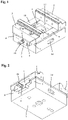
- the centric clamping device shown in different views contains a base body 1 on which two clamping jaws 2 and 3 are slidably guided via slides 4 and 5 and can be adjusted in opposite directions by an adjusting mechanism with an adjusting spindle 6 .
- the base body 1 has two spaced side walls 7 and 8 with upper guide surfaces 9 and 10 .
- the two guide surfaces 9 and 10 are formed on a hardened and ground upper part of the two side walls 7 and 8 of the base body 1 .
- the guide surfaces 9 and 10 can also be arranged on separate guide rails or guide rails that can be replaced if necessary.
- the two slides 4 and 5 are fitted between the two side panels 7 and 8 of the base body 1 and are guided in a displaceable manner.
- the slides 4 and 5 have a stepped cross section with an upper bearing surface 11 .
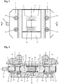
- FIG. 4 As can be seen, in the upper bearing surface 11 of the two slides 4 and 5, two indentations 12 and 13 are arranged one behind the other, viewed in the longitudinal direction of the base body 1, for the form-fitting engagement of a projection 14 projecting downwards from the underside of the clamping jaws 2 and 3.
- the clamping jaws 2 and 3 can be offset inwards or outwards and figure 3 recognizable screws 15 are fastened to the respective slide 4 or 5 in the exact position.
- the clamping jaws 2 and 3 can have any shape adapted to the respective clamping task.
- the clamping jaws 2 and 3 are designed as reversible jaws with different clamping surfaces. By turning the clamping jaws 2 and 3, the clamping range can be expanded or changed in a simple manner.
- the adjusting spindle 6 In the middle of the base body 1, between the two side walls 7 and 8, there is a bearing block 16, which is closed at the top and to the side, for mounting the adjusting spindle 6.
- the two slides 4 and 5 have a recess 17 or a cover for receiving the bearing block 16 and for covering the adjusting spindle 6 on the end faces facing one another.
- the adjustment spindle 6 is covered by the recesses 17 or the covers on the slides 4 and 5 and the chips are deflected.
- the adjusting spindle 6 is mounted rotatably about its longitudinal axis and secured in the axial direction by a spindle bearing 18, which will be explained in more detail below.
- the adjusting spindle 6 mounted centrally within the bearing block 16 has an adjusting pin 19 which protrudes outwards from the base body 1 and the slide 5 and is provided here with an external hexagon, as well as two external threads 20 and 21 designed as right-hand and left-hand threads for engagement with corresponding internal threads 22 and 23 on through holes 24 and 25 of the two slides 4 and 5 contains.
- the two slides 4 and 5 can be moved in opposite directions to one another and the clamping jaws 2 and 3 can thus be moved together or apart at the same time.
- the two slides 4 and 5 are sealed off from the adjusting spindle 6 at their mutually facing end faces via annular sealing elements 26 .
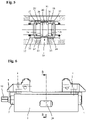
- the bearing block 16 shown in detail is designed in one piece with the base body 1 in the embodiment shown and contains a through opening 27 running in the longitudinal direction of the base body 1, in which the spindle bearing 18 for the adjusting spindle 6 is accommodated.
- the spindle bearing 18 comprises two bearing sleeves 28 and 29 which are arranged axially adjustable within the through-opening 27 and in which the adjusting spindle 6 is rotatably mounted.
- the adjusting spindle 6 contains a central annular collar 30 and two annular grooves 31 and 32 provided on the right and left of the annular collar 30, in which rolling elements 33 distributed over the circumference of the adjusting spindle 6 are mounted.
- the two bearing sleeves 28 and 29 each have an external thread 34 for engaging in a corresponding internal thread 35 of the through opening 27 and each contain a shoulder-shaped bearing surface 36 on the end faces facing one another, on which the inner side guided in the two annular grooves 31 and 32 and here as Balls formed rolling elements 33 come to rest on the outside.
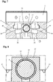
- the central bearing block 16 arranged between the two side walls of the base body 1 is shown in a cross section. Between the bearing block 16 and the two side walls 7 and 8 of the base body 1 are depressions 37 with countersunk holes 38 for fastening the base body 1 to a machine table or the like. Provided. In the two side panels 7 and 8, passages 39 leading outwards from the recesses 37 are arranged with bottom surfaces 40 leading obliquely downwards. As a result, chips that get into the depressions 37 can be discharged to the outside in a simple and effective manner.
- the adjusting spindle 6 and also the bearing block 16 are covered by the recesses 17 or the covers on the slides 4 and 5 and the chips are guided to the depressions 37 and from there via the passages 39 to the outside.
- the two clamping jaws 2 and 3 are designed as reversible jaws and have straight clamping surfaces on one side and stepped clamping surfaces on the other side. By turning the clamping jaws 2 and 3, the clamping range can easily be expanded.
- the clamping jaws 2 and 3 can also have any other shape that is adapted to the respective clamping task.
Landscapes
- Engineering & Computer Science (AREA)
- Mechanical Engineering (AREA)
- Jigs For Machine Tools (AREA)
- Machine Tool Units (AREA)
- Clamps And Clips (AREA)
Description
- Die Erfindung betrifft eine Zentrisch-Spannvorrichtung nach dem Oberbegriff des Patentanspruchs 1.
- Zentrisch-Spannvorrichtungen weisen üblicherweise einen z.B. auf einem Maschinentisch aufspannbaren Grundkörper, zwei an dem Grundkörper über Längsführungen verschiebbar geführte Spannbacken und eine Verstellspindel zur gegenläufigen Verstellung der beiden Spannbacken auf. Mit Hilfe der Verstellspindel können die am Grundkörper verschiebbar angeordneten Spannbacken gleichzeitig auseinander- und zusammengefahren werden, wodurch eine zentrische Spannung von Werkstücken ermöglicht wird.
- Aus der
DE 10 2012 112 755 A1 ist eine gattungsgemäße Zentrisch-Spannvorrichtung bekannt. Diese weist einen Grundkörper, zwei am Grundkörper verschiebbar geführte Spannbacken und eine mittels einer Spindellagerung drehbar am Grundkörper gelagerte Verstellspindel zur gegenläufigen Verstellung der beiden Spannbacken auf. Die Spindelllagerung besteht bei dieser bekannten Spannvorrichtung aus einem mittels Schrauben am Grundkörper befestigten Lagerstück, das einen schalenförmigen Lagersteg zum Eingriff in eine Ringnut der Verstellspindel enthält. - In der
DE 20 2004 009 517 U1 ist eine Spanneinrichtung mit einem Grundkörper und zwei Spannbacken offenbart, die einander gegenüberliegend an dem Grundkörper angeordnet und entlang einer gemeinsamen Achse aufeinander zu und voneinander weg verstellbar geführt sind. Die Verstellung der Spannbacken erfolgt über eine Stellspindel, die in einem zentralen Lagergehäuse drehbar gelagert ist und an ihren Endbereichen Außengewindeabschnitte gegensätzlicher Steigung aufweist, welche in die Spannbacken eingeschraubt sind. - Die
DE 10 2013 104 467 A1 offenbart einen Zentrischspanner, bei dem an einem Grundkörper zwei gegeneinander verstellbare Spannbacken verschiebbar geführt sind. Die Spannbacken sind über eine in einem mittigen Lagerblock drehbar gelagerte Gewindespindel verstellbar. - Die
DE 297 23 435 U1 offenbart eine Zentrisch-Spannvorrichtung mit zwei linear geführt gegeneinander bewegbaren Spannschlitten. Die Verstellung der Spannschlitten erfolgt durch eine innerhalb eines Lagerblocks drehbar gelagerte Gewindespindel, die an ihren beiden Enden gegenläufige Gewindeabschnitte zum Eingriff in Gewindemuttern zweier Kolben aufweist. - Aus der
EP 1 688 219 A1 ist eine Spanneinrichtung mit einer an einem Grundkörper fest angeordneten ersten Spannbacke und einer am Grundkörpers verstellbar geführten zweiten Spannbacke bekannt. Die zweite Spannbacke ist mittels einer in einer Spindelausnehmung des Grundkörpers angeordneten Schraubspindel verstellbar. Zur Vermeidung von Verschmutzungen ist die Spindelausnehmung des Grundkörpers zwischen den beiden Spannbacken über den gesamten Verstellbereich der Spannbacken durch ein Deckelement abgedeckt. - Die
DE 10 2007 027 808 B3 betrifft eine Spannvorrichtung, bei der die Träger der Spannbacken als die Verstellspindel umschließende Halbschalen ausgebildet sind. - Aufgabe der Erfindung ist es, eine Zentrisch-Spannvorrichtung der eingangs genannten Art zu schaffen, die eine gegen Verschmutzung optimal geschützte Spindelllagerung mit hoher Genauigkeit enthält.
- Diese Aufgabe wird durch eine Zentrisch-Spannvorrichtung mit den Merkmalen des Anspruchs 1 gelöst. Zweckmäßige Weiterbildungen und vorteilhafte Ausführungsformen der Erfindung sind Gegenstand der Unteransprüche.
- Bei der erfindungsgemäßen Zentrisch-Spannvorrichtung ist die Spindellagerung in einem Lagerblock untergebracht und weist zwei innerhalb des Lagerblocks axial verstellbare Lagerhülsen auf. Durch die axiale Verstellung der beiden Lagerhülsen kann nicht nur axiale Lage der Verstellspindel bezüglich des Grundkörpers eingestellt werden, über eine gegenseitige Verstellung der beiden Lagerhülsen kann die Spindellagerung außerdem vorgespannt und spielfrei eingestellt werden. Dadurch ist eine hohe Präzision und gute Wiederholgenauigkeit erreichbar. Außerdem ist die Verstellspindel über den Lagerblock im Bereich der Lagerung komplett abgedeckt und abgedichtet. Die Zentrisch-Spannvorrichtung ist somit unempfindlich gegen Späne und die Verstellspindel ist in einem geschlossenen System vor Verschmutzungen geschützt.
- In einer besonders reibungsarmen und positionsgenau einstellbaren Ausführung kann die Spindellagerung als Rollenlagerung mit mehreren zwischen den Lagerhülsen und der Verstellspindel geführten Wälzkörpern ausgebildet sein. Die Verstellspindel kann hierzu z.B. zwei voneinander beabstandete Ringnuten zur innenseitigen Lagerung der z.B. als Kugeln ausgebildeten Wälzköper aufweisen. Die beiden Lagerhülsen können an den einander zugewandten Stirnseiten jeweils eine schulterförmige Lagerfläche zur außenseitigen Lagerung der Wälzköper enthalten. Durch gegenseitiges Verspannen der beiden Lagerhülsen, können die schulterförmigen Lagerflächen zur Anlage an den Kugeln gebracht und somit eine möglichst spielfreie Einstellung erreicht werden. Die Spindellagerung könnte aber auch als Gleitlagerung mit axial verstellbaren Gleitlagerhülsen ausgebildet sein.
- Eine einfache axiale Verstellung der Lagerhülsen kann dadurch erreicht werden, dass die beiden Lagerhülsen jeweils ein Außengewinde zum Eingriff in ein entsprechendes Innengewinde einer durch den Lagerblock verlaufenden Durchgangsöffnung aufweisen.
- In einer besonders stabilen und vor Verschmutzung optimal geschützten Bauweise kann der über den gesamten Umfang geschlossene Lagerblock einteilig mit dem Grundkörper ausgebildet sein. Ein optimierter Späneabfluss ist dadurch erreichbar, dass von Vertiefungen zwischen dem Lagerblock und zwei Seitenwangen des Grundkörpers nach außen führende Durchgänge mit schräg nach unten führenden Bodenflächen angeordnet sind.
- Gemäß einer weiteren vorteilhaften Ausführung können die beiden Spannbacken über in dem Grundkörper verschiebbar geführte Schieber verstellbar sein. Die Schieber können so in den Grundkörper eingebaut sein, dass sich eine vor Verschmutzung geschützte und gegen Späne unempfindliche Bauweise ergibt. Die Verstellspindel weist zweckmäßigerweise zwei als Rechts- bzw. Linksgewinde ausgeführte Außengewinde zum Eingriff mit entsprechenden Innengewinden an Durchgangsbohrungen der beiden Schieber auf.
- Die Spannbacken sind vorzugsweise lösbar auf den Schiebern befestigt. Dadurch können die Spannbacken bei Bedarf ausgetauscht und an die jeweilige Spannaufgabe angepasst werden. Die Spannbacken können eine beliebige Form aufweisen.
- Weitere Besonderheiten und Vorzüge der Erfindung ergeben sich aus der folgenden Beschreibung eines bevorzugten Ausführungsbeispiels anhand der Zeichnung. Es zeigen:
- Figur 1
- eine erfindungsgemäße Zentrisch-Spannvorrichtung in einer Perspektive von oben;
- Figur 2
- die Zentrisch-Spannvorrichtung von
Figur 1 in einer Perspektive von unten; - Figur 3
- die Zentrisch-Spannvorrichtung von
Figur 1 in einer Draufsicht; - Figur 4
- die Zentrisch-Spannvorrichtung von
Figur 1 in einem Längsschnitt entlang der Linie A-A vonFigur 3 ; - Figur 5
- eine vergrößerte Detailansicht des Bereichs C von
Figur 4 ; - Figur 6
- die Zentrisch-Spannvorrichtung von
Figur 1 in einer Seitenansicht; - Figur 7
- einen Querschnitt entlang der Linie B-B von
Figur 6 und - Figur 8
- eine vergrößerte Detailansicht des Bereichs D von
Figur 7 . - Die in den
Figuren 1 bis 4 in unterschiedlichen Ansichten dargestellte Zentrisch-Spannvorrichtung enthält einem Grundkörper 1, an dem zwei Spannbacken 2 und 3 über Schieber 4 und 5 verschiebbar geführt und durch einen Verstellmechanismus mit einer Verstellspindel 6 gegenläufig verstellbar sind. Der Grundkörper 1 weist zwei voneinander beabstandete Seitenwangen 7 und 8 mit oberen Führungsflächen 9 und 10 auf. Bei der gezeigten Ausführungsform sind die beiden Führungsflächen 9 und 10 an einem gehärteten und geschliffenen oberen Teil der beiden Seitenwangen 7 und 8 des Grundkörpers 1 ausgeführt. Die Führungsflächen 9 und 10 können aber auch an gesonderten und bei Bedarf auswechselbaren Führungsschienen oder Führungsleisten angeordnet sein. Zwischen den beiden Seitenwangen 7 und 8 des Grundkörpers 1 sind die beiden Schieber 4 und 5 eingepasst und verschiebbar geführt. Bei dem gezeigten Ausführungsbeispiel weisen die Schieber 4 und 5 einen stufenförmigen Querschnitt mit einer oberen Auflagefläche 11 auf. - Wie aus
Figur 4 hervorgeht, sind in der oberen Auflagefläche 11 der beiden Schieber 4 und 5 jeweils zwei in Längsrichtung des Grundkörpers 1 gesehen hintereinander liegende Vertiefungen 12 und 13 zum formschlüssigen Eingriff eines von der Unterseite der Spannbacken 2 und 3 nach unten vorstehenden Ansatzes 14 angeordnet. Dadurch können die Spannbacken 2 und 3 nach innen oder außen versetzt und durch inFigur 3 erkennbare Schrauben 15 an dem jeweiligen Schieber 4 bzw. 5 positionsgenau befestigt werden. Die Spannbacken 2 und 3 können eine beliebige, an die jeweilige Spannaufgabe angepasste Form aufweisen. Bei der gezeigten Ausführung sind die Spannbacken 2 und 3 als Wendebacken mit unterschiedlichem Spannflächen ausgeführt. Durch Umdrehen der Spannbacken 2 und 3 kann so der Spannbereich auf einfache Weise erweitert bzw. verändert werden. - In der Mitte des Grundkörpers 1 ist zwischen den beiden Seitenwangen 7 und 8 ein nach oben und zur Seite geschlossener Lagerblock 16 zur Lagerung der Verstellspindel 6 angeordnet. Die beiden Schieber 4 und 5 weisen an den einander zugewandeten Stirnseiten eine Ausnehmung 17 oder eine Abdeckung zur Aufnahme des Lagerblocks 16 und zur Abdeckung der Verstellspindel 6 auf. Dadurch können die beiden Schieber 4 und 5 unter Abdeckung der Verstellspindel 6 über dem Lagerblock 16 zusammengeschoben werden. Durch die Ausnehmungen 17 oder die Abdeckungen an den Schiebern 4 und 5 wird die Verstellspindel 6 abgedeckt und die Späne werden abgelenkt. Innerhalb des Lagerblocks 16 ist die Verstellspindel 6 durch eine im Folgenden noch näher erläuterte Spindellagerung 18 um ihre Längsachse drehbar und in Axialrichtung gesichert gelagert.
- Aus
Figur 4 ist ersichtlich, dass die innerhalb des Lagerblocks 16 mittig gelagerte Verstellspindel 6 einen gegenüber dem Grundköper 1 und dem Schieber 5 nach außen vorstehenden und hier mit einem Außensechskant versehenen Stellzapfen 19 sowie zwei als Rechts- bzw. Linksgewinde ausgeführte Außengewinde 20 bzw. 21 zum Eingriff mit entsprechenden Innengewinden 22 bzw. 23 an Durchgangsbohrungen 24 und 25 der beiden Schieber 4 und 5 enthält. Durch Drehung des Stellzapfens 19 mit Hilfe einer geeigneten Handkurbel oder eines anderen Betätigungselements können so die beiden Schieber 4 und 5 entgegengesetzt zueinander verschoben und die Spannbacken 2 und 3 somit gleichzeitig zusammen- bzw. auseinander gefahren werden. Über ringförmige Dichtelemente 26 sind die beiden Schieber 4 und 5 an ihren einander zugewandten Stirnseiten gegenüber der Verstellspindel 6 abgedichtet. - Der in
Figur 5 im Detail dargestellte Lagerblock 16 ist bei der gezeigten Ausführung einteilig mit dem Grundkörper 1 ausgeführt und enthält eine in Längsrichtung des Grundkörpers 1 verlaufende Durchgangsöffnung 27, in der die Spindellagerung 18 für die Verstellspindel 6 untergebracht ist. Die Spindellagerung 18 umfasst zwei innerhalb der Durchgangsöffnung 27 axial verstellbar angeordnete Lagerhülsen 28 und 29, in denen die Verstellspindel 6 drehbar gelagert ist. Die Verstellspindel 6 enthält einen zentralen Ringbund 30 und zwei rechts und links vom Ringbund 30 vorgesehene Ringnuten 31 bzw. 32, in denen über den Umfang der Verstellspindel 6 verteilte Wälzkörper 33 gelagert sind. Die beiden Lagerhülsen 28 und 29 weisen jeweils ein Außengewinde 34 zum Eingriff in ein entsprechendes Innengewinde 35 der Durchgangsöffnung 27 auf und enthalten an den einander zugewandten Stirnseiten jeweils eine schulterförmige Lagerfläche 36, an der die innenseitig in den beiden Ringnuten 31 und 32 geführten und hier als Kugeln ausgebildeten Wälzkörper 33 außenseitig zur Anlage gelangen. Durch eine gleichgerichtete Verstellung der beiden Lagerhülsen 28 und 29 innerhalb des Lagerblocks 16 kann die Lage der Verstellspindel 6 bezüglich des Grundkörpers 1 eingestellt werden. Über einen gegenseitige Verstellung der beiden Lagerhülsen 28 und 29 kann die Spindellagerung 18 dagegen vorgespannt und spielfrei eingestellt werden. - In den
Figuren 7 und 8 ist der zwischen den beiden Seitenwangen des Grundkörpers 1 angeordnete zentrale Lagerblock 16 in einem Querschnitt gezeigt. Zwischen dem Lagerblock 16 und den beiden Seitenwangen 7 und 8 des Grundkörpers 1 sind Vertiefungen 37 mit Senkbohrungen 38 zur Befestigung des Grundkörpers 1 auf einem Maschinentisch oder dgl. vorgesehen. In den beiden Seitenwangen 7 und 8 sind von den Vertiefungen 37 nach außen führende Durchgänge 39 mit schräg nach unten führenden Bodenflächen 40 angeordnet. Dadurch können in die Vertiefungen 37 gelangende Späne auf einfache und effektive Weise nach außen abgeführt werden. Durch die Ausnehmungen 17 oder die Abdeckungen an den Schiebern 4 und 5 wird die Verstellspindel 6 und auch der Lagerblock 16 abgedeckt und die Späne werden zu den Vertiefungen 37 und von dort über die Durchgänge 39 nach außen gelenkt. - Bei der gezeigten Ausführung sind die beiden Spannbacken 2 und 3 als Wendebacken ausgebildet und weisen an der einen Seite gerade und an der anderen Seite treppenförmige Spannflächen auf. Durch Umdrehen der Spannbacken 2 und 3 kann so der Spannbereich auf einfache Weise erweitert werden. Die Spannbacken 2 und 3 können aber auch jede andere beliebige, an die jeweilige Spannaufgabe angepasste, Form aufweisen.
Claims (11)
- Zentrisch-Spannvorrichtung, die einen Grundkörper (1), zwei am Grundkörper (1) verschiebbar geführte Spannbacken (2, 3) und eine mittels einer Spindellagerung (18) drehbar am Grundkörper (1) gelagerte Verstellspindel (6) zur gegenläufigen Verstellung der beiden Spannbacken (2, 3) enthält, wobei die Spindellagerung (18) in einem Lagerblock (16) untergebracht ist und zwei innerhalb des Lagerblocks (16) axial verstellbare Lagerhülsen (28, 29) enthält und wobei die beiden Spannbacken (2, 3) über in dem Grundkörper (1) verschiebbar geführte Schieber (4, 5) verstellbar sind, dadurch gekennzeichnet, dass die beiden Schieber (4, 5) an den einander zugewandten Stirnseiten eine Ausnehmung (17) zur Aufnahme des Lagerblocks (16) und zur Abdeckung der Verstellspindel (6) aufweisen.
- Zentrisch-Spannvorrichtung nach Anspruch 1, dadurch gekennzeichnet, dass die Spindellagerung (18) als Rollenlagerung mit mehreren zwischen den Lagerhülsen (28, 29) und der Verstellspindel (6) angeordneten Wälzkörpern (33) ausgebildet ist.
- Zentrisch-Spannvorrichtung nach Anspruch 2, dadurch gekennzeichnet, dass die Verstellspindel (6) zwei voneinander beabstandete Ringnuten (31, 33) zur innenseitigen Lagerung der Wälzköper (33) enthält.
- Zentrisch-Spannvorrichtung nach Anspruch 2 oder 3, dadurch gekennzeichnet, dass die beiden Lagerhülsen (28, 29) an den einander zugewandten Stirnseiten jeweils eine schulterförmige Lagerfläche (36) zur außenseitigen Lagerung der Wälzköper (33) aufweisen.
- Zentrisch-Spannvorrichtung nach einem der Ansprüche 1 bis 4, dadurch gekennzeichnet, dass die beiden Lagerhülsen (28, 29) jeweils ein Außengewinde (34) zum Eingriff in ein entsprechendes Innengwinde (35) einer durch den Lagerblock (16) verlaufenden Durchgangsöffnung (27) aufweisen.
- Zentrisch-Spannvorrichtung nach einem der Ansprüche 1 bis 5, dadurch gekennzeichnet, dass der Lagerblock (16) einteilig mit dem Grundkörper (1) ausgebildet ist.
- Zentrisch-Spannvonichtung nach Anspruch 6, dadurch gekennzeichnet, dass die Verstellspindel (6) zwei als Rechts- bzw. Linksgewinde ausgeführte Außengewinde (20, 21) zum Eingriff mit entsprechenden Innengewinden (22, 23) an Durchgangsbohrungen (24, 25) der beiden Schieber (4, 5) enthält.
- Zentrisch-Spannvorrichtung nach Anspruch 6 oder 7, dadurch gekennzeichnet, dass die beiden Spannbacken (2, 3) lösbar an den Schiebern (4, 5) befestigt sind.
- Zentrisch-Spannvorrichtung nach einem der Ansprüche 1 bis 8, dadurch gekennzeichnet, dass der Lagerblock (16) zwischen zwei Seitenwangen (7, 8) des Grundkörpers (1) angeordnet ist.
- Zentrisch-Spannvorrichtung nach Anspruch 9, dadurch gekennzeichnet, dass zwischen dem Lagerblock (16) und den beiden Seitenwangen (7, 8) Vertiefungen (37) angeordnet ist.
- Zentrisch-Spannvorrichtung nach Anspruch 10, dadurch gekennzeichnet, dass in den beiden Seitenwangen (7, 8) von den Vertiefungen (37) nach außen führende Durchgänge (39) mit schräg nach unten führenden Bodenflächen (40) angeordnet sind.
Applications Claiming Priority (1)
| Application Number | Priority Date | Filing Date | Title |
|---|---|---|---|
| DE102014110352.1A DE102014110352B3 (de) | 2014-07-23 | 2014-07-23 | Zentrisch-Spannvorrichtung |
Publications (3)
| Publication Number | Publication Date |
|---|---|
| EP2977145A1 EP2977145A1 (de) | 2016-01-27 |
| EP2977145B1 EP2977145B1 (de) | 2017-05-10 |
| EP2977145B2 true EP2977145B2 (de) | 2022-10-26 |
Family
ID=53785410
Family Applications (1)
| Application Number | Title | Priority Date | Filing Date |
|---|---|---|---|
| EP15174952.0A Active EP2977145B2 (de) | 2014-07-23 | 2015-07-02 | Zentrisch-spannvorrichtung |
Country Status (3)
| Country | Link |
|---|---|
| US (1) | US9962812B2 (de) |
| EP (1) | EP2977145B2 (de) |
| DE (1) | DE102014110352B3 (de) |
Families Citing this family (13)
| Publication number | Priority date | Publication date | Assignee | Title |
|---|---|---|---|---|
| US11666997B1 (en) * | 2015-11-18 | 2023-06-06 | Elijah Tooling, Inc. | Precision locating fastening device |
| CZ308696B6 (cs) * | 2016-02-24 | 2021-03-03 | Protechnik S.R.O. | Strojní svěrák s modulárním systémem upínání |
| JP6674805B2 (ja) * | 2016-03-16 | 2020-04-01 | 株式会社ナベヤ | センタリング調整機能付きマシンバイス |
| DE102016117420B3 (de) | 2016-09-15 | 2018-03-01 | Allmatic-Jakob Spannsysteme Gmbh | Spannantrieb und Zentrischspannsystem |
| CN106737302B (zh) * | 2017-01-22 | 2019-08-27 | 高密宏泰机床制造有限公司 | 浮动式夹具 |
| ES2698703A1 (es) * | 2017-08-04 | 2019-02-05 | Fresmak Sa | Dispositivo de sujeción de piezas |
| DE102017122112B4 (de) * | 2017-09-25 | 2021-12-09 | Lang Technik Gmbh | Schraubstockvorrichtung |
| ES2923395T3 (es) * | 2019-01-28 | 2022-09-27 | Oml Srl | Dispositivo de sujeción, en particular un tornillo de banco |
| US11667012B1 (en) * | 2019-03-21 | 2023-06-06 | Kurt Manufacturing Company, Inc. | Self-centering dual direction clamping vise with adjustable center support |
| DE102020101064B3 (de) | 2020-01-17 | 2021-03-18 | Lang Technik Gmbh | Werkstückspannvorrichtung |
| DE102021117229B4 (de) * | 2021-07-05 | 2024-12-05 | Lang Technik Gmbh | Spannvorrichtung und Verfahren zur Handhabung eines Werkstücks |
| TWI785835B (zh) * | 2021-10-07 | 2022-12-01 | 林長毅 | 中心虎鉗 |
| WO2023247057A1 (de) * | 2022-06-24 | 2023-12-28 | Hemo Ag | Zentrumspannvorrichtung zum spannen von mechanisch zu bearbeitenden werkstücken |
Citations (1)
| Publication number | Priority date | Publication date | Assignee | Title |
|---|---|---|---|---|
| US20140131933A1 (en) † | 2012-11-15 | 2014-05-15 | Chris Taylor | Self-Centering Vise |
Family Cites Families (25)
| Publication number | Priority date | Publication date | Assignee | Title |
|---|---|---|---|---|
| US1811299A (en) * | 1928-08-25 | 1931-06-23 | Jr Paul Brockhaus | Vise |
| US3720116A (en) * | 1971-03-23 | 1973-03-13 | Bendix Corp | Arrangement for preloading ball screw assemblies & method of manufacture of the ball screw nut therefor |
| DE3026158A1 (de) | 1980-07-10 | 1982-02-04 | Victor Göteborg Crail | Vorrichtung zum schnellen verschieben und blockieren von einem oder mehreren beweglichen teilen |
| GB2088496B (en) * | 1980-11-29 | 1985-05-15 | Smith Bernard | Locking mechanism for screws and shafts |
| US4413818A (en) | 1981-08-24 | 1983-11-08 | Kurt Manufacturing Company, Inc. | Combination vise |
| US4591199A (en) * | 1984-05-24 | 1986-05-27 | Zaytran Inc. | Device for gripping workpieces |
| US4934674A (en) * | 1989-03-22 | 1990-06-19 | Kurt Manufacturing Company, Inc. | Two station, single action vise |
| DE3925718A1 (de) | 1989-08-03 | 1991-02-07 | Saurer Allma Gmbh | Schraubstock zum zentrischen spannen |
| US5501118A (en) * | 1994-12-05 | 1996-03-26 | Thomson Saginaw Ball Screw Co., Inc. | Ball nut and screw assembly with preload retaining ball return tube clamp |
| DE19717467C2 (de) * | 1996-04-26 | 1999-03-04 | Kohn Spannwerkzeuge Mechanisch | Spannstock |
| DE19621754C2 (de) | 1996-05-30 | 2000-10-12 | Konrad Kreuzer | Hochdruckspanner mit Kraftverstärker |
| DE29723435U1 (de) * | 1997-08-30 | 1998-08-27 | Hico Himmel & Co KG, 78727 Oberndorf | Vorrichtung zum zentrierten Spannen von Werkstücken o.dgl. |
| AT3049U1 (de) * | 1997-08-30 | 1999-09-27 | Hico Himmel & Co Kg | Vorrichtung zum zentrierten spannen von werkstücken oder dergleichen |
| US6017026A (en) * | 1997-12-11 | 2000-01-25 | Durfee, Jr.; David L. | Machining vise |
| US6079704A (en) * | 1998-09-08 | 2000-06-27 | Buck; James R. | Timing device for workholding apparatus |
| FR2792567B3 (fr) | 1999-04-22 | 2001-06-08 | Sagop | Etau de serrage |
| DE202004009517U1 (de) * | 2004-06-17 | 2004-10-14 | Schunk GmbH & Co. KG Fabrik für Spann- und Greiftechnik | Spanneinrichtung |
| DE102004040360A1 (de) | 2004-08-20 | 2006-02-23 | Ina-Schaeffler Kg | Kugelgewindetrieb |
| ATE345194T1 (de) * | 2005-06-15 | 2006-12-15 | Hb Feinmechanik Gmbh & Co Kg | Spanneinrichtung mit einem deckelement für ihre spindelausnehmung |
| DE102007027808B3 (de) | 2007-06-13 | 2008-08-14 | Gressel Ag | Spannvorrichtung |
| ES2336399B8 (es) | 2007-07-25 | 2011-08-02 | Fresmak, S.A. | Mordaza. |
| CH699112A2 (de) * | 2008-07-11 | 2010-01-15 | Dieter Mosig | Spannvorrichtung mit Mitteln zur Spülung. |
| US8256753B2 (en) * | 2009-06-17 | 2012-09-04 | Productivity Systems, Llc | High-density fixture vise |
| CH707170B1 (de) * | 2012-11-09 | 2016-03-31 | Raphael Rogenmoser | Vorrichtung zum zentrierten Spannen eines Gegenstands. |
| DE102012112755B4 (de) * | 2012-12-20 | 2014-11-20 | Gressel Ag | Zentrisch-Spannvorrichtung |
-
2014
- 2014-07-23 DE DE102014110352.1A patent/DE102014110352B3/de active Active
-
2015
- 2015-07-02 EP EP15174952.0A patent/EP2977145B2/de active Active
- 2015-07-21 US US14/805,020 patent/US9962812B2/en active Active
Patent Citations (1)
| Publication number | Priority date | Publication date | Assignee | Title |
|---|---|---|---|---|
| US20140131933A1 (en) † | 2012-11-15 | 2014-05-15 | Chris Taylor | Self-Centering Vise |
Also Published As
| Publication number | Publication date |
|---|---|
| EP2977145A1 (de) | 2016-01-27 |
| DE102014110352B3 (de) | 2015-10-08 |
| US20160023329A1 (en) | 2016-01-28 |
| EP2977145B1 (de) | 2017-05-10 |
| US9962812B2 (en) | 2018-05-08 |
Similar Documents
| Publication | Publication Date | Title |
|---|---|---|
| EP2977145B2 (de) | Zentrisch-spannvorrichtung | |
| EP1946890B1 (de) | Zentrierspanner | |
| DE102007004057B3 (de) | Zentrierspanner | |
| EP3028812A1 (de) | Spannvorrichtung | |
| DE3718157A1 (de) | Schraubstock | |
| EP3685963B1 (de) | Spannvorrichtung, insbesondere schraubstock | |
| DE102014007055A1 (de) | Vorrichtung zum Festspannen eines Gegenstandes | |
| EP0901883B1 (de) | Spannvorrichtung, insbesondere Maschinenschraubstock | |
| DE4300344A1 (de) | ||
| DE19810771C1 (de) | Basis-Profil für die Spanntechnik zu vermessender Werkstücke | |
| DE1453213C3 (de) | ||
| EP0997655B1 (de) | Linearführung | |
| DE3925642A1 (de) | Werkzeugmaschine | |
| DE3841480C2 (de) | ||
| DE4317049A1 (de) | Linearführung mit klemmbarem Führungselement | |
| DE2705628C2 (de) | Aufbau-Werkzeugmaschine | |
| DE20009521U1 (de) | Niederzug-Schnellspannvorrichtung | |
| EP1245358A1 (de) | Anschlagvorrichtung für eine Zugsäge, insbesondere eine Unterflurzugsäge | |
| DE102015014664B3 (de) | Aufnahmevorrichtung für eine mittig gelagerte Gewindespindel mit einem diese umfassenden Bund im Grundkörper eines Zentrierspanners | |
| EP3159100B1 (de) | Drehmaschine | |
| DE4012468C2 (de) | ||
| EP1213095A2 (de) | Spannwerkzeug | |
| DE19941234A1 (de) | Vorrichtung zum Einspannen von Werkstücken | |
| EP2803446B1 (de) | Spannvorrichtung | |
| DE3333624C2 (de) |
Legal Events
| Date | Code | Title | Description |
|---|---|---|---|
| PUAI | Public reference made under article 153(3) epc to a published international application that has entered the european phase |
Free format text: ORIGINAL CODE: 0009012 |
|
| AK | Designated contracting states |
Kind code of ref document: A1 Designated state(s): AL AT BE BG CH CY CZ DE DK EE ES FI FR GB GR HR HU IE IS IT LI LT LU LV MC MK MT NL NO PL PT RO RS SE SI SK SM TR |
|
| AX | Request for extension of the european patent |
Extension state: BA ME |
|
| 17P | Request for examination filed |
Effective date: 20160727 |
|
| RBV | Designated contracting states (corrected) |
Designated state(s): AL AT BE BG CH CY CZ DE DK EE ES FI FR GB GR HR HU IE IS IT LI LT LU LV MC MK MT NL NO PL PT RO RS SE SI SK SM TR |
|
| GRAP | Despatch of communication of intention to grant a patent |
Free format text: ORIGINAL CODE: EPIDOSNIGR1 |
|
| STAA | Information on the status of an ep patent application or granted ep patent |
Free format text: STATUS: GRANT OF PATENT IS INTENDED |
|
| INTG | Intention to grant announced |
Effective date: 20170110 |
|
| GRAS | Grant fee paid |
Free format text: ORIGINAL CODE: EPIDOSNIGR3 |
|
| GRAA | (expected) grant |
Free format text: ORIGINAL CODE: 0009210 |
|
| STAA | Information on the status of an ep patent application or granted ep patent |
Free format text: STATUS: THE PATENT HAS BEEN GRANTED |
|
| AK | Designated contracting states |
Kind code of ref document: B1 Designated state(s): AL AT BE BG CH CY CZ DE DK EE ES FI FR GB GR HR HU IE IS IT LI LT LU LV MC MK MT NL NO PL PT RO RS SE SI SK SM TR |
|
| REG | Reference to a national code |
Ref country code: GB Ref legal event code: FG4D Free format text: NOT ENGLISH |
|
| REG | Reference to a national code |
Ref country code: AT Ref legal event code: REF Ref document number: 891799 Country of ref document: AT Kind code of ref document: T Effective date: 20170515 Ref country code: CH Ref legal event code: NV Representative=s name: LUCHS AND PARTNER PATENTANWAELTE, CH Ref country code: CH Ref legal event code: EP |
|
| REG | Reference to a national code |
Ref country code: IE Ref legal event code: FG4D Free format text: LANGUAGE OF EP DOCUMENT: GERMAN |
|
| REG | Reference to a national code |
Ref country code: DE Ref legal event code: R096 Ref document number: 502015001025 Country of ref document: DE |
|
| REG | Reference to a national code |
Ref country code: FR Ref legal event code: PLFP Year of fee payment: 3 |
|
| REG | Reference to a national code |
Ref country code: NL Ref legal event code: FP |
|
| REG | Reference to a national code |
Ref country code: LT Ref legal event code: MG4D |
|
| PG25 | Lapsed in a contracting state [announced via postgrant information from national office to epo] |
Ref country code: ES Free format text: LAPSE BECAUSE OF FAILURE TO SUBMIT A TRANSLATION OF THE DESCRIPTION OR TO PAY THE FEE WITHIN THE PRESCRIBED TIME-LIMIT Effective date: 20170510 Ref country code: NO Free format text: LAPSE BECAUSE OF FAILURE TO SUBMIT A TRANSLATION OF THE DESCRIPTION OR TO PAY THE FEE WITHIN THE PRESCRIBED TIME-LIMIT Effective date: 20170810 Ref country code: GR Free format text: LAPSE BECAUSE OF FAILURE TO SUBMIT A TRANSLATION OF THE DESCRIPTION OR TO PAY THE FEE WITHIN THE PRESCRIBED TIME-LIMIT Effective date: 20170811 Ref country code: LT Free format text: LAPSE BECAUSE OF FAILURE TO SUBMIT A TRANSLATION OF THE DESCRIPTION OR TO PAY THE FEE WITHIN THE PRESCRIBED TIME-LIMIT Effective date: 20170510 Ref country code: FI Free format text: LAPSE BECAUSE OF FAILURE TO SUBMIT A TRANSLATION OF THE DESCRIPTION OR TO PAY THE FEE WITHIN THE PRESCRIBED TIME-LIMIT Effective date: 20170510 Ref country code: HR Free format text: LAPSE BECAUSE OF FAILURE TO SUBMIT A TRANSLATION OF THE DESCRIPTION OR TO PAY THE FEE WITHIN THE PRESCRIBED TIME-LIMIT Effective date: 20170510 |
|
| PG25 | Lapsed in a contracting state [announced via postgrant information from national office to epo] |
Ref country code: RS Free format text: LAPSE BECAUSE OF FAILURE TO SUBMIT A TRANSLATION OF THE DESCRIPTION OR TO PAY THE FEE WITHIN THE PRESCRIBED TIME-LIMIT Effective date: 20170510 Ref country code: BG Free format text: LAPSE BECAUSE OF FAILURE TO SUBMIT A TRANSLATION OF THE DESCRIPTION OR TO PAY THE FEE WITHIN THE PRESCRIBED TIME-LIMIT Effective date: 20170810 Ref country code: IS Free format text: LAPSE BECAUSE OF FAILURE TO SUBMIT A TRANSLATION OF THE DESCRIPTION OR TO PAY THE FEE WITHIN THE PRESCRIBED TIME-LIMIT Effective date: 20170910 Ref country code: PL Free format text: LAPSE BECAUSE OF FAILURE TO SUBMIT A TRANSLATION OF THE DESCRIPTION OR TO PAY THE FEE WITHIN THE PRESCRIBED TIME-LIMIT Effective date: 20170510 Ref country code: LV Free format text: LAPSE BECAUSE OF FAILURE TO SUBMIT A TRANSLATION OF THE DESCRIPTION OR TO PAY THE FEE WITHIN THE PRESCRIBED TIME-LIMIT Effective date: 20170510 Ref country code: SE Free format text: LAPSE BECAUSE OF FAILURE TO SUBMIT A TRANSLATION OF THE DESCRIPTION OR TO PAY THE FEE WITHIN THE PRESCRIBED TIME-LIMIT Effective date: 20170510 |
|
| PG25 | Lapsed in a contracting state [announced via postgrant information from national office to epo] |
Ref country code: SK Free format text: LAPSE BECAUSE OF FAILURE TO SUBMIT A TRANSLATION OF THE DESCRIPTION OR TO PAY THE FEE WITHIN THE PRESCRIBED TIME-LIMIT Effective date: 20170510 Ref country code: CZ Free format text: LAPSE BECAUSE OF FAILURE TO SUBMIT A TRANSLATION OF THE DESCRIPTION OR TO PAY THE FEE WITHIN THE PRESCRIBED TIME-LIMIT Effective date: 20170510 Ref country code: RO Free format text: LAPSE BECAUSE OF FAILURE TO SUBMIT A TRANSLATION OF THE DESCRIPTION OR TO PAY THE FEE WITHIN THE PRESCRIBED TIME-LIMIT Effective date: 20170510 Ref country code: DK Free format text: LAPSE BECAUSE OF FAILURE TO SUBMIT A TRANSLATION OF THE DESCRIPTION OR TO PAY THE FEE WITHIN THE PRESCRIBED TIME-LIMIT Effective date: 20170510 Ref country code: EE Free format text: LAPSE BECAUSE OF FAILURE TO SUBMIT A TRANSLATION OF THE DESCRIPTION OR TO PAY THE FEE WITHIN THE PRESCRIBED TIME-LIMIT Effective date: 20170510 |
|
| REG | Reference to a national code |
Ref country code: DE Ref legal event code: R026 Ref document number: 502015001025 Country of ref document: DE |
|
| PLBI | Opposition filed |
Free format text: ORIGINAL CODE: 0009260 |
|
| PLAX | Notice of opposition and request to file observation + time limit sent |
Free format text: ORIGINAL CODE: EPIDOSNOBS2 |
|
| PG25 | Lapsed in a contracting state [announced via postgrant information from national office to epo] |
Ref country code: SM Free format text: LAPSE BECAUSE OF FAILURE TO SUBMIT A TRANSLATION OF THE DESCRIPTION OR TO PAY THE FEE WITHIN THE PRESCRIBED TIME-LIMIT Effective date: 20170510 |
|
| 26 | Opposition filed |
Opponent name: ENGINEERING DATA Effective date: 20180212 |
|
| REG | Reference to a national code |
Ref country code: IE Ref legal event code: MM4A |
|
| PG25 | Lapsed in a contracting state [announced via postgrant information from national office to epo] |
Ref country code: IE Free format text: LAPSE BECAUSE OF NON-PAYMENT OF DUE FEES Effective date: 20170702 |
|
| REG | Reference to a national code |
Ref country code: BE Ref legal event code: MM Effective date: 20170731 |
|
| PG25 | Lapsed in a contracting state [announced via postgrant information from national office to epo] |
Ref country code: SI Free format text: LAPSE BECAUSE OF FAILURE TO SUBMIT A TRANSLATION OF THE DESCRIPTION OR TO PAY THE FEE WITHIN THE PRESCRIBED TIME-LIMIT Effective date: 20170510 |
|
| PLBB | Reply of patent proprietor to notice(s) of opposition received |
Free format text: ORIGINAL CODE: EPIDOSNOBS3 |
|
| PG25 | Lapsed in a contracting state [announced via postgrant information from national office to epo] |
Ref country code: LU Free format text: LAPSE BECAUSE OF NON-PAYMENT OF DUE FEES Effective date: 20170702 |
|
| REG | Reference to a national code |
Ref country code: FR Ref legal event code: PLFP Year of fee payment: 4 |
|
| PG25 | Lapsed in a contracting state [announced via postgrant information from national office to epo] |
Ref country code: BE Free format text: LAPSE BECAUSE OF NON-PAYMENT OF DUE FEES Effective date: 20170731 |
|
| PG25 | Lapsed in a contracting state [announced via postgrant information from national office to epo] |
Ref country code: MT Free format text: LAPSE BECAUSE OF FAILURE TO SUBMIT A TRANSLATION OF THE DESCRIPTION OR TO PAY THE FEE WITHIN THE PRESCRIBED TIME-LIMIT Effective date: 20170510 |
|
| PG25 | Lapsed in a contracting state [announced via postgrant information from national office to epo] |
Ref country code: HU Free format text: LAPSE BECAUSE OF FAILURE TO SUBMIT A TRANSLATION OF THE DESCRIPTION OR TO PAY THE FEE WITHIN THE PRESCRIBED TIME-LIMIT; INVALID AB INITIO Effective date: 20150702 Ref country code: MC Free format text: LAPSE BECAUSE OF FAILURE TO SUBMIT A TRANSLATION OF THE DESCRIPTION OR TO PAY THE FEE WITHIN THE PRESCRIBED TIME-LIMIT Effective date: 20170510 |
|
| PG25 | Lapsed in a contracting state [announced via postgrant information from national office to epo] |
Ref country code: CY Free format text: LAPSE BECAUSE OF FAILURE TO SUBMIT A TRANSLATION OF THE DESCRIPTION OR TO PAY THE FEE WITHIN THE PRESCRIBED TIME-LIMIT Effective date: 20170510 |
|
| PG25 | Lapsed in a contracting state [announced via postgrant information from national office to epo] |
Ref country code: MK Free format text: LAPSE BECAUSE OF FAILURE TO SUBMIT A TRANSLATION OF THE DESCRIPTION OR TO PAY THE FEE WITHIN THE PRESCRIBED TIME-LIMIT Effective date: 20170510 |
|
| APAH | Appeal reference modified |
Free format text: ORIGINAL CODE: EPIDOSCREFNO |
|
| APBM | Appeal reference recorded |
Free format text: ORIGINAL CODE: EPIDOSNREFNO |
|
| APBP | Date of receipt of notice of appeal recorded |
Free format text: ORIGINAL CODE: EPIDOSNNOA2O |
|
| APBQ | Date of receipt of statement of grounds of appeal recorded |
Free format text: ORIGINAL CODE: EPIDOSNNOA3O |
|
| PG25 | Lapsed in a contracting state [announced via postgrant information from national office to epo] |
Ref country code: TR Free format text: LAPSE BECAUSE OF FAILURE TO SUBMIT A TRANSLATION OF THE DESCRIPTION OR TO PAY THE FEE WITHIN THE PRESCRIBED TIME-LIMIT Effective date: 20170510 |
|
| PG25 | Lapsed in a contracting state [announced via postgrant information from national office to epo] |
Ref country code: PT Free format text: LAPSE BECAUSE OF FAILURE TO SUBMIT A TRANSLATION OF THE DESCRIPTION OR TO PAY THE FEE WITHIN THE PRESCRIBED TIME-LIMIT Effective date: 20170510 |
|
| PG25 | Lapsed in a contracting state [announced via postgrant information from national office to epo] |
Ref country code: AL Free format text: LAPSE BECAUSE OF FAILURE TO SUBMIT A TRANSLATION OF THE DESCRIPTION OR TO PAY THE FEE WITHIN THE PRESCRIBED TIME-LIMIT Effective date: 20170510 |
|
| REG | Reference to a national code |
Ref country code: AT Ref legal event code: MM01 Ref document number: 891799 Country of ref document: AT Kind code of ref document: T Effective date: 20200702 |
|
| PG25 | Lapsed in a contracting state [announced via postgrant information from national office to epo] |
Ref country code: AT Free format text: LAPSE BECAUSE OF NON-PAYMENT OF DUE FEES Effective date: 20200702 |
|
| APBU | Appeal procedure closed |
Free format text: ORIGINAL CODE: EPIDOSNNOA9O |
|
| PUAH | Patent maintained in amended form |
Free format text: ORIGINAL CODE: 0009272 |
|
| STAA | Information on the status of an ep patent application or granted ep patent |
Free format text: STATUS: PATENT MAINTAINED AS AMENDED |
|
| 27A | Patent maintained in amended form |
Effective date: 20221026 |
|
| AK | Designated contracting states |
Kind code of ref document: B2 Designated state(s): AL AT BE BG CH CY CZ DE DK EE ES FI FR GB GR HR HU IE IS IT LI LT LU LV MC MK MT NL NO PL PT RO RS SE SI SK SM TR |
|
| REG | Reference to a national code |
Ref country code: DE Ref legal event code: R102 Ref document number: 502015001025 Country of ref document: DE |
|
| REG | Reference to a national code |
Ref country code: NL Ref legal event code: FP |
|
| PGFP | Annual fee paid to national office [announced via postgrant information from national office to epo] |
Ref country code: NL Payment date: 20250723 Year of fee payment: 11 |
|
| PGFP | Annual fee paid to national office [announced via postgrant information from national office to epo] |
Ref country code: DE Payment date: 20250807 Year of fee payment: 11 |
|
| PGFP | Annual fee paid to national office [announced via postgrant information from national office to epo] |
Ref country code: IT Payment date: 20250731 Year of fee payment: 11 |
|
| PGFP | Annual fee paid to national office [announced via postgrant information from national office to epo] |
Ref country code: GB Payment date: 20250724 Year of fee payment: 11 |
|
| PGFP | Annual fee paid to national office [announced via postgrant information from national office to epo] |
Ref country code: FR Payment date: 20250723 Year of fee payment: 11 |
|
| PGFP | Annual fee paid to national office [announced via postgrant information from national office to epo] |
Ref country code: CH Payment date: 20250801 Year of fee payment: 11 |