EP2973500B1 - Motion platform configuration - Google Patents
Motion platform configuration Download PDFInfo
- Publication number
- EP2973500B1 EP2973500B1 EP14768483.1A EP14768483A EP2973500B1 EP 2973500 B1 EP2973500 B1 EP 2973500B1 EP 14768483 A EP14768483 A EP 14768483A EP 2973500 B1 EP2973500 B1 EP 2973500B1
- Authority
- EP
- European Patent Office
- Prior art keywords
- transducers
- motion platform
- active devices
- joint
- passive
- Prior art date
- Legal status (The legal status is an assumption and is not a legal conclusion. Google has not performed a legal analysis and makes no representation as to the accuracy of the status listed.)
- Active
Links
Images


Classifications
-
- F—MECHANICAL ENGINEERING; LIGHTING; HEATING; WEAPONS; BLASTING
- F16—ENGINEERING ELEMENTS AND UNITS; GENERAL MEASURES FOR PRODUCING AND MAINTAINING EFFECTIVE FUNCTIONING OF MACHINES OR INSTALLATIONS; THERMAL INSULATION IN GENERAL
- F16M—FRAMES, CASINGS OR BEDS OF ENGINES, MACHINES OR APPARATUS, NOT SPECIFIC TO ENGINES, MACHINES OR APPARATUS PROVIDED FOR ELSEWHERE; STANDS; SUPPORTS
- F16M11/00—Stands or trestles as supports for apparatus or articles placed thereon ; Stands for scientific apparatus such as gravitational force meters
- F16M11/02—Heads
- F16M11/18—Heads with mechanism for moving the apparatus relatively to the stand
-
- A—HUMAN NECESSITIES
- A63—SPORTS; GAMES; AMUSEMENTS
- A63G—MERRY-GO-ROUNDS; SWINGS; ROCKING-HORSES; CHUTES; SWITCHBACKS; SIMILAR DEVICES FOR PUBLIC AMUSEMENT
- A63G31/00—Amusement arrangements
- A63G31/02—Amusement arrangements with moving substructures
- A63G31/04—Amusement arrangements with moving substructures with jolting substructures
-
- A—HUMAN NECESSITIES
- A63—SPORTS; GAMES; AMUSEMENTS
- A63G—MERRY-GO-ROUNDS; SWINGS; ROCKING-HORSES; CHUTES; SWITCHBACKS; SIMILAR DEVICES FOR PUBLIC AMUSEMENT
- A63G31/00—Amusement arrangements
- A63G31/16—Amusement arrangements creating illusions of travel
-
- F—MECHANICAL ENGINEERING; LIGHTING; HEATING; WEAPONS; BLASTING
- F16—ENGINEERING ELEMENTS AND UNITS; GENERAL MEASURES FOR PRODUCING AND MAINTAINING EFFECTIVE FUNCTIONING OF MACHINES OR INSTALLATIONS; THERMAL INSULATION IN GENERAL
- F16M—FRAMES, CASINGS OR BEDS OF ENGINES, MACHINES OR APPARATUS, NOT SPECIFIC TO ENGINES, MACHINES OR APPARATUS PROVIDED FOR ELSEWHERE; STANDS; SUPPORTS
- F16M11/00—Stands or trestles as supports for apparatus or articles placed thereon ; Stands for scientific apparatus such as gravitational force meters
- F16M11/02—Heads
- F16M11/04—Means for attachment of apparatus; Means allowing adjustment of the apparatus relatively to the stand
- F16M11/043—Allowing translations
-
- F—MECHANICAL ENGINEERING; LIGHTING; HEATING; WEAPONS; BLASTING
- F16—ENGINEERING ELEMENTS AND UNITS; GENERAL MEASURES FOR PRODUCING AND MAINTAINING EFFECTIVE FUNCTIONING OF MACHINES OR INSTALLATIONS; THERMAL INSULATION IN GENERAL
- F16M—FRAMES, CASINGS OR BEDS OF ENGINES, MACHINES OR APPARATUS, NOT SPECIFIC TO ENGINES, MACHINES OR APPARATUS PROVIDED FOR ELSEWHERE; STANDS; SUPPORTS
- F16M11/00—Stands or trestles as supports for apparatus or articles placed thereon ; Stands for scientific apparatus such as gravitational force meters
- F16M11/02—Heads
- F16M11/04—Means for attachment of apparatus; Means allowing adjustment of the apparatus relatively to the stand
- F16M11/06—Means for attachment of apparatus; Means allowing adjustment of the apparatus relatively to the stand allowing pivoting
- F16M11/12—Means for attachment of apparatus; Means allowing adjustment of the apparatus relatively to the stand allowing pivoting in more than one direction
Definitions
- the present invention relates motion platforms that employ active devices, e.g., linear actuators, for inducing platform motion. More particularly, the present invention relates to the use of transducers (e.g., passive transducers) for the purpose of controlling the orientation and/or position of the motion platform and for the purpose of preventing the active devices from extending or retracting beyond their operational limits and, in turn protecting the motion platform and any load being carried by the motion platform.
- active devices e.g., linear actuators
- Motion platforms are used in a wide variety of applications.
- motion platforms may be used in vehicle simulators (e.g., aircraft simulators) for training purposes as well as recreational purposes.
- vehicle simulators e.g., aircraft simulators
- a motion platform may be moved about its one or more axes by operation of one or more actuators positioned beneath the motion platform, as illustrated in figure 1 of the publication.
- transducers may be employed for determining the position of or the orientation of the motion platform.
- Each transducer in US Patent Publication 2006/0222539 is positioned "immediately adjacent to an actuator."
- a microprocessor then receives and decodes signals from the transducers and, based thereon, calculates the position or the orientation of the motion platform. The calculations can then be used to feedback control signals to the actuators to further control and/or correct the position or orientation of the motion platform.
- Each transducer also may be employed to provide end of travel (EOT) protection for the corresponding actuator. As such, each transducer would more specifically provide discrete position sensing for the corresponding actuator in order to determine the degree to which the actuator is extended or retracted and prevent the actuator from operating outside its intended range.
- EOT end of travel
- the microprocessor In high speed applications particularly, the microprocessor must receive the output signals from the transducers and make the aforementioned calculations quickly and accurately. This ability is, at least in part, dependent on the complexity of the calculations. In US Patent Publication 2006/0222539 , the calculations may be quite complex because the output signal from each transducer is not continuously proportional to the state of the corresponding actuator and, in addition, the output of each actuator will influence the output signal of both transducers due to cross-coupling effects. The microprocessor must then solve for this lack of proportionality and the cross-coupling effects, which may result in a time consuming and complicated computational process.
- Vehicle simulators are but one example.
- amusement rides such as dark ride vehicles, which are in use at many amusement and/or theme parks around the world.
- dark ride vehicles are described and claimed, for example, in U.S. Patent No. 7,094,157 , entitled AMUSEMENT RIDE VEHICLE WITH PNEUMATICALLY ACTUATED CABIN AND MOTION BASE, the entire contents of which are incorporated by reference herein.
- Other exemplary dark ride vehicles are described and claimed in pending U.S. Patent Application No. 13/470,244 , entitled TRACKLESS DARK RIDE VEHICLE, SYSTEM, AND METHOD, the entire contents of which are also incorporated by reference herein.
- the present invention obviates the deficiencies associated with the prior art in that it provides an improved motion platform configuration compared to the prior art.
- This improved motion platform configuration includes a particular alignment of components including a plurality of active devices (e.g., linear actuators) and corresponding transducers (e.g., passive transducers), such that the aforementioned computations, based on the output signals from the transducers, are simplified compared to the prior art.
- the improved motion platform configuration described herein provides better support at least for high speed motion platform applications.
- One advantage associated with the improved motion platform configuration of the present invention is that the computations necessary to solve motion platform position and/or orientation are accomplished more accurately and efficiently.
- Another advantage associated with the present invention is that the improved motion platform configuration provides better support for high speed motion platform applications.
- an apparatus comprising a number of components including a base; a motion platform; a pivot joint positioned between and connected to the base and the motion platform; a plurality of active devices and a plurality of transducers.
- Each of the plurality of active devices is positioned between and connected to the motion platform at a corresponding first connection point and to the base at a corresponding second connection point.
- each of the plurality of active devices is capable of exerting a force on the motion platform at its corresponding first connection point.
- Each of the plurality of transducers is positioned between and connected to the motion platform at a corresponding third connection point and to the base at a corresponding fourth connection point.
- each of the plurality of transducers is aligned with a corresponding one of the plurality of active devices and the pivot joint. Consequently, the third and fourth connection point of each of the plurality of transducers are located in a geometric plane with a pivot point associated with the pivot joint and the first and second connection points of the corresponding one of the plurality of active devices, and an output signal associated with each of the plurality of transducers remains proportional to the length of the corresponding one of the plurality of active devices between its first and second connection points.
- a motion platform system that comprises a base, a motion platform, a universal joint positioned between and connected to the base and the motion platform, a plurality of linear actuators, and a plurality of passive transducers.
- Each of the plurality of linear actuators is positioned between and connected to the motion platform at a corresponding first connection point and to the base at a corresponding second connection point.
- each of the plurality of linear actuators is capable of exerting a force on the motion platform at its corresponding first connection point.
- Each of the plurality of passive transducers is positioned between and connected to the motion platform at a corresponding third connection point and to the base at a corresponding fourth connection point.
- each of the plurality of passive transducers is aligned with a corresponding one of the plurality of linear actuators and the universal joint. Consequently, the third and fourth connection point of each of the plurality of passive transducers are located in a geometric plane with a pivot point associated with the universal joint and the first and second connection points of the corresponding one of the plurality of linear actuators, and an output signal associated with each of the plurality of passive transducers remains proportional to the length of the corresponding one of the plurality of linear actuators between its first and second connection points.
- a dark ride vehicle comprising a motion platform system that comprises a base, a motion platform, a universal joint positioned between and connected to the base and the motion platform, a plurality of linear actuators, and a plurality of passive transducers.
- a motion platform system that comprises a base, a motion platform, a universal joint positioned between and connected to the base and the motion platform, a plurality of linear actuators, and a plurality of passive transducers.
- Each of the plurality of linear actuators is positioned between and connected to the motion platform at a corresponding first connection point and to the base at a corresponding second connection point.
- each of the plurality of linear actuators is capable of exerting a force on the motion platform at its corresponding first connection point.
- Each of the plurality of passive transducers is positioned between and connected to the motion platform at a corresponding third connection point and to the base at a corresponding fourth connection point. Further, each of the plurality of passive transducers is aligned with a corresponding one of the plurality of linear actuators and the universal joint. Consequently, the third and fourth connection point of each of the plurality of passive transducers are located in a geometric plane with a pivot point associated with the universal joint and the first and second connection points of the corresponding one of the plurality of linear actuators, and an output signal associated with each of the plurality of passive transducers remains proportional to the length of the corresponding one of the plurality of linear actuators between its first and second connection points.
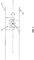
- FIG. 1 illustrates a pivot joint (e.g., a u-joint) operatively coupled to and positioned between a base and a motion platform.
- the motion platform 100 is able to move relative to base 105.
- the u-joint 110 permits the motion platform 100 to at least rotate about a roll axis "x" and a pitch axis "z,” where the pitch axis "z” is perpendicular to FIG. 1 .
- U-joints are well known in the art.
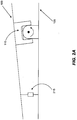
- FIGs. 2A and 2B illustrate an exemplary active device and a u-joint, where both are coupled to and positioned between a base and a motion platform.
- forces must be applied to the motion platform 100.
- this force is supplied by a plurality of active devices 215.
- FIG. 2 is a side view, so that only one of said plurality of active devices 215 is visible.
- Each of the plurality of active devices 215 are spaced a desired distance "d" from the u-joint 110, as illustrated.
- the plurality of active devices 215 will be illustrated and described in greater detail below.
- Each of the plurality of active devices 215 may be linear actuators, for example, but not limited to pneumatic or hydraulic piston/cylinder type actuators, or electromagnetic or electromechanical actuators. They are referred to herein as "active" devices because they receive an input that results in an output that, in turn, directly acts on another component.
- the input is typically an electric signal that causes pressurized air or hydraulic fluid, respectively, to drive a piston rod into or out of a cylinder, thereby reducing or increasing the overall length of the actuator.
- the output is a force acting to pull the motion platform 100 towards the base 105 ( FIG. 2A ).
- the output is a force acting to push the motion platform 100 away from the base 105 ( FIG. 2B ).
- the combined force acting on the motion platform 100 by each of the plurality of active devices 215 will cause the motion platform 100 to rotate a corresponding angular distance about the roll axis "z" and/or the pitch axis "z” by virtue of the u-joint 110.
- Linear actuators including pneumatic and hydraulic piston/cylinder type, and electromagnetic and electromechanical type linear actuators are, in and of themselves, well known in the art.
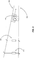
- FIG. 3 illustrates an exemplary active device, a u-joint and a transducer, all of which are coupled to and positioned between a base and a motion platform.
- each of a plurality of transducers 320 e.g., passive transducers
- the u-joint 110 is aligned with the u-joint 110 and a corresponding one of the plurality of active devices (e.g., linear actuators).
- FIG. 3 is also a side view and, therefore, only one of the plurality of active devices 215 and only one of the plurality of transducers 320 are illustrated.
- FIG. 3 also illustrates that each one of the plurality of transducers 320 is aligned with the u-joint 110 and a corresponding one of the plurality of active devices 215 such that the connection points A, B (between the active device, motion platform and base) and connection points C, D (between the transducer, motion platform and base) fall in the same geometric plane as does the pivot point E of u-joint 110.
- this particular alignment of each active device 215, its corresponding transducer 320 and the pivot point E of u-joint 110 is very important and it provides a significant benefit.
- each transducer 320 remains proportional to the state of the corresponding active device 215.
- the active devices 215 are pneumatic or hydraulic linear piston/cylinder type actuators
- the position of the rod within the cylinder of each actuator compared to the output of the corresponding transducer 320 remains proportional.
- any computation that is based on the output of each transducer 320 is significantly simplified, whether the computation is used to provide feedback signals for controlling the position and/or orientation of the motion platform 100 or for protecting the active devices 215 from exceeding their operational range. As stated above, simplifying this computation is important particularly in high speed applications such as vehicle simulators and theme park attractions.
- FIG. 4 is a top-down view of FIG. 3 , and further illustrates the relative positioning of an active device, a corresponding passive transducer and the u-joint, in accordance with exemplary embodiments of the present invention.
- the aforementioned connection points A. B. C and D and the pivot point E of the u-joint 110 all fall in the same geometric plane.
- each active device 215, its corresponding transducer 320 and the u-joint 110 appear to be arranged in a linear configuration along line L.
- each of the transducers 320 is positioned between the corresponding active device 215 and the u-joint 110, as illustrated in FIG. 3 and FIG. 4 .
- the specific location of each transducer 320 in this embodiment may depend on such factors as size, cost and the location of other components associated with the motion platform 100.
- each of the plurality of active devices 215 are positioned between the corresponding transducer 320 and the u-joint, as long as the aforementioned connection points A, B, C and D are in the same geometric plane as the pivot point E of u-joint 110.
- the pivot point E of u-joint 110 is positioned between each of the plurality of active devices 215 and its corresponding transducer 320, as long as the aforementioned connection points A, B, C and D are in the same geometric plane as the pivot point E of u-joint 110.
- the relative positioning of each of the plurality of active devices 215 with its corresponding transducer 320 and the u-joint may vary, as long as the aforementioned connection points A, B, C and D are in the same geometric plane as the pivot point E of u-joint 110.
- the computation based on the output of one transducer may be different from the computation based on the output of another transducer, due to the fact that the two transducers have different positions relative to the corresponding active device. Nevertheless, the computations are simplified as long as the aforementioned connection points A, B, C and D are in the same geometric plane as the pivot point E of u-joint 110.
- FIG. 5 illustrates an exemplary one of the plurality of transducers 320.
- the exemplary transducer 320 comprises a magnetic element 525 and a pair of sensors 530.
- the magnetic element 525 is capable of moving back and forth between the sensors 530 by virtue of a piston 535 which moves back and forth due to the movement of the motion platform 100 to which the transducer 320 is connected, as described above.
- Each of the sensors 530 is capable of detecting the magnetic field produced by the magnetic element 525 when the magnetic clement 525 is in close proximity to the sensor.
- Each sensor 530 is also capable of outputting an electric signal (e.g., a voltage or current) when the magnetic field is detected or the magnitude of the magnetic field exceeds a pre-determined threshold.
- an electric signal e.g., a voltage or current
- the transducer 320 can be calibrated such that the electric output signal generated by one sensor may indicate that the length of the corresponding active device 215 is at or approaching one end of its operational range (e.g., maximum extension), and wherein the electric output signal generated by the other sensor may indicate that the length of the active device 215 is at or approaching the other end of its operational range (e.g., maximum retraction).
- one sensor may indicate that the length of the corresponding active device 215 is at or approaching one end of its operational range (e.g., maximum extension)
- the electric output signal generated by the other sensor may indicate that the length of the active device 215 is at or approaching the other end of its operational range (e.g., maximum retraction).
- each passive transducer 320 is to prevent the corresponding active device 215 from exceeding its operational range, then the passive transducer 320 illustrated in FIG. 5 , as described above, is appropriate. If the primary function of the passive transducer 320 is to provide position and/or orientation feedback control for the motion platform 100, other types of passive transducers may be preferred, such as, but not limited to linear potentiometers, linear optical (incremental or absolute), linear-to-rotary (incremental or absolute), magneto-restrictive (absolute), ultrasonic (absolute), magnetic encoded (incremental or absolute), laser interferometer (absolute), capacitive absolute, inductive absolute and eddy current type transducers.
- linear potentiometers linear optical (incremental or absolute), linear-to-rotary (incremental or absolute), magneto-restrictive (absolute), ultrasonic (absolute), magnetic encoded (incremental or absolute), laser interferometer (absolute), capacitive absolute, inductive absolute and eddy
- the transducers 320 are passive devices. As such, the transducers 320 are, herein below, referred to as passive transducers.
- the transducers 320 are passive because they do not receive an input signal, as do the active devices 215. and they play no part in exerting any force on the motion platform 100, as do the active devices 215.
- Passive transducers such as the one illustrated in FIG. 5 , are generally well known in the art. It will be understood, however, that the scope of the present invention is not limited to the use of passive transducers, as some transducers that require power to operate could be employed as an alternative to the passive transducers described above.
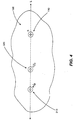
- FIG. 6 is a top-down view illustrating the relative positioning of a first active device, passive transducer pair (hereafter “first pair 635”): a second active device, passive transducer pair (hereafter “second pair 640”) and a u-joint 110, all of which arc operatively coupled to and positioned between a base and a motion.
- FIG. 7 is a perspective view of first pair 635. second pair 640 and the u-joint 110 illustrated in FIG. 6.
- FIGs. 6 and 7 illustrate a preferred embodiment of the present invention in terms of the number of active devices and passive transducers. In other words, there are two active device, passive transducer pairs in a preferred embodiment. However, the scope of the present invention is not limited thereto.
- each of the plurality of active devices 215 are aligned with a corresponding one of the plurality of passive transducers 320 and the u-joint 110, such that each of the first pair 635 and the second pair 640 aligns in a linear configuration with the u-joint 110 in the top-down view, as illustrated in FIG. 6 . Because each pair 635 and 640 must align with the u-joint 110 in a linear configuration, the line L passing through the first pair 635 is separated by an angle 0 from the line L' passing through the second pair 640.
- the shape of the motion platform 100 is shown as being circular. However, the present invention is not limited to any particular motion platform shape.
- the motion platform 100 When the active device of the first pair 635 and the active device of the second pair 640 extend (i.e., increase in length) by the same amount, the motion platform 100 will rotate about the pitch axis "z.”
- the active device of the first pair 635 and the active device of the second pair 640 extend or retract in direct opposition (i.e., one extends by the same amount the other retracts), the motion platform 100 will rotate purely about the roll axis "x.”
- the active device of the first pair 635 or the active device of the second pair 640 extends or retracts while the other does not extend or retract, the motion platform 100 will rotate partially about the roll axis "x," and partially about the pitch axis "z.” Regardless, because of the alignment of each of the plurality of active devices 215 with a corresponding one of the plurality of passive transducers and the u-joint 110, as described
Landscapes
- Engineering & Computer Science (AREA)
- General Engineering & Computer Science (AREA)
- Mechanical Engineering (AREA)
- Transmission Devices (AREA)
- Apparatuses For Generation Of Mechanical Vibrations (AREA)
- Measurement Of Length, Angles, Or The Like Using Electric Or Magnetic Means (AREA)
- Length Measuring Devices With Unspecified Measuring Means (AREA)
- General Electrical Machinery Utilizing Piezoelectricity, Electrostriction Or Magnetostriction (AREA)
- Measurement Of Velocity Or Position Using Acoustic Or Ultrasonic Waves (AREA)
Applications Claiming Priority (2)
| Application Number | Priority Date | Filing Date | Title |
|---|---|---|---|
| US201361799146P | 2013-03-15 | 2013-03-15 | |
| PCT/US2014/024854 WO2014151056A1 (en) | 2013-03-15 | 2014-03-12 | Motion platform configuration |
Publications (3)
| Publication Number | Publication Date |
|---|---|
| EP2973500A1 EP2973500A1 (en) | 2016-01-20 |
| EP2973500A4 EP2973500A4 (en) | 2016-12-07 |
| EP2973500B1 true EP2973500B1 (en) | 2019-10-30 |
Family
ID=51521562
Family Applications (1)
| Application Number | Title | Priority Date | Filing Date |
|---|---|---|---|
| EP14768483.1A Active EP2973500B1 (en) | 2013-03-15 | 2014-03-12 | Motion platform configuration |
Country Status (10)
| Country | Link |
|---|---|
| US (1) | US9097383B2 (enExample) |
| EP (1) | EP2973500B1 (enExample) |
| JP (1) | JP6448613B2 (enExample) |
| KR (1) | KR102154065B1 (enExample) |
| CN (1) | CN105378818B (enExample) |
| CA (1) | CA2904064C (enExample) |
| DK (1) | DK2973500T3 (enExample) |
| MY (1) | MY172041A (enExample) |
| SG (1) | SG11201507059VA (enExample) |
| WO (1) | WO2014151056A1 (enExample) |
Families Citing this family (5)
| Publication number | Priority date | Publication date | Assignee | Title |
|---|---|---|---|---|
| TWM515057U (zh) * | 2015-04-24 | 2016-01-01 | Injoy Motion Corp | 一種氣動驅動的兩軸運動平台 |
| US10350450B2 (en) * | 2016-01-13 | 2019-07-16 | John Stelmach | Lateral tilting treadmill systems |
| CN109300353B (zh) * | 2016-10-18 | 2021-07-27 | 浙江海洋大学 | 模拟海上作业工况的海洋工程试验平台装置 |
| US9927312B1 (en) * | 2017-03-03 | 2018-03-27 | Bertec Corporation | Motion base for displacing a force measurement assembly |
| KR102125444B1 (ko) | 2018-10-30 | 2020-06-22 | 한국로봇융합연구원 | 하중보상 메커니즘을 적용한 모션플랫폼 |
Family Cites Families (12)
| Publication number | Priority date | Publication date | Assignee | Title |
|---|---|---|---|---|
| US5605462A (en) * | 1991-07-12 | 1997-02-25 | Denne Developments Ltd. | Motion imparting apparatus |
| US5980256A (en) * | 1993-10-29 | 1999-11-09 | Carmein; David E. E. | Virtual reality system with enhanced sensory apparatus |
| US6354838B1 (en) * | 1996-11-18 | 2002-03-12 | Mariah Vision3 Entertainment, Inc. | Interactive race car simulator system |
| US6758623B2 (en) * | 2001-12-07 | 2004-07-06 | Mts Systems Corporation | High axial stiffness swivel joint |
| US7094157B2 (en) * | 2003-07-22 | 2006-08-22 | Oceaneering International, Inc. | Amusement ride vehicle with pneumatically actuated cabin and motion base |
| US8065951B2 (en) * | 2005-02-15 | 2011-11-29 | P.I. Engineering, Inc. | Servo-controlled tipping platform and motion control system therefor |
| US7806697B2 (en) * | 2005-08-15 | 2010-10-05 | Cae Inc. | Method and apparatus for damping vibrations in a motion simulation platform |
| CN100507324C (zh) * | 2006-03-29 | 2009-07-01 | 宝山钢铁股份有限公司 | 大流量比例控制水阀 |
| CN101457633B (zh) * | 2008-12-25 | 2010-12-15 | 浙江大学 | 活塞位移电反馈负载口独立控制液压冲击器 |
| US20110177873A1 (en) * | 2010-01-15 | 2011-07-21 | Joseph Daniel Sebelia | Potential Energy Assisted Motion Simulator Mechanism and Method |
| DE102010025740A1 (de) * | 2010-06-30 | 2012-01-05 | Illinois Tool Works Inc. | Pulverversorgungssvorrichtung und Verfahren zum automatischen Reinigen einer Pulverversorgungseinrichtung |
| EP3413290B8 (en) | 2011-05-11 | 2026-05-06 | Falcon's Beyond Global, LLC | Trackless dark ride vehicle, system, and method |
-
2014
- 2014-03-12 US US14/206,030 patent/US9097383B2/en active Active
- 2014-03-12 KR KR1020157028572A patent/KR102154065B1/ko active Active
- 2014-03-12 CN CN201480021671.4A patent/CN105378818B/zh active Active
- 2014-03-12 WO PCT/US2014/024854 patent/WO2014151056A1/en not_active Ceased
- 2014-03-12 DK DK14768483.1T patent/DK2973500T3/da active
- 2014-03-12 JP JP2016501658A patent/JP6448613B2/ja active Active
- 2014-03-12 CA CA2904064A patent/CA2904064C/en active Active
- 2014-03-12 EP EP14768483.1A patent/EP2973500B1/en active Active
- 2014-03-12 MY MYPI2015002217A patent/MY172041A/en unknown
- 2014-03-12 SG SG11201507059VA patent/SG11201507059VA/en unknown
Non-Patent Citations (1)
| Title |
|---|
| None * |
Also Published As
| Publication number | Publication date |
|---|---|
| US9097383B2 (en) | 2015-08-04 |
| WO2014151056A1 (en) | 2014-09-25 |
| KR20160016757A (ko) | 2016-02-15 |
| HK1219798A1 (zh) | 2017-04-13 |
| CN105378818B (zh) | 2018-06-29 |
| CA2904064A1 (en) | 2014-09-25 |
| SG11201507059VA (en) | 2015-10-29 |
| CA2904064C (en) | 2021-01-26 |
| CN105378818A (zh) | 2016-03-02 |
| JP2016512899A (ja) | 2016-05-09 |
| MY172041A (en) | 2019-11-12 |
| KR102154065B1 (ko) | 2020-09-21 |
| JP6448613B2 (ja) | 2019-01-09 |
| US20140261092A1 (en) | 2014-09-18 |
| EP2973500A1 (en) | 2016-01-20 |
| EP2973500A4 (en) | 2016-12-07 |
| DK2973500T3 (da) | 2020-01-06 |
Similar Documents
| Publication | Publication Date | Title |
|---|---|---|
| EP2973500B1 (en) | Motion platform configuration | |
| CN110497385B (zh) | 精密测量六自由度并联机构动平台位姿的装置及方法 | |
| US9776678B2 (en) | Self-balancing vehicles | |
| US8985354B2 (en) | Movement system configured for moving a payload in a plurality of directions | |
| JP4852561B2 (ja) | センサ装置付きジョイスティック | |
| EP1292813B1 (en) | System for performing tests on intelligent road vehicles | |
| JP2014161991A (ja) | ロボットの移動機構及びそれを備えるロボット | |
| US10576617B1 (en) | Service robot having movable center of mass | |
| WO2012083792A1 (zh) | 一种二自由度操纵杆驱动试验装置及其控制方法 | |
| CN103998925A (zh) | 适应性磁耦合系统 | |
| JP2018030225A5 (enExample) | ||
| CN103253300A (zh) | 车辆用转向装置 | |
| WO2012066678A1 (ja) | 自律移動体 | |
| CN103086272A (zh) | 配置为沿多个方向移动负载的移动系统 | |
| CN103692452B (zh) | 一种用于多自由度机械臂的制动装置及控制方法 | |
| CN106142050A (zh) | 一种车轮高低差自适应的移动机器人 | |
| CN102141469B (zh) | 一种二自由度操纵杆驱动试验装置的安装方法 | |
| CN107526339A (zh) | 一种高速高精度目标平面运动模拟装置 | |
| CN118068838A (zh) | 机器人感知系统及感知定位方法 | |
| HK1219798B (zh) | 運動平臺配置 | |
| US11808567B1 (en) | System and method for detecting span alignment within a mechanized irrigation system | |
| WO2016202448A1 (en) | Traction arrangement comprising a belt and method for driving the same | |
| KR20130097480A (ko) | 회전 조향이 가능한 차량용 선회 장치 및 이를 포함하는 차량 | |
| JP6314428B2 (ja) | ロボット、制御装置及びロボットシステム | |
| CN106556804A (zh) | 三轴微机械磁场传感器 |
Legal Events
| Date | Code | Title | Description |
|---|---|---|---|
| PUAI | Public reference made under article 153(3) epc to a published international application that has entered the european phase |
Free format text: ORIGINAL CODE: 0009012 |
|
| 17P | Request for examination filed |
Effective date: 20151013 |
|
| AK | Designated contracting states |
Kind code of ref document: A1 Designated state(s): AL AT BE BG CH CY CZ DE DK EE ES FI FR GB GR HR HU IE IS IT LI LT LU LV MC MK MT NL NO PL PT RO RS SE SI SK SM TR |
|
| AX | Request for extension of the european patent |
Extension state: BA ME |
|
| DAX | Request for extension of the european patent (deleted) | ||
| A4 | Supplementary search report drawn up and despatched |
Effective date: 20161109 |
|
| RIC1 | Information provided on ipc code assigned before grant |
Ipc: A63G 31/16 20060101ALI20161103BHEP Ipc: F16M 11/04 20060101ALI20161103BHEP Ipc: A63G 31/04 20060101ALI20161103BHEP Ipc: G09B 9/00 20060101ALI20161103BHEP Ipc: F16M 11/18 20060101ALI20161103BHEP Ipc: F16M 11/12 20060101ALI20161103BHEP Ipc: G09B 9/02 20060101AFI20161103BHEP Ipc: F16M 11/14 20060101ALI20161103BHEP |
|
| RIC1 | Information provided on ipc code assigned before grant |
Ipc: A63G 31/04 20060101ALI20181219BHEP Ipc: A63G 31/16 20060101ALI20181219BHEP Ipc: G09B 9/02 20060101AFI20181219BHEP Ipc: F16M 11/18 20060101ALI20181219BHEP Ipc: F16M 11/14 20060101ALI20181219BHEP Ipc: G09B 9/00 20060101ALI20181219BHEP Ipc: F16M 11/04 20060101ALI20181219BHEP Ipc: F16M 11/12 20060101ALI20181219BHEP |
|
| GRAP | Despatch of communication of intention to grant a patent |
Free format text: ORIGINAL CODE: EPIDOSNIGR1 |
|
| STAA | Information on the status of an ep patent application or granted ep patent |
Free format text: STATUS: GRANT OF PATENT IS INTENDED |
|
| INTG | Intention to grant announced |
Effective date: 20190515 |
|
| RAP1 | Party data changed (applicant data changed or rights of an application transferred) |
Owner name: OCEANEERING INTERNATIONAL, INC. |
|
| GRAS | Grant fee paid |
Free format text: ORIGINAL CODE: EPIDOSNIGR3 |
|
| GRAA | (expected) grant |
Free format text: ORIGINAL CODE: 0009210 |
|
| STAA | Information on the status of an ep patent application or granted ep patent |
Free format text: STATUS: THE PATENT HAS BEEN GRANTED |
|
| AK | Designated contracting states |
Kind code of ref document: B1 Designated state(s): AL AT BE BG CH CY CZ DE DK EE ES FI FR GB GR HR HU IE IS IT LI LT LU LV MC MK MT NL NO PL PT RO RS SE SI SK SM TR |
|
| REG | Reference to a national code |
Ref country code: GB Ref legal event code: FG4D |
|
| REG | Reference to a national code |
Ref country code: CH Ref legal event code: EP |
|
| REG | Reference to a national code |
Ref country code: AT Ref legal event code: REF Ref document number: 1196989 Country of ref document: AT Kind code of ref document: T Effective date: 20191115 |
|
| REG | Reference to a national code |
Ref country code: DE Ref legal event code: R096 Ref document number: 602014055979 Country of ref document: DE |
|
| REG | Reference to a national code |
Ref country code: IE Ref legal event code: FG4D |
|
| REG | Reference to a national code |
Ref country code: DK Ref legal event code: T3 Effective date: 20191218 |
|
| REG | Reference to a national code |
Ref country code: NO Ref legal event code: T2 Effective date: 20191030 |
|
| REG | Reference to a national code |
Ref country code: NL Ref legal event code: FP |
|
| REG | Reference to a national code |
Ref country code: CH Ref legal event code: NV Representative=s name: VALIPAT S.A. C/O BOVARD SA NEUCHATEL, CH |
|
| REG | Reference to a national code |
Ref country code: LT Ref legal event code: MG4D |
|
| PG25 | Lapsed in a contracting state [announced via postgrant information from national office to epo] |
Ref country code: FI Free format text: LAPSE BECAUSE OF FAILURE TO SUBMIT A TRANSLATION OF THE DESCRIPTION OR TO PAY THE FEE WITHIN THE PRESCRIBED TIME-LIMIT Effective date: 20191030 Ref country code: BG Free format text: LAPSE BECAUSE OF FAILURE TO SUBMIT A TRANSLATION OF THE DESCRIPTION OR TO PAY THE FEE WITHIN THE PRESCRIBED TIME-LIMIT Effective date: 20200130 Ref country code: PL Free format text: LAPSE BECAUSE OF FAILURE TO SUBMIT A TRANSLATION OF THE DESCRIPTION OR TO PAY THE FEE WITHIN THE PRESCRIBED TIME-LIMIT Effective date: 20191030 Ref country code: GR Free format text: LAPSE BECAUSE OF FAILURE TO SUBMIT A TRANSLATION OF THE DESCRIPTION OR TO PAY THE FEE WITHIN THE PRESCRIBED TIME-LIMIT Effective date: 20200131 Ref country code: SE Free format text: LAPSE BECAUSE OF FAILURE TO SUBMIT A TRANSLATION OF THE DESCRIPTION OR TO PAY THE FEE WITHIN THE PRESCRIBED TIME-LIMIT Effective date: 20191030 Ref country code: LV Free format text: LAPSE BECAUSE OF FAILURE TO SUBMIT A TRANSLATION OF THE DESCRIPTION OR TO PAY THE FEE WITHIN THE PRESCRIBED TIME-LIMIT Effective date: 20191030 Ref country code: ES Free format text: LAPSE BECAUSE OF FAILURE TO SUBMIT A TRANSLATION OF THE DESCRIPTION OR TO PAY THE FEE WITHIN THE PRESCRIBED TIME-LIMIT Effective date: 20191030 Ref country code: LT Free format text: LAPSE BECAUSE OF FAILURE TO SUBMIT A TRANSLATION OF THE DESCRIPTION OR TO PAY THE FEE WITHIN THE PRESCRIBED TIME-LIMIT Effective date: 20191030 Ref country code: PT Free format text: LAPSE BECAUSE OF FAILURE TO SUBMIT A TRANSLATION OF THE DESCRIPTION OR TO PAY THE FEE WITHIN THE PRESCRIBED TIME-LIMIT Effective date: 20200302 |
|
| PG25 | Lapsed in a contracting state [announced via postgrant information from national office to epo] |
Ref country code: RS Free format text: LAPSE BECAUSE OF FAILURE TO SUBMIT A TRANSLATION OF THE DESCRIPTION OR TO PAY THE FEE WITHIN THE PRESCRIBED TIME-LIMIT Effective date: 20191030 Ref country code: HR Free format text: LAPSE BECAUSE OF FAILURE TO SUBMIT A TRANSLATION OF THE DESCRIPTION OR TO PAY THE FEE WITHIN THE PRESCRIBED TIME-LIMIT Effective date: 20191030 Ref country code: IS Free format text: LAPSE BECAUSE OF FAILURE TO SUBMIT A TRANSLATION OF THE DESCRIPTION OR TO PAY THE FEE WITHIN THE PRESCRIBED TIME-LIMIT Effective date: 20200229 |
|
| PG25 | Lapsed in a contracting state [announced via postgrant information from national office to epo] |
Ref country code: AL Free format text: LAPSE BECAUSE OF FAILURE TO SUBMIT A TRANSLATION OF THE DESCRIPTION OR TO PAY THE FEE WITHIN THE PRESCRIBED TIME-LIMIT Effective date: 20191030 |
|
| PG25 | Lapsed in a contracting state [announced via postgrant information from national office to epo] |
Ref country code: EE Free format text: LAPSE BECAUSE OF FAILURE TO SUBMIT A TRANSLATION OF THE DESCRIPTION OR TO PAY THE FEE WITHIN THE PRESCRIBED TIME-LIMIT Effective date: 20191030 Ref country code: RO Free format text: LAPSE BECAUSE OF FAILURE TO SUBMIT A TRANSLATION OF THE DESCRIPTION OR TO PAY THE FEE WITHIN THE PRESCRIBED TIME-LIMIT Effective date: 20191030 Ref country code: CZ Free format text: LAPSE BECAUSE OF FAILURE TO SUBMIT A TRANSLATION OF THE DESCRIPTION OR TO PAY THE FEE WITHIN THE PRESCRIBED TIME-LIMIT Effective date: 20191030 |
|
| REG | Reference to a national code |
Ref country code: DE Ref legal event code: R097 Ref document number: 602014055979 Country of ref document: DE |
|
| REG | Reference to a national code |
Ref country code: AT Ref legal event code: MK05 Ref document number: 1196989 Country of ref document: AT Kind code of ref document: T Effective date: 20191030 |
|
| PG25 | Lapsed in a contracting state [announced via postgrant information from national office to epo] |
Ref country code: IT Free format text: LAPSE BECAUSE OF FAILURE TO SUBMIT A TRANSLATION OF THE DESCRIPTION OR TO PAY THE FEE WITHIN THE PRESCRIBED TIME-LIMIT Effective date: 20191030 Ref country code: SM Free format text: LAPSE BECAUSE OF FAILURE TO SUBMIT A TRANSLATION OF THE DESCRIPTION OR TO PAY THE FEE WITHIN THE PRESCRIBED TIME-LIMIT Effective date: 20191030 Ref country code: SK Free format text: LAPSE BECAUSE OF FAILURE TO SUBMIT A TRANSLATION OF THE DESCRIPTION OR TO PAY THE FEE WITHIN THE PRESCRIBED TIME-LIMIT Effective date: 20191030 |
|
| PLBE | No opposition filed within time limit |
Free format text: ORIGINAL CODE: 0009261 |
|
| STAA | Information on the status of an ep patent application or granted ep patent |
Free format text: STATUS: NO OPPOSITION FILED WITHIN TIME LIMIT |
|
| 26N | No opposition filed |
Effective date: 20200731 |
|
| REG | Reference to a national code |
Ref country code: NO Ref legal event code: MMEP |
|
| PG25 | Lapsed in a contracting state [announced via postgrant information from national office to epo] |
Ref country code: MC Free format text: LAPSE BECAUSE OF FAILURE TO SUBMIT A TRANSLATION OF THE DESCRIPTION OR TO PAY THE FEE WITHIN THE PRESCRIBED TIME-LIMIT Effective date: 20191030 |
|
| REG | Reference to a national code |
Ref country code: CH Ref legal event code: PL |
|
| REG | Reference to a national code |
Ref country code: DK Ref legal event code: EBP Effective date: 20200331 |
|
| REG | Reference to a national code |
Ref country code: NL Ref legal event code: MM Effective date: 20200401 |
|
| PG25 | Lapsed in a contracting state [announced via postgrant information from national office to epo] |
Ref country code: AT Free format text: LAPSE BECAUSE OF FAILURE TO SUBMIT A TRANSLATION OF THE DESCRIPTION OR TO PAY THE FEE WITHIN THE PRESCRIBED TIME-LIMIT Effective date: 20191030 Ref country code: SI Free format text: LAPSE BECAUSE OF FAILURE TO SUBMIT A TRANSLATION OF THE DESCRIPTION OR TO PAY THE FEE WITHIN THE PRESCRIBED TIME-LIMIT Effective date: 20191030 |
|
| REG | Reference to a national code |
Ref country code: BE Ref legal event code: MM Effective date: 20200331 |
|
| PG25 | Lapsed in a contracting state [announced via postgrant information from national office to epo] |
Ref country code: LU Free format text: LAPSE BECAUSE OF NON-PAYMENT OF DUE FEES Effective date: 20200312 Ref country code: NL Free format text: LAPSE BECAUSE OF NON-PAYMENT OF DUE FEES Effective date: 20200401 |
|
| PG25 | Lapsed in a contracting state [announced via postgrant information from national office to epo] |
Ref country code: NO Free format text: LAPSE BECAUSE OF NON-PAYMENT OF DUE FEES Effective date: 20200331 Ref country code: IE Free format text: LAPSE BECAUSE OF NON-PAYMENT OF DUE FEES Effective date: 20200312 Ref country code: LI Free format text: LAPSE BECAUSE OF NON-PAYMENT OF DUE FEES Effective date: 20200331 Ref country code: CH Free format text: LAPSE BECAUSE OF NON-PAYMENT OF DUE FEES Effective date: 20200331 |
|
| PG25 | Lapsed in a contracting state [announced via postgrant information from national office to epo] |
Ref country code: BE Free format text: LAPSE BECAUSE OF NON-PAYMENT OF DUE FEES Effective date: 20200331 |
|
| PG25 | Lapsed in a contracting state [announced via postgrant information from national office to epo] |
Ref country code: DK Free format text: LAPSE BECAUSE OF NON-PAYMENT OF DUE FEES Effective date: 20200331 |
|
| PG25 | Lapsed in a contracting state [announced via postgrant information from national office to epo] |
Ref country code: TR Free format text: LAPSE BECAUSE OF FAILURE TO SUBMIT A TRANSLATION OF THE DESCRIPTION OR TO PAY THE FEE WITHIN THE PRESCRIBED TIME-LIMIT Effective date: 20191030 Ref country code: MT Free format text: LAPSE BECAUSE OF FAILURE TO SUBMIT A TRANSLATION OF THE DESCRIPTION OR TO PAY THE FEE WITHIN THE PRESCRIBED TIME-LIMIT Effective date: 20191030 Ref country code: CY Free format text: LAPSE BECAUSE OF FAILURE TO SUBMIT A TRANSLATION OF THE DESCRIPTION OR TO PAY THE FEE WITHIN THE PRESCRIBED TIME-LIMIT Effective date: 20191030 |
|
| PG25 | Lapsed in a contracting state [announced via postgrant information from national office to epo] |
Ref country code: MK Free format text: LAPSE BECAUSE OF FAILURE TO SUBMIT A TRANSLATION OF THE DESCRIPTION OR TO PAY THE FEE WITHIN THE PRESCRIBED TIME-LIMIT Effective date: 20191030 |
|
| P01 | Opt-out of the competence of the unified patent court (upc) registered |
Effective date: 20230530 |
|
| PGFP | Annual fee paid to national office [announced via postgrant information from national office to epo] |
Ref country code: DE Payment date: 20250521 Year of fee payment: 12 |
|
| PGFP | Annual fee paid to national office [announced via postgrant information from national office to epo] |
Ref country code: GB Payment date: 20250522 Year of fee payment: 12 |
|
| PGFP | Annual fee paid to national office [announced via postgrant information from national office to epo] |
Ref country code: FR Payment date: 20260331 Year of fee payment: 13 |