EP2963784A1 - Struktur zur montage eines sensors in einer motoreinheit - Google Patents
Struktur zur montage eines sensors in einer motoreinheit Download PDFInfo
- Publication number
- EP2963784A1 EP2963784A1 EP14757362.0A EP14757362A EP2963784A1 EP 2963784 A1 EP2963784 A1 EP 2963784A1 EP 14757362 A EP14757362 A EP 14757362A EP 2963784 A1 EP2963784 A1 EP 2963784A1
- Authority
- EP
- European Patent Office
- Prior art keywords
- rotor
- engine
- hall
- crankshaft
- partition wall
- Prior art date
- Legal status (The legal status is an assumption and is not a legal conclusion. Google has not performed a legal analysis and makes no representation as to the accuracy of the status listed.)
- Granted
Links
Images


Classifications
-
- H—ELECTRICITY
- H02—GENERATION; CONVERSION OR DISTRIBUTION OF ELECTRIC POWER
- H02K—DYNAMO-ELECTRIC MACHINES
- H02K29/00—Motors or generators having non-mechanical commutating devices, e.g. discharge tubes or semiconductor devices
- H02K29/06—Motors or generators having non-mechanical commutating devices, e.g. discharge tubes or semiconductor devices with position sensing devices
- H02K29/08—Motors or generators having non-mechanical commutating devices, e.g. discharge tubes or semiconductor devices with position sensing devices using magnetic effect devices, e.g. Hall-plates, magneto-resistors
-
- H—ELECTRICITY
- H02—GENERATION; CONVERSION OR DISTRIBUTION OF ELECTRIC POWER
- H02K—DYNAMO-ELECTRIC MACHINES
- H02K11/00—Structural association of dynamo-electric machines with electric components or with devices for shielding, monitoring or protection
- H02K11/20—Structural association of dynamo-electric machines with electric components or with devices for shielding, monitoring or protection for measuring, monitoring, testing, protecting or switching
- H02K11/21—Devices for sensing speed or position, or actuated thereby
- H02K11/215—Magnetic effect devices, e.g. Hall-effect or magneto-resistive elements
-
- H—ELECTRICITY
- H02—GENERATION; CONVERSION OR DISTRIBUTION OF ELECTRIC POWER
- H02K—DYNAMO-ELECTRIC MACHINES
- H02K7/00—Arrangements for handling mechanical energy structurally associated with dynamo-electric machines, e.g. structural association with mechanical driving motors or auxiliary dynamo-electric machines
- H02K7/18—Structural association of electric generators with mechanical driving motors, e.g. with turbines
- H02K7/1807—Rotary generators
- H02K7/1815—Rotary generators structurally associated with reciprocating piston engines
-
- H—ELECTRICITY
- H02—GENERATION; CONVERSION OR DISTRIBUTION OF ELECTRIC POWER
- H02K—DYNAMO-ELECTRIC MACHINES
- H02K9/00—Arrangements for cooling or ventilating
- H02K9/02—Arrangements for cooling or ventilating by ambient air flowing through the machine
- H02K9/04—Arrangements for cooling or ventilating by ambient air flowing through the machine having means for generating a flow of cooling medium
- H02K9/06—Arrangements for cooling or ventilating by ambient air flowing through the machine having means for generating a flow of cooling medium with fans or impellers driven by the machine shaft
-
- F—MECHANICAL ENGINEERING; LIGHTING; HEATING; WEAPONS; BLASTING
- F01—MACHINES OR ENGINES IN GENERAL; ENGINE PLANTS IN GENERAL; STEAM ENGINES
- F01P—COOLING OF MACHINES OR ENGINES IN GENERAL; COOLING OF INTERNAL-COMBUSTION ENGINES
- F01P1/00—Air cooling
- F01P1/06—Arrangements for cooling other engine or machine parts
-
- F—MECHANICAL ENGINEERING; LIGHTING; HEATING; WEAPONS; BLASTING
- F02—COMBUSTION ENGINES; HOT-GAS OR COMBUSTION-PRODUCT ENGINE PLANTS
- F02D—CONTROLLING COMBUSTION ENGINES
- F02D41/00—Electrical control of supply of combustible mixture or its constituents
- F02D41/009—Electrical control of supply of combustible mixture or its constituents using means for generating position or synchronisation signals
-
- H—ELECTRICITY
- H02—GENERATION; CONVERSION OR DISTRIBUTION OF ELECTRIC POWER
- H02K—DYNAMO-ELECTRIC MACHINES
- H02K5/00—Casings; Enclosures; Supports
- H02K5/04—Casings or enclosures characterised by the shape, form or construction thereof
- H02K5/18—Casings or enclosures characterised by the shape, form or construction thereof with ribs or fins for improving heat transfer
Definitions
- the present invention relates to an engine unit sensor installation structure in which a position detection sensor used to detect a rotational position of a rotor of a rotary electric machine is provided at a position adjacent to a crankcase.
- an engine unit that uses a rotary electric machine for AC power generation provided on one end in an axis direction of a crankshaft as a start motor used for the engine start.
- a position detection sensor used to detect a rotational position of the rotor is provided (for example, refer to Japanese Unexamined Patent Application, First Publication No. 2010-200421 ).
- permanent magnets are attached on the inner circumferential surface of a rotor having a cylindrical shape with a bottom, the rotor being connected to an end portion of a crankshaft such that different magnetic pole faces alternately appear along the circumferential direction, and a stator is provided on an non-rotating part inside of the rotor such that the magnetic pole is opposed to a permanent magnet of the rotor.
- the stator of the rotary electric machine includes a plurality of teeth radially extending, and coils of three phases are each wound around predetermined one of the teeth.
- a Hall IC unit as a sensor that detects the change of magnetic flux is attached close to a tip portion of each of U-phase, V-phase, and W-phase magnetic poles (teeth), and the position of the magnet, that is, the rotational position of the rotor is detected based on a signal output from the Hall IC unit.
- the Hall IC unit is configured such that a Hall IC element is buried in a resin.
- the rotor having a cylindrical shape with a bottom is attached to the end portion of the crankshaft such that the opening of the rotor is directed toward the crankcase, and the stator and the Hall IC unit provided on the stator are attached to the outer lateral surface of a wall portion of the crankcase.
- An engine cover attached to the wall portion of the crankcase covers the outside of the stator and rotor.
- the Hall IC unit with the stator is attached to the wall portion of the crankcase which becomes a high temperature when the engine is driven, in a case where the cooling efficiency of the engine body of a water-cooling engine or the like is not high (or in a case where the sensor is not a valuable one having a high cooling efficiency), the cooling manner becomes a problem.
- An object of an aspect of the present invention is to provide an engine unit sensor installation structure capable of enhancing the cooling performance of an installation part of a Hall IC unit and stably detecting a rotational position by the Hall IC unit even in a case where a high cooling efficiency of the engine body is not expected.
- An engine unit sensor installation structure employs the following configurations in order to achieve the aforementioned object.
- the Hall IC unit since it is possible to regulate the flow of a high-temperature lubrication oil in the crank chamber into the engine cover by the partition wall, the Hall IC unit is attached to the engine cover that does not easily become high temperatures, and the peripheral part of the partition wall is efficiently cooled by the forced cooling air, it is possible to enhance the cooling performance of the installation part of the Hall IC unit. Accordingly, it is possible to stably detect a rotational position by the Hall IC unit even in a case where a high cooling efficiency of the engine body is not expected.
- an arrow FR indicates the front of a vehicle
- an arrow UP indicates the upside of the vehicle
- an arrow LF indicates the left side of the vehicle.
- FIG. 1 is a view showing the lateral side of a motorcycle 1 provided with an engine unit 2.
- the engine unit 2 is provided at the center in the vehicle body front and rear direction, a seat 3 on which an occupant is seated is provided upper rearward of the engine unit 2, and a fuel tank 4 is provided below the seat 3.
- a front wheel Wf is supported rotatably by a front fork 5, and a steering handle 6 is provided upward of the front fork 5.
- a rear wheel Wr is supported swingably by a vehicle body frame via a swing arm 7.
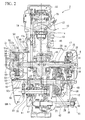
- FIG. 2 is a cross sectional view of the engine unit 2 corresponding to an A-A cross section of FIG. 1 .
- the engine unit 2 is configured as an integrated block of a multistep transmission 11 and a reciprocating engine 10 as an internal combustion engine, and transmission of power between the engine 10 and the transmission 11 is available via a centrifugal clutch 8 and a transmission clutch 12.
- a piston 14 is slidably fitted into a cylinder bore of a cylinder block 13, and the piston 14 is connected to the crankshaft 16 via a con rod 15.
- the cylinder block 13 is provided on a vehicle in a substantially horizontal attitude extending frontward of the vehicle body with respect to the crankshaft 16.
- the crankshaft 16 is supported rotatably via a shaft bearing 18 to a crankcase 17 integrally connected to one end portion (rear end portion) of the cylinder block 13.
- a cylinder head 20 that forms a combustion chamber 19 with the piston 14 is attached to the other end portion (front end portion) of the cylinder block 13.
- an ignition device 21 is provided on the cylinder head 20 so as to face the inside of the combustion chamber 19.
- a valve moving device 22 is provided on an end portion of the cylinder head 20. The valve moving device 22 performs open and close driving of intake and exhaust valves (not shown) in cooperation with the crankshaft 16.
- a crank web 23 is provided on both sides in an axis direction of a connection portion (crank pin) with the con rod 15 on the crankshaft 16.
- a crank chamber 17a in the crankcase 17 houses substantially the whole area of the crankshaft 16.
- the centrifugal clutch 8 is provided on the outer circumference of one end portion (end portion on the right side of FIG. 2 ) in an axis direction of the crankshaft 16.
- the centrifugal clutch 8 includes a clutch inner 24 integrally fixed to the one end portion of the crankshaft 16, a clutch outer 25 rotatably supported on the outer circumference on the one end side of the crankshaft 16, and a centrifugal weight 26 that rotates integrally with the clutch inner 24 and makes the clutch inner 24 and the clutch outer 25 be in a connecting state by a centrifugal force.
- the centrifugal clutch 8 outputs a rotational power of the crankshaft 16 to the clutch outer 25 when the rotational speed of the crankshaft 16 reaches a predetermined speed or more.
- an output gear 28 that engages with an input gear 27 of the transmission clutch 12 is connected integrally rotatably to the clutch outer 25.
- Amain shaft 29 and a counter shaft 30 of the transmission 11 are provided in parallel with the crankshaft 16 at a vehicle rearward position of a rotation center O of the crankshaft 16 in the crankcase 17.
- the main shaft 29 and the counter shaft 30 are each rotatably supported in the crankcase 17 via a shaft bearing (reference numeral is omitted).
- the main shaft 29 is provided at a position adjacent to the vehicle rear of the crankshaft 16.
- the counter shaft 30 is provided at a position adjacent to the vehicle rear of the main shaft 29.
- Amain transmission gear group M1 is provided on the main shaft 29 of the transmission 11.
- a counter gear group M2 that engages with the main transmission gear group M1 is provided on the counter shaft 30 of the transmission 11.
- the input gear 27 and the transmission clutch 12 each engaging with the output gear 28 on the crankshaft 16 side are provided on one end portion in an axis direction of the main shaft 29.
- the input gear 27 is rotatably supported on the outer circumference of the main shaft 29.
- an output sprocket 33 is attached to another end portion in an axis direction of the counter shaft 30.
- a chain (not shown) used for power transmission is hung on the output sprocket 33.
- the rotation of the counter shaft 30 is transmitted via the chain to the rear wheel Wr as a drive wheel.
- drive transmission gears of the main transmission gear group M1 and the counter gear group M2 are selected by a rotational operation of a shift drum (not shown) provided in the crankcase 17, and thereby an arbitrary transmission gear step (gear position) including a neutral position is set.
- the transmission clutch 12 includes a clutch outer 35 having a cylindrical shape with a bottom rotatably supported on the main shaft 29 in a state where the clutch outer 35 is integrally connected to the input gear 27, a clutch inner 36 having a substantially discoid shape connected by spline engagement to the main shaft 29, a plurality of drive friction plates 37 integrally rotatably caught by the clutch outer 35, a plurality of following friction plates 38 that are integrally rotatably caught by the clutch inner 36 and frictionally come into contact with the drive friction plate 37, a clutch spring (not shown) that biases the drive friction plate 37 and the following friction plate 38 in a compressive contact direction, and an operation plate 40 that performs a release operation of the biasing force of a clutch spring that acts between the drive friction plate 37 and the following friction plate 38.
- a clutch outer 35 having a cylindrical shape with a bottom rotatably supported on the main shaft 29 in a state where the clutch outer 35 is integrally connected to the input gear 27, a clutch inner 36 having a substantially disco
- the drive friction plates 37 of the clutch outer 35 and the following friction plates 38 of the clutch inner 36 are arranged alternately in an axis direction, realize power transmission between the clutch outer 35 and the clutch inner 36 by being pressed to each other in response to the biasing force of the clutch spring, and cut off power transmission between the clutch outer 35 and the clutch inner 36 by a release operation of the biasing force of the clutch spring by the operation plate 40.
- a kick spindle 42 of a kick starter 41 is rotatably attached to the rearward lower portion of the crankcase 17.
- the kick spindle 42 transmits the rotation to the crankshaft 16 only when a kick pedal 43 is kicked down.
- ACG starter 50 ⁇ A rotary electric machine having a function as an AC generator and a function as a start motor of the engine 10 is provided on another end side of the crankshaft 16 that protrudes from the opening 17b of the crankcase 17.
- An engine cover 51 having a recess shape that is attached by bolt fastening or the like to the lateral wall of the crankcase 17 covers another end of the crankshaft 16, and the front surface side and the circumferential area of the ACG starter 50.
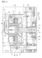
- FIG. 3 is an enlarged view showing an installation part of the ACG starter 50 of FIG. 2 .
- the ACG starter 50 includes a rotor 52 having a cylindrical shape with a bottom that is attached to an end portion of the crankshaft 16 and a stator 53 provided on the inner circumferential side of the rotor 52.
- the rotor 52 is fixed to the crankshaft 16 such that a bottom wall 52a is located on the lateral wall side of the crankcase 17.
- the stator 53 is fixed by bolt fastening or the like to the inner lateral surface of a bottom wall 51a of the engine cover 51.
- Permanent magnets 54 are attached on the inner circumferential surface of the rotor 52 such that different magnetic pole faces (N-pole face and S-pole face) that direct in a shaft center direction of the rotor 52 alternately appear along the circumferential direction.
- the permanent magnets 54 are arranged on the inner circumferential side of the rotor 52 such that a magnetization direction is directed along a radial direction of the rotor 52.
- the permanent magnet 54 is a magnet in which a plurality of magnet pieces each having a strip shape is attached to the inner circumferential surface of the rotor 52; however, the permanent magnet 54 may be a ferromagnetic having a cylindrical shape magnetized such that different magnetic pole faces alternately appear along the circumferential direction.
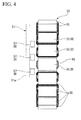
- FIG. 4 is a view in which the stator 53 is seen from a direction perpendicular to the shaft center of the rotor 52.
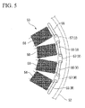
- FIG. 5 is a view in which the stator 53 is seen from a direction along the shaft center of the rotor 52.
- the stator 53 includes a plurality of teeth 55 each protruding in a radial direction, and one of U-phase, V-phase, and W-phase coils 56 is wound around each of the teeth 55.
- the front end surface of each of the teeth 55 is configured to face the magnetic pole face of the permanent magnet 54 on the inner circumference of the rotor 52 with a micro gap.
- a Hall IC unit 57 that detects the change of magnetic flux in accordance with the movement of the permanent magnet 54 is attached to a position that faces from the lateral side (from a direction along the axis direction) the rotational path of the permanent magnet 54, of the inner lateral surface of the bottom wall 51a of the engine cover 51.
- one of the Hall IC units 57 is provided at a position adjacent to each of the U-phase, V-phase, and W-phase magnetic poles (teeth 55) of the stator 53.
- each of the Hall IC units 57 has a configuration in which a Hall IC element 57a is buried inside of a resin 57b.
- one of the Hall IC elements 57a that corresponds to the resin 57b of one package of each of the Hall IC units 57 is buried; however, three Hall IC elements 57a each used for one of U-phase, V-phase, and W-phase may be buried in the resin 57b as one package.
- each of the Hall IC units 57 is attached to the bottom wall 51a of the engine cover 51 such that a magnetic flux detection direction is directed along the radial direction of the rotor 52. As shown in FIG. 3 , the Hall IC unit 57 attached to the bottom wall 51a in this way faces the inner circumferential surface of the end edge of the rotor 52 where the permanent magnet 54 is not provided. Each of the Hall IC units 57 is provided at a position that faces the inside of the opening of the rotor 52 in the engine cover 51.
- the Hall IC units 57 with the permanent magnets 54 on the rotor 52 configure a position detection sensor 58 used to detect a rotational position of the rotor 52.
- a signal detected by the position detection sensor 58 is output to a current control device (not shown) of the ACG starter 50 and is used to control energization (control a commutation timing) of the U-phase, V-phase, and W-phase coils 56 in the current control device.
- a protrusion 61 that becomes a detection target used to detect an ignition timing of the engine 10 is formed on the outer circumferential surface of the rotor 52.
- An electromagnetic pickup sensor 62 is attached to a position that faces a rotational path of the protrusion 61 of the inner circumferential surface of the engine cover 51.
- a detection signal detected by the pickup sensor 62 is output to a control device (not shown) used for engine control.
- the detection signal detected by the pickup sensor 62 is also used to detect the rotational angle of the crankshaft 16 with each signal detected by the three Hall IC units 57 described above. That is, since the pickup sensor 62 can detect a specific angle of the crankshaft 16 with respect to the engine cover 51, by counting pulses of the detection signal of each of the Hall IC units 57 after the detection signal is output from the pickup sensor 62, it is possible to detect angles of a plurality of points from a starting point at a specific angle of the crankshaft 16.
- the above-described three Hall IC units 57 each detecting the change of magnetic flux are provided at a frontward upper position relative to the crankshaft 16 in the engine cover 51.
- an outside air introduction hole 69 is formed on a substantially central part of the bottom wall 51a of the engine cover 51 so as to face the end portion in the axis direction of the crankshaft 16.
- An air guiding duct 59 used to introduce a traveling wind through the outside air guiding hole 69 into the engine cover 51 when the vehicle is traveling is attached on the vehicle outside of the bottom wall 51a.
- the front end portion that introduces the outside air of the air guiding duct 59 directs toward the front of the vehicle body.
- a discharge port 60 used to discharge the traveling wind introduced into the engine cover 51 is provided on the rearward wall of the engine cover 51 relative to the crankshaft 16.
- a partition wall 63 having a circular plate shape that separates the crank chamber 17a from an inner space of the engine cover 51 is attached to the opening 17b of the crankcase 17 through which the end portion of the crankshaft 16 protrudes.
- the partition wall 63 is formed of a heat-resistant resin material.
- the outer circumferential edge portion of the partition wall 63 is fixed to the edge portion of the opening 17b of the crankcase 17 in a state where an O ring 64 as a seal member is interposed between the outer circumferential edge portion of the partition wall 63 and the edge portion of the opening 17b.
- a penetrating hole 65 into which the end portion of the crankshaft 16 is inserted is formed on the central part of the partition wall 63.
- An oil seal 66 is provided in a space between the penetrating hole 65 and the outer circumferential surface of the crankshaft 16. The oil seal 66 keeps the space liquid-tight in a state where rotation of the crankshaft 16 is allowed.
- a plurality of penetrating holes 70 each connecting two sides of the bottom wall 52a are provided on the bottom wall 52a of the rotor 52 of the ACG starter 50. Further, a plurality of fins 67 are provided in a protruding manner on the outer lateral surface of the bottom wall 52a of the rotor 52.
- the fin 67 functions as a rotary vane that introduces a cooling air through the outer peripheral area of the rotor 52 and the penetrating hole 70 when the rotor 52 rotates and that sends the cooling air toward the partition wall 63.
- the fins 67 provided in a protruding manner on the bottom wall 52a of the rotor 52 configure an air guiding member for forced cooling.
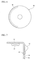
- FIG. 6 is a front view of the partition wall 63.
- a flow adjusting vane 68 having an arc shape that adjusts the flow of the cooling air that is sent from the fin 67 of the rotor 52 is provided in a protruding manner on a surface that faces the bottom wall 52a of the rotor 52 of the partition wall 63.
- the flow adjusting vane 68 of the present embodiment is provided radially outwardly of the formation position of the fin 67 of the rotor 52 and mutually overlaps in an axis direction with the fin 67 of the rotor 52.
- the cooling air when the cooling air is blown to the front surface of the partition wall 63 from the fin 67, according to a guiding function by the flow adjusting vane 68, the cooling air is guided to the vehicle body rearward area along the front surface of the partition wall 63. In this way, the cooling air that flows along the front surface of the partition wall 63 cools the partition wall 63 and the circumferential area of the partition wall 63 and then is exhausted to the outside of the engine cover 51 through the discharge port 60.
- the traveling wind that travels to the partition wall 63 through the penetrating hole 70 gains an air blowing effect by the fin 67 and cools the partition wall 63 and the circumferential area of the partition wall 63 as described above.
- the cooling air that travels to the circumferential area of the Hall IC unit 57 cools the Hall IC unit 57 and then flows around to the outer circumference of the rotor 52. Part of the cooling air is discharged to the outside directly through the discharge port 60. The rest of the cooling air gains suction and air blowing effects of the fin 67 and is blown to the front surface of the partition wall 63.
- the fin 67 as the air guiding member provided on the bottom wall 52a of the rotor 52 may be formed of a metal plate as a separate body of the rotor 52 and may be fixed to the bottom wall 52a of the rotor 52 by a rivet 45 or the like.
- the partition wall 63 is attached to the opening 17b of the crankcase 17 through which the end portion of the crankshaft 16 protrudes, and the crank chamber 17a and the inner space of the engine cover 51 are liquid tightly sealed. Therefore, it is possible to prevent lubrication oil that flows in the crankcase 17 from flowing into the engine cover 51. Accordingly, lubrication oil that becomes a high-temperature when the engine 10 is driven does not flow around into the circumferential area of the Hall IC unit 57.
- the rotor 52 of the ACG starter 50 is attached to the crankshaft 16 such that the bottom wall 52a is located on the crankcase 17 side, and the stator 53 of the ACG starter 50 and the Hall IC unit 57 are attached to the inner surface of the bottom wall 51 a of the engine cover 51. Therefore, the stator 53 and the Hall IC unit 57 are kept a low-temperature state by the engine cover 51 that is directly exposed to the outside air and is easily cooled.
- a plurality of fins 67 each functioning as a rotary vane are provided on the bottom wall 51a of the rotor 52 that integrally rotates with the crankshaft 16. Therefore, the cooling air introduced through the outer circumferential area of the rotor 52 and the penetrating hole 70 can be blown to the partition wall 63. Therefore, it is possible to efficiently cool the partition wall 63 and the wall of the crankcase 17 of the circumferential area of the partition wall 63 by the cooling air. Accordingly, the heat on the crankcase 17 side becomes further difficult to be transmitted to the Hall IC unit 57.
- a flow adjusting vane 68 that guides the cooling air which is blown from the fin 67 of the rotor 52 to the rear of the vehicle body along the front surface of the partition wall 63 is provided in a protruding manner on the surface of the partition wall 63 that faces the bottom wall 52a of the rotor 52. Therefore, it is possible to further efficiently cool the partition wall 63 exposed to the heat of the crankcase 17 by the cooperation of the fin 67 and the flow adjusting vane 68.
- part of a traveling wind introduced into the engine cover 51 through the air guiding duct 59 directly flows into the front surface of the partition wall 63 through the penetrating hole 70 of the rotor 52, and part of the rest of the traveling wind flows into the circumferential area of the Hall IC unit 57 in the opening of the rotor 52. Since the traveling wind cools the partition wall 63 and the Hall IC unit 57 and then is discharged to the outside through the discharge port 60, it is possible to further efficiently cool a region that tends to be a high temperature in the engine cover 51 by the traveling wind when the vehicle is traveling.
- the traveling wind introduced into the engine cover 51 through the air guiding duct 59 also cools the pickup sensor 62 attached to the inner surface of the circumferential wall of the engine cover 51.
- the engine unit 2 of the present embodiment is not one in which the Hall IC unit 57 is attached to a portion that directly faces the magnetic pole face of the permanent magnet 54 of each of the U-phase, V-phase, and W-phase magnetic poles of the stator 53.
- each of the Hall IC units 57 is provided on the lateral portion in the axis direction of the permanent magnet 54 magnetized along the radial direction of the rotor 52 such that the magnetic flux detection direction is parallel to the magnetization direction of the permanent magnet 54 (directed along the radial direction of the rotor 52). Therefore, it is possible to efficiently detect the magnetic flux change of each magnetic pole of the stator 53 associated with the movement of the permanent magnet 54.
- the Hall IC unit 57 since the Hall IC unit 57 is arranged close to the inner circumferential surface of the end edge of the rotor 52, it is possible to further efficiently detect the magnetic flux change of each magnetic pole of the stator 53.
- the Hall IC unit 57 it is possible to detect the change of magnetic flux corresponding to each of the U-phase, V-phase, and W-phase by the Hall IC unit 57 described above, it is possible to detect the ignition timing of the engine 10 by the pickup sensor 62 provided on the circumferential wall of the engine cover 51 and the protrusion 61 provided in a protruding manner on the outer circumference of the rotor 52, and further, it is possible to detect the rotational angle of the crankshaft 16 based on the detection signal of each of the Hall IC units 57 and the detection signal of the pickup sensor 62. Moreover, since both of the Hall IC unit 57 and the pickup sensor 62 are not easily influenced by the heat of the crankcase 17 described above, it is possible to always maintain stable detection performances.
- the rotational angle of the crankshaft 16 detected based on each of detection signals of the Hall IC units 57 and the pickup sensor 62 is used when performing a rotation control of the ACG starter 50, for example, such that the stop position (angle) of the crankshaft 16 is a position suitable for the next restart of the engine 10 when idling is stopped.
- the partition wall 63 attached to the opening 17b of the crankcase 17 is formed of a heat-resistant resin material, there is an advantage that it is possible to efficiently cut off high-temperature heat of the crankcase 17 by the partition wall 63 and that it is possible to easily form in an integrated manner an air guiding unit such as the flow adjusting vane 68 on the partition wall 63.
- FIG. 8 is an enlarged view showing an installation part of the ACG starter 50 according to a third embodiment of the present invention.
- the basic configuration of the engine unit of the present embodiment is substantially similar to that of the first embodiment; however, there is a difference that a rotary vane 77 as a separate body of the rotor 52 is integrally attached to the crankshaft 16 while in the first embodiment, the fin 67 that functions as a rotary vane is integrally provided on the bottom wall 52a of the rotor 52.
- the rotary vane 77 is one in which a plurality of fins 67 is provided in a protruding manner on a support plate 75 having a circular plate shape fixed to the crankshaft 16 and is attached to the crankshaft 16 such that the rotary vane 77 is located in a space between the partition wall 63 and the bottom wall 52a of the rotor 52.
- the rotary vane 77 configures the air guiding member that guides a cooling air to the space between the partition wall 63 and the bottom wall 52a of the rotor 52.
- the flow adjusting vane 68 is provided in a protruding manner on the front surface side of the partition wall 63, similarly to the first embodiment.
- the flow adjusting vane 68 is arranged radially outwardly of the rotary vane 77 and is configured to overlap in the axis direction with the rotary vane 77.
- the engine unit of the present embodiment can basically provide advantages substantially similar to the first embodiment. Further, it is not necessary to apply a special process on the rotor 52 and the partition wall 63, and what is required is just attaching the rotary vane 77 to the crankshaft 16. Therefore, production is easy, and parts of the existing type of vehicle are available as is. Accordingly, there is a further advantage that the production cost can be reduced.
- the flow adjusting vane 68 that adjusts the flow of the cooling air sent from the rotary vane 77 may be provided on the partition wall 63, similarly to the first embodiment.
- FIG. 9 is a diagram in which the inner circumferential surface of the rotor 52 is expanded and is schematically shown according to a fourth embodiment of the present invention.
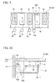
- FIG. 10 is a schematic enlarged cross sectional view of an installation part of the ACG starter 50 corresponding to FIG. 3 of the fourth embodiment.
- FIG. 11 is a view in which the stator 53 is seen from a direction along the shaft center of the rotor 52.
- the engine unit of the fourth embodiment does not employ the pickup sensor 62 shown in FIG. 3 and FIG. 8 in order to detect the ignition timing of the engine and is configured such that an indicator magnet 91 (permanent magnet) for the detection target is provided on part of the permanent magnet 54 of the ACG starter 50 and that the magnetic flux change of a magnet array including the indicator magnet 91 is detected by the Hall IC unit 57A.
- the Hall IC unit 57A and the magnet array of the permanent magnet 54 including the indicator magnet 91 configure a position detection sensor 58A that detects the rotational position of the rotor 52.
- the permanent magnet 54 and the U-phase, V-phase, and W-phase Hall IC units 57 configure the position detection sensor 58, similarly to other embodiments described above.
- the permanent magnet 54 provided on the inner circumferential surface of the rotor 52 is arranged such that magnetized faces alternately appear along the circumferential direction, similarly to other embodiments described above.
- the energization control Hall IC units 57 are attached to the inner surface of the bottom wall 51a of the engine cover 51 at a lateral positon of the permanent magnet 54 and the U-phase, V-phase, and W-phase magnetic poles.
- the Hall IC elements of the energization control Hall IC units 57 are also arranged such that the magnetic flux detection direction is directed along the radial direction of the rotor 52.
- the indicator magnet 91 is attached to the end portion in the axis direction of arbitrary magnet piece of the permanent magnet 54 such that a magnetic pole that is different from a magnetic pole which directs toward the rotor center of the permanent magnet 54 directs toward the rotor center (for example, such that when the magnetic pole of the permanent magnet 54 is the S-pole, the N-pole directs toward the rotor center).
- a magnetic pole that is different from a magnetic pole which directs toward the rotor center of the permanent magnet 54 directs toward the rotor center (for example, such that when the magnetic pole of the permanent magnet 54 is the S-pole, the N-pole directs toward the rotor center).
- three magnetic poles of the same pole type in the case of the example of FIG. 9 , N-pole continues forward and rearward of the indicator magnet 91.
- a specific position (angle) on the crankshaft can be determined.
- the specific position on the crankshaft 16 is associated with the ignition position of the engine.
- An ignition timing detection Hall IC unit 57A is attached to the inner lateral surface of the bottom wall 51a of the engine cover 51, similarly to the energization control Hall IC unit 57.
- a magnetic flux introduction member 92 such as a magnetic metal is provided at a position that faces a path of the magnetic pole face of the indicator magnet 91 with a micro gap.
- the magnetic flux introduction member 92 is arranged such that one end of the magnetic flux introduction member 92 faces the path of the magnetic pole face of the indicator magnet 91 and that the other end of the magnetic flux introduction member 92 faces the magnetic flux detection unit of the Hall IC unit 57A.
- the engine unit of the fourth embodiment it is possible to detect the ignition timing of the engine by the Hall IC unit 57A and the magnet array of the end portion of the permanent magnet 54 including the indicator magnet 91, and it is possible to accurately detect the rotational angle of the crankshaft 16 by using output signals of the Hall IC unit 57A and the energization control Hall IC units 57.
- These functions are similar to those of the above embodiments in which a pickup sensor is used to detect the ignition timing of the engine.
- the Hall IC units 57, 57A are gathered and arranged on the bottom wall 51a of the engine cover 51 that is easily cooled by the outside air, the cooling efficiencies of the Hall IC units 57, 57A can be enhanced, and the structure of the engine cover 51 is simplified to make the whole apparatus compact.
- the present embodiment similarly to the first embodiment, it is possible to efficiently cool not only the energization control Hall IC units 57 but also the ignition timing detection Hall IC unit 57A. Accordingly, in the engine unit, since the cooling performances of the installation part of the Hall IC units 57, 57A are enhanced, it is possible to stably detect a rotational position by the Hall IC units 57, 57A even in a case where a high cooling efficiency of the engine body is not expected.
- the partition wall 63 that blocks the opening 17b of the crankcase 17 is formed of a heat-resistant resin; however, the partition wall 63 may be formed of a metal material.
- the heat generated on the crankcase 17 side is further easily diffused to the outside through the partition wall 63, and it is also possible to consider cooling the engine by using the air guiding part.
Landscapes
- Engineering & Computer Science (AREA)
- Power Engineering (AREA)
- Microelectronics & Electronic Packaging (AREA)
- Combined Controls Of Internal Combustion Engines (AREA)
- Motor Or Generator Cooling System (AREA)
Applications Claiming Priority (2)
| Application Number | Priority Date | Filing Date | Title |
|---|---|---|---|
| JP2013039617 | 2013-02-28 | ||
| PCT/JP2014/051660 WO2014132719A1 (ja) | 2013-02-28 | 2014-01-27 | エンジンユニットのセンサ設置構造 |
Publications (3)
| Publication Number | Publication Date |
|---|---|
| EP2963784A1 true EP2963784A1 (de) | 2016-01-06 |
| EP2963784A4 EP2963784A4 (de) | 2017-01-11 |
| EP2963784B1 EP2963784B1 (de) | 2018-10-10 |
Family
ID=51427993
Family Applications (1)
| Application Number | Title | Priority Date | Filing Date |
|---|---|---|---|
| EP14757362.0A Active EP2963784B1 (de) | 2013-02-28 | 2014-01-27 | Struktur zur montage eines sensors in einer motoreinheit |
Country Status (3)
| Country | Link |
|---|---|
| EP (1) | EP2963784B1 (de) |
| JP (1) | JP5942035B2 (de) |
| WO (1) | WO2014132719A1 (de) |
Cited By (5)
| Publication number | Priority date | Publication date | Assignee | Title |
|---|---|---|---|---|
| EP3312420A1 (de) * | 2016-10-20 | 2018-04-25 | Yamaha Hatsudoki Kabushiki Kaisha | Motor |
| FR3087966A1 (fr) * | 2018-10-26 | 2020-05-01 | Valeo Equipements Electriques Moteur | Bloc de commande d'une machine electrique tournante et procede de montage d'un tel bloc de commande |
| US11035698B2 (en) | 2018-03-29 | 2021-06-15 | Honda Motor Co., Ltd. | Crank angle detection device |
| US11761368B2 (en) | 2021-09-02 | 2023-09-19 | Kawasaki Motors, Ltd. | Engine unit |
| EP4275939A1 (de) * | 2022-05-12 | 2023-11-15 | Kawasaki Motors, Ltd. | Fahrzeug und kühlstruktur für elektrische komponente |
Families Citing this family (2)
| Publication number | Priority date | Publication date | Assignee | Title |
|---|---|---|---|---|
| JP7480913B2 (ja) | 2021-04-13 | 2024-05-10 | 日産自動車株式会社 | 内燃機関のダンパ冷却構造 |
| JP7595610B2 (ja) * | 2022-03-29 | 2024-12-06 | 本田技研工業株式会社 | 発電機構造 |
Family Cites Families (9)
| Publication number | Priority date | Publication date | Assignee | Title |
|---|---|---|---|---|
| JPH0691718B2 (ja) * | 1990-06-01 | 1994-11-14 | 株式会社三ツ葉電機製作所 | 磁石発電機の冷却ファンおよびその製造方法 |
| JPH0578175U (ja) * | 1992-03-17 | 1993-10-22 | 富士重工業株式会社 | エンジン駆動ゼネレータ |
| JP4020275B2 (ja) * | 1997-10-22 | 2007-12-12 | 株式会社ミツバ | 電動機兼用発電機 |
| EP1233175B1 (de) * | 1999-11-24 | 2006-12-13 | Mitsuba Corporation | Anlasser, anlasssteuervorrichtung und kurbelwellenwinkelgeber einer brennkraftmaschine |
| JP2005104248A (ja) * | 2003-09-29 | 2005-04-21 | Honda Motor Co Ltd | ハイブリッド車両におけるパワーユニット |
| JP2010200421A (ja) * | 2009-02-23 | 2010-09-09 | Mitsuba Corp | アウタロータ型の回転電機 |
| JP5519302B2 (ja) * | 2010-01-19 | 2014-06-11 | 本田技研工業株式会社 | 鞍乗型車両 |
| WO2013011595A1 (ja) | 2011-07-15 | 2013-01-24 | 株式会社 昭和螺旋管製作所 | バルジ加工用の金属ベローズ成形方法、及び、その金属ベローズ成形装置 |
| JP2013027252A (ja) * | 2011-07-25 | 2013-02-04 | Denso Trim Kk | 始動発電機 |
-
2014
- 2014-01-27 JP JP2015502810A patent/JP5942035B2/ja not_active Expired - Fee Related
- 2014-01-27 EP EP14757362.0A patent/EP2963784B1/de active Active
- 2014-01-27 WO PCT/JP2014/051660 patent/WO2014132719A1/ja not_active Ceased
Cited By (5)
| Publication number | Priority date | Publication date | Assignee | Title |
|---|---|---|---|---|
| EP3312420A1 (de) * | 2016-10-20 | 2018-04-25 | Yamaha Hatsudoki Kabushiki Kaisha | Motor |
| US11035698B2 (en) | 2018-03-29 | 2021-06-15 | Honda Motor Co., Ltd. | Crank angle detection device |
| FR3087966A1 (fr) * | 2018-10-26 | 2020-05-01 | Valeo Equipements Electriques Moteur | Bloc de commande d'une machine electrique tournante et procede de montage d'un tel bloc de commande |
| US11761368B2 (en) | 2021-09-02 | 2023-09-19 | Kawasaki Motors, Ltd. | Engine unit |
| EP4275939A1 (de) * | 2022-05-12 | 2023-11-15 | Kawasaki Motors, Ltd. | Fahrzeug und kühlstruktur für elektrische komponente |
Also Published As
| Publication number | Publication date |
|---|---|
| JP5942035B2 (ja) | 2016-06-29 |
| EP2963784B1 (de) | 2018-10-10 |
| JPWO2014132719A1 (ja) | 2017-02-02 |
| EP2963784A4 (de) | 2017-01-11 |
| WO2014132719A1 (ja) | 2014-09-04 |
Similar Documents
| Publication | Publication Date | Title |
|---|---|---|
| EP2963784B1 (de) | Struktur zur montage eines sensors in einer motoreinheit | |
| CN105247778B (zh) | 在车辆中使用的四冲程发动机单元和车辆 | |
| US9637008B2 (en) | Generator motor unit, power output engine, and vehicle | |
| JP5744978B2 (ja) | ハイブリッド車または電気自動車用の電気機械 | |
| EP2999097B1 (de) | Rotierende elektrische vorrichtung für eine leistungsarbeitsmaschine | |
| JP2001238426A (ja) | モータ | |
| US8492914B2 (en) | Crank-web mounted linearly segmented starter generator system | |
| WO2012169156A1 (ja) | 内燃機関制御用信号出力機能付き回転機、及び内燃機関制御用信号出力機能付き始動モータ | |
| CN110344982B (zh) | 跨骑型车辆 | |
| EP3640079B1 (de) | Fahrzeug | |
| JP2009159792A (ja) | 車両の駆動装置、及びそれを備える鞍乗型車両 | |
| JP4851184B2 (ja) | 回転電機システム | |
| JP5990479B2 (ja) | エンジンユニットのセンサ設置構造 | |
| ITTO20010313A1 (it) | Motorino d'avviamento/generatore. | |
| EP3640080B1 (de) | Fahrzeug | |
| EP3640078B1 (de) | Fahrzeug | |
| JP2002159164A (ja) | ブラシレス多相交流電機およびその通電制御装置 | |
| JP7540317B2 (ja) | エンジン | |
| JP6413199B2 (ja) | ワンウェイクラッチ | |
| JP2015218625A (ja) | エンジンユニットおよび鞍乗り型車両 | |
| JP6912678B2 (ja) | Mt型シフトペダル付エンジンユニット、及び同エンジンユニットを備えたストラドルドビークル | |
| WO2006130434A1 (en) | Magnetorheological fluid clutch with stationary coil | |
| JP2014168345A (ja) | クランク軸の位置検出構造 | |
| JP2008045562A (ja) | 自動二輪車 | |
| JP2009216015A (ja) | アキシャルギャップ型モータジェネレータ |
Legal Events
| Date | Code | Title | Description |
|---|---|---|---|
| PUAI | Public reference made under article 153(3) epc to a published international application that has entered the european phase |
Free format text: ORIGINAL CODE: 0009012 |
|
| 17P | Request for examination filed |
Effective date: 20150903 |
|
| AK | Designated contracting states |
Kind code of ref document: A1 Designated state(s): AL AT BE BG CH CY CZ DE DK EE ES FI FR GB GR HR HU IE IS IT LI LT LU LV MC MK MT NL NO PL PT RO RS SE SI SK SM TR |
|
| AX | Request for extension of the european patent |
Extension state: BA ME |
|
| DAX | Request for extension of the european patent (deleted) | ||
| A4 | Supplementary search report drawn up and despatched |
Effective date: 20161208 |
|
| RIC1 | Information provided on ipc code assigned before grant |
Ipc: F02N 11/04 20060101ALI20161202BHEP Ipc: F01P 1/06 20060101ALI20161202BHEP Ipc: H02K 9/06 20060101ALI20161202BHEP Ipc: H02K 7/18 20060101ALI20161202BHEP Ipc: H02K 11/00 20160101AFI20161202BHEP Ipc: F02D 35/00 20060101ALI20161202BHEP Ipc: H02K 7/00 20060101ALI20161202BHEP Ipc: F02D 45/00 20060101ALI20161202BHEP Ipc: F02D 41/00 20060101ALI20161202BHEP |
|
| REG | Reference to a national code |
Ref country code: DE Ref legal event code: R079 Ref document number: 602014033843 Country of ref document: DE Free format text: PREVIOUS MAIN CLASS: H02K0011000000 Ipc: H02K0029080000 |
|
| RIC1 | Information provided on ipc code assigned before grant |
Ipc: H02K 5/18 20060101ALI20180328BHEP Ipc: H02K 29/08 20060101AFI20180328BHEP Ipc: H02K 7/18 20060101ALI20180328BHEP Ipc: H02K 9/06 20060101ALI20180328BHEP Ipc: H02K 11/215 20160101ALI20180328BHEP |
|
| GRAP | Despatch of communication of intention to grant a patent |
Free format text: ORIGINAL CODE: EPIDOSNIGR1 |
|
| STAA | Information on the status of an ep patent application or granted ep patent |
Free format text: STATUS: GRANT OF PATENT IS INTENDED |
|
| INTG | Intention to grant announced |
Effective date: 20180525 |
|
| GRAS | Grant fee paid |
Free format text: ORIGINAL CODE: EPIDOSNIGR3 |
|
| GRAA | (expected) grant |
Free format text: ORIGINAL CODE: 0009210 |
|
| STAA | Information on the status of an ep patent application or granted ep patent |
Free format text: STATUS: THE PATENT HAS BEEN GRANTED |
|
| AK | Designated contracting states |
Kind code of ref document: B1 Designated state(s): AL AT BE BG CH CY CZ DE DK EE ES FI FR GB GR HR HU IE IS IT LI LT LU LV MC MK MT NL NO PL PT RO RS SE SI SK SM TR |
|
| REG | Reference to a national code |
Ref country code: GB Ref legal event code: FG4D |
|
| REG | Reference to a national code |
Ref country code: AT Ref legal event code: REF Ref document number: 1052397 Country of ref document: AT Kind code of ref document: T Effective date: 20181015 Ref country code: CH Ref legal event code: EP |
|
| REG | Reference to a national code |
Ref country code: IE Ref legal event code: FG4D |
|
| REG | Reference to a national code |
Ref country code: DE Ref legal event code: R096 Ref document number: 602014033843 Country of ref document: DE |
|
| REG | Reference to a national code |
Ref country code: NL Ref legal event code: MP Effective date: 20181010 |
|
| REG | Reference to a national code |
Ref country code: LT Ref legal event code: MG4D |
|
| REG | Reference to a national code |
Ref country code: AT Ref legal event code: MK05 Ref document number: 1052397 Country of ref document: AT Kind code of ref document: T Effective date: 20181010 |
|
| PG25 | Lapsed in a contracting state [announced via postgrant information from national office to epo] |
Ref country code: NL Free format text: LAPSE BECAUSE OF FAILURE TO SUBMIT A TRANSLATION OF THE DESCRIPTION OR TO PAY THE FEE WITHIN THE PRESCRIBED TIME-LIMIT Effective date: 20181010 |
|
| PG25 | Lapsed in a contracting state [announced via postgrant information from national office to epo] |
Ref country code: BG Free format text: LAPSE BECAUSE OF FAILURE TO SUBMIT A TRANSLATION OF THE DESCRIPTION OR TO PAY THE FEE WITHIN THE PRESCRIBED TIME-LIMIT Effective date: 20190110 Ref country code: ES Free format text: LAPSE BECAUSE OF FAILURE TO SUBMIT A TRANSLATION OF THE DESCRIPTION OR TO PAY THE FEE WITHIN THE PRESCRIBED TIME-LIMIT Effective date: 20181010 Ref country code: IS Free format text: LAPSE BECAUSE OF FAILURE TO SUBMIT A TRANSLATION OF THE DESCRIPTION OR TO PAY THE FEE WITHIN THE PRESCRIBED TIME-LIMIT Effective date: 20190210 Ref country code: AT Free format text: LAPSE BECAUSE OF FAILURE TO SUBMIT A TRANSLATION OF THE DESCRIPTION OR TO PAY THE FEE WITHIN THE PRESCRIBED TIME-LIMIT Effective date: 20181010 Ref country code: FI Free format text: LAPSE BECAUSE OF FAILURE TO SUBMIT A TRANSLATION OF THE DESCRIPTION OR TO PAY THE FEE WITHIN THE PRESCRIBED TIME-LIMIT Effective date: 20181010 Ref country code: LV Free format text: LAPSE BECAUSE OF FAILURE TO SUBMIT A TRANSLATION OF THE DESCRIPTION OR TO PAY THE FEE WITHIN THE PRESCRIBED TIME-LIMIT Effective date: 20181010 Ref country code: NO Free format text: LAPSE BECAUSE OF FAILURE TO SUBMIT A TRANSLATION OF THE DESCRIPTION OR TO PAY THE FEE WITHIN THE PRESCRIBED TIME-LIMIT Effective date: 20190110 Ref country code: HR Free format text: LAPSE BECAUSE OF FAILURE TO SUBMIT A TRANSLATION OF THE DESCRIPTION OR TO PAY THE FEE WITHIN THE PRESCRIBED TIME-LIMIT Effective date: 20181010 Ref country code: LT Free format text: LAPSE BECAUSE OF FAILURE TO SUBMIT A TRANSLATION OF THE DESCRIPTION OR TO PAY THE FEE WITHIN THE PRESCRIBED TIME-LIMIT Effective date: 20181010 Ref country code: PL Free format text: LAPSE BECAUSE OF FAILURE TO SUBMIT A TRANSLATION OF THE DESCRIPTION OR TO PAY THE FEE WITHIN THE PRESCRIBED TIME-LIMIT Effective date: 20181010 |
|
| PG25 | Lapsed in a contracting state [announced via postgrant information from national office to epo] |
Ref country code: RS Free format text: LAPSE BECAUSE OF FAILURE TO SUBMIT A TRANSLATION OF THE DESCRIPTION OR TO PAY THE FEE WITHIN THE PRESCRIBED TIME-LIMIT Effective date: 20181010 Ref country code: AL Free format text: LAPSE BECAUSE OF FAILURE TO SUBMIT A TRANSLATION OF THE DESCRIPTION OR TO PAY THE FEE WITHIN THE PRESCRIBED TIME-LIMIT Effective date: 20181010 Ref country code: SE Free format text: LAPSE BECAUSE OF FAILURE TO SUBMIT A TRANSLATION OF THE DESCRIPTION OR TO PAY THE FEE WITHIN THE PRESCRIBED TIME-LIMIT Effective date: 20181010 Ref country code: PT Free format text: LAPSE BECAUSE OF FAILURE TO SUBMIT A TRANSLATION OF THE DESCRIPTION OR TO PAY THE FEE WITHIN THE PRESCRIBED TIME-LIMIT Effective date: 20190210 Ref country code: GR Free format text: LAPSE BECAUSE OF FAILURE TO SUBMIT A TRANSLATION OF THE DESCRIPTION OR TO PAY THE FEE WITHIN THE PRESCRIBED TIME-LIMIT Effective date: 20190111 |
|
| REG | Reference to a national code |
Ref country code: DE Ref legal event code: R097 Ref document number: 602014033843 Country of ref document: DE |
|
| PG25 | Lapsed in a contracting state [announced via postgrant information from national office to epo] |
Ref country code: DK Free format text: LAPSE BECAUSE OF FAILURE TO SUBMIT A TRANSLATION OF THE DESCRIPTION OR TO PAY THE FEE WITHIN THE PRESCRIBED TIME-LIMIT Effective date: 20181010 Ref country code: CZ Free format text: LAPSE BECAUSE OF FAILURE TO SUBMIT A TRANSLATION OF THE DESCRIPTION OR TO PAY THE FEE WITHIN THE PRESCRIBED TIME-LIMIT Effective date: 20181010 |
|
| PLBE | No opposition filed within time limit |
Free format text: ORIGINAL CODE: 0009261 |
|
| STAA | Information on the status of an ep patent application or granted ep patent |
Free format text: STATUS: NO OPPOSITION FILED WITHIN TIME LIMIT |
|
| PG25 | Lapsed in a contracting state [announced via postgrant information from national office to epo] |
Ref country code: RO Free format text: LAPSE BECAUSE OF FAILURE TO SUBMIT A TRANSLATION OF THE DESCRIPTION OR TO PAY THE FEE WITHIN THE PRESCRIBED TIME-LIMIT Effective date: 20181010 Ref country code: SK Free format text: LAPSE BECAUSE OF FAILURE TO SUBMIT A TRANSLATION OF THE DESCRIPTION OR TO PAY THE FEE WITHIN THE PRESCRIBED TIME-LIMIT Effective date: 20181010 Ref country code: SM Free format text: LAPSE BECAUSE OF FAILURE TO SUBMIT A TRANSLATION OF THE DESCRIPTION OR TO PAY THE FEE WITHIN THE PRESCRIBED TIME-LIMIT Effective date: 20181010 Ref country code: EE Free format text: LAPSE BECAUSE OF FAILURE TO SUBMIT A TRANSLATION OF THE DESCRIPTION OR TO PAY THE FEE WITHIN THE PRESCRIBED TIME-LIMIT Effective date: 20181010 Ref country code: MC Free format text: LAPSE BECAUSE OF FAILURE TO SUBMIT A TRANSLATION OF THE DESCRIPTION OR TO PAY THE FEE WITHIN THE PRESCRIBED TIME-LIMIT Effective date: 20181010 |
|
| REG | Reference to a national code |
Ref country code: CH Ref legal event code: PL |
|
| 26N | No opposition filed |
Effective date: 20190711 |
|
| GBPC | Gb: european patent ceased through non-payment of renewal fee |
Effective date: 20190127 |
|
| PG25 | Lapsed in a contracting state [announced via postgrant information from national office to epo] |
Ref country code: LU Free format text: LAPSE BECAUSE OF NON-PAYMENT OF DUE FEES Effective date: 20190127 |
|
| REG | Reference to a national code |
Ref country code: BE Ref legal event code: MM Effective date: 20190131 |
|
| REG | Reference to a national code |
Ref country code: IE Ref legal event code: MM4A |
|
| PG25 | Lapsed in a contracting state [announced via postgrant information from national office to epo] |
Ref country code: SI Free format text: LAPSE BECAUSE OF FAILURE TO SUBMIT A TRANSLATION OF THE DESCRIPTION OR TO PAY THE FEE WITHIN THE PRESCRIBED TIME-LIMIT Effective date: 20181010 Ref country code: FR Free format text: LAPSE BECAUSE OF NON-PAYMENT OF DUE FEES Effective date: 20190131 |
|
| PG25 | Lapsed in a contracting state [announced via postgrant information from national office to epo] |
Ref country code: BE Free format text: LAPSE BECAUSE OF NON-PAYMENT OF DUE FEES Effective date: 20190131 |
|
| REG | Reference to a national code |
Ref country code: DE Ref legal event code: R084 Ref document number: 602014033843 Country of ref document: DE |
|
| PG25 | Lapsed in a contracting state [announced via postgrant information from national office to epo] |
Ref country code: CH Free format text: LAPSE BECAUSE OF NON-PAYMENT OF DUE FEES Effective date: 20190131 Ref country code: LI Free format text: LAPSE BECAUSE OF NON-PAYMENT OF DUE FEES Effective date: 20190131 Ref country code: GB Free format text: LAPSE BECAUSE OF NON-PAYMENT OF DUE FEES Effective date: 20190127 |
|
| PG25 | Lapsed in a contracting state [announced via postgrant information from national office to epo] |
Ref country code: IE Free format text: LAPSE BECAUSE OF NON-PAYMENT OF DUE FEES Effective date: 20190127 |
|
| PG25 | Lapsed in a contracting state [announced via postgrant information from national office to epo] |
Ref country code: TR Free format text: LAPSE BECAUSE OF FAILURE TO SUBMIT A TRANSLATION OF THE DESCRIPTION OR TO PAY THE FEE WITHIN THE PRESCRIBED TIME-LIMIT Effective date: 20181010 |
|
| PGFP | Annual fee paid to national office [announced via postgrant information from national office to epo] |
Ref country code: DE Payment date: 20200114 Year of fee payment: 7 |
|
| PG25 | Lapsed in a contracting state [announced via postgrant information from national office to epo] |
Ref country code: MT Free format text: LAPSE BECAUSE OF NON-PAYMENT OF DUE FEES Effective date: 20190127 |
|
| PG25 | Lapsed in a contracting state [announced via postgrant information from national office to epo] |
Ref country code: CY Free format text: LAPSE BECAUSE OF FAILURE TO SUBMIT A TRANSLATION OF THE DESCRIPTION OR TO PAY THE FEE WITHIN THE PRESCRIBED TIME-LIMIT Effective date: 20181010 |
|
| PG25 | Lapsed in a contracting state [announced via postgrant information from national office to epo] |
Ref country code: HU Free format text: LAPSE BECAUSE OF FAILURE TO SUBMIT A TRANSLATION OF THE DESCRIPTION OR TO PAY THE FEE WITHIN THE PRESCRIBED TIME-LIMIT; INVALID AB INITIO Effective date: 20140127 |
|
| REG | Reference to a national code |
Ref country code: DE Ref legal event code: R119 Ref document number: 602014033843 Country of ref document: DE |
|
| PG25 | Lapsed in a contracting state [announced via postgrant information from national office to epo] |
Ref country code: DE Free format text: LAPSE BECAUSE OF NON-PAYMENT OF DUE FEES Effective date: 20210803 |
|
| PG25 | Lapsed in a contracting state [announced via postgrant information from national office to epo] |
Ref country code: MK Free format text: LAPSE BECAUSE OF FAILURE TO SUBMIT A TRANSLATION OF THE DESCRIPTION OR TO PAY THE FEE WITHIN THE PRESCRIBED TIME-LIMIT Effective date: 20181010 |
|
| PGFP | Annual fee paid to national office [announced via postgrant information from national office to epo] |
Ref country code: IT Payment date: 20250107 Year of fee payment: 12 |