EP2962983A1 - Wasserservierer - Google Patents
Wasserservierer Download PDFInfo
- Publication number
- EP2962983A1 EP2962983A1 EP13876672.0A EP13876672A EP2962983A1 EP 2962983 A1 EP2962983 A1 EP 2962983A1 EP 13876672 A EP13876672 A EP 13876672A EP 2962983 A1 EP2962983 A1 EP 2962983A1
- Authority
- EP
- European Patent Office
- Prior art keywords
- water
- discharging mechanism
- hot water
- cold water
- water discharging
- Prior art date
- Legal status (The legal status is an assumption and is not a legal conclusion. Google has not performed a legal analysis and makes no representation as to the accuracy of the status listed.)
- Withdrawn
Links
- XLYOFNOQVPJJNP-UHFFFAOYSA-N water Substances O XLYOFNOQVPJJNP-UHFFFAOYSA-N 0.000 title claims abstract description 408
- 230000007246 mechanism Effects 0.000 claims abstract description 120
- 238000007599 discharging Methods 0.000 claims abstract description 115
- 230000002093 peripheral effect Effects 0.000 claims description 8
- 239000003651 drinking water Substances 0.000 description 34
- 235000020188 drinking water Nutrition 0.000 description 34
- 230000001954 sterilising effect Effects 0.000 description 34
- 238000004659 sterilization and disinfection Methods 0.000 description 33
- 238000005086 pumping Methods 0.000 description 20
- CBENFWSGALASAD-UHFFFAOYSA-N Ozone Chemical compound [O-][O+]=O CBENFWSGALASAD-UHFFFAOYSA-N 0.000 description 9
- 238000001816 cooling Methods 0.000 description 5
- 230000000903 blocking effect Effects 0.000 description 4
- 230000008859 change Effects 0.000 description 3
- 230000000694 effects Effects 0.000 description 3
- 230000007423 decrease Effects 0.000 description 2
- 230000003247 decreasing effect Effects 0.000 description 2
- 229920000139 polyethylene terephthalate Polymers 0.000 description 2
- 239000005020 polyethylene terephthalate Substances 0.000 description 2
- 229920005989 resin Polymers 0.000 description 2
- 239000011347 resin Substances 0.000 description 2
- 241000894006 Bacteria Species 0.000 description 1
- QVGXLLKOCUKJST-UHFFFAOYSA-N atomic oxygen Chemical compound [O] QVGXLLKOCUKJST-UHFFFAOYSA-N 0.000 description 1
- 239000013013 elastic material Substances 0.000 description 1
- 230000036541 health Effects 0.000 description 1
- 229910052500 inorganic mineral Inorganic materials 0.000 description 1
- QSHDDOUJBYECFT-UHFFFAOYSA-N mercury Chemical compound [Hg] QSHDDOUJBYECFT-UHFFFAOYSA-N 0.000 description 1
- 229910052753 mercury Inorganic materials 0.000 description 1
- 239000011707 mineral Substances 0.000 description 1
- 229910052760 oxygen Inorganic materials 0.000 description 1
- 239000001301 oxygen Substances 0.000 description 1
- 229920013716 polyethylene resin Polymers 0.000 description 1
- -1 polyethylene terephthalate Polymers 0.000 description 1
- 230000035755 proliferation Effects 0.000 description 1
- 238000005096 rolling process Methods 0.000 description 1
- 230000007480 spreading Effects 0.000 description 1
Images


Classifications
-
- B—PERFORMING OPERATIONS; TRANSPORTING
- B67—OPENING, CLOSING OR CLEANING BOTTLES, JARS OR SIMILAR CONTAINERS; LIQUID HANDLING
- B67D—DISPENSING, DELIVERING OR TRANSFERRING LIQUIDS, NOT OTHERWISE PROVIDED FOR
- B67D1/00—Apparatus or devices for dispensing beverages on draught
- B67D1/08—Details
- B67D1/12—Flow or pressure control devices or systems, e.g. valves, gas pressure control, level control in storage containers
- B67D1/1277—Flow control valves
-
- B—PERFORMING OPERATIONS; TRANSPORTING
- B67—OPENING, CLOSING OR CLEANING BOTTLES, JARS OR SIMILAR CONTAINERS; LIQUID HANDLING
- B67D—DISPENSING, DELIVERING OR TRANSFERRING LIQUIDS, NOT OTHERWISE PROVIDED FOR
- B67D1/00—Apparatus or devices for dispensing beverages on draught
- B67D1/0003—Apparatus or devices for dispensing beverages on draught the beverage being a single liquid
- B67D1/0004—Apparatus or devices for dispensing beverages on draught the beverage being a single liquid the beverage being stored in a container, e.g. bottle, cartridge, bag-in-box, bowl
-
- B—PERFORMING OPERATIONS; TRANSPORTING
- B67—OPENING, CLOSING OR CLEANING BOTTLES, JARS OR SIMILAR CONTAINERS; LIQUID HANDLING
- B67D—DISPENSING, DELIVERING OR TRANSFERRING LIQUIDS, NOT OTHERWISE PROVIDED FOR
- B67D1/00—Apparatus or devices for dispensing beverages on draught
- B67D1/08—Details
- B67D1/0857—Cooling arrangements
-
- B—PERFORMING OPERATIONS; TRANSPORTING
- B67—OPENING, CLOSING OR CLEANING BOTTLES, JARS OR SIMILAR CONTAINERS; LIQUID HANDLING
- B67D—DISPENSING, DELIVERING OR TRANSFERRING LIQUIDS, NOT OTHERWISE PROVIDED FOR
- B67D1/00—Apparatus or devices for dispensing beverages on draught
- B67D1/08—Details
- B67D1/0878—Safety, warning or controlling devices
-
- B—PERFORMING OPERATIONS; TRANSPORTING
- B67—OPENING, CLOSING OR CLEANING BOTTLES, JARS OR SIMILAR CONTAINERS; LIQUID HANDLING
- B67D—DISPENSING, DELIVERING OR TRANSFERRING LIQUIDS, NOT OTHERWISE PROVIDED FOR
- B67D1/00—Apparatus or devices for dispensing beverages on draught
- B67D1/08—Details
- B67D1/0895—Heating arrangements
-
- B—PERFORMING OPERATIONS; TRANSPORTING
- B67—OPENING, CLOSING OR CLEANING BOTTLES, JARS OR SIMILAR CONTAINERS; LIQUID HANDLING
- B67D—DISPENSING, DELIVERING OR TRANSFERRING LIQUIDS, NOT OTHERWISE PROVIDED FOR
- B67D1/00—Apparatus or devices for dispensing beverages on draught
- B67D1/08—Details
- B67D1/12—Flow or pressure control devices or systems, e.g. valves, gas pressure control, level control in storage containers
- B67D1/125—Safety means, e.g. over-pressure valves
-
- B—PERFORMING OPERATIONS; TRANSPORTING
- B67—OPENING, CLOSING OR CLEANING BOTTLES, JARS OR SIMILAR CONTAINERS; LIQUID HANDLING
- B67D—DISPENSING, DELIVERING OR TRANSFERRING LIQUIDS, NOT OTHERWISE PROVIDED FOR
- B67D3/00—Apparatus or devices for controlling flow of liquids under gravity from storage containers for dispensing purposes
- B67D3/0022—Apparatus or devices for controlling flow of liquids under gravity from storage containers for dispensing purposes provided with heating arrangements
-
- B—PERFORMING OPERATIONS; TRANSPORTING
- B67—OPENING, CLOSING OR CLEANING BOTTLES, JARS OR SIMILAR CONTAINERS; LIQUID HANDLING
- B67D—DISPENSING, DELIVERING OR TRANSFERRING LIQUIDS, NOT OTHERWISE PROVIDED FOR
- B67D3/00—Apparatus or devices for controlling flow of liquids under gravity from storage containers for dispensing purposes
- B67D3/04—Liquid-dispensing taps or cocks adapted to seal and open tapping holes of casks, e.g. for beer
- B67D3/043—Liquid-dispensing taps or cocks adapted to seal and open tapping holes of casks, e.g. for beer with a closing element having a linear movement, in a direction perpendicular to the seat
-
- B—PERFORMING OPERATIONS; TRANSPORTING
- B67—OPENING, CLOSING OR CLEANING BOTTLES, JARS OR SIMILAR CONTAINERS; LIQUID HANDLING
- B67D—DISPENSING, DELIVERING OR TRANSFERRING LIQUIDS, NOT OTHERWISE PROVIDED FOR
- B67D3/00—Apparatus or devices for controlling flow of liquids under gravity from storage containers for dispensing purposes
- B67D3/04—Liquid-dispensing taps or cocks adapted to seal and open tapping holes of casks, e.g. for beer
- B67D3/045—Liquid-dispensing taps or cocks adapted to seal and open tapping holes of casks, e.g. for beer with a closing element having a linear movement, in a direction parallel to the seat
-
- F—MECHANICAL ENGINEERING; LIGHTING; HEATING; WEAPONS; BLASTING
- F16—ENGINEERING ELEMENTS AND UNITS; GENERAL MEASURES FOR PRODUCING AND MAINTAINING EFFECTIVE FUNCTIONING OF MACHINES OR INSTALLATIONS; THERMAL INSULATION IN GENERAL
- F16K—VALVES; TAPS; COCKS; ACTUATING-FLOATS; DEVICES FOR VENTING OR AERATING
- F16K35/00—Means to prevent accidental or unauthorised actuation
- F16K35/02—Means to prevent accidental or unauthorised actuation to be locked or disconnected by means of a pushing or pulling action
- F16K35/022—Means to prevent accidental or unauthorised actuation to be locked or disconnected by means of a pushing or pulling action the locking mechanism being actuated by a separate actuating element
- F16K35/025—Means to prevent accidental or unauthorised actuation to be locked or disconnected by means of a pushing or pulling action the locking mechanism being actuated by a separate actuating element said actuating element being operated manually (e.g. a push-button located in the valve actuator)
Definitions
- the present invention relates to a water dispenser including lock mechanisms capable of blocking the discharging of drinking water.
- Water dispensers supply drinking water such as mineral water and the like filled in a replaceable raw water container, which is cooled by a cooling device, or heated by a heater. With a growing interest in water safety and health, water dispensers are now being used in many places such as hospitals and ordinary households.
- the water dispenser For cases in which a water dispenser is placed in a place within the reach of small children, such as an ordinary household or a kindergarten, the water dispenser generally includes a locking mechanism on the hot water discharging side, as described in the below-identified Patent Document 1, lest a child mistakenly touches the hot water lever of the water dispenser to discharge hot water.
- hot water is allowed to discharge by a two-step operation: pulling forward a hot water lever and then pushing down the hot water lever (see FIG. 8 , FIG. 9 and paragraphs 0072 and 0073 in Patent Document 1).
- the water dispenser is designed such that an on-off valve on the hot water side does not open merely by pushing down the hot water lever (see FIG. 7 and paragraph 0071 in Patent Document 1). If a rather complicated operation, such as a multi-step operation, is required in order to allow discharging of hot water, as described above, unintended discharging of hot water by children can be prevented.
- Patent Document 1 JP 2010-247838 A
- Patent Document 1 allows for preventing hot water from being discharged mistakenly, such a multi-step water discharging operation could be troublesome when the water dispenser is used in an environment where the locking mechanism for hot water is not necessary, for example, in a household without small children.
- the locking mechanism for hot water is not necessary, for example, in a household without small children.
- an object of the present invention is to provide a water dispenser in which the locking mechanisms for the hot water and the cold water discharging mechanisms can be set or released freely and individually, depending on the preferred usage style of a user.
- the present invention provides:
- the water dispenser can be used in households with small children, and the like, safely and with a peace of mind.
- the locking mechanism provided by the locking member in each of the cold water and the hot water discharging mechanisms can be unlocked by operating the corresponding key member so that cold water or hot water can be discharged by a simple operation, such as operating a discharging lever.
- the locking members of the cold water discharging mechanism and the hot water discharging mechanism are configured to be capable of being operated independently of each other, and the key members of the cold water discharging mechanism and the hot water discharging mechanism are configured to be capable of being operated independently of each other.
- the locking mechanisms for both the cold water and the hot water discharging mechanisms are not necessary, taking into account the convenience of the use of the water dispenser.
- the locking mechanisms for both the cold water and the hot water discharging mechanisms are necessary, and cases where the locking mechanism is required only for the hot water discharging mechanism, but not for the cold water discharging mechanism. If the locking mechanisms, as well as the key members, in the cold water and the hot water discharging mechanisms are configured to be capable of being operated independently of each other, the water dispenser is able to suit the needs of various types of users.
- the locking mechanism and the unlocking mechanism having the above mentioned constitutions are provided in each of the cold water and hot water discharging mechanisms, a reliable locking function can be provided by the biasing force of the biasing member.
- the biasing force prevents the rattling of the key member, and a reliable unlocking function can be provided.
- the locking member is provided with an unlocking button configured to move together with the locking member;
- the unlocking button is provided with a flange portion; and
- the key member is provided with an engaging end portion configured to engage with the flange portion, thereby maintaining the locking member in the unlocking position.
- This unlocking button is configured to be pushed in by a fingertip, when the user wishes to carry out the unlocking operation.
- the unlocking button is often designed to have a size larger than at least the size of the user's fingertip (for example, 1 cm or larger).
- the water dispenser according to the present invention by providing the locking member and the key member in each of the cold water discharging mechanism and the hot water discharging mechanism, it is possible to set or release the locking mechanisms for both the cold water and the hot water discharging mechanisms; or to set the locking mechanism for only one of the cold water and hot water discharging mechanisms, and to release the locking mechanism for the other water discharging mechanism, depending on the specific usage environment corresponding to the family structure of the user.
- the water dispenser of the present invention is capable of providing a high level of satisfaction to every user.
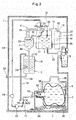
- FIG. 1 A water dispenser embodying the present invention is shown in FIG. 1 .
- This water dispenser includes: a cold water tank 2 configured to store cooled drinking water; a hot water tank 3 configured to store heated drinking water; a buffer tank 4 provided laterally of the cold water tank 2 and containing air and drinking water in upper and lower layers; a bottle basket 6 provided at a position lower than that of the cold water tank 2 and configured to receive a replaceable raw water container 5 in a position lying on its side; a mounting table 7 onto which the bottle basket 6 is placed; a cold water discharging mechanism 8; a hot water discharging mechanism 9; an air sterilization chamber 10; and a housing 1 containing therein the cold water tank 2, the hot water tank 3, the buffer tank 4, the bottle basket 6, the mounting table 7, the cold water discharging mechanism 8, the hot water discharging mechanism 9, and the air sterilization chamber 10.
- the cold water tank 2 communicates with the buffer tank 4 through an air pipe 11 and a buffer tank water supply pipe 12; communicates with the air sterilization chamber 10 through an air introduction passage 13; communicates with the raw water container 5 through a raw water pumping pipe 14; and communicates with the cold water discharging mechanism 8 through a cold water discharging pipe 15.
- the raw water pumping pipe 14 is provided with a first three-way valve 16 and a second three-way valve 17.
- the three-way valves 16 and 17 are capable of switching between first positions where a normal flow path forms and second positions where a sterilization flow path forms.
- the flow of water from the raw water container 5 to the raw water pumping pipe 14 and the flow of water from the raw water pumping pipe 14 to the cold water tank 2 are blocked to form a flow of water in a closed loop, in which water is allowed to circulate through the raw water pumping pipe 14, the first pipe for sterilization 18, the buffer tank 4, the hot water tank water supply pipe 20, the hot water tank 3 and the second pipe for sterilization 19, and back to the raw water pumping pipe 14 again, as shown in FIG. 4 to be described later.
- the three-way valves 16 and 17 are solenoid valves configured to be switched to form the sterilization flow path when energized, and to be switched to form the normal flow path when de-energized.
- Each of the first three-way valve 16 and the second three-way valve 17 shown in FIG. 1 may be replaced by a valve assembly comprising a plurality of two-way valves to achieve the same effect.
- a guide plate 21 is provided in the upper portion of the cold water tank 2.
- the guide plate 21 is formed with a slope so that the direction of the flow of drinking water supplied from the raw water pumping pipe 14 can be redirected to the horizontal direction.
- the guide plate 21 prevents the drinking water supplied into the cold water tank 2 from spreading to the entire cold water tank 2, and thus the temperature of the cold water in the lower portion of the cold water tank 2 can be maintained low.
- a water level sensor 22 is provided in the cold water tank 2, and configured to detect the water level of the drinking water contained therein. When the water level detected by the water level sensor 22 falls below a predetermined limit, a pump 23 provided in the raw water pumping pipe 14 is actuated to allow transfer of drinking water from the raw water container 5 to the cold water tank 2.
- the capacity of the cold water tank 2 is from about 2 to 4 liters.
- a diaphragm pump or a gear pump can be used as the pump 23, for example.
- the diaphragm pump the reciprocation of a diaphragm increases and decreases the volume of a pump chamber provided therein, and drinking water is allowed to be pumped up and discharged corresponding to the change in the volume of the pump chamber.
- the gear pump drinking water trapped between the tooth spaces of a pair of gears and the inner surface of the casing of the gear pump is transferred by the rotation of the gears.
- a flow rate sensor 24 is provided in the raw water pumping pipe 14, on the side of the discharge port of the pump 23.
- a cooling device 25 is provided on the outer peripheral surface of the lower portion of the cold water tank 2. The cooling device 25 is capable of cooling the drinking water in the cold water tank 2 to about 5 degrees Celsius.
- the buffer tank 4 communicates with the cold water tank 2 through the air pipe 11 and the buffer tank water supply pipe 12; communicates with the first three-way valve 16 through the first pipe 18 for sterilization, and communicates with the hot water tank 3 through the hot water tank water supply pipe 20.
- a float valve 26 is provided at the end portion of the buffer tank water supply pipe 12 on the side of the buffer tank 4. When the drinking water in the buffer tank 4 is increased to exceed a predetermined level due to the water being transferred from the cold water tank 2, the float valve 26 blocks the end portion of the buffer tank water supply pipe 12 to prevent the drinking water in the buffer tank 4 from flowing back into the cold water tank 2.
- the float valve 26 prevents this hot water from further flowing back into the cold water tank 2 through the buffer tank water supply pipe 12. Further, when the sterilization by hot water circulation to be described later is carried out, the flowing back of the hot water from the buffer tank 4 into the cold water tank 2 can also be prevented. This prevents the temperature rise of the cold water in the cold water tank 2, and the proliferation of bacteria in the cold water tank 2 associated with the temperature rise.
- the lower portion of the buffer tank 4 is formed in the shape of a cone whose diameter decreases as it gets closer to its bottom end. Therefore, the buffer tank 4 has no corners at its lower portion where drinking water tends to remain when the sterilization by hot water circulation to be described later is carried out. In general, the capacity of the buffer tank 4 is from about 0.2 to 0.5 liters.
- the hot water tank 3 communicates with the buffer tank 4 through the hot water tank water supply pipe 20; communicates with the second three-way valve 17 through the second pipe 19 for sterilization; and communicates with the hot water discharging mechanism 9 through the hot water discharging pipe 27.
- the hot water tank 3 is also connected to a drain pipe 28 through which water remaining in the hot water tank 3 is drained. Other than the time when the water remaining in the hot water tank 3 is drained, the outlet port of the drain pipe 28 is closed with a plug 29.
- a heater 30 is provided inside the hot water tank 3, and configured to heat the drinking water contained therein. The temperature of the heated drinking water is detected by a temperature sensor 31 attached to the wall of the hot water tank 3.
- the hot water tank 3 differs from the cold water tank 2 and the buffer tank 4 in that it has a structure in which the entire tank is filled with drinking water.
- the interior of the hot water tank 3 is pressurized by the weight of the drinking water contained in the buffer tank 4, which is provided at a position higher than that of the hot water tank 3, and the pressure applied to the hot water tank 3 allows for discharging of hot water contained therein through the hot water discharging mechanism 9.
- the capacity of the hot water tank 3 is from about 1 to 2 liters. While a sheathed heater is used as the heater 30 in this embodiment, an embodiment is also possible in which a band heater is wrapped around the outer periphery of hot water tank 3.
- the raw water container 5, which is received in the bottle basket 6, is provided with a water outlet port 32 in which a joint portion 33 of the raw water pumping pipe 14 is inserted in the horizontal direction.
- the joint portion 33 comprises a hollow cylindrical member through which drinking water is allowed to flow freely, and provided at a position higher than that of the pump 23, which is configured to pump up drinking water.
- a guide member 34 is provided in the vicinity of the joint portion 33.
- the rolling movement of the rollers 35 allows the bottle basket 6 in which the raw water container 5 is received to be easily settled into, and taken out of the housing 1.
- the bottle basket 6 is provided with a handle 36, and by holding the handle 36, the bottle basket 6 can be easily placed on the mounting table 7.
- the raw water container 5 used in this embodiment is a soft type container made of a thin sheet of a polyethylene terephthalate (PET) resin or polyethylene (PE) resin.
- PET polyethylene terephthalate
- PE polyethylene
- a soft type container is used as the raw water container 5 in this embodiment, it is also possible to use a rigid type container whose volume does not change even when the drinking water contained therein is pumped out, or a bag-in-box type container in which a bag made of a highly flexible resin film is placed inside a box such as a corrugated carton.
- the air sterilization chamber 10 includes a hollow casing 39 provided with an air inlet port 37 and an ozone outlet port 38; and an ozone generator 40 provided within the casing 39 and configured to convert oxygen in the air to ozone.
- the ozone outlet port 38 communicates with the cold water tank 2 through the air introduction passage 13.
- the pump 23 When the water level sensor 22 detects the fall of the water level in the cold water tank 2, as the cold water is discharged, the pump 23 is actuated to carry out the transfer of drinking water from the raw water container 5 to the cold water tank 2. By the transfer of drinking water, the water level in the cold water tank 2 rises again to recover the previous level.
- the pump 23 When the water level sensor 22 detects the fall of the water level in the cold water tank 2, as a result of water being supplied to the buffer tank 4 therefrom, the pump 23 is actuated to carry out the transfer of drinking water from the raw water container 5 to the cold water tank 2. By the transfer of drinking water, the water level in the cold water tank 2 rises again to recover the previous level.
- both the three-way valves 16 and 17 are energized, so that the first three-way valve 16 is switched to secure the flow of water from the raw water pumping pipe 14 toward the buffer tank 4, and the second three-way valve 17 is switched to secure the flow of water from the hot water tank 3 to the raw water pumping pipe 14, as shown in FIG. 4 .
- This forms the sterilization flow path which is a flow path in a closed loop, in which water is allowed to circulate through the raw water pumping pipe 14, the first pipe for sterilization 18, the buffer tank 4, the hot water tank water supply pipe 20, the hot water tank 3 and the second pipe for sterilization 19, and back to the raw water pumping pipe 14 again.
- the sterilization inside the sterilization flow path can be carried out.
- the heater 30 is actuated as necessary so that the temperature of hot water is maintained at a predetermined temperature (for example, 85 degrees Celsius) or higher, which is effective for sterilization.
- the pump 23 can be stopped as necessary. This is because, as long as hot water having a temperature of not less than the predetermined temperature is allowed to stay in the sterilization flow path, a sufficient sterilization effect can be obtained.
- the cold water tank 2 is not included in the sterilization flow path which is formed in a closed path, as described above. Therefore, there is no potential risk that cold water in the cold water tank 2 is warmed up, and it is possible to provide a user with cold water cooled to a low temperature, even while the sterilization by hot water circulation is being carried out.
- FIGs. 5 to 8 show the cold water discharging mechanism 8 of the water dispenser according to the present invention.
- the cold water discharging mechanism 8 includes: a faucet body 41 connected to the cold water discharging pipe 15; a valve body 42 made of an elastic material and provided in a cold water flow passage formed inside the faucet body 41; a faucet stem 43 configured to move the valve body 42 between open and closed positions; a faucet spring 44 biasing the faucet stem 43 in the valve closing direction; a faucet lever 45 configured to move the faucet stem 43 in the valve opening direction against the biasing force of the faucet spring 44; a locking member 46 configured to restrict the movement of the faucet stem 43 in the valve opening direction; a locking spring 47 which is a biasing member biasing the locking member 46 toward a locking position; a faucet button 48 configured to push in the locking member 46 against the biasing force of the lock spring 47 toward an unlocking position; an unlocking button 49 covering the faucet button 48
- valve body 42 When the cold water discharging mechanism 8 is in the locked state (see FIG. 5 ), the valve body 42 is in contact with a valve seat 51 provided in the flow passage formed inside the faucet body 41 by the biasing force of the faucet spring 44, and thereby blocking the discharging of cold water from a cold water outlet port 52a.
- a shaft portion 53 of the faucet stem 43 is formed with a constricted portion 54 whose diameter is smaller than that of the remaining portion of the shaft portion 53.
- the locking member 46 is provided with a through hole 55 through which the shaft portion 53 of the faucet stem 43 extends.
- the through hole 55 consists of a main hole portion 55a whose diameter is larger than that of the shaft portion 53; and an auxiliary hole portion 55b whose diameter is smaller than that of the shaft portion 53 and whose inner periphery continues to that of the main hole portion 55a.
- the constricted portion 54 is configured to engage with the auxiliary hole portion 55b having a smaller diameter than that of the main hole portion 55a, as described above, the area of engagement between the auxiliary hole portion 55b with the constricted portion 54 is increased. This allows the constricted portion 54 to be firmly engaged with the auxiliary hole portion 55b so that a secure locking function is provided.
- the auxiliary hole portion 55b does not need to be provided as long as the secure engagement of the constricted portion 54 is achieved, and an embodiment is also possible in which the constricted portion 54 is engaged with the peripheral edge of the main hole portion 55a. Further, an embodiment is also possible in which the through hole 55 is not provided in the locking member 46, and the constricted portion 54 is engaged with the peripheral edge of the locking member 46.
- the key member 50 is a member in the shape of a Japanese character " ⁇ ", and includes a base portion 56; and two engaging end portions 57a and 57b extending, respectively, from the upper and lower end portions of the base portion 56, in a horizontal direction.
- a slide knob 58 is formed at the lower end of the base portion 56, and configured to be held in order to slide the key member 50. In order to maintain the unlocked state shown in FIG.
- the key member 50 needs to be slid by holding the slide knob 58, with the lock release button 49 pressed in, so that the engaging end portions 57a and 57b of the key member 50 come into abutment with flange portions 59 formed at the unlocking button 49 which is configured to move together with the lock member 46, from the direction opposite to that of the biasing force of the lock spring 47 (see FIG. 7 ). This prevents the locking member 46 from returning to the locking position again.
- cold water can be discharged from the cold water outlet port 52a merely by operating the faucet lever 45, without unlocking the cold water discharging mechanism 8 by pressing the unlocking button 49 every time of use. This serves to significantly improve the user-friendliness of the water dispenser for users without small children, who do not require any locking mechanism.
- the slide knob 58 protrudes downward from an elongated hole formed in a decorative cover 60 provided at the front surface of the water dispenser, in a minimum length (from about several millimeters to several ten millimeter) required to be held to operate the key member 50. Since the protruded length of the slide knob 58 is restricted to the minimum level, it is possible to prevent an undesired situation in which the slide knob 58 is unexpectedly operated by a small child, or in which the slide knob 58 is mistakenly touched by a user during the cold water discharging operation, to change the locking status of the cold water discharging mechanism 8.
- an unlocking mechanism composed of a locking member 46 and a key member 50 which are identical to those in the cold water discharging mechanism 8 can be provided in the hot water discharging mechanism 9, to control the discharging of hot water from a hot water outlet port 52b.
- this unlocking mechanism in each of the cold water discharging mechanism 8 and the hot water discharging mechanism 9, it is possible to select any of the following states: a state in which the locking functions of both the cold water and hot water discharging mechanisms 8 and 9 are enabled (see FIG. 9 (a) ); a state in which the locking functions of both the cold water and hot water discharging mechanisms 8 and 9 are released (see FIG.
- the engaging end portions 57a and 57b of the key member 50 are configured to come into abutment with the flange portions 59 formed at the lock release button 49 to maintain the unlocked state.
- the key member 50 is directly engaged with the faucet button 48 or the locking member 46 configured to move together with the unlocking button 49.
- the shape of the key member 50 is not limited to the shape of " ⁇ ", and it can be changed as appropriate, as long as the function thereof to maintain the unlocked state is achieved.
- the water dispenser of the above mentioned embodiment includes three tanks: the cold water tank 2, hot water tank 3, and the buffer tank 4, the unlocking mechanism according to the present invention can be widely used in other types of water dispensers, such as one including only two tanks, namely the cold water tank 2 and the hot water tank 3, and not including the buffer tank 4.
- the raw water container 5 is placed in a position lying on its side at the lower portion of the water dispenser
- the arrangement of the raw water container 5 is not limited thereto, and the unlocking mechanism according to the present invention can be widely used in other types of water dispensers, such as one in which the raw water container 5 is placed at the upper portion of the water dispenser, or one in which the raw water container 5 is placed in a position standing on its bottom.
Landscapes
- Engineering & Computer Science (AREA)
- Mechanical Engineering (AREA)
- General Engineering & Computer Science (AREA)
- Devices For Dispensing Beverages (AREA)
Applications Claiming Priority (2)
| Application Number | Priority Date | Filing Date | Title |
|---|---|---|---|
| JP2013039212A JP5529309B1 (ja) | 2013-02-28 | 2013-02-28 | ウォーターサーバー |
| PCT/JP2013/081928 WO2014132507A1 (ja) | 2013-02-28 | 2013-11-27 | ウォーターサーバー |
Publications (2)
| Publication Number | Publication Date |
|---|---|
| EP2962983A1 true EP2962983A1 (de) | 2016-01-06 |
| EP2962983A4 EP2962983A4 (de) | 2016-06-08 |
Family
ID=51175797
Family Applications (1)
| Application Number | Title | Priority Date | Filing Date |
|---|---|---|---|
| EP13876672.0A Withdrawn EP2962983A4 (de) | 2013-02-28 | 2013-11-27 | Wasserservierer |
Country Status (7)
| Country | Link |
|---|---|
| US (1) | US20160009541A1 (de) |
| EP (1) | EP2962983A4 (de) |
| JP (1) | JP5529309B1 (de) |
| KR (1) | KR102179359B1 (de) |
| CN (1) | CN105008266B (de) |
| TW (1) | TWI592359B (de) |
| WO (1) | WO2014132507A1 (de) |
Families Citing this family (11)
| Publication number | Priority date | Publication date | Assignee | Title |
|---|---|---|---|---|
| JP5529314B1 (ja) * | 2013-03-07 | 2014-06-25 | 株式会社コスモライフ | ウォーターサーバー |
| JP2016113173A (ja) * | 2014-12-15 | 2016-06-23 | 株式会社ジャパンボトルドウォーター | 飲料サーバー |
| KR101674094B1 (ko) * | 2015-10-02 | 2016-11-09 | (주)원봉 | 냉온수기 |
| JP6005240B1 (ja) | 2015-10-14 | 2016-10-12 | 株式会社コスモライフ | 鍵付きウォーターサーバー |
| JP6815193B2 (ja) | 2016-12-27 | 2021-01-20 | 株式会社コスモライフ | 鍵付きウォーターサーバー |
| JP6814052B2 (ja) * | 2017-01-18 | 2021-01-13 | 株式会社コスモライフ | ウォーターサーバー |
| US10845117B2 (en) * | 2018-12-10 | 2020-11-24 | Midea Group Co., Ltd. | Refrigerator with variable fluid dispenser |
| US11009278B2 (en) | 2018-12-10 | 2021-05-18 | Midea Group Co., Ltd. | Refrigerator with variable ice dispenser |
| US11800890B2 (en) | 2020-03-02 | 2023-10-31 | Sorting Robotics, Inc. | Automated deposition of highly viscous fluids into thin-walled cylinders |
| CN111692415B (zh) * | 2020-07-23 | 2024-11-22 | 安徽省富光实业股份有限公司 | 防烫吸管重力球阀及水杯、水壶 |
| CN111839230A (zh) * | 2020-08-26 | 2020-10-30 | 小熊电器股份有限公司 | 一种即冷即热饮水装置及即冷即热控制方法 |
Family Cites Families (17)
| Publication number | Priority date | Publication date | Assignee | Title |
|---|---|---|---|---|
| JPH11248029A (ja) * | 1998-03-04 | 1999-09-14 | Kvk Corp | 給水栓ハンドルのロック機構 |
| AUPQ270399A0 (en) * | 1999-09-08 | 1999-09-30 | Australian Dynamic Products Pty. Ltd. | Tap |
| CN2451829Y (zh) * | 2000-11-13 | 2001-10-03 | 于乔治 | 安全水龙头 |
| US20030001124A1 (en) * | 2001-07-02 | 2003-01-02 | Chih-Hsien Chen | Safety device of water faucet |
| JP3683214B2 (ja) * | 2001-12-20 | 2005-08-17 | オルゴ株式会社 | 液体容器 |
| WO2004110921A1 (en) * | 2003-06-12 | 2004-12-23 | Byung-Tae Chae | Beverage dispensing valve |
| JP2005249266A (ja) * | 2004-03-03 | 2005-09-15 | Fuji Electric Retail Systems Co Ltd | 飲料水のディスペンサ |
| BRPI0614897A2 (pt) * | 2005-08-05 | 2011-04-19 | Johnson Diversey Inc | aparelho de distribuição |
| JP2009150453A (ja) * | 2007-12-19 | 2009-07-09 | Deto Co Ltd | 吐出コック |
| KR100896798B1 (ko) * | 2008-05-21 | 2009-05-12 | 우미화 | 정수기용 이중 안전 코크 |
| WO2010107701A1 (en) * | 2009-03-16 | 2010-09-23 | The Meyer Company | Faucet with locking safety handle |
| US8191741B2 (en) * | 2009-03-31 | 2012-06-05 | George Yui | Water dispenser faucet actuators |
| US20100252585A1 (en) * | 2009-04-01 | 2010-10-07 | Yui George M | Water probe for bottom loading water cooler |
| JP5388186B2 (ja) * | 2009-04-10 | 2014-01-15 | 恒久 千葉 | 飲料水供給装置 |
| CN102401181B (zh) * | 2010-09-14 | 2015-06-10 | 珠海格力电器股份有限公司 | 防烫水龙头及饮水机 |
| JP5598445B2 (ja) * | 2011-08-04 | 2014-10-01 | 静夫 大垣内 | 混合吐水栓 |
| US9422145B2 (en) * | 2013-11-05 | 2016-08-23 | Mtn Products, Inc. | Child safety faucet |
-
2013
- 2013-02-28 JP JP2013039212A patent/JP5529309B1/ja active Active
- 2013-11-27 CN CN201380073841.9A patent/CN105008266B/zh active Active
- 2013-11-27 EP EP13876672.0A patent/EP2962983A4/de not_active Withdrawn
- 2013-11-27 WO PCT/JP2013/081928 patent/WO2014132507A1/ja not_active Ceased
- 2013-11-27 KR KR1020157026259A patent/KR102179359B1/ko active Active
- 2013-11-27 US US14/769,138 patent/US20160009541A1/en not_active Abandoned
- 2013-12-20 TW TW102147619A patent/TWI592359B/zh active
Also Published As
| Publication number | Publication date |
|---|---|
| CN105008266A (zh) | 2015-10-28 |
| TW201433538A (zh) | 2014-09-01 |
| TWI592359B (zh) | 2017-07-21 |
| WO2014132507A1 (ja) | 2014-09-04 |
| US20160009541A1 (en) | 2016-01-14 |
| JP5529309B1 (ja) | 2014-06-25 |
| KR20150122206A (ko) | 2015-10-30 |
| EP2962983A4 (de) | 2016-06-08 |
| KR102179359B1 (ko) | 2020-11-16 |
| CN105008266B (zh) | 2017-05-31 |
| JP2014166862A (ja) | 2014-09-11 |
Similar Documents
| Publication | Publication Date | Title |
|---|---|---|
| EP2962983A1 (de) | Wasserservierer | |
| EP2980013A1 (de) | Wasserservierer | |
| US9440840B2 (en) | Water dispenser | |
| US7974527B1 (en) | Hot liquid dispenser | |
| JP2009526189A (ja) | 流体用の滴下防止分配弁 | |
| CN105050937B (zh) | 饮水机 | |
| CN104736467A (zh) | 饮水机 | |
| CN113876203A (zh) | 盒抽取单元 | |
| EP2962982A1 (de) | Wasserservierer | |
| JP2010247838A (ja) | 飲料水供給装置 | |
| CN1956915B (zh) | 带有流量限制的小桶龙头适配器 | |
| CN108137308B (zh) | 带有钥匙的饮水机 | |
| JP2017074989A (ja) | 鍵付きウォーターサーバー | |
| KR101623789B1 (ko) | 정수기 | |
| JP2013230826A (ja) | ウォータディスペンサ | |
| JP2014008980A (ja) | 水パックからの飲料水を下方の冷水タンクと温水タンクに重力により導入する給水機 | |
| JP7060259B2 (ja) | 誘導的に加熱可能な流体貯蔵器 | |
| CN108236373B (zh) | 带钥匙的饮水机 | |
| TWM487413U (zh) | 具紅外線感測功能之自動飲水機 | |
| JP5538482B2 (ja) | プラスチックフィルム製の袋に飲料水を封入した水袋を用いる給水機 | |
| KR101654065B1 (ko) | 정수기 | |
| JP2017081600A (ja) | 飲料ディスペンサ |
Legal Events
| Date | Code | Title | Description |
|---|---|---|---|
| PUAI | Public reference made under article 153(3) epc to a published international application that has entered the european phase |
Free format text: ORIGINAL CODE: 0009012 |
|
| 17P | Request for examination filed |
Effective date: 20150928 |
|
| AK | Designated contracting states |
Kind code of ref document: A1 Designated state(s): AL AT BE BG CH CY CZ DE DK EE ES FI FR GB GR HR HU IE IS IT LI LT LU LV MC MK MT NL NO PL PT RO RS SE SI SK SM TR |
|
| AX | Request for extension of the european patent |
Extension state: BA ME |
|
| DAX | Request for extension of the european patent (deleted) | ||
| A4 | Supplementary search report drawn up and despatched |
Effective date: 20160506 |
|
| RIC1 | Information provided on ipc code assigned before grant |
Ipc: B67D 3/04 20060101ALI20160429BHEP Ipc: B67D 1/08 20060101ALI20160429BHEP Ipc: B67D 3/00 20060101ALI20160429BHEP Ipc: B67D 1/14 20060101AFI20160429BHEP |
|
| STAA | Information on the status of an ep patent application or granted ep patent |
Free format text: STATUS: THE APPLICATION HAS BEEN WITHDRAWN |
|
| 18W | Application withdrawn |
Effective date: 20160906 |