EP2962814A2 - Robotersimulator und Dateierzeugungsverfahren für Robotersimulator - Google Patents
Robotersimulator und Dateierzeugungsverfahren für Robotersimulator Download PDFInfo
- Publication number
- EP2962814A2 EP2962814A2 EP14200583.4A EP14200583A EP2962814A2 EP 2962814 A2 EP2962814 A2 EP 2962814A2 EP 14200583 A EP14200583 A EP 14200583A EP 2962814 A2 EP2962814 A2 EP 2962814A2
- Authority
- EP
- European Patent Office
- Prior art keywords
- robot
- information
- output
- job
- dimensional images
- Prior art date
- Legal status (The legal status is an assumption and is not a legal conclusion. Google has not performed a legal analysis and makes no representation as to the accuracy of the status listed.)
- Withdrawn
Links
Images





Classifications
-
- B—PERFORMING OPERATIONS; TRANSPORTING
- B25—HAND TOOLS; PORTABLE POWER-DRIVEN TOOLS; MANIPULATORS
- B25J—MANIPULATORS; CHAMBERS PROVIDED WITH MANIPULATION DEVICES
- B25J9/00—Program-controlled manipulators
- B25J9/16—Program controls
- B25J9/1656—Program controls characterised by programming, planning systems for manipulators
- B25J9/1671—Program controls characterised by programming, planning systems for manipulators characterised by simulation, either to verify existing program or to create and verify new program, CAD/CAM oriented, graphic oriented programming systems
-
- G—PHYSICS
- G06—COMPUTING OR CALCULATING; COUNTING
- G06F—ELECTRIC DIGITAL DATA PROCESSING
- G06F30/00—Computer-aided design [CAD]
- G06F30/20—Design optimisation, verification or simulation
-
- B—PERFORMING OPERATIONS; TRANSPORTING
- B25—HAND TOOLS; PORTABLE POWER-DRIVEN TOOLS; MANIPULATORS
- B25J—MANIPULATORS; CHAMBERS PROVIDED WITH MANIPULATION DEVICES
- B25J9/00—Program-controlled manipulators
- B25J9/16—Program controls
- B25J9/1602—Program controls characterised by the control system, structure, architecture
- B25J9/1605—Simulation of manipulator lay-out, design, modelling of manipulator
-
- G—PHYSICS
- G05—CONTROLLING; REGULATING
- G05B—CONTROL OR REGULATING SYSTEMS IN GENERAL; FUNCTIONAL ELEMENTS OF SUCH SYSTEMS; MONITORING OR TESTING ARRANGEMENTS FOR SUCH SYSTEMS OR ELEMENTS
- G05B19/00—Program-control systems
- G05B19/02—Program-control systems electric
- G05B19/42—Recording and playback systems, i.e. in which the program is recorded from a cycle of operations, e.g. the cycle of operations being manually controlled, after which this record is played back on the same machine
Definitions
- the embodiment discussed herein is directed to a robot simulator and a file generation method for the robot simulator.
- control simulation system disclosed in Japanese Patent Application Laid-open No. 2008-100315 creates an animation to simulate motion of a robot and various instruments so as to replay the animation.
- An operator uses such a system, and thus can verify the time required for a robot's operation and the interference of a robot with the periphery without actually actuating the robot.
- the conventional technique has required a simulator and a teaching system even for confirming the simulation results.
- This has limited partner apparatuses capable of confirming and receiving the created simulation results.
- an aspect of the embodiment provides a robot simulator capable of easily confirming and distributing simulation results and a file generation method for the robot simulator.
- a robot simulator includes a job information acquiring unit, an image generating unit, a playback information generating unit, and an output unit.
- the job information acquiring unit acquires job information that includes a group of operation commands for a robot and information for a plurality of target points through which the robot passes.
- the image generating unit generates virtual three-dimensional images of a robot system including the robot in a three-dimensional space for each of the operation commands.
- the playback information generating unit generates playback information for continuously replaying the three-dimensional images by animation in association with the job information.
- the output unit generates and outputs an output file in which the job information, the three-dimensional images, and the playback information are embedded in an electronic document format that is browsable in a general-purpose manner.
- the simulation results can be easily confirmed and distributed.
- the following describes a robot simulator that outputs a graphic image for a three-dimensional model of a robot to a display unit such as a display as an example.
- the graphic image for such a three-dimensional model may be hereinafter referred to as a "virtual image”.
- FIG. 1 is a schematic diagram illustrating the whole configuration of a robot system 1 including a robot simulator 10 in accordance with the embodiment.
- the robot system 1 includes the robot simulator 10, a robot controller 20, and a robot 30 as illustrated in FIG. 1 .
- the robot simulator 10 includes a simulator controller 11, a display unit 12, an operation unit 13, and a job information database (DB) 14.
- DB job information database
- the simulator controller 11 is a controller for controlling the whole robot simulator 10, and includes a calculation processor and a storage apparatus.
- the simulator controller 11 is connected to various apparatuses forming the robot simulator 10 such as the display unit 12, the operation unit 13, and the job information DB 14 so as to transmit information to each other.
- the simulator controller 11 also outputs a virtual image including the robot 30 whose operation has been simulated and calculated to the display unit 12 based on the operation of an operator through the operation unit 13.
- the simulator controller 11 generates a job program, which is a group of operation commands for operating the robot 30, from the virtual image based on the operation of an operator through the operation unit 13, and registers the generated job program on the job information DB 14.
- the display unit 12 is a display device such as what is called a display.
- the operation unit 13 is a pointing device such as a mouse.
- the operation unit 13 is not necessarily formed as a hardware component and, for example, may be a software component such as touch keys displayed on a touch panel display.
- the job information DB 14 is a database where job information, which is the information related to teaching such as the above-mentioned job program and "teaching points" included in the job program, is registered.
- the “teaching points” are information serving as target positions (target points) through which each joint or rotation mechanism of the robot must pass at the time of replaying the operation of the robot 30, and are, for example, stored as pulse values of each encoder provided to a servomotor driving each axis of the robot 30.
- the robot 30 operates based on the information of a plurality of teaching points, and the teaching points are, therefore, associated and stored in the job information DB 14 for each motion (job) of the robot 30.
- the job program of the robot 30 includes combined information such as the teaching points, interpolation operation commands between each teaching point, and operation commands for an end effector installed on the tip part of the robot 30.
- the job information DB 14 stores therein information of the teaching points included in the job program of the robot 30 for each job program. For example, the robot 30 is operated based on the job program at the time of replaying the operation of the robot 30.
- the job information DB 14 is connected to the robot controller 20, which is a controller for controlling the real operation of the robot 30, so as to transmit information to each other.
- the robot controller 20 controls various operations of the robot 30 based on the job program registered on the job information DB 14.
- the job information DB 14 (robot simulator 10) and the robot controller 20 are connected to each other. If the job program generated by the robot simulator 10 is configured to be stored in a predetermined storage unit (not illustrated) in the robot controller 20, the job information DB 14 (robot simulator 10) and the robot controller 20 are not necessarily connected to each other.
- the medium may be connected to the robot controller 20 and stored in a predetermined storage unit (not illustrated) in the robot controller 20 by a predetermined operation.
- a predetermined storage unit not illustrated
- FIG. 1 illustrates an example of the configuration where the job information DB 14 and the simulator controller 11 are separately formed, but the job information DB 14 may be stored in a storage unit inside the simulator controller 11.
- the robot 30 includes a base unit 31, a first arm 32, a second arm 33, a wrist unit 34, and an end effector 35.
- the base unit 31 is fixed to a floor surface, etc., and supports the base end part of the first arm 32 so as to rotate the base end part of the first arm 32 around the axis S (see an arrow 101 in FIG. 1 ) and around the axis L (see an arrow 102 in FIG. 1 ).
- the first arm 32 has its base end part supported by the base unit 31 as described above and supports the base end part of the second arm 33 at its tip part so as to rotate the base end part of the second arm 33 around the axis U (see an arrow 103 in FIG. 1 ).
- the second arm 33 has its base end part supported by the first arm 32 as described above and supports the base end part of the wrist unit 34 at its tip part so as to rotate the base end part of the wrist unit 34 around the axis B (see an arrow 105 in FIG. 1 ).
- the second arm 33 is provided so as to be rotated around the axis R (see an arrow 104 in FIG. 1 ).
- the wrist unit 34 has its base end part supported by the second arm 33 as described above and supports the base end part of the end effector 35 at its tip part so as to rotate the base end part of the end effector 35 around the axis T (see an arrow 106 in FIG. 1 ).
- the end effector 35 is a welding torch
- the robot 30 is a welding robot that uses the welding torch to apply welding to a workpiece W with a T-shaped cross section placed on a placement base 41.
- a drive source such as a servomotor is mounted on each joint of the robot 30, and these drive sources are driven by control of the robot controller 20 based on the job program registered on the job information DB 14.
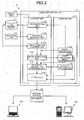
- FIG. 2 is a block diagram illustrating the configuration of the robot simulator 10 in accordance with the embodiment.
- FIG. 2 illustrates only the components necessary for the explanation of the robot simulator 10, and omits the description about the general components.
- FIG. 2 mainly illustrates the internal configuration of the simulator controller 11, and may simplify the explanation of the display unit 12, the operation unit 13, and the job information DB 14, which have been already illustrated in FIG. 1 .
- the simulator controller 11 includes a control unit 111 and a storage unit 112 as illustrated in FIG. 2 .
- the control unit 111 includes an operation receiving unit 111a, a job generating unit 111b, a job information acquiring unit 111c, an image generating unit 111d, a playback information generating unit 111e, and an output unit 111f.
- the storage unit 112 stores therein model information 112a, three-dimensional images 112b, and playback information 112c.
- the operation receiving unit 111a receives input operation input by an operator through the operation unit 13, and notifies the job generating unit 111b of the received input operation related to job generation and job editing.
- Examples of the input operation related to job generation and job editing include operation for handling operation components such as a "GENERATE JOB” button and an “EDIT JOB” button displayed on the display unit 12.
- the operation receiving unit 111a also notifies the job information acquiring unit 111c of the received input operation related to the output of a "general-purpose electronic document".
- the "general-purpose electronic document” means a file in an electronic document format that can be browsed in a general-purpose manner. Examples of the electronic document formats that can be browsed in a general-purpose manner include a portable document format (PDF) (registered trademark).
- PDF portable document format
- this embodiment allows the simulation results of the robot simulator 10 to be output in a "general-purpose electronic document". This enables the simulation results to be confirmed and distributed without limiting partner apparatuses.
- Examples of the above-mentioned input operation related to the output of a "general-purpose electronic document” include operation for clicking an operation component such as an "OUTPUT FOR GENERAL-PURPOSE” button displayed on the display unit 12.
- FIG. 3 is a schematic diagram illustrating an example of the displayed contents displayed on the display unit 12.
- a virtual image of a robot system 1V including the robot 30V, a placement base 41V, and a workpiece WV is displayed on a display window 120, which is one of the display areas in the display unit 12.
- GUI graphical user interface
- the button 122a corresponds to the above-mentioned “GENERATE JOB” button.
- the buttons 122b and 122c correspond to the above-mentioned “EDIT JOB” button.
- the button 122d corresponds to the above-mentioned “OUTPUT FOR GENERAL-PURPOSE” button.
- An orthogonal coordinate system is displayed in the lower left of the virtual image area 121.
- This is a reference coordinate system in a virtual image, corresponds to a three-dimensional coordinate system, and serves as the reference in the horizontal direction and the vertical direction.
- a direction parallel to the XY plane specified by the X axis and Y axis of the reference coordinate system is defined as the horizontal direction
- a direction parallel to the Z axis of the reference coordinate system is defined as the vertical direction.
- An operator operates such GUI widgets and operable components on a virtual image (for example, each part of the robot 30V) so as to instruct the robot simulator 10 to operate.
- the robot simulator 10 can drive each joint of the robot 30V, change a viewpoint to display a virtual image seen from a certain direction, and enlarge/reduce the display based on the operation instructed by the operator.
- Each joint position of the robot 30 where the tip of the end effector 35 (the tip of the welding torch in this embodiment) may reach a specific point in a virtual image is obtained using the inverse kinematics computation so as to generate and display the robot 30V where the tip of the end effector 35 has reached the specific point.
- Examples of the processes for generating a job by the robot simulator 10 include a process where an operator clicks a "GENERATE JOB" button, a dialogue box (not illustrated) urging the operator to input conditions necessary for generating a job is displayed on the display unit 12, and then a job program is automatically generated and registered on the job information DB 14 depending on the conditions input by the operator.
- the operation instructed by an operator enables the teaching points and the job programs registered on the job information DB 14 to be read out, enables the robot 30V having reached a specific teaching point to be displayed, enables a series of operations of the robot 30 due to a job program to be reproduced on the display unit 12, and enables the contents of the job program to be changed.
- the contents of the job program can be displayed as "JOB CONTENTS" in the dialogue box 123, for example, as illustrated in FIG. 3 .
- the job generating unit 111b When having received the input operation related to the job generation and job editing from the operation receiving unit 111a, the job generating unit 111b reflects the contents of the input operation on a virtual image displayed on the display unit 12, and generates a job program based on the contents of the input operation so as to register the generated job program on the job information DB 14.
- the model information 112a is information that includes rendering information previously defined for each kind of the robot 30 and the workpiece W.
- An operator can perform input related to the output of the "general-purpose electronic document" on the generated job program. Specifically, this corresponds to the above-mentioned operation for clicking an "OUTPUT FOR GENERAL-PURPOSE" button.
- the job information acquiring unit 111c acquires job information, which is information including a job program registered on the job information DB 14.
- the job information acquiring unit 111c also transmits the acquired job information to the image generating unit 111d.
- the job information acquiring unit 111c acquires job information from the job information DB 14 where job programs and the like have been registered by the job generating unit 111b, but this is not limiting.
- job information generated by a computer or other apparatuses different from the simulator controller 11 may be acquired via a communication network, or may be acquired via media such as a USB memory.
- the image generating unit 111d generates a virtual three-dimensional image of the robot system 1 including the robot 30 in the three-dimensional space based on the job information received from the job information acquiring unit 111c and the model information 112a, and stores the generated three-dimensional image as the three-dimensional images 112b in the storage unit 112.
- the three-dimensional images 112b is generated at least for each job step of the job program (which corresponds to each operation command).
- the image generating unit 111d also transmits the job information received from the job information acquiring unit 111c to the playback information generating unit 111e.
- the playback information generating unit 111e generates, based on the job information received from the image generating unit 111d and the three-dimensional images 112b, information for continuously replaying the three-dimensional images 112b by animation in association with the job information, and stores the generated information as the playback information 112c in the storage unit 112.
- Examples of the playback information 112c include information for associating the three-dimensional images 112b for each job step, information related to the playback order of the three-dimensional images 112b, information related to the interpolation between the three-dimensional images 112b, and information related to the playback time for each frame at the time of continuously replaying the three-dimensional images 112b by animation.
- the playback information generating unit 111e can synchronize the playback time with the real operating time, which is the time when the robot 30 really operates, and then set the playback time.
- the playback information generating unit 111e also transmits the job information received from the image generating unit 111d to the output unit 111f.
- the output unit 111f generates and outputs, based on the job information received from the playback information generating unit 111e, the three-dimensional images 112b, and the playback information 112c, a general-purpose electronic document G where these pieces of information are embedded as an output file.
- the output unit 111f can embed additional information related to the job program and the general-purpose electronic document G at the time of generating the general-purpose electronic document G.
- Examples of the concrete processes include a process where an operator clicks an "OUTPUT FOR GENERAL-PURPOSE" button, a dialogue box (not illustrated) urging the operator to input additional information is displayed on the display unit 12, and then the output unit 111f embeds the additional information such as a text input by and a still image specified by the operator at the time of generating the general-purpose electronic document G.
- the output unit 111f can embed the job information, the three-dimensional images 112b, and the playback information 112c using an application programming interface (API) of Java (registered trademark).
- API application programming interface
- the general-purpose electronic document G includes these pieces of information as a part of the PDF file.
- the general-purpose electronic document G includes the job information, the three-dimensional images 112b, and the playback information 112c. This enables the three-dimensional images 112b to be continuously replayed by animation on the personal computers 201 and 202.
- the simulation results by the robot simulator 10 can be easily confirmed or distributed even in the environment where no robot simulator 10 is introduced.
- This can bring advantages that could not have been provided by the conventional technique, for example, an advantage where a person in charge of sales can carry the general-purpose electronic document G in a medium such as a USB memory to a client and perform business activities while allowing the client to confirm the general-purpose electronic document G.
- the storage unit 112 is a storage device such as a hard disk drive and nonvolatile memory, and stores therein the model information 112a, the three-dimensional images 112b, and the playback information 112c.
- the contents of the model information 112a, the three-dimensional images 112b, and the playback information 112c have been already described, and the description thereof will be omitted.
- FIG. 2 illustrates an example where the simulator controller 11 generates a virtual image of the robot 30V, etc., based on the preregistered model information 112a, but the information necessary for generating an image may be sequentially acquired from a higher-level apparatus communicably connected to the simulator controller 11.
- FIG. 4 is a view illustrating an example of the output layouts of the general-purpose electronic document G.
- FIG. 4 to FIG. 5K illustrate cases where the general-purpose electronic document G is displayed, for example, on the display unit 12 of the robot simulator 10 and display apparatuses such as displays of the personal computers 201 and 202 by the application software for browsing preliminary installed in the robot simulator 10 and the personal computers 201 and 202.
- the general-purpose electronic document G is output by the output unit 111f in an output layout where a plurality of output areas G1 to G8 and a plurality of operation components G10 to G16 are arranged, for example.
- the output area G1 is a "view area”, and is an area where a virtual three-dimensional image of the robot system 1V including the robot 30V, a robot controller 20V, the placement base 41V, the workpiece WV, and the above-mentioned reference coordinate system (see FIG. 3 ) in the three-dimensional space is output.
- the output area G2 is a "client name area” where a client name is output
- the output area G3 is a "title area” where a title name of the general-purpose electronic document G is output.
- the output area G4 is a "job name area” where a job name confirmable in the general-purpose electronic document G is output
- the output area G5 is an "information area” where the information related to the job program and the general-purpose electronic document G is output such as a model of the robot 30V, a date when the general-purpose electronic document G is output, and a name of an operator.
- the information output to the output areas G2 to G5 is based on the above-mentioned additional information.
- the output area G6 is a "command area" where the contents of the job information, specifically the whole job steps of the job program are sorted and output in the execution order.
- the job steps in the "command area” can be optionally selected in the unit of rows by pointing devices such as a mouse.
- the output area G7 is a "detailed area" where detailed information of the selected job step is output.
- the output area G8 is a "cycle time area" where the playback time is output when the robot system 1V in the output area G1 has been replayed by animation.
- the playback time can be synchronized with the real operating time of the robot 30 as described above.
- the operation component G10 is a "Play (&Pause)" button for switching the animation playback and stop of the robot system 1V for each click.
- the operation component G11 is a "Reset” button for returning the start point of the animation playback to the first job step.
- the operation component G12 is a "Repeat" check box for repeatedly replaying animation of the robot system 1V for each check.
- Each of the operation components G13 to G16 is a button for changing the viewpoint of the robot system 1V in the output area G1 to a predetermined direction and position.
- the "Default" button of the operation component G13 is clicked for changing the viewpoint of the robot system 1V to a predetermined position in an oblique direction.
- the "Top” button of the operation component G14 is clicked for changing the same viewpoint to a plane view.
- the "Side” button of the operation component G15 is clicked for changing the same viewpoint to what is called a side view.
- the "Front" button of the operation component G16 is clicked for changing the same viewpoint to what is called a front view.
- Specific images of changes in viewpoints will be described with reference to FIGS. 5E , 5F , and 5I to 5K .
- the display unit 12 and the operation unit 13 of the robot simulator 10 are used for preliminary performing various settings such as the arrangement of the output areas G1 to G8 and the operation components G10 to G16, the definition of the output contents, and the allocation of functions.
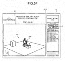
- FIGS. 5A to 5G and FIGS. 5I to 5K are views (No. 1) to (No. 10) illustrating specific examples of the general-purpose electronic document G.
- FIG. 5H is a view illustrating an example of the operation on the general-purpose electronic document G.
- a cycle time is output in the form of "Cycle Time (sec): XX.XX" to the output area G8.
- the cycle time is updated as appropriate depending on the animation playback in the output area G1.
- the posture of the robot 30V illustrated in the output area G1 in FIG. 4 may be hereinafter referred to as a "basic posture".
- a “basic posture” corresponds to an initial state posture before the job program in the output area G6 is executed.
- the robot 30V in the output area G1 is updated in a still image so as to be in a state where the job step has been executed by the real robot 30.
- the robot 30V in the output area G1 is changed to the robot 30V having taken a reached posture to the teaching point depending on the selected job step based on the playback information 112c so as to jump from a still image to a still image.
- FIG. 5A illustrates a state in which the robot 30V has been updated in a still image to the reached posture where the job step has been executed.
- "MOVL” is an interpolation operation command including the specification of the interpolating method for the robot 30V. Specifically, “MOVL” is a command for operating the robot 30V so that the moving locus of the end effector 35 depicts a straight line.
- "C00002" denotes a teaching point that the robot 30V must reach.
- FIG. 5A illustrates a state where the robot 30V has reached the teaching point C00002.
- FIG. 5B illustrates a state in which the robot 30V has been updated in a still image to the reached posture where the job step has been executed. Similarly to FIG. 5A , FIG. 5B illustrates a state where the robot 30V has reached a teaching point C00003.
- FIG. 5C illustrates a state in which the robot 30V has been updated in a still image to the reached posture where the job step has been executed. Specifically, in FIG. 5C , the robot 30V takes the reached posture where the tip of the welding torch comes to the back side of the workpiece WV with a T-shaped cross section. FIG. 5C illustrates a state where the robot 30V has reached a teaching point C00006.
- FIG. 5D illustrates a state in which the robot 30V has been updated in a still image to the reached posture where the job step has been executed.
- FIG. 5D illustrates a state where the robot 30V has reached a teaching point C00007.
- selecting the job step causes the robot 30V to be updated to the reached posture where the selected job step has been executed, and then, clicking the "Play" button causes the animation where a further job program is executed to be replayed.
- Such animation playback may start from, for example, the job step as its reference or may start from a teaching point just before the teaching point corresponding to the job step as its reference.
- the robot simulator 10 in accordance with the embodiment enables a series of operations of the robot 30V at the time of executing the job program to be confirmed and verified with the use of animation playback. Furthermore, the robot simulator 10 enables the position and posture of the robot 30V including the end effector 35 at the teaching point depending on the selected job step to be confirmed and verified.
- FIG. 5D illustrates a state where the tip of the welding torch in the robot 30V is hidden on the back side of the workpiece WV.
- the viewpoint position in the output area G1 can be optionally rotated and changed in the general-purpose electronic document G by dragging the mouse cursor C in an arc shape on the output area G1 while pressing the mouse button (see an arrow 505 in FIG. 5E ).
- the part hidden from a certain viewpoint can be exposed and can be easily confirmed by a viewer.
- the operation components G13 to G16 are used for changing the viewpoint in the output area G1 to a predetermined direction and position.
- the viewpoint of the robot system 1V in the output area G1 is based on the intermediate direction between the X-axis positive direction and the Y-axis negative direction in the reference coordinate system in FIG. 5F and on a predetermined position.
- a predetermined operation associated on the output area G1 is performed so as to change the scale in the general-purpose electronic document G.
- FIG. 5G illustrates a state where the robot 30V is enlarged in the output area G1 by changing the scale from a predetermined position in FIG. 5F .
- the scale can be changed by, for example, placing the mouse cursor C on the output area G1 and then rotating a mouse wheel 13a of the mouse serving as the operation unit 13 for a certain amount as illustrated in FIG. 5H (see an arrow 506 in FIG. 5H ).
- the scale change can optimize the distance and enable a viewer to easily confirm the distance in the general-purpose electronic document G.
- the viewpoint change describes a case where the "Top" button of the operation component G14 is operated.
- the viewpoint of the robot system 1V in the output area G1 is based on a predetermined position in the Z-axis positive direction in FIG. 5I .
- FIG. 6 is a flowchart illustrating the process for the processing executed by the robot simulator 10.
- the job information corresponding to the simulation results has been generated by the job generating unit 111b and has been registered on the job information DB 14.
- the job information acquiring unit 111c acquires job information from the job information DB 14 (Step S101).
- the image generating unit 111d generates the three-dimensional images 112b of the robot system 1 for each operation command included in the job information (Step S102).
- the playback information generating unit 111e generates the playback information 112c for replaying the three-dimensional images 112b by animation in association with the job information (Step S103).
- the output unit 111f generates and outputs the output file "general-purpose electronic document G" where the job information, the three-dimensional images 112b, and the playback information 112c are embedded in a general-purpose electronic document format (Step S104) and then ends the processing.
- the robot simulator in accordance with the embodiment includes the job information acquiring unit, the image generating unit, the playback information generating unit, and the output unit.
- the job information acquiring unit acquires job information that is a group of operation commands to a robot and that is information including a plurality of target points through which the robot must pass.
- the image generating unit generates a virtual three-dimensional image of the robot system including the robot in the three-dimensional space for each operation command.
- the playback information generating unit generates playback information that is information for continuously replaying the above-mentioned three-dimensional images by animation in association with the above-mentioned job information.
- the output unit generates and outputs an output file where the above-mentioned job information, the above-mentioned three-dimensional image, and the above-mentioned playback information are embedded in an electronic document format that can be browsed in a general-purpose manner.
- the robot simulator in accordance with the embodiment enables the simulation results to be easily confirmed and distributed.
- the above-mentioned embodiment has described a robot simulator that can acquire the simulation results as the job information and output this job information in a general-purpose electronic document format in association with a virtual three-dimensional image of the robot system in the three-dimensional space as an example.
- Such a robot simulator can be formed as a teaching system if the robot simulator has a function of generating the job information.
- the robot simulator in accordance with the above-mentioned embodiment includes the job generating unit, and can be converted into a teaching system.
- simulator controller has functions of generating the job program and outputting the general-purpose electronic document as an example, but simulator controllers may be separately formed for these functions.
- a new output area which can be said as an optionally editable "free area”
- a new output area be provided so as to output information such as information related to the weight of the end effector, dynamic information related to the position of the tip required to reach the teaching point, and information related to each axis included in the end effector to the "free area”.
- the items output to each area may be changed as appropriate. For example, "my company name” can be output to the "client name area”.
- the above-mentioned embodiment has described a case where the robot is a welding robot that applies welding to a workpiece as an example, but this does not limit the use of the robot.
- the above-mentioned embodiment has described a case where a mouse is mainly used for operation as an example, but this is not limiting.
- the general-purpose electronic document may be displayed on what is called a multi-touch compatible touch panel so as to receive the multi-touch operation of a viewer on the touch panel.
Landscapes
- Engineering & Computer Science (AREA)
- Robotics (AREA)
- Mechanical Engineering (AREA)
- Automation & Control Theory (AREA)
- Physics & Mathematics (AREA)
- General Physics & Mathematics (AREA)
- Theoretical Computer Science (AREA)
- Evolutionary Computation (AREA)
- Geometry (AREA)
- General Engineering & Computer Science (AREA)
- Computer Hardware Design (AREA)
- Manipulator (AREA)
- Processing Or Creating Images (AREA)
- Numerical Control (AREA)
Applications Claiming Priority (1)
| Application Number | Priority Date | Filing Date | Title |
|---|---|---|---|
| JP2014135205A JP6350037B2 (ja) | 2014-06-30 | 2014-06-30 | ロボットシミュレータおよびロボットシミュレータのファイル生成方法 |
Publications (2)
| Publication Number | Publication Date |
|---|---|
| EP2962814A2 true EP2962814A2 (de) | 2016-01-06 |
| EP2962814A3 EP2962814A3 (de) | 2016-08-10 |
Family
ID=52345003
Family Applications (1)
| Application Number | Title | Priority Date | Filing Date |
|---|---|---|---|
| EP14200583.4A Withdrawn EP2962814A3 (de) | 2014-06-30 | 2014-12-30 | Robotersimulator und Dateierzeugungsverfahren für Robotersimulator |
Country Status (5)
| Country | Link |
|---|---|
| US (1) | US10521522B2 (de) |
| EP (1) | EP2962814A3 (de) |
| JP (1) | JP6350037B2 (de) |
| KR (1) | KR20160002329A (de) |
| CN (1) | CN105291107B (de) |
Cited By (5)
| Publication number | Priority date | Publication date | Assignee | Title |
|---|---|---|---|---|
| EP3398730A1 (de) * | 2017-03-30 | 2018-11-07 | Kabushiki Kaisha Yaskawa Denki | Verfahren zur erzeugung eines roboterbetriebsbefehls, vorrichtung zur erzeugung eines roboterbetriebsbefehls und computerprogramm |
| US11103993B2 (en) | 2016-10-27 | 2021-08-31 | Kabushiki Kaisha Yaskawa Denki | Robot system, robot system control method, and action command generation device |
| DE102018002732B4 (de) | 2017-04-10 | 2022-04-28 | Fanuc Corporation | Robotersystem, Verarbeitungsvorrichtung und Programmierhandgerät mit einer Funktion zum Anzeigen einer äußeren Kraft |
| DE102019002898B4 (de) | 2018-04-25 | 2022-11-03 | Fanuc Corporation | Robotersimulationsvorrichtung |
| DE112021002026B4 (de) * | 2020-03-30 | 2025-07-10 | Fanuc Corporation | Offline-Simulationssystem |
Families Citing this family (33)
| Publication number | Priority date | Publication date | Assignee | Title |
|---|---|---|---|---|
| JP7009051B2 (ja) * | 2016-08-04 | 2022-01-25 | キヤノン株式会社 | レイアウト設定方法、制御プログラム、記録媒体、制御装置、部品の製造方法、ロボットシステム、ロボット制御装置、情報処理方法、情報処理装置 |
| JP6998660B2 (ja) * | 2017-02-21 | 2022-01-18 | 株式会社安川電機 | ロボットシミュレータ、ロボットシステム及びシミュレーション方法 |
| US20200038125A1 (en) * | 2017-03-15 | 2020-02-06 | Covidien Lp | Robotic surgical systems, instruments, and controls |
| JP6514273B2 (ja) | 2017-06-19 | 2019-05-15 | ファナック株式会社 | 速度を表示するロボットシステム |
| CA176118S (en) * | 2017-07-28 | 2018-09-20 | Genesis Robotics Llp | Robotic arm |
| JP7087316B2 (ja) * | 2017-09-27 | 2022-06-21 | オムロン株式会社 | 情報処理装置、情報処理方法およびプログラム |
| JP7095262B2 (ja) * | 2017-11-10 | 2022-07-05 | 株式会社安川電機 | プログラミング支援装置、ロボットシステム及びプログラム生成方法 |
| AT520775B1 (de) * | 2017-12-14 | 2020-04-15 | Wittmann Kunststoffgeraete | Verfahren zur Validierung von programmierten Ablaufsequenzen oder |
| AT16425U1 (de) * | 2017-12-14 | 2019-08-15 | Wittmann Kunststoffgeraete | Verfahren zur Validierung von programmierten Ablaufsequenzen oder |
| US11926058B2 (en) * | 2017-12-28 | 2024-03-12 | Fuji Corporation | Information providing device, information providing method and program |
| JP7146402B2 (ja) * | 2018-01-18 | 2022-10-04 | キヤノン株式会社 | 情報処理装置、および情報処理方法 |
| JP7384575B2 (ja) | 2018-08-10 | 2023-11-21 | 川崎重工業株式会社 | 情報処理装置、仲介装置、シミュレートシステム、情報処理方法及びプログラム |
| WO2020032211A1 (ja) * | 2018-08-10 | 2020-02-13 | 川崎重工業株式会社 | データ生成装置、データ生成方法、データ生成プログラムおよび遠隔操作システム |
| JP6717401B1 (ja) * | 2019-04-01 | 2020-07-01 | 株式会社安川電機 | プログラミング支援装置、ロボットシステム及びプログラミング支援方法 |
| CN110076778B (zh) * | 2019-05-07 | 2021-11-05 | 杭州迦智科技有限公司 | 机器人控制方法、装置、存储介质和处理器 |
| CN110555240B (zh) * | 2019-08-09 | 2022-11-18 | 华南理工大学 | 一种从机器人装配体模型到仿真模型的自动生成方法 |
| US11697203B2 (en) | 2019-10-04 | 2023-07-11 | Samsung Electronics Co., Ltd. | Electronic apparatus and controlling method thereof |
| JP7395990B2 (ja) * | 2019-11-25 | 2023-12-12 | セイコーエプソン株式会社 | 教示装置、制御方法および教示プログラム |
| JP6819766B1 (ja) | 2019-11-27 | 2021-01-27 | 株式会社安川電機 | シミュレーションシステム、シミュレーション方法、シミュレーションプログラム、ロボットの製造方法、およびロボットシステム |
| JP7382217B2 (ja) * | 2019-12-17 | 2023-11-16 | 川崎重工業株式会社 | オフラインプログラミング装置及びオフラインプログラミング方法 |
| DE112021000634T5 (de) * | 2020-01-20 | 2022-11-03 | Fanuc Corporation | Robotersimulationsvorrichtung |
| JP7400104B2 (ja) * | 2020-06-23 | 2023-12-18 | 株式会社安川電機 | シミュレーション装置、制御システム、シミュレーション方法及びプログラム |
| US12083683B2 (en) * | 2020-08-20 | 2024-09-10 | Robim Technologies Inc. Of Canada | Cloud based computer-implemented system and method for grouping action items on visual programming panel in robot simulator |
| JP7442413B2 (ja) * | 2020-08-28 | 2024-03-04 | 川崎重工業株式会社 | シミュレーション装置及びシミュレーションシステム |
| CN112847339A (zh) * | 2020-12-25 | 2021-05-28 | 珠海新天地科技有限公司 | 一种机器人模拟装置 |
| WO2022254538A1 (ja) * | 2021-05-31 | 2022-12-08 | ファナック株式会社 | ロボットシミュレーション装置 |
| JP2023003731A (ja) * | 2021-06-24 | 2023-01-17 | キヤノン株式会社 | 情報処理装置、情報処理方法、表示装置、表示方法、ロボットシステム、物品の製造方法、プログラム及び記録媒体 |
| CN118742421A (zh) * | 2022-02-01 | 2024-10-01 | 发那科株式会社 | 编程装置 |
| JP7217821B1 (ja) * | 2022-02-08 | 2023-02-03 | 株式会社ダイヘン | ロボット教示システム |
| US12070857B2 (en) * | 2022-03-21 | 2024-08-27 | Intrinsic Innovation Llc | Robot programming |
| US20230381965A1 (en) * | 2022-05-27 | 2023-11-30 | Canon Kabushiki Kaisha | Information processing apparatus, information processing method, robot system, article manufacturing method, and recording medium |
| EP4480647A1 (de) * | 2023-06-20 | 2024-12-25 | Siemens Aktiengesellschaft | Verfahren und systeme zur überwachung einer bearbeitung eines werkstücks |
| CN117078813B (zh) * | 2023-10-18 | 2023-12-15 | 北京华航唯实机器人科技股份有限公司 | 三维仿真场景中模型数据和动画数据的输出方法及装置 |
Citations (1)
| Publication number | Priority date | Publication date | Assignee | Title |
|---|---|---|---|---|
| JP2008100315A (ja) | 2006-10-19 | 2008-05-01 | Mitsubishi Heavy Ind Ltd | 制御シミュレーションシステム |
Family Cites Families (40)
| Publication number | Priority date | Publication date | Assignee | Title |
|---|---|---|---|---|
| US4360886A (en) * | 1980-04-04 | 1982-11-23 | Nordson Corporation | Method and apparatus for analyzing the feasibility of performing a programmed sequence of motions with a robot |
| US5005119A (en) * | 1987-03-02 | 1991-04-02 | General Electric Company | User interactive control of computer programs and corresponding versions of input/output data flow |
| US5046022A (en) * | 1988-03-10 | 1991-09-03 | The Regents Of The University Of Michigan | Tele-autonomous system and method employing time/position synchrony/desynchrony |
| DE69031295T2 (de) * | 1989-06-19 | 1998-04-02 | Digital Equipment Corp | Anordnung zur Integration von Anwendungsprogrammen in einem digitalen Datenverarbeitungssystem |
| US5511147A (en) * | 1994-01-12 | 1996-04-23 | Uti Corporation | Graphical interface for robot |
| DE69618606T2 (de) * | 1995-09-19 | 2002-09-12 | Kabushiki Kaisha Yaskawa Denki, Kitakyushu | Prozessor für robotersprache |
| US5940296A (en) * | 1995-11-06 | 1999-08-17 | Medar Inc. | Method and system for interactively developing a graphical control-flow structure and associated application software for use in a machine vision system |
| JP4091124B2 (ja) * | 1996-11-26 | 2008-05-28 | ファナック株式会社 | 動作経路シミュレーション機能を有するロボット制御装置 |
| JPH10180664A (ja) * | 1996-12-24 | 1998-07-07 | Honda Motor Co Ltd | オフラインティーチング装置とティーチング方法 |
| US6944584B1 (en) * | 1999-04-16 | 2005-09-13 | Brooks Automation, Inc. | System and method for control and simulation |
| US6298474B1 (en) * | 1999-04-30 | 2001-10-02 | Intergral Vision, Inc. | Method and system for interactively developing a graphical control-flow structure and associated application software for use in a machine vision system and computer-readable storage medium having a program for executing the method |
| US6993456B2 (en) * | 1999-09-30 | 2006-01-31 | Rockwell Automation Technologies, Inc. | Mechanical-electrical template based method and apparatus |
| IL151438A0 (en) * | 2000-03-01 | 2003-04-10 | Celltrex Ltd | System and method for rapid document conversion |
| JP2003117863A (ja) * | 2001-10-16 | 2003-04-23 | Fanuc Ltd | ロボットシミュレーション装置 |
| JP3529373B2 (ja) * | 2001-11-09 | 2004-05-24 | ファナック株式会社 | 作業機械のシミュレーション装置 |
| JP3673749B2 (ja) | 2001-11-12 | 2005-07-20 | ファナック株式会社 | シミュレーション装置 |
| JP3948329B2 (ja) * | 2002-04-09 | 2007-07-25 | 株式会社安川電機 | ロボットコントローラシミュレーション装置 |
| US7080059B1 (en) * | 2002-05-13 | 2006-07-18 | Quasm Corporation | Search and presentation engine |
| JP3708083B2 (ja) * | 2003-02-28 | 2005-10-19 | ファナック株式会社 | ロボット教示装置 |
| JP4441409B2 (ja) | 2003-03-25 | 2010-03-31 | ローツェ株式会社 | ロボットシミュレーション装置、および、シミュレーションプログラム |
| JP2005301365A (ja) * | 2004-04-06 | 2005-10-27 | Yushin Precision Equipment Co Ltd | シミュレータ機能付き操作コントローラ |
| US7627821B2 (en) * | 2004-06-15 | 2009-12-01 | Microsoft Corporation | Recording/playback tools for UI-based applications |
| CA2573728A1 (en) * | 2004-07-14 | 2006-02-23 | Braintech Canada, Inc. | Method and apparatus for machine-vision |
| JP4505295B2 (ja) * | 2004-09-16 | 2010-07-21 | ヤマザキマザック株式会社 | Nc加工シミュレーション方法及びnc加工シミュレーション装置 |
| JP2008021092A (ja) * | 2006-07-12 | 2008-01-31 | Fanuc Ltd | ロボットシステムのシミュレーション装置 |
| DE102009018165A1 (de) * | 2009-04-18 | 2010-10-21 | Schreiber & Friends | Verfahren zur Darstellung eines animierten Objekts |
| US8656344B2 (en) * | 2009-05-18 | 2014-02-18 | National Instruments Corporation | Executing a graphical data flow program in a browser |
| US20110231384A1 (en) * | 2009-12-09 | 2011-09-22 | Evtext, Inc. | Evolutionary tagger |
| JP5445191B2 (ja) * | 2010-02-08 | 2014-03-19 | 株式会社デンソーウェーブ | ロボットの動作軌跡表示装置 |
| WO2011149558A2 (en) * | 2010-05-28 | 2011-12-01 | Abelow Daniel H | Reality alternate |
| JP5441018B2 (ja) * | 2011-03-15 | 2014-03-12 | 株式会社安川電機 | ロボットシステム |
| US9142062B2 (en) * | 2011-03-29 | 2015-09-22 | Qualcomm Incorporated | Selective hand occlusion over virtual projections onto physical surfaces using skeletal tracking |
| US9415509B2 (en) * | 2011-11-04 | 2016-08-16 | Fanuc America Corporation | Robot teach device with 3-D display |
| EP2875914A1 (de) * | 2012-07-20 | 2015-05-27 | Kabushiki Kaisha Yaskawa Denki | Robotersimulator roboterlehrvorrichtung und roboterlehrverfahren |
| WO2014110682A1 (en) * | 2013-01-18 | 2014-07-24 | Robotiq Inc. | Force/torque sensor, apparatus and method for robot teaching and operation |
| US9056396B1 (en) * | 2013-03-05 | 2015-06-16 | Autofuss | Programming of a robotic arm using a motion capture system |
| US9701018B2 (en) * | 2014-04-01 | 2017-07-11 | Bot & Dolly, Llc | Software interface for authoring robotic manufacturing process |
| US9555545B2 (en) * | 2014-05-21 | 2017-01-31 | Bot & Dolly, Llc | Systems and methods for time-based parallel robotic operation |
| US9278449B1 (en) * | 2014-05-21 | 2016-03-08 | Bot & Dolly, Llc | Closed-loop control system for robotic operation |
| US9308647B2 (en) * | 2014-06-03 | 2016-04-12 | Bot & Dolly, Llc | Systems and methods for instructing robotic operation |
-
2014
- 2014-06-30 JP JP2014135205A patent/JP6350037B2/ja active Active
- 2014-12-24 CN CN201410818460.5A patent/CN105291107B/zh active Active
- 2014-12-30 EP EP14200583.4A patent/EP2962814A3/de not_active Withdrawn
-
2015
- 2015-01-07 US US14/591,000 patent/US10521522B2/en active Active
- 2015-03-16 KR KR1020150036001A patent/KR20160002329A/ko not_active Ceased
Patent Citations (1)
| Publication number | Priority date | Publication date | Assignee | Title |
|---|---|---|---|---|
| JP2008100315A (ja) | 2006-10-19 | 2008-05-01 | Mitsubishi Heavy Ind Ltd | 制御シミュレーションシステム |
Cited By (6)
| Publication number | Priority date | Publication date | Assignee | Title |
|---|---|---|---|---|
| US11103993B2 (en) | 2016-10-27 | 2021-08-31 | Kabushiki Kaisha Yaskawa Denki | Robot system, robot system control method, and action command generation device |
| EP3398730A1 (de) * | 2017-03-30 | 2018-11-07 | Kabushiki Kaisha Yaskawa Denki | Verfahren zur erzeugung eines roboterbetriebsbefehls, vorrichtung zur erzeugung eines roboterbetriebsbefehls und computerprogramm |
| US11065764B2 (en) | 2017-03-30 | 2021-07-20 | Kabushiki Kaisha Yaskawa Denki | Method of generating robot operation command and robot operation command generation device |
| DE102018002732B4 (de) | 2017-04-10 | 2022-04-28 | Fanuc Corporation | Robotersystem, Verarbeitungsvorrichtung und Programmierhandgerät mit einer Funktion zum Anzeigen einer äußeren Kraft |
| DE102019002898B4 (de) | 2018-04-25 | 2022-11-03 | Fanuc Corporation | Robotersimulationsvorrichtung |
| DE112021002026B4 (de) * | 2020-03-30 | 2025-07-10 | Fanuc Corporation | Offline-Simulationssystem |
Also Published As
| Publication number | Publication date |
|---|---|
| CN105291107A (zh) | 2016-02-03 |
| JP2016013579A (ja) | 2016-01-28 |
| EP2962814A3 (de) | 2016-08-10 |
| US20150379171A1 (en) | 2015-12-31 |
| KR20160002329A (ko) | 2016-01-07 |
| CN105291107B (zh) | 2017-09-19 |
| US10521522B2 (en) | 2019-12-31 |
| JP6350037B2 (ja) | 2018-07-04 |
Similar Documents
| Publication | Publication Date | Title |
|---|---|---|
| EP2962814A2 (de) | Robotersimulator und Dateierzeugungsverfahren für Robotersimulator | |
| US9311608B2 (en) | Teaching system and teaching method | |
| CN104002296B (zh) | 机器人模拟器、机器人示教装置以及机器人示教方法 | |
| Ostanin et al. | Interactive robot programing using mixed reality | |
| EP1310844B1 (de) | Simulationsvorrichtung | |
| US9415509B2 (en) | Robot teach device with 3-D display | |
| US9186792B2 (en) | Teaching system, teaching method and robot system | |
| US20150151431A1 (en) | Robot simulator, robot teaching device, and robot teaching method | |
| JP6598454B2 (ja) | 教示データの作成方法、作成装置、及び作成プログラム | |
| TW201622917A (zh) | 機器人之動作程式生成方法及機器人之動作程式生成裝置 | |
| Buzjak et al. | Towards immersive designing of production processes using virtual reality techniques | |
| KR100956839B1 (ko) | 다관절 로봇 시뮬레이션 제어프로그램 개발 장치 | |
| KR102403021B1 (ko) | 로봇 교시 장치 및 이를 이용한 로봇 교시 방법 | |
| Baratoff et al. | Developing and applying AR Technology in design, production, service and training | |
| WO2022254538A1 (ja) | ロボットシミュレーション装置 | |
| JP2023174513A (ja) | 情報処理装置、情報処理方法、ロボットシステム、ロボットシステムを用いた物品の製造方法、教示装置、プログラム及び記録媒体 | |
| CN109807897B (zh) | 运动控制方法和系统、控制设备及存储介质 | |
| Hennessey et al. | Integrated VR Animation of Mechanical System Dynamics | |
| JP2023117506A (ja) | 多関節ロボットのパスを生成する装置、多関節ロボットのパスを生成する方法および多関節ロボットのパスを生成するプログラム | |
| Araújo et al. | An Haptic based Immersive Environment for Shape Analysis and Modeling | |
| Baratoff¹ et al. | 12 Developing and Applying AR Technology in Design, Production, Service and Training |
Legal Events
| Date | Code | Title | Description |
|---|---|---|---|
| PUAI | Public reference made under article 153(3) epc to a published international application that has entered the european phase |
Free format text: ORIGINAL CODE: 0009012 |
|
| AK | Designated contracting states |
Kind code of ref document: A2 Designated state(s): AL AT BE BG CH CY CZ DE DK EE ES FI FR GB GR HR HU IE IS IT LI LT LU LV MC MK MT NL NO PL PT RO RS SE SI SK SM TR |
|
| AX | Request for extension of the european patent |
Extension state: BA ME |
|
| PUAL | Search report despatched |
Free format text: ORIGINAL CODE: 0009013 |
|
| AK | Designated contracting states |
Kind code of ref document: A3 Designated state(s): AL AT BE BG CH CY CZ DE DK EE ES FI FR GB GR HR HU IE IS IT LI LT LU LV MC MK MT NL NO PL PT RO RS SE SI SK SM TR |
|
| AX | Request for extension of the european patent |
Extension state: BA ME |
|
| RIC1 | Information provided on ipc code assigned before grant |
Ipc: B25J 9/16 20060101AFI20160704BHEP Ipc: G06F 17/50 20060101ALI20160704BHEP |
|
| STAA | Information on the status of an ep patent application or granted ep patent |
Free format text: STATUS: THE APPLICATION IS DEEMED TO BE WITHDRAWN |
|
| 18D | Application deemed to be withdrawn |
Effective date: 20170211 |