EP2962020B1 - Cartouche de mitigeur - Google Patents
Cartouche de mitigeur Download PDFInfo
- Publication number
- EP2962020B1 EP2962020B1 EP13774623.6A EP13774623A EP2962020B1 EP 2962020 B1 EP2962020 B1 EP 2962020B1 EP 13774623 A EP13774623 A EP 13774623A EP 2962020 B1 EP2962020 B1 EP 2962020B1
- Authority
- EP
- European Patent Office
- Prior art keywords
- valve assembly
- bottom member
- accordance
- section
- designed
- Prior art date
- Legal status (The legal status is an assumption and is not a legal conclusion. Google has not performed a legal analysis and makes no representation as to the accuracy of the status listed.)
- Active
Links
- 238000007789 sealing Methods 0.000 claims description 12
- 229910001369 Brass Inorganic materials 0.000 claims description 2
- 239000010951 brass Substances 0.000 claims description 2
- XLYOFNOQVPJJNP-UHFFFAOYSA-N water Substances O XLYOFNOQVPJJNP-UHFFFAOYSA-N 0.000 description 15
- 238000000465 moulding Methods 0.000 description 14
- 230000005540 biological transmission Effects 0.000 description 9
- 239000004033 plastic Substances 0.000 description 4
- 238000011161 development Methods 0.000 description 3
- 230000018109 developmental process Effects 0.000 description 3
- 238000007373 indentation Methods 0.000 description 3
- 239000000919 ceramic Substances 0.000 description 2
- 230000000694 effects Effects 0.000 description 2
- 238000004519 manufacturing process Methods 0.000 description 2
- 230000013011 mating Effects 0.000 description 2
- 230000006735 deficit Effects 0.000 description 1
- 238000002347 injection Methods 0.000 description 1
- 239000007924 injection Substances 0.000 description 1
- 239000000463 material Substances 0.000 description 1
- 239000002991 molded plastic Substances 0.000 description 1
- 230000000149 penetrating effect Effects 0.000 description 1
- 230000036316 preload Effects 0.000 description 1
Images


Classifications
-
- F—MECHANICAL ENGINEERING; LIGHTING; HEATING; WEAPONS; BLASTING
- F16—ENGINEERING ELEMENTS AND UNITS; GENERAL MEASURES FOR PRODUCING AND MAINTAINING EFFECTIVE FUNCTIONING OF MACHINES OR INSTALLATIONS; THERMAL INSULATION IN GENERAL
- F16K—VALVES; TAPS; COCKS; ACTUATING-FLOATS; DEVICES FOR VENTING OR AERATING
- F16K11/00—Multiple-way valves, e.g. mixing valves; Pipe fittings incorporating such valves
- F16K11/02—Multiple-way valves, e.g. mixing valves; Pipe fittings incorporating such valves with all movable sealing faces moving as one unit
- F16K11/06—Multiple-way valves, e.g. mixing valves; Pipe fittings incorporating such valves with all movable sealing faces moving as one unit comprising only sliding valves, i.e. sliding closure elements
- F16K11/078—Multiple-way valves, e.g. mixing valves; Pipe fittings incorporating such valves with all movable sealing faces moving as one unit comprising only sliding valves, i.e. sliding closure elements with pivoted and linearly movable closure members
- F16K11/0782—Single-lever operated mixing valves with closure members having flat sealing faces
- F16K11/0787—Single-lever operated mixing valves with closure members having flat sealing faces with both the supply and the discharge passages being on the same side of the closure members
-
- F—MECHANICAL ENGINEERING; LIGHTING; HEATING; WEAPONS; BLASTING
- F16—ENGINEERING ELEMENTS AND UNITS; GENERAL MEASURES FOR PRODUCING AND MAINTAINING EFFECTIVE FUNCTIONING OF MACHINES OR INSTALLATIONS; THERMAL INSULATION IN GENERAL
- F16K—VALVES; TAPS; COCKS; ACTUATING-FLOATS; DEVICES FOR VENTING OR AERATING
- F16K27/00—Construction of housing; Use of materials therefor
- F16K27/04—Construction of housing; Use of materials therefor of sliding valves
- F16K27/044—Construction of housing; Use of materials therefor of sliding valves slide valves with flat obturating members
- F16K27/045—Construction of housing; Use of materials therefor of sliding valves slide valves with flat obturating members with pivotal obturating members
-
- F—MECHANICAL ENGINEERING; LIGHTING; HEATING; WEAPONS; BLASTING
- F16—ENGINEERING ELEMENTS AND UNITS; GENERAL MEASURES FOR PRODUCING AND MAINTAINING EFFECTIVE FUNCTIONING OF MACHINES OR INSTALLATIONS; THERMAL INSULATION IN GENERAL
- F16K—VALVES; TAPS; COCKS; ACTUATING-FLOATS; DEVICES FOR VENTING OR AERATING
- F16K31/00—Actuating devices; Operating means; Releasing devices
- F16K31/44—Mechanical actuating means
- F16K31/60—Handles
- F16K31/602—Pivoting levers, e.g. single-sided
Definitions
- the invention relates to a fitting with a valve seat having a cartridge seat, in which a Einhandhebelkartusche is introduced, according to the preamble of claim 1.
- a disadvantage of the known mixer cartridges that caused by the bias deformations of the base piece regularly made of plastic can occur in the mixer cartridge, whereby the tightness between the mixer cartridge and valve seat may be affected.
- the invention aims to remedy this situation.
- the invention is based on the object, a fitting with a valve seat having a cartridge receptacle, in which a Einhandhebelkartusche is introduced, in which a deformation of the bottom piece is avoided in the clamped state.
- this object is achieved in that the bottom piece receiving end portion of the head piece is designed such that it is at least partially flush with the bottom plate of the bottom piece facing away from the control disk.
- a single-lever mixer cartridge is created in which a deformation of the bottom piece is avoided in the clamped state of the mixer cartridge. Due to the design of the head piece such that the end piece receiving the bottom piece is at least partially flush with the bottom face of the bottom piece facing away from the control disk, or at least partially protruding over it, this end-side portion rests on the valve seat.
- the clamping forces are transmitted through the head directly to the valve seat, whereby setting effects of the plastic bottom piece formed are avoided.
- the end-side section particularly preferably completely projects beyond the bottom surface of the bottom piece, wherein recesses into which fastening heels of the bottom piece engage for its rotationally fixed fixing are negligible. It is essential that the bottom piece at no point projects beyond the end-side portion of the head piece.
- the bottom piece receives at least one seal for sealing against a valve seat of a fitting, which projects beyond the end-side section of the head piece.
- the lateral surface of the bottom piece is partially formed by a portion of a seal. As a result, a small component dimensioning of the bottom piece is achieved.
- the bottom piece is designed such that the center of the bottom piece lies on the plane of the bottom surface and is not formed by a seal.
- valve upper part is designed as a side outlet valve.
- a lateral water outlet is required.
- Such a lateral water outlet is realized in that the bottom of the mixer cartridge is designed such that the escaping water between the bottom of the cartridge and the bottom of the receptacle of the valve exit and can be performed by a lateral outlet of the valve.
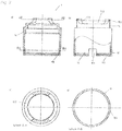
- Einhandhebelmischerkartusche consists essentially of a head piece 1, in which a spindle 2 protrudes axially, which is pivotally mounted in a rotatably mounted spindle receptacle 3 and engages in a slider 4 which is connected to a control disk 5, with a Passage disk 6 corresponds to which a bottom piece 8 connects, which receives a seal molding 7.
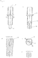
- the head piece 1 is sleeve-shaped and manufactured in the embodiment as a brass turned part. At its the bottom piece 8 facing end portion 10 diametrically to each other two rectangular recesses 101 are introduced into the head piece 1, are formed by the two arcuate webs 11, on the inside of a detent groove 111 is introduced. At its opposite ends of the webs 11, the head piece 1 has a reduced diameter portion 15, on the end circumferentially a nose 151 is formed. In the reduced diameter portion 15, two recesses 152 are diametrically opposed to each other, are formed by the respective two radial stops 153. The stops 153 are used to limit the rotation of the spindle receptacle 3. Below the diameter-reduced portion 15, a shoulder 14 is formed on the head piece 1 inside.
- a fastening ring 16 is further turned up.
- the mounting ring 16 has circumferentially outside an external thread 161 for screwing into a valve 1001.
- the fastening ring 16 is provided with an external hexagon 166.
- Below the hexagon socket 166 is in the mounting ring 16 inside a paragraph 165 formed.
- a nose 167 is formed at its outer hexagon 166 opposite end inside the mounting ring.
- the spindle 2 is formed in the embodiment substantially cuboid. Approximately in the middle of the spindle 2, an annular coaxial Anformung 21 for receiving a - not shown - keypad formed. Above the Anformung 21 a guided to the Anformung 21 slot 25 is introduced into the spindle 2. Below the Anformung 21 is introduced through the spindle 2, a bore 22 for receiving an axle pin 23. At the end, a control head 24 designed in the form of a spherical disk is integrally formed on the spindle 2 and is flattened on its side facing the slider 4.
- the spindle receptacle 3 is designed as a substantially cylindrical plastic injection-molded part.
- a two-step shoulder 31 is integrally formed on the spindle receptacle 3, the contour of which corresponds to the inner contour of the two-step shoulder 14 of the head piece 1 against which it bears.
- a radial through hole 32 for receiving the axle pin 23 for the spindle 2 is introduced through the spindle receptacle 3.
- the passage 33 terminates in a substantially parallelepiped-shaped receptacle 35 for the slider 4. Spaced to the receptacle 35 is in the spindle receptacle 3, a substantially oval indentation 36 for receiving the guide pin 44 of the slider 4 is introduced.
- the designed as a plastic injection molded slider 4 is formed substantially in the form of a circular disc on which a substantially cuboidal shaped piece 41 is integrally formed.
- the molding 41 is designed such that it can be displaced in the longitudinal direction within the receptacle 35 of the spindle receptacle 3 and in the transverse direction is guided. Axial is through the slider 4, the fitting 41 penetrating a slot 42 for receiving the control head 24 of the spindle 2 introduced. Laterally of the molding 41, a guide pin 44 is formed for engagement in the recess 36 of the spindle receptacle 3.
- two axial webs 43 for receiving the control disk 5 are integrally formed on the slider 4 on the outside.
- a dowel 45 is integrally formed on the underside for engagement in the fitting bore 53 of the control disk 5, whereby a positionally correct orientation of the control disk 5 is ensured during assembly.
- the control disk 5 is oval and made as a ceramic part. On its side facing the transmission disk 6, the control disk has a centrally arranged, egg-shaped indentation 51. On its upper side opposite the indentation 51, two recesses 52 for receiving the webs 23 of the slider 4 are inserted into the control disk 5 diametrically opposite each other on the outside. Furthermore, in the control disk 5 at its the slider 4 side facing a fitting bore 53 is introduced. About the recesses 52 and the fitting hole 53, the control disk 5 is positively connected to the slider 4.
- the transmission disk 6 is also designed as a ceramic part. Through the pass-through disk 6, two inlet channels 61 for cold or hot water and a relatively enlarged outlet channel 62 for the mixed water are introduced. The inlet channels 61 and the outlet channel 62 are guided at an angle to the aperture disk 6 through them. The side offset from each other on the transmission disc 6 three recesses 63 for positive connection with the bottom piece 8 are introduced.
- the seal molding 7 is made in the embodiment of rubber. It is essentially formed by three rings 71, which are each formed on the two remaining rings 71, so that a cloverleaf-like contour is formed. At the rings 71 of the seal molding 7 are at the top and at the bottom each sealing lips 72 formed. To stabilize the shape of the rings 71 are each provided with a support ring 73 which is disposed between the sealing lips 72 of the rings 71.
- the bottom piece 8 is substantially cylindrical. In the middle of the bottom piece 8, a cloverleaf-shaped receptacle for the sealing molding 7 is introduced. Surrounding the receptacle 81 spaced from each other three webs 82 are formed for rotationally fixed receiving the aperture plate 6. The webs 82 engage in the recesses 63 of the transmission disk 6. In order to improve the positive connection, lugs 821 are formed on two webs 82, which engage in recesses 63 of the transmission disk 6 corresponding thereto. Laterally, two shoulders 83 are formed on the bottom piece 8 diametrically opposite each other for engagement in the recesses 101 of the end-side section 10 of the head piece 1.
- two axial positioning pins 84 are further formed on the bottom piece 8.
- the positioning pins 84 are used for positioning the single lever mixer cartridge in a - not shown - fitting, which is provided for this purpose with corresponding positioning holes.
- Surrounding 8 locking lugs 85 are integrally formed on the bottom piece, which allow a latching connection between the bottom piece 8 and the head piece 1. The detents engage in the locking groove 111 of the arcuate webs 11 of the head piece 1 a.
- the heels 83 of the bottom piece 8 engage in the recesses 101 of the head piece 1.
- the arcuate webs 11 of the end-side section 10 of the head piece 1 project beyond the bottom surface 80 of the bottom piece 8 by 0.3 millimeters. From the bottom surface 80 protrude the two positioning pins 84 for positioning a - not shown - armature.
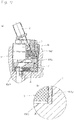
- the mixer cartridge will - as in FIG. 17 shown - connected via the mounting ring 16 with the valve 1001 and biased against the valve seat 1003 of the cartridge receptacle 1002 of the valve.
- the preload forces achieved thereby are transferred to the valve seat 1003 by the header via the end-side portion 10 protruding beyond the bottom surface 80 of the bottom piece 8.
- the mounting ring 16 is slipped over the reduced diameter portion 15 of the head piece 1, wherein the circumferential nose 151 is forced inwardly when passing the circumferential nose 167 of the mounting ring 16 inwardly. After passing through the nose 167 of the mounting ring 116, the nose 151 of the reduced-diameter portion 15 of the head piece 1 resumes its original position. The mounting ring 16 is thus held captive on the head piece 1. The screwing of the mounting ring 16 in the valve 1001 via the hexagon socket 166th
- the single-lever mixer cartridge is designed for valves with lateral water outlet.
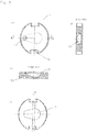
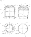
- a circumferential, diameter-enlarged shoulder 13 is arranged on the head piece 1, in the center circumferentially a groove 131 for receiving an O-ring 17 is introduced.
- a reduced diameter portion 15 is arranged, on the end circumferentially a nose 151 is formed.
- two recesses 152 are also diametrically opposed to each other, are formed by the respective two radial stops 153, which serve to limit the rotation of the spindle holder 3.
- two recesses 101 are introduced in the head piece 1 opposite, are formed by the arcuate webs 11.
- the recesses 101 are formed rectangular with different width, but identical height.
- a fastening ring 16 is turned up, the outside circumferentially a first external thread 161 for screwing a - not shown - fitting has.
- a reduced-diameter shoulder 62 is arranged, which is provided with a second external thread 163.
- End is on the mounting ring 16 formed a reduced diameter portion 164 through which a shoulder 165 is formed.
- the reduced-diameter portion 164 is also provided with an external hexagon 166.
- the diametrically reduced portion 164 opposite end inside the mounting ring is also also circumferentially a nose 167 formed.
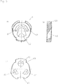
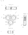
- the bottom piece 9 is substantially cylindrical.
- two inlet holes 91 and an outlet hole 92 are introduced, whose central axes define an isosceles triangle.
- the outlet bore 92 opens into a recess 93, which extends over the outer jacket 90 of the bottom piece 9.
- the bulge 93 allows sufficient water flow for a lateral outlet channel of a - not shown - fitting.
- the two inlet holes 91 are surrounded by a spectacle-shaped groove 94, which serves to receive a sealing molding 941.
- the groove 94 is positioned such that the boundary edge surrounding it passes through the center of the bottom surface 901 of the bottom piece 9.
- the bulge 93 flanking and opposite this are formed on the bottom piece 9 three axial positioning pins.
- the seal molding 941 is made of rubber in the embodiment. It is essentially formed by two rings 942, which are formed on each other, so that a spectacle-shaped contour is formed. Outside fitting lips 943 are integrally formed on the gasket molding, which abut in the lateral openings 940 of the groove 94. The outer contour of the mating lips 943 is formed such that it fits into the contour of the outer jacket 90 of the bottom piece 9.
- the so ausgestalte monobloc mixer cartridge is placed in a - not shown - fitting with a cartridge receptacle, at its open end an internal thread for screwing the mounting ring 16 of the head piece 1 is introduced.
- the cartridge receptacle of this - not shown - fitting open the bottom side in a valve seat two water inlet connections, which are sealed over the seal molding 941 against the inlet holes 91 and the surrounding a flat stop surface for supporting the end portion 10 of the head piece 1 is arranged.
- the head piece 1 is braced against the abutment surface of the valve seat via the fastening 16, which is screwed in the fitting (not shown), the clamping forces being transmitted directly to the abutment surface via the head piece 1.
- a lateral water drainage connection is arranged.
- the mixed water passes through the outlet bore 92 via the bulge 93 into the space of the cartridge receptacle and via this into the lateral water drain connection.
Claims (7)
- Robinetterie comprenant un logement de mitigeur qui présente un siège de vanne, logement dans lequel est montée une cartouche de mitigeur monocommande englobant une pièce têtière (1) configurée en forme de douille qui reçoit une pièce de fond (8, 9), ainsi qu'une commande par disque avec disque de commande (5) disposé de façon à pouvoir tourner et/ou se déplacer, via une broche (2) en appui rotatif et/ou pivotant, relativement à un disque de passage (6) qui épouse ledit disque de commande, disque de passage (6) contre lequel la pièce fond (8, 9) vient se raccorder, sachant que la pièce têtière (1) est serrée contre le siège de vanne via une bague de fixation (16) qui ceinture l'extérieur de la pièce têtière (1), caractérisée en ce que le segment (10) terminal de la pièce têtière (1) qui reçoit la pièce de fond (8, 9) est configuré de telle sorte qu'il dépasse au moins localement la surface (80, 901) de la pièce de fond (8, 9) qui ne regarde pas le disque de commande (5) et que la pièce de fond (8, 9) ne dépasse ce segment (10) à aucun endroit, sachant que le siège de vanne présente une surface butée plane sur laquelle applique le segment terminal de la pièce têtière de sorte que les forces de serrage agissant à la verticale sont directement communiquées à la surface butée via la pièce têtière.
- Robinetterie selon la revendication 1, caractérisée en ce que la pièce de fond (8) reçoit au moins un joint pour étanchéiser par rapport à un siège de vanne d'une robinetterie, joint qui dépasse le segment (10) terminal de la pièce têtière (1).
- Robinetterie selon la revendication 2, caractérisée en ce que la surface enveloppante (90) de la pièce de fond (9) est formée localement par un segment d'un joint (941).
- Robinetterie selon l'une des revendications précédentes, caractérisée en ce que le joint est formé par une pièce d'étanchéité moulée (7, 941) présentant au moins deux orifices de passage circulaires.
- Robinetterie selon l'une des revendications 2 à 4, caractérisée en ce que la pièce de fond (8, 9) est configurée de telle sorte que le centre de la pièce de fond (8, 9) se trouve sur le plan de sa surface de fond (80, 901) et n'est pas formé par un joint.
- Robinetterie selon l'une des revendications précédentes, caractérisée en ce que la cartouche de mitigeur est configurée comme vanne de sortie latérale.
- Robinetterie selon l'une des revendications précédentes, caractérisée en ce que la pièce têtière (1) est configurée en pièce en laiton usinée au tour.
Priority Applications (1)
| Application Number | Priority Date | Filing Date | Title |
|---|---|---|---|
| EP13774623.6A EP2962020B1 (fr) | 2013-03-01 | 2013-09-23 | Cartouche de mitigeur |
Applications Claiming Priority (3)
| Application Number | Priority Date | Filing Date | Title |
|---|---|---|---|
| EP13157471 | 2013-03-01 | ||
| EP13774623.6A EP2962020B1 (fr) | 2013-03-01 | 2013-09-23 | Cartouche de mitigeur |
| PCT/EP2013/069745 WO2014131471A1 (fr) | 2013-03-01 | 2013-09-23 | Cartouche de mitigeur |
Publications (2)
| Publication Number | Publication Date |
|---|---|
| EP2962020A1 EP2962020A1 (fr) | 2016-01-06 |
| EP2962020B1 true EP2962020B1 (fr) | 2017-07-12 |
Family
ID=47790066
Family Applications (1)
| Application Number | Title | Priority Date | Filing Date |
|---|---|---|---|
| EP13774623.6A Active EP2962020B1 (fr) | 2013-03-01 | 2013-09-23 | Cartouche de mitigeur |
Country Status (8)
| Country | Link |
|---|---|
| US (1) | US20160018011A1 (fr) |
| EP (1) | EP2962020B1 (fr) |
| KR (1) | KR102102500B1 (fr) |
| CN (1) | CN105190138B (fr) |
| ES (1) | ES2642365T3 (fr) |
| HU (1) | HUE034514T2 (fr) |
| TW (1) | TWI622723B (fr) |
| WO (1) | WO2014131471A1 (fr) |
Families Citing this family (4)
| Publication number | Priority date | Publication date | Assignee | Title |
|---|---|---|---|---|
| PT3693643T (pt) * | 2019-02-11 | 2021-04-05 | Fluehs Drehtechnik Gmbh | Parte superior de válvula para acessórios sanitários |
| US11149418B2 (en) * | 2019-02-22 | 2021-10-19 | Brasstech, Inc. | Faucet handle hub |
| EP3702651B1 (fr) * | 2019-02-28 | 2021-02-24 | Flühs Drehtechnik GmbH | Partie supérieure de soupape pour robinetteries sanitaires |
| DE102019126941B3 (de) * | 2019-10-08 | 2020-10-29 | Lisa Dräxlmaier GmbH | Magazinvorrichtung und verfahren zum zuführen von einlegeteilen in ein spritzgusswerkzeug |
Family Cites Families (12)
| Publication number | Priority date | Publication date | Assignee | Title |
|---|---|---|---|---|
| DE3244121A1 (de) * | 1982-11-29 | 1984-05-30 | Friedrich Grohe Armaturenfabrik Gmbh & Co, 5870 Hemer | Sanitaermischventil |
| IL73930A (en) * | 1984-12-25 | 1988-12-30 | Hamat Koor Metals Ltd | Mixing device for faucets |
| DE3738854A1 (de) * | 1987-11-16 | 1989-05-24 | Grohe Armaturen Friedrich | Wassermischventil |
| DE3903999A1 (de) * | 1989-02-10 | 1990-08-16 | Grohe Armaturen Friedrich | Sanitaeres mischventil |
| DE3903998A1 (de) * | 1989-02-10 | 1990-08-16 | Grohe Armaturen Friedrich | Mischventil fuer sanitaerarmaturen |
| DE3903997A1 (de) * | 1989-02-10 | 1990-08-16 | Grohe Armaturen Friedrich | Mischventil fuer sanitaerarmaturen |
| IT1257151B (it) * | 1992-09-16 | 1996-01-05 | Gevipi Ag | Cartuccia a piastre in materiale duro per un rubinetto a monocomando, del tipo con passaggi disposti al fondo. |
| FR2753771B1 (fr) * | 1996-09-20 | 1998-12-18 | Cartouche de robinet mitigeur a limitation ajustable de debit | |
| US6920899B2 (en) * | 2003-03-27 | 2005-07-26 | Masco Corporation Of Indiana | Fluid control valve |
| US7753074B2 (en) * | 2006-07-28 | 2010-07-13 | Masco Corporation Of Indiana | Mixing valve |
| HUP0800205A2 (en) * | 2008-04-01 | 2010-01-28 | Kerox Ipari Es Kereskedelmi Kf | Mixing faucet |
| HU230570B1 (hu) * | 2009-12-21 | 2016-12-28 | Kerox Ipari És Kereskedelmi Kft. | Egykaros keverő csaptelep betét megnövelt szögű komfort tartománnyal |
-
2013
- 2013-09-23 US US14/770,743 patent/US20160018011A1/en not_active Abandoned
- 2013-09-23 ES ES13774623.6T patent/ES2642365T3/es active Active
- 2013-09-23 CN CN201380074200.5A patent/CN105190138B/zh active Active
- 2013-09-23 WO PCT/EP2013/069745 patent/WO2014131471A1/fr active Application Filing
- 2013-09-23 HU HUE13774623A patent/HUE034514T2/en unknown
- 2013-09-23 EP EP13774623.6A patent/EP2962020B1/fr active Active
- 2013-09-23 KR KR1020157023615A patent/KR102102500B1/ko active IP Right Grant
- 2013-10-16 TW TW102137235A patent/TWI622723B/zh active
Non-Patent Citations (1)
| Title |
|---|
| None * |
Also Published As
| Publication number | Publication date |
|---|---|
| CN105190138A (zh) | 2015-12-23 |
| HUE034514T2 (en) | 2018-02-28 |
| KR102102500B1 (ko) | 2020-04-21 |
| TWI622723B (zh) | 2018-05-01 |
| US20160018011A1 (en) | 2016-01-21 |
| CN105190138B (zh) | 2018-06-08 |
| ES2642365T3 (es) | 2017-11-16 |
| KR20150120395A (ko) | 2015-10-27 |
| EP2962020A1 (fr) | 2016-01-06 |
| TW201435233A (zh) | 2014-09-16 |
| WO2014131471A1 (fr) | 2014-09-04 |
Similar Documents
| Publication | Publication Date | Title |
|---|---|---|
| EP2634464B1 (fr) | Cartouche de mélangeur à levier à une main | |
| EP2962020B1 (fr) | Cartouche de mitigeur | |
| EP1696158A1 (fr) | Tête de robinet | |
| EP2634463B1 (fr) | Cartouche de mélangeur à levier à une main | |
| EP1870526A1 (fr) | Robinet sanitaire | |
| EP2771600B1 (fr) | Cartouche pour mélangeur monocommande | |
| EP3074676B1 (fr) | Robinetterie sanitaire | |
| EP3062003B1 (fr) | Cartouche de mitigeur | |
| DE10305394A1 (de) | Flüssigkeitsventil für Heiz- und/oder Kühlanlagen | |
| DE3941106C2 (de) | Sanitäre Mischbatterie für den Wandanschluß | |
| EP2962021B1 (fr) | Cartouche de mitigeur | |
| DE202013100899U1 (de) | Einhandhebelkartusche | |
| DE2634721A1 (de) | Hydraulisches dreiwegeventil, insbesondere wasseranschluss fuer mund- und/ oder hautmassage- bzw. hautreinigungsduschen | |
| DE3537779C1 (en) | Valve | |
| DE202013104200U1 (de) | Einhandhebelkartusche | |
| EP3931474B1 (fr) | Robinet avec tuyau extensible | |
| WO2013010845A1 (fr) | Partie supérieure de soupape pour robinetterie | |
| EP3919789B1 (fr) | Armature sanitaire | |
| DE19913214A1 (de) | Ventilkartuschenanordnung | |
| DE202012100687U1 (de) | Einhandhebelmischerkartusche | |
| DE202015100918U1 (de) | Einhandhebelkartusche | |
| EP1632702B1 (fr) | Robinet mitigeur | |
| EP3064812B1 (fr) | Cartouche de mitigeur | |
| EP3062001A1 (fr) | Partie supérieure de soupape | |
| EP2829779B1 (fr) | Partie supérieure de soupape |
Legal Events
| Date | Code | Title | Description |
|---|---|---|---|
| PUAI | Public reference made under article 153(3) epc to a published international application that has entered the european phase |
Free format text: ORIGINAL CODE: 0009012 |
|
| 17P | Request for examination filed |
Effective date: 20150810 |
|
| AK | Designated contracting states |
Kind code of ref document: A1 Designated state(s): AL AT BE BG CH CY CZ DE DK EE ES FI FR GB GR HR HU IE IS IT LI LT LU LV MC MK MT NL NO PL PT RO RS SE SI SK SM TR |
|
| AX | Request for extension of the european patent |
Extension state: BA ME |
|
| DAX | Request for extension of the european patent (deleted) | ||
| REG | Reference to a national code |
Ref country code: DE Ref legal event code: R079 Ref document number: 502013007760 Country of ref document: DE Free format text: PREVIOUS MAIN CLASS: F16K0011078000 Ipc: F16K0031600000 |
|
| GRAP | Despatch of communication of intention to grant a patent |
Free format text: ORIGINAL CODE: EPIDOSNIGR1 |
|
| RIC1 | Information provided on ipc code assigned before grant |
Ipc: F16K 11/078 20060101ALI20170309BHEP Ipc: F16K 31/60 20060101AFI20170309BHEP Ipc: F16K 27/04 20060101ALI20170309BHEP |
|
| INTG | Intention to grant announced |
Effective date: 20170413 |
|
| GRAS | Grant fee paid |
Free format text: ORIGINAL CODE: EPIDOSNIGR3 |
|
| GRAA | (expected) grant |
Free format text: ORIGINAL CODE: 0009210 |
|
| AK | Designated contracting states |
Kind code of ref document: B1 Designated state(s): AL AT BE BG CH CY CZ DE DK EE ES FI FR GB GR HR HU IE IS IT LI LT LU LV MC MK MT NL NO PL PT RO RS SE SI SK SM TR |
|
| REG | Reference to a national code |
Ref country code: GB Ref legal event code: FG4D Free format text: NOT ENGLISH |
|
| REG | Reference to a national code |
Ref country code: CH Ref legal event code: EP |
|
| REG | Reference to a national code |
Ref country code: AT Ref legal event code: REF Ref document number: 908670 Country of ref document: AT Kind code of ref document: T Effective date: 20170715 |
|
| REG | Reference to a national code |
Ref country code: IE Ref legal event code: FG4D Free format text: LANGUAGE OF EP DOCUMENT: GERMAN |
|
| REG | Reference to a national code |
Ref country code: DE Ref legal event code: R096 Ref document number: 502013007760 Country of ref document: DE |
|
| REG | Reference to a national code |
Ref country code: NL Ref legal event code: MP Effective date: 20170712 |
|
| REG | Reference to a national code |
Ref country code: ES Ref legal event code: FG2A Ref document number: 2642365 Country of ref document: ES Kind code of ref document: T3 Effective date: 20171116 |
|
| REG | Reference to a national code |
Ref country code: LT Ref legal event code: MG4D |
|
| PG25 | Lapsed in a contracting state [announced via postgrant information from national office to epo] |
Ref country code: HR Free format text: LAPSE BECAUSE OF FAILURE TO SUBMIT A TRANSLATION OF THE DESCRIPTION OR TO PAY THE FEE WITHIN THE PRESCRIBED TIME-LIMIT Effective date: 20170712 Ref country code: NL Free format text: LAPSE BECAUSE OF FAILURE TO SUBMIT A TRANSLATION OF THE DESCRIPTION OR TO PAY THE FEE WITHIN THE PRESCRIBED TIME-LIMIT Effective date: 20170712 Ref country code: SE Free format text: LAPSE BECAUSE OF FAILURE TO SUBMIT A TRANSLATION OF THE DESCRIPTION OR TO PAY THE FEE WITHIN THE PRESCRIBED TIME-LIMIT Effective date: 20170712 Ref country code: LT Free format text: LAPSE BECAUSE OF FAILURE TO SUBMIT A TRANSLATION OF THE DESCRIPTION OR TO PAY THE FEE WITHIN THE PRESCRIBED TIME-LIMIT Effective date: 20170712 Ref country code: NO Free format text: LAPSE BECAUSE OF FAILURE TO SUBMIT A TRANSLATION OF THE DESCRIPTION OR TO PAY THE FEE WITHIN THE PRESCRIBED TIME-LIMIT Effective date: 20171012 Ref country code: FI Free format text: LAPSE BECAUSE OF FAILURE TO SUBMIT A TRANSLATION OF THE DESCRIPTION OR TO PAY THE FEE WITHIN THE PRESCRIBED TIME-LIMIT Effective date: 20170712 |
|
| PG25 | Lapsed in a contracting state [announced via postgrant information from national office to epo] |
Ref country code: IS Free format text: LAPSE BECAUSE OF FAILURE TO SUBMIT A TRANSLATION OF THE DESCRIPTION OR TO PAY THE FEE WITHIN THE PRESCRIBED TIME-LIMIT Effective date: 20171112 Ref country code: LV Free format text: LAPSE BECAUSE OF FAILURE TO SUBMIT A TRANSLATION OF THE DESCRIPTION OR TO PAY THE FEE WITHIN THE PRESCRIBED TIME-LIMIT Effective date: 20170712 Ref country code: PL Free format text: LAPSE BECAUSE OF FAILURE TO SUBMIT A TRANSLATION OF THE DESCRIPTION OR TO PAY THE FEE WITHIN THE PRESCRIBED TIME-LIMIT Effective date: 20170712 Ref country code: BG Free format text: LAPSE BECAUSE OF FAILURE TO SUBMIT A TRANSLATION OF THE DESCRIPTION OR TO PAY THE FEE WITHIN THE PRESCRIBED TIME-LIMIT Effective date: 20171012 Ref country code: GR Free format text: LAPSE BECAUSE OF FAILURE TO SUBMIT A TRANSLATION OF THE DESCRIPTION OR TO PAY THE FEE WITHIN THE PRESCRIBED TIME-LIMIT Effective date: 20171013 Ref country code: RS Free format text: LAPSE BECAUSE OF FAILURE TO SUBMIT A TRANSLATION OF THE DESCRIPTION OR TO PAY THE FEE WITHIN THE PRESCRIBED TIME-LIMIT Effective date: 20170712 |
|
| REG | Reference to a national code |
Ref country code: HU Ref legal event code: AG4A Ref document number: E034514 Country of ref document: HU |
|
| REG | Reference to a national code |
Ref country code: DE Ref legal event code: R097 Ref document number: 502013007760 Country of ref document: DE |
|
| PG25 | Lapsed in a contracting state [announced via postgrant information from national office to epo] |
Ref country code: RO Free format text: LAPSE BECAUSE OF FAILURE TO SUBMIT A TRANSLATION OF THE DESCRIPTION OR TO PAY THE FEE WITHIN THE PRESCRIBED TIME-LIMIT Effective date: 20170712 Ref country code: CZ Free format text: LAPSE BECAUSE OF FAILURE TO SUBMIT A TRANSLATION OF THE DESCRIPTION OR TO PAY THE FEE WITHIN THE PRESCRIBED TIME-LIMIT Effective date: 20170712 Ref country code: DK Free format text: LAPSE BECAUSE OF FAILURE TO SUBMIT A TRANSLATION OF THE DESCRIPTION OR TO PAY THE FEE WITHIN THE PRESCRIBED TIME-LIMIT Effective date: 20170712 |
|
| REG | Reference to a national code |
Ref country code: CH Ref legal event code: PL |
|
| PLBE | No opposition filed within time limit |
Free format text: ORIGINAL CODE: 0009261 |
|
| STAA | Information on the status of an ep patent application or granted ep patent |
Free format text: STATUS: NO OPPOSITION FILED WITHIN TIME LIMIT |
|
| PG25 | Lapsed in a contracting state [announced via postgrant information from national office to epo] |
Ref country code: SM Free format text: LAPSE BECAUSE OF FAILURE TO SUBMIT A TRANSLATION OF THE DESCRIPTION OR TO PAY THE FEE WITHIN THE PRESCRIBED TIME-LIMIT Effective date: 20170712 Ref country code: MC Free format text: LAPSE BECAUSE OF FAILURE TO SUBMIT A TRANSLATION OF THE DESCRIPTION OR TO PAY THE FEE WITHIN THE PRESCRIBED TIME-LIMIT Effective date: 20170712 Ref country code: SK Free format text: LAPSE BECAUSE OF FAILURE TO SUBMIT A TRANSLATION OF THE DESCRIPTION OR TO PAY THE FEE WITHIN THE PRESCRIBED TIME-LIMIT Effective date: 20170712 Ref country code: EE Free format text: LAPSE BECAUSE OF FAILURE TO SUBMIT A TRANSLATION OF THE DESCRIPTION OR TO PAY THE FEE WITHIN THE PRESCRIBED TIME-LIMIT Effective date: 20170712 |
|
| 26N | No opposition filed |
Effective date: 20180413 |
|
| GBPC | Gb: european patent ceased through non-payment of renewal fee |
Effective date: 20171012 |
|
| REG | Reference to a national code |
Ref country code: IE Ref legal event code: MM4A |
|
| REG | Reference to a national code |
Ref country code: BE Ref legal event code: MM Effective date: 20170930 |
|
| PG25 | Lapsed in a contracting state [announced via postgrant information from national office to epo] |
Ref country code: LU Free format text: LAPSE BECAUSE OF NON-PAYMENT OF DUE FEES Effective date: 20170923 |
|
| REG | Reference to a national code |
Ref country code: FR Ref legal event code: ST Effective date: 20180531 |
|
| PG25 | Lapsed in a contracting state [announced via postgrant information from national office to epo] |
Ref country code: GB Free format text: LAPSE BECAUSE OF NON-PAYMENT OF DUE FEES Effective date: 20171012 Ref country code: CH Free format text: LAPSE BECAUSE OF NON-PAYMENT OF DUE FEES Effective date: 20170930 Ref country code: IE Free format text: LAPSE BECAUSE OF NON-PAYMENT OF DUE FEES Effective date: 20170923 Ref country code: LI Free format text: LAPSE BECAUSE OF NON-PAYMENT OF DUE FEES Effective date: 20170930 |
|
| PG25 | Lapsed in a contracting state [announced via postgrant information from national office to epo] |
Ref country code: BE Free format text: LAPSE BECAUSE OF NON-PAYMENT OF DUE FEES Effective date: 20170930 Ref country code: SI Free format text: LAPSE BECAUSE OF FAILURE TO SUBMIT A TRANSLATION OF THE DESCRIPTION OR TO PAY THE FEE WITHIN THE PRESCRIBED TIME-LIMIT Effective date: 20170712 Ref country code: FR Free format text: LAPSE BECAUSE OF NON-PAYMENT OF DUE FEES Effective date: 20171002 |
|
| PG25 | Lapsed in a contracting state [announced via postgrant information from national office to epo] |
Ref country code: MT Free format text: LAPSE BECAUSE OF FAILURE TO SUBMIT A TRANSLATION OF THE DESCRIPTION OR TO PAY THE FEE WITHIN THE PRESCRIBED TIME-LIMIT Effective date: 20170712 |
|
| PG25 | Lapsed in a contracting state [announced via postgrant information from national office to epo] |
Ref country code: CY Free format text: LAPSE BECAUSE OF FAILURE TO SUBMIT A TRANSLATION OF THE DESCRIPTION OR TO PAY THE FEE WITHIN THE PRESCRIBED TIME-LIMIT Effective date: 20170712 |
|
| REG | Reference to a national code |
Ref country code: AT Ref legal event code: MM01 Ref document number: 908670 Country of ref document: AT Kind code of ref document: T Effective date: 20180923 |
|
| PG25 | Lapsed in a contracting state [announced via postgrant information from national office to epo] |
Ref country code: MK Free format text: LAPSE BECAUSE OF FAILURE TO SUBMIT A TRANSLATION OF THE DESCRIPTION OR TO PAY THE FEE WITHIN THE PRESCRIBED TIME-LIMIT Effective date: 20170712 |
|
| PG25 | Lapsed in a contracting state [announced via postgrant information from national office to epo] |
Ref country code: AT Free format text: LAPSE BECAUSE OF NON-PAYMENT OF DUE FEES Effective date: 20180923 |
|
| PG25 | Lapsed in a contracting state [announced via postgrant information from national office to epo] |
Ref country code: PT Free format text: LAPSE BECAUSE OF FAILURE TO SUBMIT A TRANSLATION OF THE DESCRIPTION OR TO PAY THE FEE WITHIN THE PRESCRIBED TIME-LIMIT Effective date: 20170712 |
|
| PG25 | Lapsed in a contracting state [announced via postgrant information from national office to epo] |
Ref country code: AL Free format text: LAPSE BECAUSE OF FAILURE TO SUBMIT A TRANSLATION OF THE DESCRIPTION OR TO PAY THE FEE WITHIN THE PRESCRIBED TIME-LIMIT Effective date: 20170712 |
|
| P01 | Opt-out of the competence of the unified patent court (upc) registered |
Effective date: 20230528 |
|
| PGFP | Annual fee paid to national office [announced via postgrant information from national office to epo] |
Ref country code: TR Payment date: 20230914 Year of fee payment: 11 |
|
| PGFP | Annual fee paid to national office [announced via postgrant information from national office to epo] |
Ref country code: HU Payment date: 20230916 Year of fee payment: 11 Ref country code: DE Payment date: 20230914 Year of fee payment: 11 |
|
| PGFP | Annual fee paid to national office [announced via postgrant information from national office to epo] |
Ref country code: ES Payment date: 20231019 Year of fee payment: 11 |
|
| PGFP | Annual fee paid to national office [announced via postgrant information from national office to epo] |
Ref country code: IT Payment date: 20230929 Year of fee payment: 11 |