EP2962020B1 - Single hand lever cartridge - Google Patents
Single hand lever cartridge Download PDFInfo
- Publication number
- EP2962020B1 EP2962020B1 EP13774623.6A EP13774623A EP2962020B1 EP 2962020 B1 EP2962020 B1 EP 2962020B1 EP 13774623 A EP13774623 A EP 13774623A EP 2962020 B1 EP2962020 B1 EP 2962020B1
- Authority
- EP
- European Patent Office
- Prior art keywords
- valve assembly
- bottom member
- accordance
- section
- designed
- Prior art date
- Legal status (The legal status is an assumption and is not a legal conclusion. Google has not performed a legal analysis and makes no representation as to the accuracy of the status listed.)
- Active
Links
- 238000007789 sealing Methods 0.000 claims description 12
- 229910001369 Brass Inorganic materials 0.000 claims description 2
- 239000010951 brass Substances 0.000 claims description 2
- XLYOFNOQVPJJNP-UHFFFAOYSA-N water Substances O XLYOFNOQVPJJNP-UHFFFAOYSA-N 0.000 description 15
- 238000000465 moulding Methods 0.000 description 14
- 230000005540 biological transmission Effects 0.000 description 9
- 239000004033 plastic Substances 0.000 description 4
- 238000011161 development Methods 0.000 description 3
- 230000018109 developmental process Effects 0.000 description 3
- 238000007373 indentation Methods 0.000 description 3
- 239000000919 ceramic Substances 0.000 description 2
- 230000000694 effects Effects 0.000 description 2
- 238000004519 manufacturing process Methods 0.000 description 2
- 230000013011 mating Effects 0.000 description 2
- 230000006735 deficit Effects 0.000 description 1
- 238000002347 injection Methods 0.000 description 1
- 239000007924 injection Substances 0.000 description 1
- 239000000463 material Substances 0.000 description 1
- 239000002991 molded plastic Substances 0.000 description 1
- 230000000149 penetrating effect Effects 0.000 description 1
- 230000036316 preload Effects 0.000 description 1
Images


Classifications
-
- F—MECHANICAL ENGINEERING; LIGHTING; HEATING; WEAPONS; BLASTING
- F16—ENGINEERING ELEMENTS AND UNITS; GENERAL MEASURES FOR PRODUCING AND MAINTAINING EFFECTIVE FUNCTIONING OF MACHINES OR INSTALLATIONS; THERMAL INSULATION IN GENERAL
- F16K—VALVES; TAPS; COCKS; ACTUATING-FLOATS; DEVICES FOR VENTING OR AERATING
- F16K11/00—Multiple-way valves, e.g. mixing valves; Pipe fittings incorporating such valves
- F16K11/02—Multiple-way valves, e.g. mixing valves; Pipe fittings incorporating such valves with all movable sealing faces moving as one unit
- F16K11/06—Multiple-way valves, e.g. mixing valves; Pipe fittings incorporating such valves with all movable sealing faces moving as one unit comprising only sliding valves, i.e. sliding closure elements
- F16K11/078—Multiple-way valves, e.g. mixing valves; Pipe fittings incorporating such valves with all movable sealing faces moving as one unit comprising only sliding valves, i.e. sliding closure elements with pivoted and linearly movable closure members
- F16K11/0782—Single-lever operated mixing valves with closure members having flat sealing faces
- F16K11/0787—Single-lever operated mixing valves with closure members having flat sealing faces with both the supply and the discharge passages being on the same side of the closure members
-
- F—MECHANICAL ENGINEERING; LIGHTING; HEATING; WEAPONS; BLASTING
- F16—ENGINEERING ELEMENTS AND UNITS; GENERAL MEASURES FOR PRODUCING AND MAINTAINING EFFECTIVE FUNCTIONING OF MACHINES OR INSTALLATIONS; THERMAL INSULATION IN GENERAL
- F16K—VALVES; TAPS; COCKS; ACTUATING-FLOATS; DEVICES FOR VENTING OR AERATING
- F16K27/00—Construction of housing; Use of materials therefor
- F16K27/04—Construction of housing; Use of materials therefor of sliding valves
- F16K27/044—Construction of housing; Use of materials therefor of sliding valves slide valves with flat obturating members
- F16K27/045—Construction of housing; Use of materials therefor of sliding valves slide valves with flat obturating members with pivotal obturating members
-
- F—MECHANICAL ENGINEERING; LIGHTING; HEATING; WEAPONS; BLASTING
- F16—ENGINEERING ELEMENTS AND UNITS; GENERAL MEASURES FOR PRODUCING AND MAINTAINING EFFECTIVE FUNCTIONING OF MACHINES OR INSTALLATIONS; THERMAL INSULATION IN GENERAL
- F16K—VALVES; TAPS; COCKS; ACTUATING-FLOATS; DEVICES FOR VENTING OR AERATING
- F16K31/00—Actuating devices; Operating means; Releasing devices
- F16K31/44—Mechanical actuating means
- F16K31/60—Handles
- F16K31/602—Pivoting levers, e.g. single-sided
Definitions
- the invention relates to a fitting with a valve seat having a cartridge seat, in which a Einhandhebelkartusche is introduced, according to the preamble of claim 1.
- a disadvantage of the known mixer cartridges that caused by the bias deformations of the base piece regularly made of plastic can occur in the mixer cartridge, whereby the tightness between the mixer cartridge and valve seat may be affected.
- the invention aims to remedy this situation.
- the invention is based on the object, a fitting with a valve seat having a cartridge receptacle, in which a Einhandhebelkartusche is introduced, in which a deformation of the bottom piece is avoided in the clamped state.
- this object is achieved in that the bottom piece receiving end portion of the head piece is designed such that it is at least partially flush with the bottom plate of the bottom piece facing away from the control disk.
- a single-lever mixer cartridge is created in which a deformation of the bottom piece is avoided in the clamped state of the mixer cartridge. Due to the design of the head piece such that the end piece receiving the bottom piece is at least partially flush with the bottom face of the bottom piece facing away from the control disk, or at least partially protruding over it, this end-side portion rests on the valve seat.
- the clamping forces are transmitted through the head directly to the valve seat, whereby setting effects of the plastic bottom piece formed are avoided.
- the end-side section particularly preferably completely projects beyond the bottom surface of the bottom piece, wherein recesses into which fastening heels of the bottom piece engage for its rotationally fixed fixing are negligible. It is essential that the bottom piece at no point projects beyond the end-side portion of the head piece.
- the bottom piece receives at least one seal for sealing against a valve seat of a fitting, which projects beyond the end-side section of the head piece.
- the lateral surface of the bottom piece is partially formed by a portion of a seal. As a result, a small component dimensioning of the bottom piece is achieved.
- the bottom piece is designed such that the center of the bottom piece lies on the plane of the bottom surface and is not formed by a seal.
- valve upper part is designed as a side outlet valve.
- a lateral water outlet is required.
- Such a lateral water outlet is realized in that the bottom of the mixer cartridge is designed such that the escaping water between the bottom of the cartridge and the bottom of the receptacle of the valve exit and can be performed by a lateral outlet of the valve.
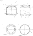
- Einhandhebelmischerkartusche consists essentially of a head piece 1, in which a spindle 2 protrudes axially, which is pivotally mounted in a rotatably mounted spindle receptacle 3 and engages in a slider 4 which is connected to a control disk 5, with a Passage disk 6 corresponds to which a bottom piece 8 connects, which receives a seal molding 7.
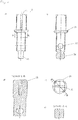
- the head piece 1 is sleeve-shaped and manufactured in the embodiment as a brass turned part. At its the bottom piece 8 facing end portion 10 diametrically to each other two rectangular recesses 101 are introduced into the head piece 1, are formed by the two arcuate webs 11, on the inside of a detent groove 111 is introduced. At its opposite ends of the webs 11, the head piece 1 has a reduced diameter portion 15, on the end circumferentially a nose 151 is formed. In the reduced diameter portion 15, two recesses 152 are diametrically opposed to each other, are formed by the respective two radial stops 153. The stops 153 are used to limit the rotation of the spindle receptacle 3. Below the diameter-reduced portion 15, a shoulder 14 is formed on the head piece 1 inside.
- a fastening ring 16 is further turned up.
- the mounting ring 16 has circumferentially outside an external thread 161 for screwing into a valve 1001.
- the fastening ring 16 is provided with an external hexagon 166.
- Below the hexagon socket 166 is in the mounting ring 16 inside a paragraph 165 formed.
- a nose 167 is formed at its outer hexagon 166 opposite end inside the mounting ring.
- the spindle 2 is formed in the embodiment substantially cuboid. Approximately in the middle of the spindle 2, an annular coaxial Anformung 21 for receiving a - not shown - keypad formed. Above the Anformung 21 a guided to the Anformung 21 slot 25 is introduced into the spindle 2. Below the Anformung 21 is introduced through the spindle 2, a bore 22 for receiving an axle pin 23. At the end, a control head 24 designed in the form of a spherical disk is integrally formed on the spindle 2 and is flattened on its side facing the slider 4.
- the spindle receptacle 3 is designed as a substantially cylindrical plastic injection-molded part.
- a two-step shoulder 31 is integrally formed on the spindle receptacle 3, the contour of which corresponds to the inner contour of the two-step shoulder 14 of the head piece 1 against which it bears.
- a radial through hole 32 for receiving the axle pin 23 for the spindle 2 is introduced through the spindle receptacle 3.
- the passage 33 terminates in a substantially parallelepiped-shaped receptacle 35 for the slider 4. Spaced to the receptacle 35 is in the spindle receptacle 3, a substantially oval indentation 36 for receiving the guide pin 44 of the slider 4 is introduced.
- the designed as a plastic injection molded slider 4 is formed substantially in the form of a circular disc on which a substantially cuboidal shaped piece 41 is integrally formed.
- the molding 41 is designed such that it can be displaced in the longitudinal direction within the receptacle 35 of the spindle receptacle 3 and in the transverse direction is guided. Axial is through the slider 4, the fitting 41 penetrating a slot 42 for receiving the control head 24 of the spindle 2 introduced. Laterally of the molding 41, a guide pin 44 is formed for engagement in the recess 36 of the spindle receptacle 3.
- two axial webs 43 for receiving the control disk 5 are integrally formed on the slider 4 on the outside.
- a dowel 45 is integrally formed on the underside for engagement in the fitting bore 53 of the control disk 5, whereby a positionally correct orientation of the control disk 5 is ensured during assembly.
- the control disk 5 is oval and made as a ceramic part. On its side facing the transmission disk 6, the control disk has a centrally arranged, egg-shaped indentation 51. On its upper side opposite the indentation 51, two recesses 52 for receiving the webs 23 of the slider 4 are inserted into the control disk 5 diametrically opposite each other on the outside. Furthermore, in the control disk 5 at its the slider 4 side facing a fitting bore 53 is introduced. About the recesses 52 and the fitting hole 53, the control disk 5 is positively connected to the slider 4.
- the transmission disk 6 is also designed as a ceramic part. Through the pass-through disk 6, two inlet channels 61 for cold or hot water and a relatively enlarged outlet channel 62 for the mixed water are introduced. The inlet channels 61 and the outlet channel 62 are guided at an angle to the aperture disk 6 through them. The side offset from each other on the transmission disc 6 three recesses 63 for positive connection with the bottom piece 8 are introduced.
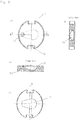
- the seal molding 7 is made in the embodiment of rubber. It is essentially formed by three rings 71, which are each formed on the two remaining rings 71, so that a cloverleaf-like contour is formed. At the rings 71 of the seal molding 7 are at the top and at the bottom each sealing lips 72 formed. To stabilize the shape of the rings 71 are each provided with a support ring 73 which is disposed between the sealing lips 72 of the rings 71.
- the bottom piece 8 is substantially cylindrical. In the middle of the bottom piece 8, a cloverleaf-shaped receptacle for the sealing molding 7 is introduced. Surrounding the receptacle 81 spaced from each other three webs 82 are formed for rotationally fixed receiving the aperture plate 6. The webs 82 engage in the recesses 63 of the transmission disk 6. In order to improve the positive connection, lugs 821 are formed on two webs 82, which engage in recesses 63 of the transmission disk 6 corresponding thereto. Laterally, two shoulders 83 are formed on the bottom piece 8 diametrically opposite each other for engagement in the recesses 101 of the end-side section 10 of the head piece 1.
- two axial positioning pins 84 are further formed on the bottom piece 8.
- the positioning pins 84 are used for positioning the single lever mixer cartridge in a - not shown - fitting, which is provided for this purpose with corresponding positioning holes.
- Surrounding 8 locking lugs 85 are integrally formed on the bottom piece, which allow a latching connection between the bottom piece 8 and the head piece 1. The detents engage in the locking groove 111 of the arcuate webs 11 of the head piece 1 a.
- the heels 83 of the bottom piece 8 engage in the recesses 101 of the head piece 1.
- the arcuate webs 11 of the end-side section 10 of the head piece 1 project beyond the bottom surface 80 of the bottom piece 8 by 0.3 millimeters. From the bottom surface 80 protrude the two positioning pins 84 for positioning a - not shown - armature.
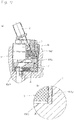
- the mixer cartridge will - as in FIG. 17 shown - connected via the mounting ring 16 with the valve 1001 and biased against the valve seat 1003 of the cartridge receptacle 1002 of the valve.
- the preload forces achieved thereby are transferred to the valve seat 1003 by the header via the end-side portion 10 protruding beyond the bottom surface 80 of the bottom piece 8.
- the mounting ring 16 is slipped over the reduced diameter portion 15 of the head piece 1, wherein the circumferential nose 151 is forced inwardly when passing the circumferential nose 167 of the mounting ring 16 inwardly. After passing through the nose 167 of the mounting ring 116, the nose 151 of the reduced-diameter portion 15 of the head piece 1 resumes its original position. The mounting ring 16 is thus held captive on the head piece 1. The screwing of the mounting ring 16 in the valve 1001 via the hexagon socket 166th
- the single-lever mixer cartridge is designed for valves with lateral water outlet.
- a circumferential, diameter-enlarged shoulder 13 is arranged on the head piece 1, in the center circumferentially a groove 131 for receiving an O-ring 17 is introduced.
- a reduced diameter portion 15 is arranged, on the end circumferentially a nose 151 is formed.
- two recesses 152 are also diametrically opposed to each other, are formed by the respective two radial stops 153, which serve to limit the rotation of the spindle holder 3.
- two recesses 101 are introduced in the head piece 1 opposite, are formed by the arcuate webs 11.
- the recesses 101 are formed rectangular with different width, but identical height.
- a fastening ring 16 is turned up, the outside circumferentially a first external thread 161 for screwing a - not shown - fitting has.
- a reduced-diameter shoulder 62 is arranged, which is provided with a second external thread 163.
- End is on the mounting ring 16 formed a reduced diameter portion 164 through which a shoulder 165 is formed.
- the reduced-diameter portion 164 is also provided with an external hexagon 166.
- the diametrically reduced portion 164 opposite end inside the mounting ring is also also circumferentially a nose 167 formed.
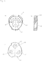
- the bottom piece 9 is substantially cylindrical.
- two inlet holes 91 and an outlet hole 92 are introduced, whose central axes define an isosceles triangle.
- the outlet bore 92 opens into a recess 93, which extends over the outer jacket 90 of the bottom piece 9.
- the bulge 93 allows sufficient water flow for a lateral outlet channel of a - not shown - fitting.
- the two inlet holes 91 are surrounded by a spectacle-shaped groove 94, which serves to receive a sealing molding 941.
- the groove 94 is positioned such that the boundary edge surrounding it passes through the center of the bottom surface 901 of the bottom piece 9.
- the bulge 93 flanking and opposite this are formed on the bottom piece 9 three axial positioning pins.
- the seal molding 941 is made of rubber in the embodiment. It is essentially formed by two rings 942, which are formed on each other, so that a spectacle-shaped contour is formed. Outside fitting lips 943 are integrally formed on the gasket molding, which abut in the lateral openings 940 of the groove 94. The outer contour of the mating lips 943 is formed such that it fits into the contour of the outer jacket 90 of the bottom piece 9.
- the so ausgestalte monobloc mixer cartridge is placed in a - not shown - fitting with a cartridge receptacle, at its open end an internal thread for screwing the mounting ring 16 of the head piece 1 is introduced.
- the cartridge receptacle of this - not shown - fitting open the bottom side in a valve seat two water inlet connections, which are sealed over the seal molding 941 against the inlet holes 91 and the surrounding a flat stop surface for supporting the end portion 10 of the head piece 1 is arranged.
- the head piece 1 is braced against the abutment surface of the valve seat via the fastening 16, which is screwed in the fitting (not shown), the clamping forces being transmitted directly to the abutment surface via the head piece 1.
- a lateral water drainage connection is arranged.
- the mixed water passes through the outlet bore 92 via the bulge 93 into the space of the cartridge receptacle and via this into the lateral water drain connection.
Description
Die Erfindung betrifft eine Armatur mit einer einen Ventilsitz aufweisenden Kartuschenaufnahme, in die eine Einhandhebelkartusche eingebracht ist, nach dem Oberbegriff des Patentanspruchs 1.The invention relates to a fitting with a valve seat having a cartridge seat, in which a Einhandhebelkartusche is introduced, according to the preamble of
In Sanitärarmaturen werden häufig als Mischerkartuschen ausgeführte Einhandhebelkartuschen eingesetzt in denen eine eine Steuerscheibe sowie eine Durchlassscheibe aufweisende Scheibensteuerung angeordnet ist, welche über einen einzigen Hebel derart bedienbar ist, dass sowohl die Wassermenge als auch die Wassertemperatur über ein und denselben Hebel steuerbar ist. Derartige austauschbare Kartuschen, wie sie beispielsweise in der
Bei der Gestaltung von Armaturengehäusen besteht zunehmend der Wunsch, nach einem möglichst kleinen Aufbau. Daher ist es erforderlich, die Mischerkartuschen klein und kompakt aufzubauen, wobei gleichzeitig die Anforderung nach einer großen Wassermenge gegeben ist. Mischerkartuschen sind regelmäßig aus Kunststoffspritzgußteilen zusammengesetzt, wobei aufgrund der kleinen Dimensionierung der Bauteile, verbunden mit großzügig dimensionierten Durchlassöffnungen für den Wasserdurchtritt bereichsweise nur geringe Materialstärken vorhanden sind. Die Mischerkartuschen werden in dem Armaturengehäuse gegen einen Ventilsitz verspannt, um die erforderliche Dichtigkeit zu gewährleisten. Die Verspannung erfolgt regelmäßig über einen Befestigungsring, der an seinen dem Ventilsitz gegenüberliegenden Ende des Kopfstücks der Mischerkartusche angeordnet und in das Armaturengehäuse eingeschraubt wird, wodurch die Vorspannung erzielt wird.In the design of valve bodies, there is an increasing desire for the smallest possible structure. Therefore, it is necessary to build the mixer cartridges small and compact, while at the same time the requirement for a large amount of water is given. Mixer cartridges are regularly composed of injection-molded plastic parts, and due to the small dimensions of the components, connected with generously dimensioned passage openings for the passage of water, in places only small material thicknesses are present. The mixer cartridges are clamped in the valve body against a valve seat to ensure the required tightness. The clamping is carried out regularly via a fastening ring, which is arranged at its opposite end of the valve seat of the head piece of the mixer cartridge and screwed into the valve body, whereby the bias voltage is achieved.
Nachteilig an den vorbekannten Mischerkartuschen ist, dass bedingt durch die Vorspannung Verformungen des regelmäßig aus Kunststoff hergestellten Bodenstücks der Mischerkartusche auftreten können, wodurch die Dichtheit zwischen Mischerkartusche und Ventilsitz beeinträchtigt sein kann.A disadvantage of the known mixer cartridges that caused by the bias deformations of the base piece regularly made of plastic can occur in the mixer cartridge, whereby the tightness between the mixer cartridge and valve seat may be affected.
Hier will die Erfindung Abhilfe schaffen. Der Erfindung liegt die Aufgabe zu Grunde, eine Armatur mit einer einen Ventilsitz aufweisenden Kartuschenaufnahme, in die eine Einhandhebelkartusche eingebracht ist bereitzustellen, bei der eine Verformung des Bodenstücks im eingespannten Zustand vermieden ist. Gemäß der Erfindung wird diese Aufgabe dadurch gelöst, dass der das Bodenstück aufnehmende endseitige Abschnitt des Kopfstücks derart ausgebildet ist, dass er mit der der Steuerscheibe abgewandten Bodenfläche des Bodenstücks zumindest bereichsweise zumindest bündig ist.The invention aims to remedy this situation. The invention is based on the object, a fitting with a valve seat having a cartridge receptacle, in which a Einhandhebelkartusche is introduced, in which a deformation of the bottom piece is avoided in the clamped state. According to the invention, this object is achieved in that the bottom piece receiving end portion of the head piece is designed such that it is at least partially flush with the bottom plate of the bottom piece facing away from the control disk.
Mit der Erfindung ist eine Einhandhebelmischerkartusche geschaffen, bei der eine Verformung des Bodenstücks im eingespannten Zustand der Mischerkartusche vermieden ist. Durch die Gestaltung des Kopfstücks derart, dass der das Bodenstück aufnehmende endseitige Abschnitt mit der der Steuerscheibe abgewandten Bodenfläche des Bodenstücks zumindest bereichsweise zumindest bündig ist bzw. diese vorzugsweise zumindest bereichsweise überragt, ist bewirkt, dass dieser endseitige Abschnitt auf dem Ventilsitz aufliegt. Die Spannkräfte werden so durch das Kopfstück direkt auf den Ventilsitz übertragen, wodurch Setzeffekte des aus Kunststoff ausgebildeten Bodenstücks vermieden sind. Zur gleichmäßigen Übertragung der Spannkräfte auf den Ventilsitz einer Armatur überragt der endseitige Abschnitt die Bodenfläche des Bodenstücks besonders bevorzugt vollständig, wobei Aussparungen, in die Befestigungsabsätze des Bodenstücks zu dessen drehfesten Fixierung eingreifen, zu vernachlässigen sind. Wesentlich ist, dass das Bodenstück an keiner Stelle den endseitigen Abschnitt des Kopfstücks überragt.With the invention, a single-lever mixer cartridge is created in which a deformation of the bottom piece is avoided in the clamped state of the mixer cartridge. Due to the design of the head piece such that the end piece receiving the bottom piece is at least partially flush with the bottom face of the bottom piece facing away from the control disk, or at least partially protruding over it, this end-side portion rests on the valve seat. The clamping forces are transmitted through the head directly to the valve seat, whereby setting effects of the plastic bottom piece formed are avoided. For uniform transmission of the clamping forces on the valve seat of a valve, the end-side section particularly preferably completely projects beyond the bottom surface of the bottom piece, wherein recesses into which fastening heels of the bottom piece engage for its rotationally fixed fixing are negligible. It is essential that the bottom piece at no point projects beyond the end-side portion of the head piece.
In Weiterbildung der Erfindung nimmt das Bodenstück wenigstens eine Dichtung zur Abdichtung gegenüber einem Ventilsitz einer Armatur auf, welche den endseitigen Abschnitt des Kopfstücks überragt. Hierdurch ist eine definierte Verformbarkeit der Dichtung erzielt, wodurch eine zuverlässige Dichtwirkung gewährleistet ist. Eine Beschädigung der Dichtung durch übermässige Verspannung ist so vermieden.In a further development of the invention, the bottom piece receives at least one seal for sealing against a valve seat of a fitting, which projects beyond the end-side section of the head piece. This is a defined deformability achieved the seal, whereby a reliable sealing effect is ensured. Damage to the seal due to excessive tension is avoided.
In weiterer Ausgestaltung der Erfindung ist die Mantelfläche des Bodenstücks bereichsweise durch einen Abschnitt einer Dichtung gebildet. Hierdurch ist eine geringe Bauteildimensionierung des Bodenstücks erzielt.In a further embodiment of the invention, the lateral surface of the bottom piece is partially formed by a portion of a seal. As a result, a small component dimensioning of the bottom piece is achieved.
In Weiterbildung der Erfindung ist das Bodenstück derart ausgebildet, dass der Mittelpunkt des Bodenstücks auf der Ebene dessen Bodenfläche liegt und nicht durch eine Dichtung gebildet ist. Hierdurch ist eine Beeinträchtigung der Dichtung bzw. der Dichtungsauflage durch Fertigungstoleranzen des Ventilsitzes vermieden, welche beispielsweise durch die Zentrierspitze des Bohrers im Zuge der Herstellung verursacht sind.In a further development of the invention, the bottom piece is designed such that the center of the bottom piece lies on the plane of the bottom surface and is not formed by a seal. As a result, an impairment of the seal or the seal support is avoided by manufacturing tolerances of the valve seat, which are caused for example by the centering of the drill in the course of production.
In weiterer Ausgestaltung der Erfindung ist das Ventiloberteil als Seitenauslaufventil ausgebildet. Bei der Gestaltung von Armaturen wird oftmals auch ein seitlicher Wasserauslauf gefordert. Ein solcher seitlicher Wasseraustritt wird dadurch realisiert, dass der Boden der Mischerkartusche derart ausgebildet ist, dass das austretende Wasser zwischen dem Bodenstück der Kartusche und dem Boden der Aufnahme der Armatur austreten und durch einen seitlichen Auslauf der Armatur geführt werden kann.In a further embodiment of the invention, the valve upper part is designed as a side outlet valve. In the design of valves often a lateral water outlet is required. Such a lateral water outlet is realized in that the bottom of the mixer cartridge is designed such that the escaping water between the bottom of the cartridge and the bottom of the receptacle of the valve exit and can be performed by a lateral outlet of the valve.
Andere Weiterbildungen und Ausgestaltungen der Erfindung sind in den übrigen Unteransprüchen angegeben. Ausführungsbeispiele der Erfindung sind in denOther developments and refinements of the invention are specified in the remaining subclaims. Embodiments of the invention are in the
Zeichnungen dargestellt und werden nachfolgend im Einzelnen beschrieben. Es zeigen:
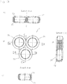
Figur 1- die schematische Darstellung einer Einhandhebelmischerkartusche
- a) in der Ansicht von unten;
- b) im Teillängsschnitt;
- c) in der Seitenansicht;
- d) in der Draufsicht;
Figur 2- die schematische Darstellung des Kopfstücks der Mischerkartusche aus
Figur 1- a) im Längsschnitt;
- b) im Teilschnitt in um 90° gedrehter Seitenansicht
- c) im Querschnitt (Schnitt A-A);
- d) im Querschnitt (Schnitt B-B);
Figur 3- die schematische Darstellung der Spindelaufnahme der Mischerkartusche aus
Figur 1- a) in der Draufsicht;
- b) in der Seitenansicht;
- c) im Längsschnitt (Schnitt A-A);
- d) in der Ansicht von unten;
Figur 4- die Spindel der Mischerkartusche aus
Figur 1- a) in der Seitenansicht;
- b) im Teilschnitt in um 90° gedrehter Seitenansicht
- c) in der Draufsicht;
- d) im Längsschnitt (Schnitt B-B);
- e) im Querschnitt (Schnitt A-A);
Figur 5- die Schwenkachse der Spindel der Mischerkartusche aus
Figur 1 Figur 6- den Befestigungsring der Mischerkartusche aus
Figur 1- a) im Längsschnitt;
- b) in der Draufsicht;
Figur 7- die schematische Darstellung des Gleitstücks der Mischerkartusche aus
Figur 1- a) in der Ansicht von unten ;
- b) im Querschnitt ;
- c) in der Draufsicht;
- d) in der Seitenansicht;
Figur 8- die Darstellung der Steuerscheibe der Mischerkartusche aus Figur 1
- a) in der Ansicht von unten;
- b) im Querschnitt (Schnitt A-A);
- c) in der Draufsicht;
- d) im Querschnitt (Schnitt B-B);
- Figur 9
- die Darstellung der Durchlassscheibe der Mischerkartusche aus
Figur 1 - a) in der Ansicht von unten;
- b) im Querschnitt;
- c) in der Draufsicht;
Figur 10- die Darstellung des Bodenstücks des Mischerkartusche aus Figur 1
- a) in der Ansicht von unten;
- b) in der Seitenansicht;
- c) in der Draufsicht;
- d) im Teilschnitt;
- e) im Querschnitt (Schnitt A-A);
- f) im Querschnitt (Schnitt B-B);
Figur 11- die Darstellung des Lippendichtungformteils der Mischerkartusche aus
Figur 1 - a) in der Draufsicht;
- b) im Längsschnitt (Schnitt A-A);
- c) im Längsschnitt (Schnitt B-B);
- d) im Längsschnitt (Schnitt C-C);
- Figur 12
- die schematische Darstellung einer Einhandhebelmischerkartusche in einer weiteren Ausführungsform für eine Armatur mit seitlichem Auslauf
- a) in der Ansicht von unten;
- b) im Längsschnitt;
- c) in der Seitenansicht;
- d) in der Draufsicht;
Figur 13- die schematische Darstellung des Kopfstücks der Mischerkartusche aus
Figur 12 - a) im Längsschnitt;
- b) im Teilschnitt in
um 90° gedrehter Seitenansicht - c) im Querschnitt (Schnitt A-A);
- d) im Querschnitt (Schnitt B-B);
Figur 14- den Befestigungsring der Mischerkartusche aus
Figur 12 - a) im Längsschnitt;
- b) in der Draufsicht;
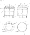
Figur 15- die Darstellung des Bodenstückes des Mischerkartusche aus Figur 12
- a) in der Ansicht von unten;
- b) in Teilschnittdarstellung;
- c) in der Seitenansicht;
- d) in der um 90° verdrehten Seitenansicht;
- e) in der Draufsicht;
- f) im Querschnitt (Schnitt A-A);
- g) im Querschnitt (Schnitt B-B);
- h) im Querschnitt (Schnitt C-C);
- i) im Querschnitt (Schnitt D-D);
Figur 16- die Darstellung des Lippendichtungformteils der Mischerkartusche aus
Figur 12 - a) in der Seitenansicht im Teilschnitt;
- b) in der Draufsicht.
Figur 17- die Darstellung der in einer Armatur angebrachten Mischerkartusche aus
Figur 1 - a) im Längsschnitt
- b) in Detaildarstellung des Ausschnitts "X"
- FIG. 1
- the schematic representation of a Einhandhebelmischerkartusche
- a) in the view from below;
- b) in partial longitudinal section;
- c) in side view;
- d) in plan view;
- FIG. 2
- the schematic representation of the head of the mixer cartridge
FIG. 1 - a) in longitudinal section;
- b) in partial section in 90 ° rotated side view
- c) in cross section (section AA);
- d) in cross-section (section BB);
- FIG. 3
- the schematic representation of the spindle receptacle of the mixer cartridge
FIG. 1 - a) in plan view;
- b) in side view;
- c) in longitudinal section (section AA);
- d) in the view from below;
- FIG. 4
- the spindle of the mixer cartridge off
FIG. 1 - a) in side view;
- b) in partial section in 90 ° rotated side view
- c) in plan view;
- d) in longitudinal section (section BB);
- e) in cross-section (section AA);
- FIG. 5
- the pivot axis of the spindle of the mixer cartridge off
FIG. 1 ; - FIG. 6
- from the mounting ring of the mixer cartridge
FIG. 1 - a) in longitudinal section;
- b) in plan view;
- FIG. 7
- the schematic representation of the slider of the mixer cartridge
FIG. 1 - a) in the view from below;
- b) in cross section;
- c) in plan view;
- d) in side view;
- FIG. 8
- the representation of the control disk of the mixer cartridge of Figure 1
- a) in the view from below;
- b) in cross-section (section AA);
- c) in plan view;
- d) in cross-section (section BB);
- FIG. 9
- the representation of the passage disc of the mixer cartridge
FIG. 1 - a) in the view from below;
- b) in cross section;
- c) in plan view;
- FIG. 10
- the representation of the bottom piece of the mixer cartridge of Figure 1
- a) in the view from below;
- b) in side view;
- c) in plan view;
- d) in partial section;
- e) in cross-section (section AA);
- f) in cross section (section BB);
- FIG. 11
- the representation of the lip seal molding of the mixer cartridge
FIG. 1 - a) in plan view;
- b) in longitudinal section (section AA);
- c) in longitudinal section (section BB);
- d) in longitudinal section (section CC);
- FIG. 12
- the schematic representation of a Einhandhebelmischerkartusche in another embodiment for a fitting with a side outlet
- a) in the view from below;
- b) in longitudinal section;
- c) in side view;
- d) in plan view;
- FIG. 13
- the schematic representation of the head of the mixer cartridge
FIG. 12 - a) in longitudinal section;
- b) in partial section in 90 ° rotated side view
- c) in cross section (section AA);
- d) in cross-section (section BB);
- FIG. 14
- from the mounting ring of the mixer cartridge
FIG. 12 - a) in longitudinal section;
- b) in plan view;
- FIG. 15
- the representation of the bottom piece of the mixer cartridge of Figure 12
- a) in the view from below;
- b) in partial section;
- c) in side view;
- d) in the rotated by 90 ° side view;
- e) in plan view;
- f) in cross section (section AA);
- g) in cross section (section BB);
- h) in cross section (section CC);
- i) in cross section (section DD);
- FIG. 16
- the representation of the lip seal molding of the mixer cartridge
FIG. 12 - a) in side view in partial section;
- b) in plan view.
- FIG. 17
- the representation of mounted in a mixer mixer cartridge
FIG. 1 - a) in longitudinal section
- b) in detail of the section "X"
Die als Ausführungsbeispiel gewählte Einhandhebelmischerkartusche besteht im Wesentlichen aus einem Kopfstück 1, in das eine Spindel 2 axial hineinragt, die in einer drehbar gelagerten Spindelaufnahme 3 schwenkbar gelagert ist und die in ein Gleitstück 4 eingreift, das mit einer Steuerscheibe 5 verbunden ist, die mit einer Durchlassscheibe 6 korrespondiert, an die sich ein Bodenstück 8 anschließt, welches ein Dichtungsformteil 7 aufnimmt.The chosen as an exemplary embodiment Einhandhebelmischerkartusche consists essentially of a
Das Kopfstück 1 ist hülsenartig ausgebildet und im Ausführungsbeispiel als Messingdrehteil hergestellt. An seinen dem Bodenstück 8 zugewandten endseitigen Abschnitt 10 sind in das Kopfstück 1 diametral zueinander zwei rechteckförmige Ausnehmungen 101 eingebracht, durch die zwei bogenförmige Stege 11 gebildet sind, an deren Innenseite eine Rastnut 111 eingebracht ist. An seinen den Stegen 11 gegenüberliegenden Ende weist das Kopfstück 1 einen durchmesserreduzierten Abschnitt 15 auf, an dem endseitig umlaufend eine Nase 151 angeformt ist. In den durchmesserreduzierten Abschnitt 15 sind diametral zueinander zwei Ausnehmungen 152 eingebracht, durch die jeweils zwei radiale Anschläge 153 gebildet sind. Die Anschläge 153 dienen der Drehbegrenzung der Spindelaufnahme 3. Unterhalb des durchmesserreduzierten Abschnitts 15 ist an dem Kopfstück 1 innen ein Absatz 14 ausgebildet.The
Auf den durchmesserreduzierten Abschnitt 15 des Kopfstücks 1 ist weiterhin ein Befestigungsring 16 aufgestülpt. Der Befestigungsring 16 weist außen umlaufend ein Außengewinde 161 zum Einschrauben in eine Armatur 1001 auf. Oberhalb des Außengewindes 161 ist der Befestigungsring 16 mit einem Außensechskant 166 versehen. Unterhalb des Außensechskants 166 ist in dem Befestigungsring 16 innen ein Absatz 165 gebildet. An seinen dem Außensechskant 166 entgegengesetzten Ende ist innen in dem Befestigungsring weiterhin umlaufend eine Nase 167 angeformt.On the reduced
Die Spindel 2 ist im Ausführungsbeispiel im Wesentlichen quaderförmig ausgebildet. Etwa mittig ist an der Spindel 2 eine kreisringförmige koaxiale Anformung 21 zur Aufnahme eines - nicht dargestellten - Bedienteils angeformt. Oberhalb der Anformung 21 ist in die Spindel 2 ein bis zu der Anformung 21 geführter Schlitz 25 eingebracht. Unterhalb der Anformung 21 ist durch die Spindel 2 eine Bohrung 22 zur Aufnahme eines Achsstiftes 23 eingebracht. Endseitig ist an die Spindel 2 ein in Form einer Kugelscheibe ausgebildeter Steuerkopf 24 angeformt, der an seiner dem Gleitstück 4 zugewandten Seite abgeflacht ausgebildet ist.The
Die Spindelaufnahme 3 ist als im Wesentlichen zylinderförmiges Kunststoffspritzgußteil ausgebildet. An seinem dem Gleitstück 4 zugewandten Ende ist an der Spindelaufnahme 3 ein zweistufiger Absatz 31 angeformt, dessen Kontur der Innenkontur des zweistufigen Absatzes 14 des Kopfstücks 1 entspricht, an der dieser anliegt. Oberhalb des zweitstufigen Absatzes 31 ist durch die Spindelaufnahme 3 eine radiale Durchgangsbohrung 32 zur Aufnahme des Achsstiftes 23 für die Spindel 2 eingebracht. Axial ist durch die Spindelaufnahme 3 eine Durchführung 33 für die Spindel 2 angeformt, welche seitliche Anschläge 34 aufweist, durch die der Schwenkradius der Spindel 2 um den Achsstift 23 begrenzt ist. Die Durchführung 33 mündet in einer im Wesentlichen quaderförmig ausgebildeten Aufnahme 35 für das Gleitstück 4. Beabstandet zu der Aufnahme 35 ist in der Spindelaufnahme 3 eine im Wesentlichen ovale Einbuchtung 36 zur Aufnahme des Führungsstiftes 44 des Gleitstücks 4 eingebracht.The
Das als Kunststoffspritzgußteil ausgeführte Gleitstück 4 ist im Wesentlichen in Form einer Kreisscheibe ausgebildet, auf der ein im Wesentlichen quaderförmiges Formstück 41 angeformt ist. Das Formstück 41 ist derart ausgebildet, dass es innerhalb der Aufnahme 35 der Spindelaufnahme 3 in Längsrichtung verschiebbar und in Querrichtung geführt ist. Axial ist durch das Gleitstück 4 das Formstück 41 durchdringend ein Langloch 42 zur Aufnahme des Steuerkopfes 24 der Spindel 2 eingebracht. Seitlich des Formstücks 41 ist ein Führungsstift 44 zum Eingriff in die Einbuchtung 36 der Spindelaufnahme 3 angeformt. An seiner dem Formstück 41 entgegen gerichteten Unterseite sind an dem Gleitstück 4 außen gegenüberliegend zwei axiale Stege 43 zur Aufnahme der Steuerscheibe 5 angeformt. Weiterhin ist an der Unterseite ein Paßstift 45 zum Eingriff in die Paßbohrung 53 der Steuerscheibe 5 angeformt, wodurch eine lagegerechte Orientierung der Steuerscheibe 5 bei der Montage gewährleistet ist.The designed as a plastic injection molded
Die Steuerscheibe 5 ist oval ausgebildet und als Keramikteil hergestellt. An ihrer der Durchlassscheibe 6 zugewandten Seite weist die Steuerscheibe eine mittig angeordnete, eiförmige Einbuchtung 51 auf. Auf ihrer der Einbuchtung 51 entgegen gesetzten Oberseite sind in der Steuerscheibe 5 diametral zueinander außen zwei Ausnehmungen 52 zur Aufnahme der Stege 23 des Gleitstücks 4 eingebracht. Weiterhin ist in der Steuerscheibe 5 an ihrer dem Gleitstück 4 zugewandten Seite eine Passbohrung 53 eingebracht. Über die Ausnehmungen 52 sowie die Paßbohrung 53 ist die Steuerscheibe 5 mit dem Gleitstück 4 formschlüssig verbunden.The
Die Durchlassscheibe 6 ist ebenfalls als Keramikteil ausgeführt. Durch die Durchlassscheibe 6 sind zwei Einlasskanäle 61 für kaltes bzw. warmes Wasser sowie ein relativ zu diesen vergrößert ausgebildeter Auslasskanal 62 für das Mischwasser eingebracht. Die Einlasskanäle 61 sowie der Auslasskanal 62 sind schräg zur Durchlassscheibe 6 durch diese hindurch geführt. Seitlich sind an der Durchlassscheibe 6 versetzt zueinander drei Aussparungen 63 zur formschlüssigen Verbindung mit dem Bodenstück 8 eingebracht.The
Das Dichtungsformteil 7 ist im Ausführungsbeispiel aus Gummi hergestellt. Es ist im Wesentlichen durch drei Ringe 71 gebildet, die jeweils an den beiden übrigen Ringen 71 angeformt sind, sodass eine kleeblattartige Kontur gebildet ist. An den Ringen 71 des Dichtungsformteils 7 sind an deren Oberseite sowie an deren Unterseite jeweils Dichtlippen 72 angeformt. Zur Formstabilisierung sind die Ringe 71 jeweils mit einem Stützring 73 versehen, welche zwischen den Dichtlippen 72 der Ringe 71 angeordnet ist.The
Das Bodenstück 8 ist Wesentlichen zylinderförmig ausgebildet. Mittig ist in dem Bodenstück 8 eine kleeblattförmige Aufnahme für das Dichtungsformteil 7 eingebracht. Umlaufend der Aufnahme 81 sind beabstandet zueinander drei Stege 82 zur drehfesten Aufnahme der Durchlassscheibe 6 angeformt. Die Stege 82 greifen in die Aussparungen 63 der Durchlassscheibe 6 ein. Zur Verbesserung des Formschlusses sind an zwei Stegen 82 Nasen 821 abgeformt, welche in hierzu korrespondierende Aussparungen 63 der Durchlassscheibe 6 eingreifen. Seitlich sind an dem Bodenstück 8 diametral zueinander zwei Absätze 83 zum Eingriff in die Ausnehmungen 101 des endseitigen Abschnitts 10 des Kopfstücks 1 angeformt. An seiner den Stegen 82 gegenüberliegenden Unterseite sind an dem Bodenstück 8 weiterhin zwei axiale Positionierstifte 84 angeformt. Die Positionierstifte 84 dienen der Positionierung der Einhandhebelmischerkartusche in einer - nicht dargestellten - Armatur, welche hierzu mit entsprechenden Positionierbohrungen versehen ist. Umlaufend sind an dem Bodenstück 8 Rastnasen 85 angeformt, welche eine Rastverbindung zwischen dem Bodenstück 8 und dem Kopfstück 1 ermöglichen. Die Rastnasen greifen in die Rastnut 111 der bogenförmigen Stege 11 des Kopfstücks 1 ein.The
Im montierten Zustand greifen die Absätze 83 des Bodenstücks 8 in die Ausnehmungen 101 des Kopfstücks 1 ein. Dabei überragen die bogenförmigen Stege 11 des endseitigen Abschnitts 10 des Kopfstücks 1 die Bodenfläche 80 des Bodenstücks 8 um 0,3 Millimeter. Aus der Bodenfläche 80 ragen die beiden Positionierstifte 84 zur Positionierung einer - nicht dargestellten - Armatur hervor.In the mounted state, the
Die Mischerkartusche wird - wie in
Der Befestigungsring 16 ist auf den durchmesserreduzierten Abschnitt 15 des Kopfstücks 1 übergestülpt, wobei die umlaufende Nase 151 bei Passieren der umlaufenden Nase 167 des Befestigungsrings 16 elastisch nach innen gezwängt wird. Nach Passieren der Nase 167 des Befestigungsrings 116 nimmt die Nase 151 des durchmesserreduzierten Abschnitts 15 des Kopfstücks 1 ihre ursprüngliche Position wieder ein. Der Befestigungsring 16 ist somit verliersicher an dem Kopfstück 1 gehalten. Das Einschrauben des Befestigungsrings 16 in die Armatur 1001 erfolgt über den Außensechskant 166.The mounting
Im Ausführungsbeispiel gemäß
Auf den durchmesserreduzierten Abschnitt 15 des Kopfstücks 1 ist ein Befestigungsring 16 aufgestülpt, der außen umlaufend ein erstes Außengewinde 161 zum Einschrauben eine - nicht dargestellte - Armatur aufweist. Oberhalb des ersten Außengewindes 131 ist ein durchmesserreduzierter Absatz 62 angeordnet, der mit einem zweiten Außengewinde 163 versehen ist. Endseitig ist an dem Befestigungsring 16 ein durchmesserreduzierter Abschnitt 164 angeformt, durch den ein Absatz 165 gebildet ist. Außen ist der durchmesserreduzierte Abschnitt 164 ebenfalls mit einem Außensechskant 166 versehen. An seinen dem durchmesserreduzierten Abschnitt 164 entgegen gesetzten Ende ist innen in dem Befestigungsring weiterhin ebenfalls umlaufend eine Nase 167 angeformt.On the reduced
Das Bodenstück 9 ist im Wesentlichen zylinderförmig ausgebildet. In dem Bodenstück 9 sind zwei Einlassbohrungen 91 sowie eine Auslassbohrung 92 eingebracht, deren Mittelachsen ein gleichschenkliges Dreieck begrenzen. Die Auslassbohrung 92 mündet in einer Ausbuchtung 93, welche sich über den Außenmantel 90 des Bodenstücks 9 erstreckt. Die Ausbuchtung 93 ermöglicht einen ausreichenden Wasserzufluss für einen seitlichen Auslasskanal einer - nicht dargestellten - Armatur. Die beiden Einlassbohrungen 91 sind von einer brillenförmigen Nut 94 umrandet, welche der Aufnahme eines Dichtungsformteils 941 dient. Die Nut 94 ist derart positioniert, dass die diese umgebene Begrenzungskante durch den Mittelpunkt der Bodenfläche 901 des Bodenstücks 9 verläuft. Die Ausbuchtung 93 flankierend sowie dieser gegenüberliegend sind an dem Bodenstück 9 drei axiale Positionierstifte angeformt.The bottom piece 9 is substantially cylindrical. In the bottom piece 9, two
Das Dichtungsformteil 941 ist im Ausführungsbeispiel aus Gummi hergestellt. Es ist im Wesentlichen durch zwei Ringe 942 gebildet, welche aneinander angeformt sind, sodass eine brillenförmige Kontur gebildet ist. Außen sind an dem Dichtungsformteil Paßlippen 943 angeformt, welche in den seitlichen Ausbrüchen 940 der Nut 94 anliegen. Die Außenkontur der Paßlippen 943 ist derart ausgebildet, dass sie sich in die Kontur des Außenmantels 90 des Bodenstücks 9 einfügt.The
Seitlich sind an dem Bodenstück 9 gegenüberliegend zwei Absätze 96 angeformt, die mit den Ausnehmungen 101 des Kopfstücks 1 korrespondieren und in diese eingreifen. Oberhalb der Absätze 96 ist umlaufend eine Nut 97 zur Aufnahme eines O-Rings 971 zur Abdichtung des Bodenstücks 8 gegenüber dem Kopfstück 1 eingebracht. Auf seiner der Nut 94 gegenüberliegenden Oberseite weist das Bodenstück 9 eine kleeblattartige Aufnahme 98 für das Dichtungsformteil 7 auf. Umlaufend der Aufnahme 98 sind gleichmäßig beabstandet zueinander drei Stege 99 zur drehfesten Aufnahme der Durchlassscheibe 6 angeformt. Die Stege 99 greifen wiederum in die Aussparungen 63 der Durchlassscheibe 6 ein. Zur Verbesserung des Formschlusses sind an zwei Stegen wiederum Nasen 991 angeformt, welche in hierzu korrespondierende Aussparungen 63 der Durchlassscheibe 6 eingreifen.Laterally two
Die so ausgestalte Einhandhebelmischerkartusche wird in eine - nicht dargestellte - Armatur mit einer Kartuschenaufnahme eingebracht, an deren offenen Ende ein Innengewinde zum Einschrauben des Befestigungsrings 16 des Kopfstücks 1 eingebracht ist. In die Kartuschenaufnahme dieser - nicht dargestellten - Armatur münden bodenseitig in einem Ventilsitz zwei Wasserzulaufanschlüsse, die über das Dichtungsformteil 941 gegenüber den Einlassbohrungen 91 abgedichtet sind und die umgebend eine ebene Anschlagfläche zur Auflage des endseitigen Abschnitts 10 des Kopfstücks 1 angeordnet ist. Das Kopfstück 1 ist über den in der - nicht dargestellten - Armatur eingeschraubten Befestigung 16 gegen die Anschlagfläche des Ventilsitzes verspannt, wobei die Spannkräfte direkt über das Kopfstück 1 auf die Anschlagfläche übertagen werden. Weiterhin ist ein seitlicher Wasserablaufanschluss angeordnet. Das Mischwasser gelangt durch die Auslassbohrung 92 über die Ausbuchtung 93 in den Raum der Kartuschenaufnahme und über diesen in den seitlichen Wasserablaufanschluss.The so ausgestalte monobloc mixer cartridge is placed in a - not shown - fitting with a cartridge receptacle, at its open end an internal thread for screwing the mounting
Durch die erfindungsgemäße Gestaltung des Bodenstücks, welches durch die bogenförmige Stege 11 des endseitigen Abschnitts 10 des Kopfstücks 1 überragt ist, ist ein sehr kompakter Aufbau dieser für den Seitenauslauf konzipierten Einhandhebelmischerkartusche ermöglicht. Durch die beiden Ausbrüche 940 der Nut 94, in welche die Paßlippen 943 des Dichtungsformteils 941 eingreifen, ist eine sehr raumsparende Gestaltung des Bodenstücks 9 erzielt. Eine durchgehende Nut zur Aufnahme des Dichtungsformteils 941 ist vorliegend nicht erforderlich, da im Bereich der Ausbrüche 940 die Nutbegrenzung durch die bodenförmigen Stege 11 des Kopfstücks 1 gebildet ist.Due to the inventive design of the bottom piece, which is surmounted by the
Claims (7)
- Valve assembly having a cartridge holder incorporating a valve seat into which is fitted a single hand lever cartridge that comprises a top member (1) designed in the form of a sleeve to receive a bottom member (8, 9) and a disk control means having a control disk (5) that is arranged so that it can be rotated and/or displaced relative to a through-flow disk (6) matching the control disk (5) by means of a rotatably and/or pivotably mounted spindle (2) to which through-flow disk (6) the bottom member (8, 9) is connected, wherein the top member (1) is clamped against the valve seat by means of a fastening ring (16) that fits around the top member (1) on the outside, characterised in that that the end portion (10) of the top member (1) that receives the bottom member (8, 9) is designed so as to at least partly stand out above that bottom surface (80, 901) of the bottom member (8, 9) that faces away from the control disk (5) and the bottom member (8, 9) does not stand out above this portion (10) at any point, wherein the valve seat incorporates a level stop surface on which the end portion of the top member rests so that the vertically acting clamping forces are transmitted to the stop surface direct by the top member.
- Valve assembly in accordance with claim 1, characterised in that the bottom member (8) receives one or more seals for sealing against a valve seat of a valve assembly that stands or stand out above the end portion (10) of the top member (1).
- Valve assembly in accordance with claim 2, characterised in that the lateral surface (90) of the bottom member (9) is partly formed by a portion of a seal (941).
- Valve assembly in accordance with any one of the foregoing claims, characterised in that the seal is formed by a shaped sealing component (7, 941) that incorporates two or more circular through-flow holes.
- Valve assembly in accordance with any one of claims 2 to 4, characterised in that the bottom member (8, 9) is designed so that the mid-point of the bottom member (8, 9) lies in the plane of the bottom surface (80, 901) of the bottom member (8, 9) and is not formed by a seal.
- Valve assembly in accordance with any one of the foregoing claims, characterised in that the mixer cartridge is designed as a side-outlet valve.
- Valve assembly in accordance with any one of the foregoing claims, characterised in that the top member (1) is designed as a brass turned part.
Priority Applications (1)
| Application Number | Priority Date | Filing Date | Title |
|---|---|---|---|
| EP13774623.6A EP2962020B1 (en) | 2013-03-01 | 2013-09-23 | Single hand lever cartridge |
Applications Claiming Priority (3)
| Application Number | Priority Date | Filing Date | Title |
|---|---|---|---|
| EP13157471 | 2013-03-01 | ||
| EP13774623.6A EP2962020B1 (en) | 2013-03-01 | 2013-09-23 | Single hand lever cartridge |
| PCT/EP2013/069745 WO2014131471A1 (en) | 2013-03-01 | 2013-09-23 | Single lever cartridge |
Publications (2)
| Publication Number | Publication Date |
|---|---|
| EP2962020A1 EP2962020A1 (en) | 2016-01-06 |
| EP2962020B1 true EP2962020B1 (en) | 2017-07-12 |
Family
ID=47790066
Family Applications (1)
| Application Number | Title | Priority Date | Filing Date |
|---|---|---|---|
| EP13774623.6A Active EP2962020B1 (en) | 2013-03-01 | 2013-09-23 | Single hand lever cartridge |
Country Status (8)
| Country | Link |
|---|---|
| US (1) | US20160018011A1 (en) |
| EP (1) | EP2962020B1 (en) |
| KR (1) | KR102102500B1 (en) |
| CN (1) | CN105190138B (en) |
| ES (1) | ES2642365T3 (en) |
| HU (1) | HUE034514T2 (en) |
| TW (1) | TWI622723B (en) |
| WO (1) | WO2014131471A1 (en) |
Families Citing this family (4)
| Publication number | Priority date | Publication date | Assignee | Title |
|---|---|---|---|---|
| PL3693643T3 (en) * | 2019-02-11 | 2021-09-06 | Flühs Drehtechnik GmbH | Valve top section for sanitary fittings |
| US11149418B2 (en) * | 2019-02-22 | 2021-10-19 | Brasstech, Inc. | Faucet handle hub |
| HUE054522T2 (en) * | 2019-02-28 | 2021-09-28 | Fluehs Drehtechnik Gmbh | Valve top section for sanitary fittings |
| DE102019126941B3 (en) * | 2019-10-08 | 2020-10-29 | Lisa Dräxlmaier GmbH | MAGAZINE DEVICE AND METHOD FOR FEEDING INSERTS INTO AN INJECTION MOLDING TOOL |
Family Cites Families (12)
| Publication number | Priority date | Publication date | Assignee | Title |
|---|---|---|---|---|
| DE3244121A1 (en) * | 1982-11-29 | 1984-05-30 | Friedrich Grohe Armaturenfabrik Gmbh & Co, 5870 Hemer | SANITARY MIXING VALVE |
| IL73930A (en) * | 1984-12-25 | 1988-12-30 | Hamat Koor Metals Ltd | Mixing device for faucets |
| DE3738854A1 (en) * | 1987-11-16 | 1989-05-24 | Grohe Armaturen Friedrich | WATER MIXING VALVE |
| DE3903999A1 (en) * | 1989-02-10 | 1990-08-16 | Grohe Armaturen Friedrich | SANITARY MIXING VALVE |
| DE3903997A1 (en) * | 1989-02-10 | 1990-08-16 | Grohe Armaturen Friedrich | MIXING VALVE FOR SANITARY FITTINGS |
| DE3903998A1 (en) * | 1989-02-10 | 1990-08-16 | Grohe Armaturen Friedrich | MIXING VALVE FOR SANITARY FITTINGS |
| IT1257151B (en) * | 1992-09-16 | 1996-01-05 | Gevipi Ag | PLATE CARTRIDGE IN HARD MATERIAL FOR A SINGLE-LEVER TAP, OF THE TYPE WITH SPACES PLACED AT THE BOTTOM. |
| FR2753771B1 (en) * | 1996-09-20 | 1998-12-18 | MIXER TAP CARTRIDGE WITH ADJUSTABLE FLOW LIMITATION | |
| US6920899B2 (en) * | 2003-03-27 | 2005-07-26 | Masco Corporation Of Indiana | Fluid control valve |
| US7753074B2 (en) * | 2006-07-28 | 2010-07-13 | Masco Corporation Of Indiana | Mixing valve |
| HUP0800205A2 (en) * | 2008-04-01 | 2010-01-28 | Kerox Ipari Es Kereskedelmi Kf | Mixing faucet |
| HU230570B1 (en) * | 2009-12-21 | 2016-12-28 | Kerox Ipari És Kereskedelmi Kft. | Single-lever mixing faucet with augmented angular interval |
-
2013
- 2013-09-23 EP EP13774623.6A patent/EP2962020B1/en active Active
- 2013-09-23 ES ES13774623.6T patent/ES2642365T3/en active Active
- 2013-09-23 HU HUE13774623A patent/HUE034514T2/en unknown
- 2013-09-23 WO PCT/EP2013/069745 patent/WO2014131471A1/en active Application Filing
- 2013-09-23 US US14/770,743 patent/US20160018011A1/en not_active Abandoned
- 2013-09-23 CN CN201380074200.5A patent/CN105190138B/en active Active
- 2013-09-23 KR KR1020157023615A patent/KR102102500B1/en active IP Right Grant
- 2013-10-16 TW TW102137235A patent/TWI622723B/en active
Non-Patent Citations (1)
| Title |
|---|
| None * |
Also Published As
| Publication number | Publication date |
|---|---|
| HUE034514T2 (en) | 2018-02-28 |
| ES2642365T3 (en) | 2017-11-16 |
| EP2962020A1 (en) | 2016-01-06 |
| TW201435233A (en) | 2014-09-16 |
| WO2014131471A1 (en) | 2014-09-04 |
| CN105190138B (en) | 2018-06-08 |
| TWI622723B (en) | 2018-05-01 |
| KR102102500B1 (en) | 2020-04-21 |
| KR20150120395A (en) | 2015-10-27 |
| CN105190138A (en) | 2015-12-23 |
| US20160018011A1 (en) | 2016-01-21 |
Similar Documents
| Publication | Publication Date | Title |
|---|---|---|
| EP2634464B1 (en) | Single hand lever mixer cartridge | |
| EP2962020B1 (en) | Single hand lever cartridge | |
| EP1696158A1 (en) | Valve head | |
| EP2634463B1 (en) | Single hand lever mixer cartridge | |
| EP1870526A1 (en) | Sanitary fixture | |
| EP2771600B1 (en) | Single-lever mixing cartridge | |
| EP3074676B1 (en) | Sanitary fitting | |
| EP3062003B1 (en) | Single hand lever cartridge | |
| DE10305394A1 (en) | Liquid control valve has valve body which shuts off flow between diametrically opposite flow channels and has branch channel at right angles to other two which is shut off by second valve body on same valve stem | |
| DE3941106C2 (en) | Sanitary mixer tap for wall connection | |
| EP2962021B1 (en) | One-hand lever cartridge | |
| DE202013100899U1 (en) | Single lever cartridge | |
| DE2634721A1 (en) | Liq. tap adaptor fitting - has coaxial inlet and outlet with valve between rotated to distribute flow | |
| DE3537779C1 (en) | Valve | |
| DE202013104200U1 (en) | Single lever cartridge | |
| EP3931474B1 (en) | Faucet with extendable hose | |
| WO2013010845A1 (en) | Valve bonnet for fittings | |
| EP3919789B1 (en) | Sanitary fitting | |
| DE19913214A1 (en) | Valve cartridge arrangement | |
| DE202012100687U1 (en) | Hand lever mixer cartridge | |
| DE202015100918U1 (en) | Single lever cartridge | |
| EP1632702B1 (en) | Mixing valve | |
| EP3064812B1 (en) | Single hand lever cartridge | |
| EP3062001A1 (en) | Upper part of a valve | |
| EP2829779B1 (en) | Valve top |
Legal Events
| Date | Code | Title | Description |
|---|---|---|---|
| PUAI | Public reference made under article 153(3) epc to a published international application that has entered the european phase |
Free format text: ORIGINAL CODE: 0009012 |
|
| 17P | Request for examination filed |
Effective date: 20150810 |
|
| AK | Designated contracting states |
Kind code of ref document: A1 Designated state(s): AL AT BE BG CH CY CZ DE DK EE ES FI FR GB GR HR HU IE IS IT LI LT LU LV MC MK MT NL NO PL PT RO RS SE SI SK SM TR |
|
| AX | Request for extension of the european patent |
Extension state: BA ME |
|
| DAX | Request for extension of the european patent (deleted) | ||
| REG | Reference to a national code |
Ref country code: DE Ref legal event code: R079 Ref document number: 502013007760 Country of ref document: DE Free format text: PREVIOUS MAIN CLASS: F16K0011078000 Ipc: F16K0031600000 |
|
| GRAP | Despatch of communication of intention to grant a patent |
Free format text: ORIGINAL CODE: EPIDOSNIGR1 |
|
| RIC1 | Information provided on ipc code assigned before grant |
Ipc: F16K 11/078 20060101ALI20170309BHEP Ipc: F16K 31/60 20060101AFI20170309BHEP Ipc: F16K 27/04 20060101ALI20170309BHEP |
|
| INTG | Intention to grant announced |
Effective date: 20170413 |
|
| GRAS | Grant fee paid |
Free format text: ORIGINAL CODE: EPIDOSNIGR3 |
|
| GRAA | (expected) grant |
Free format text: ORIGINAL CODE: 0009210 |
|
| AK | Designated contracting states |
Kind code of ref document: B1 Designated state(s): AL AT BE BG CH CY CZ DE DK EE ES FI FR GB GR HR HU IE IS IT LI LT LU LV MC MK MT NL NO PL PT RO RS SE SI SK SM TR |
|
| REG | Reference to a national code |
Ref country code: GB Ref legal event code: FG4D Free format text: NOT ENGLISH |
|
| REG | Reference to a national code |
Ref country code: CH Ref legal event code: EP |
|
| REG | Reference to a national code |
Ref country code: AT Ref legal event code: REF Ref document number: 908670 Country of ref document: AT Kind code of ref document: T Effective date: 20170715 |
|
| REG | Reference to a national code |
Ref country code: IE Ref legal event code: FG4D Free format text: LANGUAGE OF EP DOCUMENT: GERMAN |
|
| REG | Reference to a national code |
Ref country code: DE Ref legal event code: R096 Ref document number: 502013007760 Country of ref document: DE |
|
| REG | Reference to a national code |
Ref country code: NL Ref legal event code: MP Effective date: 20170712 |
|
| REG | Reference to a national code |
Ref country code: ES Ref legal event code: FG2A Ref document number: 2642365 Country of ref document: ES Kind code of ref document: T3 Effective date: 20171116 |
|
| REG | Reference to a national code |
Ref country code: LT Ref legal event code: MG4D |
|
| PG25 | Lapsed in a contracting state [announced via postgrant information from national office to epo] |
Ref country code: HR Free format text: LAPSE BECAUSE OF FAILURE TO SUBMIT A TRANSLATION OF THE DESCRIPTION OR TO PAY THE FEE WITHIN THE PRESCRIBED TIME-LIMIT Effective date: 20170712 Ref country code: NL Free format text: LAPSE BECAUSE OF FAILURE TO SUBMIT A TRANSLATION OF THE DESCRIPTION OR TO PAY THE FEE WITHIN THE PRESCRIBED TIME-LIMIT Effective date: 20170712 Ref country code: SE Free format text: LAPSE BECAUSE OF FAILURE TO SUBMIT A TRANSLATION OF THE DESCRIPTION OR TO PAY THE FEE WITHIN THE PRESCRIBED TIME-LIMIT Effective date: 20170712 Ref country code: LT Free format text: LAPSE BECAUSE OF FAILURE TO SUBMIT A TRANSLATION OF THE DESCRIPTION OR TO PAY THE FEE WITHIN THE PRESCRIBED TIME-LIMIT Effective date: 20170712 Ref country code: NO Free format text: LAPSE BECAUSE OF FAILURE TO SUBMIT A TRANSLATION OF THE DESCRIPTION OR TO PAY THE FEE WITHIN THE PRESCRIBED TIME-LIMIT Effective date: 20171012 Ref country code: FI Free format text: LAPSE BECAUSE OF FAILURE TO SUBMIT A TRANSLATION OF THE DESCRIPTION OR TO PAY THE FEE WITHIN THE PRESCRIBED TIME-LIMIT Effective date: 20170712 |
|
| PG25 | Lapsed in a contracting state [announced via postgrant information from national office to epo] |
Ref country code: IS Free format text: LAPSE BECAUSE OF FAILURE TO SUBMIT A TRANSLATION OF THE DESCRIPTION OR TO PAY THE FEE WITHIN THE PRESCRIBED TIME-LIMIT Effective date: 20171112 Ref country code: LV Free format text: LAPSE BECAUSE OF FAILURE TO SUBMIT A TRANSLATION OF THE DESCRIPTION OR TO PAY THE FEE WITHIN THE PRESCRIBED TIME-LIMIT Effective date: 20170712 Ref country code: PL Free format text: LAPSE BECAUSE OF FAILURE TO SUBMIT A TRANSLATION OF THE DESCRIPTION OR TO PAY THE FEE WITHIN THE PRESCRIBED TIME-LIMIT Effective date: 20170712 Ref country code: BG Free format text: LAPSE BECAUSE OF FAILURE TO SUBMIT A TRANSLATION OF THE DESCRIPTION OR TO PAY THE FEE WITHIN THE PRESCRIBED TIME-LIMIT Effective date: 20171012 Ref country code: GR Free format text: LAPSE BECAUSE OF FAILURE TO SUBMIT A TRANSLATION OF THE DESCRIPTION OR TO PAY THE FEE WITHIN THE PRESCRIBED TIME-LIMIT Effective date: 20171013 Ref country code: RS Free format text: LAPSE BECAUSE OF FAILURE TO SUBMIT A TRANSLATION OF THE DESCRIPTION OR TO PAY THE FEE WITHIN THE PRESCRIBED TIME-LIMIT Effective date: 20170712 |
|
| REG | Reference to a national code |
Ref country code: HU Ref legal event code: AG4A Ref document number: E034514 Country of ref document: HU |
|
| REG | Reference to a national code |
Ref country code: DE Ref legal event code: R097 Ref document number: 502013007760 Country of ref document: DE |
|
| PG25 | Lapsed in a contracting state [announced via postgrant information from national office to epo] |
Ref country code: RO Free format text: LAPSE BECAUSE OF FAILURE TO SUBMIT A TRANSLATION OF THE DESCRIPTION OR TO PAY THE FEE WITHIN THE PRESCRIBED TIME-LIMIT Effective date: 20170712 Ref country code: CZ Free format text: LAPSE BECAUSE OF FAILURE TO SUBMIT A TRANSLATION OF THE DESCRIPTION OR TO PAY THE FEE WITHIN THE PRESCRIBED TIME-LIMIT Effective date: 20170712 Ref country code: DK Free format text: LAPSE BECAUSE OF FAILURE TO SUBMIT A TRANSLATION OF THE DESCRIPTION OR TO PAY THE FEE WITHIN THE PRESCRIBED TIME-LIMIT Effective date: 20170712 |
|
| REG | Reference to a national code |
Ref country code: CH Ref legal event code: PL |
|
| PLBE | No opposition filed within time limit |
Free format text: ORIGINAL CODE: 0009261 |
|
| STAA | Information on the status of an ep patent application or granted ep patent |
Free format text: STATUS: NO OPPOSITION FILED WITHIN TIME LIMIT |
|
| PG25 | Lapsed in a contracting state [announced via postgrant information from national office to epo] |
Ref country code: SM Free format text: LAPSE BECAUSE OF FAILURE TO SUBMIT A TRANSLATION OF THE DESCRIPTION OR TO PAY THE FEE WITHIN THE PRESCRIBED TIME-LIMIT Effective date: 20170712 Ref country code: MC Free format text: LAPSE BECAUSE OF FAILURE TO SUBMIT A TRANSLATION OF THE DESCRIPTION OR TO PAY THE FEE WITHIN THE PRESCRIBED TIME-LIMIT Effective date: 20170712 Ref country code: SK Free format text: LAPSE BECAUSE OF FAILURE TO SUBMIT A TRANSLATION OF THE DESCRIPTION OR TO PAY THE FEE WITHIN THE PRESCRIBED TIME-LIMIT Effective date: 20170712 Ref country code: EE Free format text: LAPSE BECAUSE OF FAILURE TO SUBMIT A TRANSLATION OF THE DESCRIPTION OR TO PAY THE FEE WITHIN THE PRESCRIBED TIME-LIMIT Effective date: 20170712 |
|
| 26N | No opposition filed |
Effective date: 20180413 |
|
| GBPC | Gb: european patent ceased through non-payment of renewal fee |
Effective date: 20171012 |
|
| REG | Reference to a national code |
Ref country code: IE Ref legal event code: MM4A |
|
| REG | Reference to a national code |
Ref country code: BE Ref legal event code: MM Effective date: 20170930 |
|
| PG25 | Lapsed in a contracting state [announced via postgrant information from national office to epo] |
Ref country code: LU Free format text: LAPSE BECAUSE OF NON-PAYMENT OF DUE FEES Effective date: 20170923 |
|
| REG | Reference to a national code |
Ref country code: FR Ref legal event code: ST Effective date: 20180531 |
|
| PG25 | Lapsed in a contracting state [announced via postgrant information from national office to epo] |
Ref country code: GB Free format text: LAPSE BECAUSE OF NON-PAYMENT OF DUE FEES Effective date: 20171012 Ref country code: CH Free format text: LAPSE BECAUSE OF NON-PAYMENT OF DUE FEES Effective date: 20170930 Ref country code: IE Free format text: LAPSE BECAUSE OF NON-PAYMENT OF DUE FEES Effective date: 20170923 Ref country code: LI Free format text: LAPSE BECAUSE OF NON-PAYMENT OF DUE FEES Effective date: 20170930 |
|
| PG25 | Lapsed in a contracting state [announced via postgrant information from national office to epo] |
Ref country code: BE Free format text: LAPSE BECAUSE OF NON-PAYMENT OF DUE FEES Effective date: 20170930 Ref country code: SI Free format text: LAPSE BECAUSE OF FAILURE TO SUBMIT A TRANSLATION OF THE DESCRIPTION OR TO PAY THE FEE WITHIN THE PRESCRIBED TIME-LIMIT Effective date: 20170712 Ref country code: FR Free format text: LAPSE BECAUSE OF NON-PAYMENT OF DUE FEES Effective date: 20171002 |
|
| PG25 | Lapsed in a contracting state [announced via postgrant information from national office to epo] |
Ref country code: MT Free format text: LAPSE BECAUSE OF FAILURE TO SUBMIT A TRANSLATION OF THE DESCRIPTION OR TO PAY THE FEE WITHIN THE PRESCRIBED TIME-LIMIT Effective date: 20170712 |
|
| PG25 | Lapsed in a contracting state [announced via postgrant information from national office to epo] |
Ref country code: CY Free format text: LAPSE BECAUSE OF FAILURE TO SUBMIT A TRANSLATION OF THE DESCRIPTION OR TO PAY THE FEE WITHIN THE PRESCRIBED TIME-LIMIT Effective date: 20170712 |
|
| REG | Reference to a national code |
Ref country code: AT Ref legal event code: MM01 Ref document number: 908670 Country of ref document: AT Kind code of ref document: T Effective date: 20180923 |
|
| PG25 | Lapsed in a contracting state [announced via postgrant information from national office to epo] |
Ref country code: MK Free format text: LAPSE BECAUSE OF FAILURE TO SUBMIT A TRANSLATION OF THE DESCRIPTION OR TO PAY THE FEE WITHIN THE PRESCRIBED TIME-LIMIT Effective date: 20170712 |
|
| PG25 | Lapsed in a contracting state [announced via postgrant information from national office to epo] |
Ref country code: AT Free format text: LAPSE BECAUSE OF NON-PAYMENT OF DUE FEES Effective date: 20180923 |
|
| PG25 | Lapsed in a contracting state [announced via postgrant information from national office to epo] |
Ref country code: PT Free format text: LAPSE BECAUSE OF FAILURE TO SUBMIT A TRANSLATION OF THE DESCRIPTION OR TO PAY THE FEE WITHIN THE PRESCRIBED TIME-LIMIT Effective date: 20170712 |
|
| PG25 | Lapsed in a contracting state [announced via postgrant information from national office to epo] |
Ref country code: AL Free format text: LAPSE BECAUSE OF FAILURE TO SUBMIT A TRANSLATION OF THE DESCRIPTION OR TO PAY THE FEE WITHIN THE PRESCRIBED TIME-LIMIT Effective date: 20170712 |
|
| P01 | Opt-out of the competence of the unified patent court (upc) registered |
Effective date: 20230528 |
|
| PGFP | Annual fee paid to national office [announced via postgrant information from national office to epo] |
Ref country code: TR Payment date: 20230914 Year of fee payment: 11 |
|
| PGFP | Annual fee paid to national office [announced via postgrant information from national office to epo] |
Ref country code: HU Payment date: 20230916 Year of fee payment: 11 Ref country code: DE Payment date: 20230914 Year of fee payment: 11 |
|
| PGFP | Annual fee paid to national office [announced via postgrant information from national office to epo] |
Ref country code: ES Payment date: 20231019 Year of fee payment: 11 |
|
| PGFP | Annual fee paid to national office [announced via postgrant information from national office to epo] |
Ref country code: IT Payment date: 20230929 Year of fee payment: 11 |