EP2829779B1 - Valve top - Google Patents
Valve top Download PDFInfo
- Publication number
- EP2829779B1 EP2829779B1 EP13177468.9A EP13177468A EP2829779B1 EP 2829779 B1 EP2829779 B1 EP 2829779B1 EP 13177468 A EP13177468 A EP 13177468A EP 2829779 B1 EP2829779 B1 EP 2829779B1
- Authority
- EP
- European Patent Office
- Prior art keywords
- spindle
- control
- accordance
- control sleeve
- valve
- Prior art date
- Legal status (The legal status is an assumption and is not a legal conclusion. Google has not performed a legal analysis and makes no representation as to the accuracy of the status listed.)
- Active
Links
- XLYOFNOQVPJJNP-UHFFFAOYSA-N water Substances O XLYOFNOQVPJJNP-UHFFFAOYSA-N 0.000 description 9
- 238000011161 development Methods 0.000 description 5
- 230000018109 developmental process Effects 0.000 description 5
- 238000006073 displacement reaction Methods 0.000 description 4
- 230000000630 rising effect Effects 0.000 description 3
- 239000012530 fluid Substances 0.000 description 2
- 230000002146 bilateral effect Effects 0.000 description 1
- 229910010293 ceramic material Inorganic materials 0.000 description 1
- 230000002093 peripheral effect Effects 0.000 description 1
- 239000007787 solid Substances 0.000 description 1
Images


Classifications
-
- F—MECHANICAL ENGINEERING; LIGHTING; HEATING; WEAPONS; BLASTING
- F16—ENGINEERING ELEMENTS AND UNITS; GENERAL MEASURES FOR PRODUCING AND MAINTAINING EFFECTIVE FUNCTIONING OF MACHINES OR INSTALLATIONS; THERMAL INSULATION IN GENERAL
- F16K—VALVES; TAPS; COCKS; ACTUATING-FLOATS; DEVICES FOR VENTING OR AERATING
- F16K21/00—Fluid-delivery valves, e.g. self-closing valves
- F16K21/04—Self-closing valves, i.e. closing automatically after operation
-
- F—MECHANICAL ENGINEERING; LIGHTING; HEATING; WEAPONS; BLASTING
- F16—ENGINEERING ELEMENTS AND UNITS; GENERAL MEASURES FOR PRODUCING AND MAINTAINING EFFECTIVE FUNCTIONING OF MACHINES OR INSTALLATIONS; THERMAL INSULATION IN GENERAL
- F16K—VALVES; TAPS; COCKS; ACTUATING-FLOATS; DEVICES FOR VENTING OR AERATING
- F16K11/00—Multiple-way valves, e.g. mixing valves; Pipe fittings incorporating such valves
- F16K11/02—Multiple-way valves, e.g. mixing valves; Pipe fittings incorporating such valves with all movable sealing faces moving as one unit
- F16K11/06—Multiple-way valves, e.g. mixing valves; Pipe fittings incorporating such valves with all movable sealing faces moving as one unit comprising only sliding valves, i.e. sliding closure elements
- F16K11/072—Multiple-way valves, e.g. mixing valves; Pipe fittings incorporating such valves with all movable sealing faces moving as one unit comprising only sliding valves, i.e. sliding closure elements with pivoted closure members
- F16K11/074—Multiple-way valves, e.g. mixing valves; Pipe fittings incorporating such valves with all movable sealing faces moving as one unit comprising only sliding valves, i.e. sliding closure elements with pivoted closure members with flat sealing faces
- F16K11/0746—Multiple-way valves, e.g. mixing valves; Pipe fittings incorporating such valves with all movable sealing faces moving as one unit comprising only sliding valves, i.e. sliding closure elements with pivoted closure members with flat sealing faces with two or more closure plates comprising a single lever control
-
- F—MECHANICAL ENGINEERING; LIGHTING; HEATING; WEAPONS; BLASTING
- F16—ENGINEERING ELEMENTS AND UNITS; GENERAL MEASURES FOR PRODUCING AND MAINTAINING EFFECTIVE FUNCTIONING OF MACHINES OR INSTALLATIONS; THERMAL INSULATION IN GENERAL
- F16K—VALVES; TAPS; COCKS; ACTUATING-FLOATS; DEVICES FOR VENTING OR AERATING
- F16K31/00—Actuating devices; Operating means; Releasing devices
- F16K31/44—Mechanical actuating means
- F16K31/52—Mechanical actuating means with crank, eccentric, or cam
- F16K31/524—Mechanical actuating means with crank, eccentric, or cam with a cam
- F16K31/52458—Mechanical actuating means with crank, eccentric, or cam with a cam comprising a tap or cock
- F16K31/52466—Mechanical actuating means with crank, eccentric, or cam with a cam comprising a tap or cock comprising a multiple-way tap or cock
Definitions
- the invention relates to a valve head with a head piece that is centrally penetrated by a spindle which is rotatably mounted in the head piece about its longitudinal axis and over which a valve body is movable.
- valve bodies With the help of valve bodies, the discharge of media from fittings is controlled.
- the valve head is screwed by means of its head piece in the housing of a valve. On his spindle a rotary handle or lever is inserted.
- valve upper parts see. DE 32 07 895 C2
- the discs are made of ceramic material.
- One of the two discs - control disc - is rotatably mounted in the valve bonnet by means of a driver associated with the spindle.
- the other disc - inlet disc - is a fixed valve seat disc, also referred to as a fixed disc.
- the discs slide together.
- On the valve seat of the fitting side facing a seal is arranged, which rests against the inlet disc. The seal protrudes beyond the end face of the upper valve part. It serves to seal both the inlet disc and the valve of the valve.
- Valve tops are often designed as a multi-way valve. Here, only one of several, in particular of two Zupetn is released by the valve body, so that optionally, for example, "only cold water” or “hot water” can be removed. In addition, a defined position “completely closed” is provided. To reduce the amount of water delivered, especially in the case of the delivery of hot water, it is desirable that the valve body is automatically moved back to the position "fully closed” after its operation.
- the invention has for its object to provide a valve bonnet that after actuation of the valve body to remove a fluid from at least one inlet automatically moves into the "fully closed” position. According to the invention, this object is achieved by a valve bonnet with the features of the characterizing part of patent claim 1.
- a valve top is created that moves automatically after actuation of the valve body for removing a fluid from at least one inlet in the position "completely closed”.
- control sleeve is connected axially displaceably to the spindle via a positive connection.
- control sleeve on a non-circular, in particular polygonal or polygonal axial passage through which passes a arranged on the spindle non-circular, in particular polygonal or polygonal section passes.
- control sleeve is preferably biased by a spring against the head piece.
- control sleeve has at least one oblique leading edge, which rests against a guide bevel of the control contour, such that upon rotation of the control sleeve in a defined direction, an axial displacement of the control sleeve against the bias of the spring.
- an "inclined leading edge” is to be understood as an edge having a bearing surface which has a gradient in its course, wherein the gradient does not have to be linear.
- leading edge is to be equated below with the term “guide slope”. The different terms are chosen only for better allocation to the control contour or the control sleeve.
- control sleeve has at least two sloping leading edges rising in the opposite direction, which abut against two increasing in opposite directions guide slopes of the control contour, such that upon rotation of the control sleeve in any direction an axial displacement of the control sleeve against the bias of the spring is effected.
- control contour adjacent to the at least one guide slope on a flat sliding surface.
- a subsequent automatic return to the "fully closed” position is achieved, with rotation of the spindle in the opposite direction without automatic resetting.
- the planar sliding surface is bounded on one side by a stop which cooperates with a stop arranged on the control sleeve.
- the at least one guide slope of the control contour opens into a notch into which, in the basic position of the valve body, a nose arranged at its end facing the headpiece of the oblique leading edge engages.
- two stop surfaces are arranged outside of the control contour within the head piece, which correspond with a projection arranged on the spindle such that a bilateral Rotation limitation of the spindle is effected. As a result, a defined range of rotation of the spindle is achieved within the head piece.
- a radially at least partially circumferential stop edge is arranged on the spindle, against which the spring abuts with its end facing away from the head piece.
- the stop edge can be formed for example by a mounted in a groove of the spindle snap ring, an integrally formed on the spindle shoulder or by a stopper mounted on a spindle mounted on the rotary stop surface.
- the stop edge is formed by a threaded nut which is screwed onto an external thread arranged on the spindle.
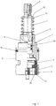
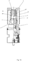
- the valve upper part chosen as an exemplary embodiment has a head piece 1, which is penetrated centrally by a spindle 2 guided radially in it. With the spindle 2, a control disk 3 is positively connected and guided radially in the head piece 1. On the side facing away from the spindle 1 of the control disk 3, an inlet disk 4 is provided in the head piece 1, to which a connection plate 5 connects, which comes to rest with the valve seat - not shown - fitting. Furthermore, the upper valve part is provided with a control sleeve 6 which is penetrated centrally by the spindle 2 and which is biased by a spring 7 against the head piece 1.
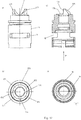
- the head piece 1 consists of a symmetrical hollow body whose two end faces are open. On its side facing the fitting, the head piece 1 has a sleeve-shaped part 14. In the sleeve-shaped part 14 passage windows 11 are provided, which are bounded by longitudinal webs 12. In the embodiment, two limited by longitudinal webs 12 windows 11 are arranged. After introduction of the head piece 1 in a fitting, a collar 13 of the head piece 1 rests on the housing of the fitting. The collar 13 has on its the passage window 11 side facing an annular groove 15 for receiving an O-ring 91. In the sleeve-shaped part 14, a rear turn 16 is arranged inside in the region of the valve seat facing the end.
- a control contour 17 is formed in the head piece 1.
- the control contour 17 has opposite each two rising in opposite directions guide slopes 171, which open into a notch 172.
- two stops 18 are additionally formed in the head piece 1, to counteract the rotation limitation of the spindle 2.
- the spindle 2 is essentially solid. It is on its side facing away from the water supply end outside as outer polygon 21 and provided with a blind hole 22 with internal thread for the attachment of a rotary handle 8. Subsequently, a cylindrical surface 23 is provided on the outside of the spindle 2, to which a square section 24 adjoins. The square section 24 merges into a cylindrical portion 25, with which the spindle 2 is guided radially in the head piece 1 and in which two annular grooves 251 are introduced for receiving rings 92. The O-rings 92 seal the spindle 2 against the head piece 1.
- a boom 27 is integrally formed, which has a substantially rectangular cross-section and on one side beyond the diameter of the cylindrical portion 25 also protrudes.
- the boom 27 is designed such that it in the defined positions “lead 1 fully open” and “lead 2 fully open” rests against the integrally formed within the head piece 1 stop 18 with a side surface.
- a disc 28 is formed, which has a driver 281 on its side facing the fitting.
- a recess 26 is introduced, in which a snap ring 93 is inserted.
- the snap ring 93 serves to abut a washer 94 against which the coil spring 7 is biased against the control sleeve 6.
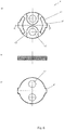
- the control disk 3 is substantially formed as a circular disk, from which a circular cutout 31 is excluded.
- the circular cutout 31 has an angle of approximately 90 °.
- the control disk 3 On its side facing the spindle 2, the control disk 3 has two arcuate shoulders 32 arranged diametrically opposite one another.
- the annular shoulder 32 comprises the driver 281 of the spindle 2.
- Recesses 33 are formed on the shoulders 32, into which the driver 281 engages (see FIG. FIG. 5c) ).
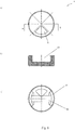
- the inlet disc 4 has on its circumference 2 opposing lugs 41. With the lugs 41, the disc 4 in recesses 19, which are provided for this purpose in the sleeve-shaped part 14 of the head piece 1. The inlet disk 4 is thus arranged rotationally fixed in the head piece 1.
- the inlet disk 4 has two circular, diametrically arranged passage openings 42. The outside are circumferentially of the openings 42 and in Region of the lugs 41 on the armature-side underside of the inlet disc 4 web-like contours 43 formed.
- connection plate 5 is shown in the embodiment of plastic. It also has on its circumference two diametrically opposite lugs 51. With the lugs 51, the connection plate 5 holds in recesses 19, which are provided for this purpose in the sleeve-shaped part 14 of the head piece 1. The connection plate 5 is thus arranged rotationally fixed in the head piece 1.
- the connection disk 5 has two circular, diametrically arranged passage openings 52, which are aligned with the passage openings 42 of the inlet disk 4. In the passage openings 52, a web 521 for receiving a lip seal 95 is integrally formed on the inside. The lip seal 95 is held in the passage opening 52 via an inserted support ring 96.
- the control sleeve 6 is formed substantially hollow cylindrical. It has a substantially square-shaped axial passage 61, which is bounded at its end facing away from the head piece 1 by a collar 62, to which an annular surface 63 connects.
- the ring surface 63 forms together with the collar 62 a receptacle for the coil spring 7.
- On its opposite side of the annular surface 63 are introduced into the control sleeve 6 opposite two each rising in opposite directions inclined guide edges 64, wherein two guide edges 64 at its the head piece. 1 facing maximum form a nose 65, which correspond to a notch 172 of the control contour 17 of the head piece 1.
- the guide edges 64 are formed such that they cooperate with the guide slopes 171 of the control contour 17 of the head piece 1 such that the control sleeve 6 in a relative rotation with respect to the head piece 1 with its guide edges 64 on the guide slopes 171 of the control contour 17 slides along and performs an axial displacement along the spindle 2.
- control sleeve is in the position "completely closed” with their leading edges 64 on the guide slopes 171 of the control contour 17 of the head piece 1 at.
- the square-shaped passage 61 is penetrated by the square section 24 of the spindle 2.
- the coil spring 7 rests on the annular surface 63 surrounding the collar 62 on the control sleeve 6 and is between the control sleeve 6 and the disc 94, which is held axially on the spindle 2 via the snap ring 93, biased.
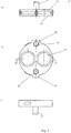
- control contour 17 of the head piece 1 is designed in such a way that it has a respective guide bevel 171 opposite to each of which a flat sliding surface 173 adjoins. Between the guide slope 171 and the sliding surface 173 a notch 172 is arranged in each case.
- the planar sliding surfaces 173 are each bounded by a stop 174, which is arranged at the end of the respective other guide slope 171 (see. FIG. 12 ).
- the control sleeve 6 is formed largely mirror-inverted to the control contour 17 of the head piece 1. It is opposite each arranged a leading edge 62, to which a recessed flat edge 66 connects. In each case, a nose 65 is formed on the respective head of the maximum facing the leading edge 64, which corresponds to a notch 172 of the control contour 17 of the head piece 1 (see. FIG. 11 ). The nose 65 is followed by a stop edge 67, which is aligned substantially orthogonal to the flat edge 66 and which corresponds to the stop 174 of the control contour 17.
- a rotary handle 8 mounted on the spindle 2, a rotary handle 8.
- the rotary handle 8 is largely cup-shaped.
- a sleeve-shaped collar 81 is integrally formed on the inside in the rotary handle 8, on the inside of which a polyhedron is molded and whose free outer edge is provided with locking lugs 82 projecting inwards.
- the rotary handle 8 is mounted on the spindle so that the outer polygon 21 of the spindle 2 is located in the inner polyhedron of the sleeve-like collar 81, wherein the circumferential locking lugs 82 engage in the recess 26 of the spindle 2, whereby the rotary handle 8 is axially fixed to the spindle 2.
- a contact surface 84 is formed to bear the coil spring 7, which is biased between the contact surface 84 and the annular surface 63 of the control sleeve 6 and the control sleeve 6 presses against the control contour 17 of the head piece 1 ,
Description
Die Erfindung betrifft ein Ventiloberteil mit einem Kopfstück, dass von einer Spindel mittig durchsetzt ist, die in dem Kopfstück um ihre Längsachse drehbar gelagert ist und über die ein Ventilkörper bewegbar ist.The invention relates to a valve head with a head piece that is centrally penetrated by a spindle which is rotatably mounted in the head piece about its longitudinal axis and over which a valve body is movable.
Mit Hilfe von Ventiloberteilen wird der Austritt von Medien aus Armaturen gesteuert. Zu diesem Zweck wird das Ventiloberteil mittels seines Kopfstücks in das Gehäuse einer Armatur geschraubt. Auf seine Spindel wird ein Drehgriff oder Hebel gesteckt. Bei bekannten Ventiloberteilen (vgl.
Ventiloberteile werden häufig auch als Mehrwegventil ausgeführt. Hierbei wird jeweils nur einer von mehreren, insbesondere von zwei Zuläufen durch den Ventilkörper freigegeben, sodass wahlweise beispielsweise "nur Kaltwasser" oder "nur Warmwasser" entnommen werden kann. Darüber hinaus ist eine definierte Position "ganz geschlossen" vorgesehen. Zur Reduzierung der abgegebenen Wassermenge, insbesondere auch im Falle der Abgabe von heißem Wasser ist es wünschenswert, dass der Ventilkörper nach dessen Bedienung selbsttätig in die Position "ganz geschlossen" zurückbewegt wird.Valve tops are often designed as a multi-way valve. Here, only one of several, in particular of two Zuläufen is released by the valve body, so that optionally, for example, "only cold water" or "hot water" can be removed. In addition, a defined position "completely closed" is provided. To reduce the amount of water delivered, especially in the case of the delivery of hot water, it is desirable that the valve body is automatically moved back to the position "fully closed" after its operation.
Hier setzt die vorliegende Erfindung an. Der Erfindung liegt die Aufgabe zugrunde, ein Ventiloberteil bereitzustellen, dass nach Betätigung des Ventilkörpers zur Entnahme eines Fluids aus wenigstens einem Zulauf selbsttätig in die Position "ganz geschlossen" verfährt. Gemäß der Erfindung wird diese Aufgabe durch ein Ventiloberteil mit den Merkmalen des kennzeichnenden Teils des Patentanspruchs 1 gelöst.This is where the present invention begins. The invention has for its object to provide a valve bonnet that after actuation of the valve body to remove a fluid from at least one inlet automatically moves into the "fully closed" position. According to the invention, this object is achieved by a valve bonnet with the features of the characterizing part of
Mit der Erfindung ist ein Ventiloberteil geschaffen, dass nach Betätigung des Ventilkörpers zur Entnahme eines Fluids aus zumindest einem Zulauf selbsttätig in die Position "ganz geschlossen" verfährt.With the invention, a valve top is created that moves automatically after actuation of the valve body for removing a fluid from at least one inlet in the position "completely closed".
In Weiterbildung der Erfindung ist die Steuerhülse mit der Spindel über einen Formschluss axial verschiebbar verbunden. Hierdurch ist ein Verschieben der Steuerhülse entlang der Steuerkontur des Kopfstücks bei gleichzeitiger Übertragung eines Drehmoments auf die Spindel ermöglicht.In a further development of the invention, the control sleeve is connected axially displaceably to the spindle via a positive connection. As a result, a displacement of the control sleeve along the control contour of the head piece is enabled while transmitting torque to the spindle.
In Ausgestaltung der Erfindung weist die Steuerhülse eine unrunde, insbesondere mehrkantförmige oder auch polygonförmige axiale Durchführung auf, durch die ein an der Spindel angeordneter unrunder, insbesondere mehrkantförmiger oder auch polygoner Abschnitt hindurch tritt. Dabei ist die Steuerhülse bevorzugt über eine Feder gegen das Kopfstück vorgespannt. Hierdurch ist ein kontinuierlicher Kontakt zwischen Steuerhülse und Steuerkontur des Kopfstücks erzielt.In an embodiment of the invention, the control sleeve on a non-circular, in particular polygonal or polygonal axial passage through which passes a arranged on the spindle non-circular, in particular polygonal or polygonal section passes. In this case, the control sleeve is preferably biased by a spring against the head piece. As a result, a continuous contact between the control sleeve and the control contour of the head piece is achieved.
In Weiterbildung der Erfindung weist die Steuerhülse wenigstens eine schräge Führungskante auf, die an einer Führungsschräge der Steuerkontur anliegt, derart, dass bei Drehung der Steuerhülse in eine definierte Richtung eine axiale Verschiebung der Steuerhülse entgegen der Vorspannung der Feder erfolgt. Hierdurch ist eine Erhöhung der Rückstellkraft der Feder bei Drehung der Spindel und damit der Steuerhülse erzielt, welche im Anschluss an die Betätigung nach Loslassen der Spindel eine Rückstellung der Position der Steuerhülse und damit der Spindel in die Ausgangsposition "ganz geschlossen" bewirkt. Unter einer "schrägen Führungskante" ist vorliegend eine eine Auflagefläche aufweisende Kante zu verstehen, die in ihrem Verlauf eine Steigung aufweist, wobei die Steigung nicht linear erfolgen muss. Der Begriff "Führungskante" ist im Folgenden mit dem Begriff "Führungsschräge" gleich zu setzen. Die unterschiedlichen Begriffe werden lediglich zur besseren Zuordnung zur Steuerkontur bzw. zur Steuerhülse gewählt.In a further development of the invention, the control sleeve has at least one oblique leading edge, which rests against a guide bevel of the control contour, such that upon rotation of the control sleeve in a defined direction, an axial displacement of the control sleeve against the bias of the spring. As a result, an increase in the restoring force of the spring upon rotation of the spindle and thus the control sleeve is achieved, which causes a reset of the position of the control sleeve and thus the spindle in the starting position "fully closed" following actuation after releasing the spindle. In the present case, an "inclined leading edge" is to be understood as an edge having a bearing surface which has a gradient in its course, wherein the gradient does not have to be linear. The term "leading edge" is to be equated below with the term "guide slope". The different terms are chosen only for better allocation to the control contour or the control sleeve.
In Weiterbildung der Erfindung weist die Steuerhülse wenigstens zwei in entgegengesetzter Richtung ansteigende schräge Führungskanten auf, die an zwei in entgegengesetzten Richtungen steigende Führungsschrägen der Steuerkontur anliegen, derart, dass bei Rotation der Steuerhülse in eine beliebige Richtung eine axiale Verschiebung der Steuerhülse entgegen der Vorspannung der Feder bewirkt ist. Hierdurch ist eine selbsttätige Rückstellung des Ventilkörpers in die Position "ganz geschlossen" aus beiden Öffnungspositionen (beispielsweise "nur Kaltwasser" bzw. "nur Warmwasser") bewirkt.In a further development of the invention, the control sleeve has at least two sloping leading edges rising in the opposite direction, which abut against two increasing in opposite directions guide slopes of the control contour, such that upon rotation of the control sleeve in any direction an axial displacement of the control sleeve against the bias of the spring is effected. As a result, an automatic reset of the valve body in the position "completely closed" from both opening positions (for example, "cold water only" or "only hot water") causes.
In einer anderen Ausgestaltung der Erfindung weist die Steuerkontur benachbart der wenigstens einen Führungsschräge eine ebene Gleitfläche auf. Hierdurch ist bei Drehung der Spindel in Richtung der Führungsschräge eine anschließende selbsttätige Rückstellung in die Position "ganz geschlossen" erzielt, wobei eine Drehung der Spindel in die entgegengesetzte Richtung ohne selbsttätige Rückstellung erfolgt. Hierdurch ist beispielsweise bei der Entnahme von Heißwasser eine automatische Rückstellung des Ventilkörpers in die Position "ganz geschlossen" und bei der Entnahme von Kaltwasser eine Einstellung einer kontinuierlichen, dauerhaften Abgabemenge ermöglicht. Bevorzugt ist die ebene Gleitfläche an einer Seite durch einen Anschlag begrenzt, der mit einem an der Steuerhülse angeordneten Anschlag zusammenwirkt.In another embodiment of the invention, the control contour adjacent to the at least one guide slope on a flat sliding surface. As a result, upon rotation of the spindle in the direction of the guide slope, a subsequent automatic return to the "fully closed" position is achieved, with rotation of the spindle in the opposite direction without automatic resetting. As a result, for example, when removing hot water automatic reset of the valve body in the position "completely closed" and allows for the removal of cold water, a setting of a continuous, permanent discharge amount. Preferably, the planar sliding surface is bounded on one side by a stop which cooperates with a stop arranged on the control sleeve.
In Weiterbildung der Erfindung mündet die wenigstens eine Führungsschräge der Steuerkontur in eine Einkerbung, in die in Grundstellung des Ventilkörpers eine an ihren dem Kopfstück zugewandten Ende der schrägen Führungskante angeordnete Nase eingreift. Hierdurch ist eine mechanische Arretierung der Steuerhülse und damit auch der Spindel in der Position "ganz geschlossen" erzielt.In a further development of the invention, the at least one guide slope of the control contour opens into a notch into which, in the basic position of the valve body, a nose arranged at its end facing the headpiece of the oblique leading edge engages. As a result, a mechanical locking of the control sleeve and thus also the spindle in the position "completely closed" is achieved.
In weiterer Ausgestaltung der Erfindung sind außerhalb der Steuerkontur innerhalb des Kopfstücks zwei Anschlagflächen angeordnet, die mit einem an der Spindel angeordneten Vorsprung derart korrespondieren, dass eine beidseitige Drehbegrenzung der Spindel bewirkt ist. Hierdurch ist ein definierter Drehbereich der Spindel innerhalb des Kopfstücks erzielt.In a further embodiment of the invention, two stop surfaces are arranged outside of the control contour within the head piece, which correspond with a projection arranged on the spindle such that a bilateral Rotation limitation of the spindle is effected. As a result, a defined range of rotation of the spindle is achieved within the head piece.
In Ausgestaltung der Erfindung ist an der Spindel eine radial zumindest bereichsweise umlaufende Anschlagkante angeordnet, an der die Feder mit ihrem dem Kopfstück abgewandten Ende anliegt. Die Anschlagkante kann beispielsweise durch einen in einer Nut der Spindel angebrachten Sprengring, einen an die Spindel angeformten Absatz oder auch durch eine an einem auf der Spindel montierten Drehgriff befindliche Anschlagfläche gebildet sein. Vorteilhaft ist die Anschlagkante durch eine Gewindemutter gebildet, die auf ein an der Spindel angeordnetes Außengewinde aufgeschraubt ist. Hierdurch ist eine Einstellung der Vorspannkraft der anliegenden Feder durch axiale Bewegung der Gewindemutter ermöglicht.In an embodiment of the invention, a radially at least partially circumferential stop edge is arranged on the spindle, against which the spring abuts with its end facing away from the head piece. The stop edge can be formed for example by a mounted in a groove of the spindle snap ring, an integrally formed on the spindle shoulder or by a stopper mounted on a spindle mounted on the rotary stop surface. Advantageously, the stop edge is formed by a threaded nut which is screwed onto an external thread arranged on the spindle. As a result, an adjustment of the biasing force of the adjacent spring is made possible by axial movement of the threaded nut.
Andere Weiterbildungen und Ausgestaltungen der Erfindung sind in den übrigen Unteransprüchen angegeben. Ausführungsbeispiele der Erfindung sind in den Zeichnungen dargestellt und werden nachfolgend im Einzelnen beschrieben. Es zeigen:
Figur 1- die schematische Darstellung eines Ventiloberteils im Teilschnitt;
Figur 2- die Darstellung der Spindel des Ventiloberteils aus
Figur 1- a) in Seitenansicht;
- b) in der Draufsicht;
Figur 3- die Darstellung der Steuerhülse des Ventiloberteils aus
Figur 1- a) in der Ansicht von unten;
- b) in Seitenansicht im Teilschnitt
- c) in der Draufsicht;
Figur 4- die Darstellung des Kopfstücks des Ventiloberteils aus
Figur 1- a) in Seitenansicht;
- b) in der Draufsicht;
- c) um 90° verdreht in Schnittdarstellung;
- d) in Querschnittsansicht von unten;
Figur 5- die Darstellung der Steuerscheibe des Ventiloberteils aus
Figur 1- a) in der Ansicht von unten;
- b) im Axialschnitt;
- c) in der Draufsicht;
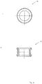
Figur 6- die Darstellung der Einlassscheibe des Ventiloberteils aus
Figur 1 - a) in der Draufsicht;
- b) im Querschnitt
- c) in der Ansicht von unten
Figur 7- die Darstellung der Anschlussscheibe des Ventiloberteils aus
Figur 1 - a) im Querschnitt;
- b) in der Ansicht von unten;
- c) in der Seitenansicht;
Figur 8- die Darstellung der Lippendichtungen der Anschlussscheibe des Ventiloberteils aus
Figur 1 - a) in der Draufsicht;
- b) im Querschnitt;
- Figur 9
- die Darstellung des Stützrings der Anschlussscheibe des Ventiloberteils aus
Figur 1 - a) im Querschnitt;
- b) in der Draufsicht;
- Figur 10
- die schematische Darstellung eines Ventiloberteils in einer weiteren Ausführungsform;
Figur 11- die Darstellung der Steuerhülse des Ventiloberteils aus
Figur 10 - a) in der Ansicht von unten;
- b) in der Seitenansicht;
- c) in der Draufsicht;
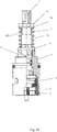
Figur 12- die Darstellung des Kopfteils des Ventiloberteils aus
Figur 10 - a) in der Seitenansicht;
- b) in der Draufsicht;
- c) um 90° verdreht im Querschnitt;
- d) in einer Querschnittsansicht von unten
Figur 13- die schematische Darstellung eines Ventiloberteils in einer dritten Ausführungsform.
- FIG. 1
- the schematic representation of a valve shell in partial section;
- FIG. 2
- the representation of the spindle of the valve top part
FIG. 1 - a) in side view;
- b) in plan view;
- FIG. 3
- the representation of the control sleeve of the valve bonnet
FIG. 1 - a) in the view from below;
- b) in side view in partial section
- c) in plan view;
- FIG. 4
- the representation of the head piece of the valve bonnet
FIG. 1 - a) in side view;
- b) in plan view;
- c) rotated by 90 ° in a sectional view;
- d) in cross-sectional view from below;
- FIG. 5
- the representation of the control disk of the valve bonnet
FIG. 1 - a) in the view from below;
- b) in axial section;
- c) in plan view;
- FIG. 6
- the representation of the inlet disc of the valve bonnet
FIG. 1 - a) in plan view;
- b) in cross-section
- c) in the view from below
- FIG. 7
- the representation of the connection plate of the valve bonnet
FIG. 1 - a) in cross-section;
- b) in the view from below;
- c) in side view;
- FIG. 8
- the representation of the lip seals of the connection disc of the valve bonnet
FIG. 1 - a) in plan view;
- b) in cross section;
- FIG. 9
- the representation of the support ring of the connection plate of the valve bonnet
FIG. 1 - a) in cross-section;
- b) in plan view;
- FIG. 10
- the schematic representation of a valve bonnet in a further embodiment;
- FIG. 11
- the representation of the control sleeve of the valve bonnet
FIG. 10 - a) in the view from below;
- b) in side view;
- c) in plan view;
- FIG. 12
- the representation of the head portion of the valve bonnet
FIG. 10 - a) in side view;
- b) in plan view;
- c) twisted by 90 ° in cross section;
- d) in a cross-sectional view from below
- FIG. 13
- the schematic representation of a valve upper part in a third embodiment.
Das als Ausführungsbeispiel gewählte Ventiloberteil weist ein Kopfstück 1 auf, das von einer in ihm radial geführten Spindel 2 mittig durchsetzt ist. Mit der Spindel 2 ist eine Steuerscheibe 3 formschlüssig verbunden und im Kopfstück 1 radial geführt. An dem der Spindel 1 abgewandten Seite der Steuerscheibe 3 ist eine Einlassscheibe 4 in dem Kopfstück 1 vorgesehen, an die sich eine Anschlussscheibe 5 anschließt, die mit dem Ventilsitz einer - nicht dargestellten - Armatur zur Anlage kommt. Weiterhin ist das Ventiloberteil mit einer Steuerhülse 6 versehen, die von der Spindel 2 mittig durchsetzt ist und die über eine Feder 7 gegen das Kopfstück 1 vorgespannt ist.The valve upper part chosen as an exemplary embodiment has a
Das Kopfstück 1 besteht aus einem symmetrischen Hohlkörper, dessen beide Stirnflächen offen sind. Auf seiner der Armatur zugewandten Seite weist das Kopfstück 1 einen hülsenförmigen Teil 14 auf. In dem hülsenförmigen Teil 14 sind Durchtrittsfenster 11 vorgesehen, die von Längsstegen 12 begrenzt sind. Im Ausführungsbeispiel sind zwei durch Längsstege 12 begrenzte Fenster 11 angeordnet. Nach dem Einbringen des Kopfstücks 1 in eine Armatur liegt ein Bund 13 des Kopfstücks 1 auf dem Gehäuse der Armatur auf. Der Bund 13 weist auf seiner dem Durchtrittsfenster 11 zugewandten Seite eine Ringnut 15 zur Aufnahme eines O-Rings 91 auf. In dem hülsenförmigen Teil 14 ist innen im Bereich des dem Ventilsitz zugewandten Ende eine Hinterdrehung 16 angeordnet.The
An seinem dem Durchtrittsfenster 11 entgegengesetzten Ende ist in das Kopfstück 1 eine Steuerkontur 17 angeformt. Die Steuerkontur 17 weist gegenüberliegend jeweils zwei in entgegengesetzte Richtungen ansteigende Führungsschrägen 171 auf, die in eine Einkerbung 172 münden. Im Bereich des Bundes 13 sind weiterhin in dem Kopfstück 1 innen gegenüberliegend zwei Anschläge 18 zur Drehbegrenzung der Spindel 2 angeformt.At its end opposite the
Die Spindel 2 ist im Wesentlichen massiv ausgeführt. Sie ist an ihrer dem Wasserzulauf abgewandten Stirnseite außen als Außenvielkant 21 ausgeführt und mit einem Sackloch 22 mit Innengewinde für die Befestigung eines Drehgriffs 8 versehen. Anschließend ist außen an der Spindel 2 eine Zylinderfläche 23 vorgesehen, an die sich ein Vierkantabschnitt 24 anschließt. Der Vierkantabschnitt 24 geht in einen zylindrischen Abschnitt 25 über, mit dem die Spindel 2 in dem Kopfstück 1 radial geführt ist und in dem zwei Ringnuten 251 zur Aufnahme von Ringen 92 eingebracht sind. Die O-Ringe 92 dichten die Spindel 2 gegen das Kopfstück 1 ab.The
An den zylindrischen Abschnitt 25 ist axial ein Ausleger 27 angeformt, der im Wesentlichen einen rechteckigen Querschnitt aufweist und an einer Seite über den Durchmesser des zylindrischen Abschnitts 25 hinaus ragt. Der Ausleger 27 ist derart ausgebildet, dass er in den definierten Positionen "Zuleitung 1 vollständig geöffnet" und "Zuleitung 2 vollständig geöffnet" an dem innerhalb des Kopfstücks 1 angeformten Anschlag 18 mit einer Seitenfläche anliegt. An den Ausleger 27 ist eine Scheibe 28 angeformt, die auf ihrer der Armatur zugewandten Seite einen Mitnehmer 281 aufweist.On the
Zwischen der Zylinderfläche 23 und dem Außenvielkant 21 ist ein Einstich 26 eingebracht, in dem ein Sprengring 93 eingelegt ist. Der Sprengring 93 dient der Anlage einer Scheibe 94, an der die Schraubenfeder 7 anliegt, die gegen die Steuerhülse 6 vorgespannt ist.Between the
Die Steuerscheibe 3 ist im Wesentlichen als kreisrunde Scheibe ausgebildet, aus der ein Kreisausschnitt 31 ausgenommen ist. Der Kreisausschnitt 31 weist im Ausführungsbeispiel einen Winkel von ca. 90° auf Auf ihrer der Spindel 2 zugewandten Seite weist die Steuerscheibe 3 zwei diametral zueinander angeordnete bogenförmige Absätze 32 auf. Der ringförmige Absatz 32 umfasst im montierten Zustand den Mitnehmer 281 der Spindel 2. An den Absätzen 32 sind Ausnehmungen 33 ausgebildet, in die der Mitnehmer 281 eingreift (vgl.
Die Einlassscheibe 4 weist auf ihrem Umfang 2 sich gegenüberliegende Nasen 41 auf. Mit den Nasen 41 fasst die Scheibe 4 in Ausnehmungen 19, die hierzu in dem hülsenförmigen Teil 14 des Kopfstücks 1 vorgesehen sind. Die Einlassscheibe 4 ist damit drehfest in dem Kopfstück 1 angeordnet. Die Einlassscheibe 4 weist zwei kreisrunde, diametral zueinander angeordnete Durchtrittsöffnungen 42 auf. Außen sind umlaufend der Durchtrittsöffnungen 42 sowie im Bereich der Nasen 41 auf der armaturseitigen Unterseite der Einlassscheibe 4 stegartige Konturen 43 angeformt.The
Die Anschlussscheibe 5 ist im Ausführungsbeispiel aus Kunststoff dargestellt. Sie weist auf ihrem Umfang ebenfalls zwei sich diametral gegenüberliegende Nasen 51 auf. Mit den Nasen 51 fasst die Anschlussscheibe 5 in Ausnehmungen 19, die hierzu in dem hülsenförmigen Teil 14 des Kopfstücks 1 vorgesehen sind. Die Anschlussscheibe 5 ist damit drehfest in dem Kopfstück 1 angeordnet. Die Anschlussscheibe 5 weist zwei kreisrunde, diametral zueinander angeordnete Durchtrittsöffnungen 52 auf, welche mit den Durchtrittsöffnungen 42 der Einlassscheibe 4 fluchten. In den Durchtrittsöffnungen 52 ist innen umlaufend jeweils ein Steg 521 zur Aufnahme einer Lippendichtung 95 angeformt. Die Lippendichtung 95 ist über einen eingebrachten Stützring 96 in der Durchtrittsöffnung 52 gehalten. In montiertem Zustand liegen die Lippen der Lippendichtung 95 dichtend gegen die Durchlassscheibe 4 sowie gegen den - nicht dargestellten - Armatursitz an. Weiterhin sind außen auf der armaturseitigen Unterseite der Anschlussscheibe 5 gegenüberliegend zwei zylinderförmige Stifte 53 angeformt. Die Stifte 53 dienen der Positionierung des Ventiloberteils in der - nicht dargestellten - Armatur.The
Die Steuerhülse 6 ist im Wesentlichen hohlzylindrisch ausgebildet. Sie weist eine im Wesentlichen vierkantförmige axiale Durchführung 61 auf, die an ihrem den Kopfstück 1 abgewandten Ende von einem Kragen 62 begrenzt ist, an den sich eine Ringfläche 63 anschließt. Die Ringfläche 63 bildet gemeinsam mit dem Kragen 62 eine Aufnahme für die Schraubenfeder 7. An ihrer der Ringfläche 63 gegenüberliegenden Unterseite sind in die Steuerhülse 6 gegenüberliegend jeweils zwei in entgegengesetzte Richtungen ansteigende schräge Führungskanten 64 eingebracht, wobei jeweils zwei Führungskanten 64 an ihrem dem Kopfstück 1 zugewandten Maximum eine Nase 65 ausbilden, die mit einer Einkerbung 172 der Steuerkontur 17 des Kopfstücks 1 korrespondieren. Die Führungskanten 64 sind derart ausgebildet, dass sie mit den Führungsschrägen 171 der Steuerkontur 17 des Kopfstücks 1 derart zusammenwirken, dass die Steuerhülse 6 bei einer relativen Drehung gegenüber dem Kopfstück 1 mit ihren Führungskanten 64 an den Führungsschrägen 171 der Steuerkontur 17 entlang gleitet und eine axiale Verschiebung entlang der Spindel 2 vollzieht.The
Die so ausgebildete Steuerhülse liegt in der Position "ganz geschlossen" mit ihren Führungskanten 64 an den Führungsschrägen 171 der Steuerkontur 17 des Kopfstücks 1 an. Dabei ist die vierkantförmige Durchführung 61 von dem Vierkantabschnitt 24 der Spindel 2 durchdrungen. Die Schraubenfeder 7 liegt auf der Ringfläche 63 den Kragen 62 umgebend an der Steuerhülse 6 an und ist zwischen Steuerhülse 6 und der Scheibe 94, die über den Sprengring 93 an der Spindel 2 axial gehalten ist, vorgespannt.The thus formed control sleeve is in the position "completely closed" with their leading
Im Ausführungsbeispiel gemäß
Die Steuerhülse 6 ist weitgehend spiegelgleich zur Steuerkontur 17 des Kopfstücks 1 ausgebildet. Es ist gegenüberliegend jeweils eine Führungskante 62 angeordnet, an die sich eine zurückversetzte ebene Kante 66 anschließt. Dabei ist an dem jeweiligen dem Kopfstück zugewandten Maximum der Führungskanten 64 jeweils eine Nase 65 ausgebildet, die mit einer Einkerbung 172 der Steuerkontur 17 des Kopfstücks 1 korrespondiert (vgl.
Weiterhin ist im Ausführungsbeispiel gemäß
Im Ausführungsbeispiel gemäß
Claims (12)
- Valve top having a head part (1) through the centre of which runs a spindle (2) that is mounted rotatably about its longitudinal axis in the head part (1) and by means of which a valve body that is formed by a control disk (3) that is positively connected to the spindle (2) and can be rotated by means of this spindle (2) can be actuated relative to an inlet disk (4) co-rotatably arranged in the head part (1), characterised in that the spindle (2) is provided with a control sleeve (6) that coacts in such a way with a control profile (17) arranged on the head part (1) that after being actuated in a defined direction by the spindle (2) the valve body is caused to return automatically to its home position.
- Valve top in accordance with claim 1, characterised in that the control sleeve (6) is axially displaceably connected to the spindle (2) by a positive connection.
- Valve top in accordance with claim 2, characterised in that the control sleeve (6) has a non-round, preferably polygonal axial opening (61) through which passes a non-round, preferably polygonal section (24) arranged on the spindle (2).
- Valve top in accordance with claim 2 or claim 3, characterised in that the control sleeve (6) is pre-tensioned against the head part (1) by a spring (7).
- Valve top in accordance with claim 4, characterised in that the control sleeve (6) has at least one oblique guiding edge (64) which lies against a guide bevel (171) of the control contour (17) in such a way that when the control sleeve (6) is rotated in a defined direction, the control sleeve (6) moves axially against the pretension of the spring (7).
- Valve top in accordance with claim 5, characterised in that the control sleeve (6) has at least two oblique guiding edges (64) sloping in opposite directions which lie against two guide bevels (171) of the control profile (17) of the guide sleeve (5) which slope in opposite directions, in such a way that when the control sleeve (6) is rotated in any direction, the control sleeve (6) moves axially against the pretension of the spring (7).
- Valve top in accordance with claim 5, characterised in that the control profile (17) adjacent to the at least one guide bevel (171) has a flat sliding surface (173).
- Valve top in accordance with claim 7, characterised in that the flat sliding surface (173) is delimited on one side by a stop (174) which interacts with a stop (67) arranged on the control sleeve (6).
- Valve top in accordance with any of the claims 5 to 8, characterised in that the at least one guide bevel (171) of the control profile (17) opens into a notch (172), into which a tappet (65) arranged at the end of the oblique guiding edge (64) facing the head part (1) engages when the valve body is in its starting position.
- Valve profile in accordance with any one of the foregoing claims, characterised in that outside the control profile (17) and inside the head part (1) two stops (18) that fit with a projecting member (27) that are arranged on the spindle (2) in such a way that rotation of the spindle (2) is limited on both sides.
- Valve top in accordance with any one of claims 4 to 10, characterised in that a radially at least partly circumferential stop edge against which lies the spring (7) with its end oriented away from the head part (1) is arranged on the spindle (2).
- Valve top in accordance with claim 11, characterised in that the stop edge is formed by a nut (97) that is screwed onto an external thread (252) arranged on the spindle (2).
Priority Applications (4)
| Application Number | Priority Date | Filing Date | Title |
|---|---|---|---|
| ES13177468.9T ES2672502T3 (en) | 2013-07-22 | 2013-07-22 | Upper valve |
| HUE13177468A HUE038207T2 (en) | 2013-07-22 | 2013-07-22 | Valve top |
| TR2018/08281T TR201808281T4 (en) | 2013-07-22 | 2013-07-22 | Upper part of the valve. |
| EP13177468.9A EP2829779B1 (en) | 2013-07-22 | 2013-07-22 | Valve top |
Applications Claiming Priority (1)
| Application Number | Priority Date | Filing Date | Title |
|---|---|---|---|
| EP13177468.9A EP2829779B1 (en) | 2013-07-22 | 2013-07-22 | Valve top |
Publications (2)
| Publication Number | Publication Date |
|---|---|
| EP2829779A1 EP2829779A1 (en) | 2015-01-28 |
| EP2829779B1 true EP2829779B1 (en) | 2018-03-21 |
Family
ID=48803461
Family Applications (1)
| Application Number | Title | Priority Date | Filing Date |
|---|---|---|---|
| EP13177468.9A Active EP2829779B1 (en) | 2013-07-22 | 2013-07-22 | Valve top |
Country Status (4)
| Country | Link |
|---|---|
| EP (1) | EP2829779B1 (en) |
| ES (1) | ES2672502T3 (en) |
| HU (1) | HUE038207T2 (en) |
| TR (1) | TR201808281T4 (en) |
Family Cites Families (6)
| Publication number | Priority date | Publication date | Assignee | Title |
|---|---|---|---|---|
| US1365694A (en) * | 1919-07-08 | 1921-01-18 | George R Jernstedt | Valve construction |
| DE693636C (en) * | 1936-04-25 | 1940-07-16 | Auergesellschaft Akt Ges | Manually operated auxiliary air valve on high altitude breathing apparatus |
| US2606450A (en) * | 1949-12-08 | 1952-08-12 | Crane Co | Valve actuating mechanism |
| US3780758A (en) * | 1972-11-15 | 1973-12-25 | Wolverine Brass Works Ind Inc | Non-metallic cartridge valve |
| DE3207895C2 (en) | 1982-03-05 | 1983-12-29 | Fa. Otto Flühs, 5880 Lüdenscheid | Upper valve part for sanitary fittings |
| US5103857A (en) * | 1989-10-18 | 1992-04-14 | Kohler Co. | Self closing valve assembly |
-
2013
- 2013-07-22 ES ES13177468.9T patent/ES2672502T3/en active Active
- 2013-07-22 TR TR2018/08281T patent/TR201808281T4/en unknown
- 2013-07-22 HU HUE13177468A patent/HUE038207T2/en unknown
- 2013-07-22 EP EP13177468.9A patent/EP2829779B1/en active Active
Non-Patent Citations (1)
| Title |
|---|
| None * |
Also Published As
| Publication number | Publication date |
|---|---|
| HUE038207T2 (en) | 2018-10-29 |
| EP2829779A1 (en) | 2015-01-28 |
| ES2672502T3 (en) | 2018-06-14 |
| TR201808281T4 (en) | 2018-07-23 |
Similar Documents
| Publication | Publication Date | Title |
|---|---|---|
| EP3221621B1 (en) | Valve top | |
| EP2941579B1 (en) | Valve top | |
| EP3420430B1 (en) | Thermostat mixing valve | |
| EP1696158A1 (en) | Valve head | |
| DE102006025965B4 (en) | Gas cylinder valve assembly | |
| EP3062002B1 (en) | Upper part of a valve | |
| EP1462692B1 (en) | Valve head | |
| EP2829779B1 (en) | Valve top | |
| EP3591271B1 (en) | Upper part of a valve | |
| DE102006027558B4 (en) | Valve top | |
| EP3265704B1 (en) | Valve bonnet for fittings | |
| EP2549156B1 (en) | Valve top for fittings | |
| DE202011103480U1 (en) | Valve head for valves | |
| EP3062001B1 (en) | Upper part of a valve | |
| EP2696117B1 (en) | Valve top | |
| EP4137722B1 (en) | Valve cartridge | |
| DE2642641C3 (en) | Temporary protective cap for attachment to a shut-off valve | |
| EP3702651B1 (en) | Valve top section for sanitary fittings | |
| WO2017042077A1 (en) | Bidet shower | |
| DE202018103777U1 (en) | Valve top | |
| DE202013103306U1 (en) | Absperrventiloberteil | |
| DE202008001495U1 (en) | Valve head for valves | |
| EP3693643A1 (en) | Valve top section for sanitary fittings | |
| EP3112540A1 (en) | Upper part of a valve | |
| EP2829776A1 (en) | Shut-off valve top |
Legal Events
| Date | Code | Title | Description |
|---|---|---|---|
| 17P | Request for examination filed |
Effective date: 20140730 |
|
| AK | Designated contracting states |
Kind code of ref document: A1 Designated state(s): AL AT BE BG CH CY CZ DE DK EE ES FI FR GB GR HR HU IE IS IT LI LT LU LV MC MK MT NL NO PL PT RO RS SE SI SK SM TR |
|
| AX | Request for extension of the european patent |
Extension state: BA ME |
|
| PUAI | Public reference made under article 153(3) epc to a published international application that has entered the european phase |
Free format text: ORIGINAL CODE: 0009012 |
|
| RIC1 | Information provided on ipc code assigned before grant |
Ipc: F16K 21/04 20060101ALI20170714BHEP Ipc: F16K 11/074 20060101ALI20170714BHEP Ipc: F16K 31/524 20060101AFI20170714BHEP |
|
| GRAP | Despatch of communication of intention to grant a patent |
Free format text: ORIGINAL CODE: EPIDOSNIGR1 |
|
| INTG | Intention to grant announced |
Effective date: 20171120 |
|
| GRAS | Grant fee paid |
Free format text: ORIGINAL CODE: EPIDOSNIGR3 |
|
| GRAA | (expected) grant |
Free format text: ORIGINAL CODE: 0009210 |
|
| AK | Designated contracting states |
Kind code of ref document: B1 Designated state(s): AL AT BE BG CH CY CZ DE DK EE ES FI FR GB GR HR HU IE IS IT LI LT LU LV MC MK MT NL NO PL PT RO RS SE SI SK SM TR |
|
| REG | Reference to a national code |
Ref country code: GB Ref legal event code: FG4D Free format text: NOT ENGLISH |
|
| REG | Reference to a national code |
Ref country code: CH Ref legal event code: EP |
|
| REG | Reference to a national code |
Ref country code: AT Ref legal event code: REF Ref document number: 981474 Country of ref document: AT Kind code of ref document: T Effective date: 20180415 |
|
| REG | Reference to a national code |
Ref country code: IE Ref legal event code: FG4D Free format text: LANGUAGE OF EP DOCUMENT: GERMAN |
|
| REG | Reference to a national code |
Ref country code: DE Ref legal event code: R096 Ref document number: 502013009694 Country of ref document: DE |
|
| REG | Reference to a national code |
Ref country code: ES Ref legal event code: FG2A Ref document number: 2672502 Country of ref document: ES Kind code of ref document: T3 Effective date: 20180614 |
|
| REG | Reference to a national code |
Ref country code: NL Ref legal event code: MP Effective date: 20180321 |
|
| PG25 | Lapsed in a contracting state [announced via postgrant information from national office to epo] |
Ref country code: NO Free format text: LAPSE BECAUSE OF FAILURE TO SUBMIT A TRANSLATION OF THE DESCRIPTION OR TO PAY THE FEE WITHIN THE PRESCRIBED TIME-LIMIT Effective date: 20180621 Ref country code: HR Free format text: LAPSE BECAUSE OF FAILURE TO SUBMIT A TRANSLATION OF THE DESCRIPTION OR TO PAY THE FEE WITHIN THE PRESCRIBED TIME-LIMIT Effective date: 20180321 Ref country code: CY Free format text: LAPSE BECAUSE OF FAILURE TO SUBMIT A TRANSLATION OF THE DESCRIPTION OR TO PAY THE FEE WITHIN THE PRESCRIBED TIME-LIMIT Effective date: 20180321 Ref country code: LT Free format text: LAPSE BECAUSE OF FAILURE TO SUBMIT A TRANSLATION OF THE DESCRIPTION OR TO PAY THE FEE WITHIN THE PRESCRIBED TIME-LIMIT Effective date: 20180321 |
|
| REG | Reference to a national code |
Ref country code: LT Ref legal event code: MG4D |
|
| PG25 | Lapsed in a contracting state [announced via postgrant information from national office to epo] |
Ref country code: BG Free format text: LAPSE BECAUSE OF FAILURE TO SUBMIT A TRANSLATION OF THE DESCRIPTION OR TO PAY THE FEE WITHIN THE PRESCRIBED TIME-LIMIT Effective date: 20180621 Ref country code: GR Free format text: LAPSE BECAUSE OF FAILURE TO SUBMIT A TRANSLATION OF THE DESCRIPTION OR TO PAY THE FEE WITHIN THE PRESCRIBED TIME-LIMIT Effective date: 20180622 Ref country code: RS Free format text: LAPSE BECAUSE OF FAILURE TO SUBMIT A TRANSLATION OF THE DESCRIPTION OR TO PAY THE FEE WITHIN THE PRESCRIBED TIME-LIMIT Effective date: 20180321 Ref country code: SE Free format text: LAPSE BECAUSE OF FAILURE TO SUBMIT A TRANSLATION OF THE DESCRIPTION OR TO PAY THE FEE WITHIN THE PRESCRIBED TIME-LIMIT Effective date: 20180321 Ref country code: LV Free format text: LAPSE BECAUSE OF FAILURE TO SUBMIT A TRANSLATION OF THE DESCRIPTION OR TO PAY THE FEE WITHIN THE PRESCRIBED TIME-LIMIT Effective date: 20180321 |
|
| PG25 | Lapsed in a contracting state [announced via postgrant information from national office to epo] |
Ref country code: MT Free format text: LAPSE BECAUSE OF FAILURE TO SUBMIT A TRANSLATION OF THE DESCRIPTION OR TO PAY THE FEE WITHIN THE PRESCRIBED TIME-LIMIT Effective date: 20180321 |
|
| REG | Reference to a national code |
Ref country code: HU Ref legal event code: AG4A Ref document number: E038207 Country of ref document: HU |
|
| PG25 | Lapsed in a contracting state [announced via postgrant information from national office to epo] |
Ref country code: PL Free format text: LAPSE BECAUSE OF FAILURE TO SUBMIT A TRANSLATION OF THE DESCRIPTION OR TO PAY THE FEE WITHIN THE PRESCRIBED TIME-LIMIT Effective date: 20180321 Ref country code: EE Free format text: LAPSE BECAUSE OF FAILURE TO SUBMIT A TRANSLATION OF THE DESCRIPTION OR TO PAY THE FEE WITHIN THE PRESCRIBED TIME-LIMIT Effective date: 20180321 Ref country code: NL Free format text: LAPSE BECAUSE OF FAILURE TO SUBMIT A TRANSLATION OF THE DESCRIPTION OR TO PAY THE FEE WITHIN THE PRESCRIBED TIME-LIMIT Effective date: 20180321 Ref country code: RO Free format text: LAPSE BECAUSE OF FAILURE TO SUBMIT A TRANSLATION OF THE DESCRIPTION OR TO PAY THE FEE WITHIN THE PRESCRIBED TIME-LIMIT Effective date: 20180321 Ref country code: AL Free format text: LAPSE BECAUSE OF FAILURE TO SUBMIT A TRANSLATION OF THE DESCRIPTION OR TO PAY THE FEE WITHIN THE PRESCRIBED TIME-LIMIT Effective date: 20180321 |
|
| PG25 | Lapsed in a contracting state [announced via postgrant information from national office to epo] |
Ref country code: SK Free format text: LAPSE BECAUSE OF FAILURE TO SUBMIT A TRANSLATION OF THE DESCRIPTION OR TO PAY THE FEE WITHIN THE PRESCRIBED TIME-LIMIT Effective date: 20180321 Ref country code: SM Free format text: LAPSE BECAUSE OF FAILURE TO SUBMIT A TRANSLATION OF THE DESCRIPTION OR TO PAY THE FEE WITHIN THE PRESCRIBED TIME-LIMIT Effective date: 20180321 Ref country code: CZ Free format text: LAPSE BECAUSE OF FAILURE TO SUBMIT A TRANSLATION OF THE DESCRIPTION OR TO PAY THE FEE WITHIN THE PRESCRIBED TIME-LIMIT Effective date: 20180321 |
|
| PG25 | Lapsed in a contracting state [announced via postgrant information from national office to epo] |
Ref country code: PT Free format text: LAPSE BECAUSE OF FAILURE TO SUBMIT A TRANSLATION OF THE DESCRIPTION OR TO PAY THE FEE WITHIN THE PRESCRIBED TIME-LIMIT Effective date: 20180723 |
|
| REG | Reference to a national code |
Ref country code: DE Ref legal event code: R097 Ref document number: 502013009694 Country of ref document: DE |
|
| PLBE | No opposition filed within time limit |
Free format text: ORIGINAL CODE: 0009261 |
|
| STAA | Information on the status of an ep patent application or granted ep patent |
Free format text: STATUS: NO OPPOSITION FILED WITHIN TIME LIMIT |
|
| PG25 | Lapsed in a contracting state [announced via postgrant information from national office to epo] |
Ref country code: DK Free format text: LAPSE BECAUSE OF FAILURE TO SUBMIT A TRANSLATION OF THE DESCRIPTION OR TO PAY THE FEE WITHIN THE PRESCRIBED TIME-LIMIT Effective date: 20180321 |
|
| 26N | No opposition filed |
Effective date: 20190102 |
|
| REG | Reference to a national code |
Ref country code: CH Ref legal event code: PL |
|
| GBPC | Gb: european patent ceased through non-payment of renewal fee |
Effective date: 20180722 |
|
| PG25 | Lapsed in a contracting state [announced via postgrant information from national office to epo] |
Ref country code: MC Free format text: LAPSE BECAUSE OF FAILURE TO SUBMIT A TRANSLATION OF THE DESCRIPTION OR TO PAY THE FEE WITHIN THE PRESCRIBED TIME-LIMIT Effective date: 20180321 Ref country code: LU Free format text: LAPSE BECAUSE OF NON-PAYMENT OF DUE FEES Effective date: 20180722 |
|
| REG | Reference to a national code |
Ref country code: BE Ref legal event code: MM Effective date: 20180731 |
|
| REG | Reference to a national code |
Ref country code: IE Ref legal event code: MM4A |
|
| PG25 | Lapsed in a contracting state [announced via postgrant information from national office to epo] |
Ref country code: GB Free format text: LAPSE BECAUSE OF NON-PAYMENT OF DUE FEES Effective date: 20180722 Ref country code: CH Free format text: LAPSE BECAUSE OF NON-PAYMENT OF DUE FEES Effective date: 20180731 Ref country code: LI Free format text: LAPSE BECAUSE OF NON-PAYMENT OF DUE FEES Effective date: 20180731 Ref country code: FR Free format text: LAPSE BECAUSE OF NON-PAYMENT OF DUE FEES Effective date: 20180731 Ref country code: IE Free format text: LAPSE BECAUSE OF NON-PAYMENT OF DUE FEES Effective date: 20180722 |
|
| PG25 | Lapsed in a contracting state [announced via postgrant information from national office to epo] |
Ref country code: SI Free format text: LAPSE BECAUSE OF FAILURE TO SUBMIT A TRANSLATION OF THE DESCRIPTION OR TO PAY THE FEE WITHIN THE PRESCRIBED TIME-LIMIT Effective date: 20180321 Ref country code: BE Free format text: LAPSE BECAUSE OF NON-PAYMENT OF DUE FEES Effective date: 20180731 |
|
| REG | Reference to a national code |
Ref country code: AT Ref legal event code: MM01 Ref document number: 981474 Country of ref document: AT Kind code of ref document: T Effective date: 20180722 |
|
| PG25 | Lapsed in a contracting state [announced via postgrant information from national office to epo] |
Ref country code: AT Free format text: LAPSE BECAUSE OF NON-PAYMENT OF DUE FEES Effective date: 20180722 |
|
| PG25 | Lapsed in a contracting state [announced via postgrant information from national office to epo] |
Ref country code: MK Free format text: LAPSE BECAUSE OF NON-PAYMENT OF DUE FEES Effective date: 20180321 |
|
| PG25 | Lapsed in a contracting state [announced via postgrant information from national office to epo] |
Ref country code: IS Free format text: LAPSE BECAUSE OF FAILURE TO SUBMIT A TRANSLATION OF THE DESCRIPTION OR TO PAY THE FEE WITHIN THE PRESCRIBED TIME-LIMIT Effective date: 20180721 |
|
| PGFP | Annual fee paid to national office [announced via postgrant information from national office to epo] |
Ref country code: FI Payment date: 20210720 Year of fee payment: 9 |
|
| PGFP | Annual fee paid to national office [announced via postgrant information from national office to epo] |
Ref country code: TR Payment date: 20210713 Year of fee payment: 9 |
|
| PG25 | Lapsed in a contracting state [announced via postgrant information from national office to epo] |
Ref country code: FI Free format text: LAPSE BECAUSE OF NON-PAYMENT OF DUE FEES Effective date: 20220722 |
|
| P01 | Opt-out of the competence of the unified patent court (upc) registered |
Effective date: 20230528 |
|
| PGFP | Annual fee paid to national office [announced via postgrant information from national office to epo] |
Ref country code: IT Payment date: 20230731 Year of fee payment: 11 Ref country code: ES Payment date: 20230821 Year of fee payment: 11 |
|
| PGFP | Annual fee paid to national office [announced via postgrant information from national office to epo] |
Ref country code: HU Payment date: 20230717 Year of fee payment: 11 Ref country code: DE Payment date: 20230704 Year of fee payment: 11 |