EP3064812B1 - Cartouche de mitigeur - Google Patents
Cartouche de mitigeur Download PDFInfo
- Publication number
- EP3064812B1 EP3064812B1 EP15157872.1A EP15157872A EP3064812B1 EP 3064812 B1 EP3064812 B1 EP 3064812B1 EP 15157872 A EP15157872 A EP 15157872A EP 3064812 B1 EP3064812 B1 EP 3064812B1
- Authority
- EP
- European Patent Office
- Prior art keywords
- hand lever
- spindle
- accordance
- section
- lever cartridge
- Prior art date
- Legal status (The legal status is an assumption and is not a legal conclusion. Google has not performed a legal analysis and makes no representation as to the accuracy of the status listed.)
- Active
Links
Images


Classifications
-
- F—MECHANICAL ENGINEERING; LIGHTING; HEATING; WEAPONS; BLASTING
- F16—ENGINEERING ELEMENTS AND UNITS; GENERAL MEASURES FOR PRODUCING AND MAINTAINING EFFECTIVE FUNCTIONING OF MACHINES OR INSTALLATIONS; THERMAL INSULATION IN GENERAL
- F16K—VALVES; TAPS; COCKS; ACTUATING-FLOATS; DEVICES FOR VENTING OR AERATING
- F16K11/00—Multiple-way valves, e.g. mixing valves; Pipe fittings incorporating such valves
- F16K11/02—Multiple-way valves, e.g. mixing valves; Pipe fittings incorporating such valves with all movable sealing faces moving as one unit
- F16K11/06—Multiple-way valves, e.g. mixing valves; Pipe fittings incorporating such valves with all movable sealing faces moving as one unit comprising only sliding valves, i.e. sliding closure elements
- F16K11/078—Multiple-way valves, e.g. mixing valves; Pipe fittings incorporating such valves with all movable sealing faces moving as one unit comprising only sliding valves, i.e. sliding closure elements with pivoted and linearly movable closure members
- F16K11/0782—Single-lever operated mixing valves with closure members having flat sealing faces
- F16K11/0787—Single-lever operated mixing valves with closure members having flat sealing faces with both the supply and the discharge passages being on the same side of the closure members
-
- F—MECHANICAL ENGINEERING; LIGHTING; HEATING; WEAPONS; BLASTING
- F16—ENGINEERING ELEMENTS AND UNITS; GENERAL MEASURES FOR PRODUCING AND MAINTAINING EFFECTIVE FUNCTIONING OF MACHINES OR INSTALLATIONS; THERMAL INSULATION IN GENERAL
- F16K—VALVES; TAPS; COCKS; ACTUATING-FLOATS; DEVICES FOR VENTING OR AERATING
- F16K27/00—Construction of housing; Use of materials therefor
- F16K27/04—Construction of housing; Use of materials therefor of sliding valves
- F16K27/044—Construction of housing; Use of materials therefor of sliding valves slide valves with flat obturating members
- F16K27/045—Construction of housing; Use of materials therefor of sliding valves slide valves with flat obturating members with pivotal obturating members
Definitions
- the invention relates to a single-lever cartridge according to the preamble of patent claim 1.
- Einhandhebelkartuschen In sanitary fittings executed as mixer cartridges Einhandhebelkartuschen are often used, in which a control disc and a passage disc having disc control is arranged, which is operated by a single lever so that both the amount of water and the water temperature is controlled via one and the same lever.
- head and spindle are often made of metal, in particular made of brass, while the spindle receptacle is made as a plastic injection molded part.
- the spindle In a rotatably and pivotably mounted spindle, the spindle is pivotally mounted in the spindle receptacle via an axis, wherein the spindle receptacle is rotatably mounted in the head piece.
- Einhandhebelkartusche is for example in the EP 13157471.7 described.
- the invention aims to remedy this situation.
- the invention has for its object to provide a Einhandhebelkartusche of the aforementioned type in which an unwanted self-adjustment of the valve bonnet is avoided even when used in fittings with a control lever with a larger weight. According to the invention, this object is achieved by a single-lever cartridge with the features of the characterizing part of patent claim 1.
- a Einhandhebelkartusche is created in which an unwanted self-adjustment of the valve bonnet is avoided even when used in fittings with a control lever with a larger weight.
- a contact pressure in the direction of the spindle and in the direction of the head is achieved in the slotted portion of the spindle.
- the implementation of at least at the end facing away from the control disc end of the spindle receiving a rectangular cross section wherein the inner contour of the rectangular cross section of the implementation is partially interrupted by at least three preferably arranged at regular intervals slots.
- the inner contour of the rectangular cross section of the passage is partially interrupted by at least four slots, more preferably by five slots, advantageously at least one slot opens centrally through a side wall of the rectangular cross section of the implementation in this.
- a good distribution of the holding forces can be achieved if at least two corners, preferably at all four corners of the rectangular cross section of the implementation each opens a slot.
- the at least one spreader is arcuate and has at least partially a width which is greater than the width of the Sp Schwarznut. As a result, a directed bias can be achieved.
- the spreader are formed by two oppositely directed radially biased spring elements. In this way, a separate bias in the direction of the spindle and in the direction of the head piece can be achieved, whereby a separate adjustment of the holding forces with respect to a pivotal movement of the spindle, as well as with respect to the rotational movement of the spindle receptacle is made possible within the head piece.
- the width of the Sp Schwarznut is formed larger than the width of the spring elements.
- the expansion groove has a width which substantially corresponds to the width of the spring elements, so that they are stacked to form a block.
- the spindle is connected via an axis with the spindle receptacle, wherein the at least one slot does not have a through this
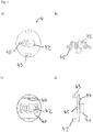
- Einhandhebelmischerkartusche consists essentially of a head piece 1, in which a spindle 2 protrudes axially, which is pivotally mounted in a rotatably mounted spindle receptacle 3 and engages in a slider 4 which is connected to a control disk 5, with a Passage disk 6 corresponds to which a bottom piece 8 connects, which receives a seal molding 7.
- the head piece 1 is sleeve-shaped and manufactured in the embodiment as a brass turned part. At its the bottom piece 8 facing end portion 10 diametrically to each other two rectangular recesses 101 are introduced into the head piece 1, are formed by the two arcuate webs 11, on the inside of a detent groove 111 is introduced. At its end opposite the webs 11, the head piece 1 has a reduced-diameter portion 15 in which diametrically opposite two radial elongated holes 152 are introduced, which serve the rotation limitation of the spindle receptacle 3. Between the elongated holes 152, two radially encircling webs 153 are formed, which have a relation to the diameter-reduced portion 15 enlarged outer diameter.
- a detent 151 in the form of an undercut forming radial locking edge is arranged in each case.
- the locking lug 151 serves to captively hold the mounting ring 16.
- a shoulder 14 is formed on the head piece 1 inside.
- a fastening ring 16 is further turned up.
- the mounting ring 16 has circumferentially outside an external thread 161 for screwing into a valve.
- the fastening ring 16 is provided with an external hexagon 163.
- a shoulder 162 is formed in the mounting ring 16 inside.
- a nose 164 is formed at its outer hexagon 163 opposite end inside the mounting ring.
- the spindle 2 is formed in the embodiment substantially cuboid. Approximately in the middle of the spindle 2, an annular coaxial Anformung 21 for receiving a - not shown - keypad formed. Above the Anformung 21 a guided to the Anformung 21 slot 25 is introduced into the spindle 2. Below the Anformung 21 is introduced through the spindle 2, a bore 22 for receiving an axle pin 23. At the end, a control head 24 designed in the form of a spherical disk is integrally formed on the spindle 2 and is flattened on its side facing the slider 4.
- the spindle receptacle 3 is formed as a substantially cylindrical plastic injection molded part.
- a two-step shoulder 31 is integrally formed on the spindle receptacle 3, the contour of which corresponds to the inner contour of the two-step shoulder 14 of the head piece 1 against which it bears.
- the above the end-side first paragraph 311 arranged opposite this diameter reduced formed second paragraph 312 of the two-stage Paragraph 31 is formed in the region of the two longitudinal side walls of the rectangular cross-section of the bushing 33 axially tapered inwardly, so that below the through hole 32, two cone-section-like bevels 313 are formed.
- the second shoulder 312 thus has a hammerhead-shaped contour in plan view.
- the sliding ring 9 has a polygonal outer contour, which is formed twelve-sided in the embodiment.
- the outer diameter of this polygonal outer contour is slightly larger than the outer diameter of the first paragraph 311, whose outer diameter is in turn dimensioned slightly smaller than the inner diameter of the shoulder 14 of the head piece. 1
- a radial through hole 32 for receiving the axle pin 23 for the spindle 2 is introduced through the spindle receptacle 3.
- the through hole 32 has a polygonal cross section, which is formed in the embodiment as a toe.
- a bushing 33 for the spindle 2 which has lateral stops 34, by which the pivot radius of the spindle 2 is limited to the axle pin 23.
- the passage 33 has a substantially rectangular cross-section.
- a slot 37 forming a gap is arranged in the spindle receptacle 3, which slot extends radially outwards and ends above a horizontal plane which is imaginary through the center axis of the through-bore 32.
- a further, fifth slot 37 extends on the longitudinal center axis of the rectangular cross section of the passage 33 from a transverse side radially outward.
- this region is surrounded by a circular arc-shaped spreading groove 38 which connects the obliquely outwardly extending four slots 37 and accommodates the two circular-arc-shaped spring elements 91, 92 arranged one above the other.
- a circular arc-shaped spreading groove 38 which connects the obliquely outwardly extending four slots 37 and accommodates the two circular-arc-shaped spring elements 91, 92 arranged one above the other.
- the lower, first spring element 91 presses the inner brake shoes 371 against the spindle 2 via its inwardly directed pretension, as a result of which a braking action with respect to a pivoting movement of the spindle 2 is effected.
- the upper, second spring element 92 presses on its outward bias the outer brake shoes 372 outwardly against the head piece 1, whereby a braking action against a rotational movement of the spindle receptacle 3 within the head piece 1 is effected.
- the Sp Opposite the located on the longitudinal central axis of the rectangular cross section of the bushing 33 fifth slot 37, the Sp Schwarznut 38 is narrowed, whereby the force acting on the middle outer brake shoe 372 biasing force of the upper second spring element 92 is increased.
- the spring elements 91, 92 have a rectangular cross-section, wherein the lower first spring element 91 is provided at an outer peripheral edge with a radius 911 and the upper second spring element 92 at an inner circumferential edge with a radius 921, whereby the introduction of the spring elements 91st , 92 is facilitated in the Sp Dahlnut 38.
- the spreading groove 38 has approximately one and a half times the width of the spring elements 91, 92, so that they are arranged offset from one another.
- the spreading groove 38 has a width that substantially corresponds to the width of the spring elements 91, 92, so that they are stacked to form a block. If the spindle is brought into the closed position, it can be supported on the spindle receptacle 3 filled with the spring elements 91, 92, wherein spring-out is avoided to the outside. The assembly of the spring elements 91, 92 is difficult in this embodiment slightly above the variant described above.
- the passage 33 terminates in a substantially parallelepiped-shaped receptacle 35 for the slider 4. Spaced to the receptacle 35 is in the spindle receptacle 3, a substantially oval indentation 36 for receiving the guide pin 44 of the slider 4 is introduced.
- the running as a plastic injection molded part slider 4 is formed substantially in the form of a circular disc on which a substantially cuboidal shaped piece 41 is formed.
- the molding 41 is formed such that it is guided in the longitudinal direction of the receptacle 35 of the spindle receptacle 3 and in the transverse direction. Axial is through the slider 4, the fitting 41 penetrating a slot 42 for receiving the control head 24 of the spindle 2 introduced. Laterally of the molding 41, a guide pin 44 is formed for engagement in the recess 36 of the spindle receptacle 3.
- two axial webs 43 for receiving the control disk 5 are integrally formed on the slider 4 on the outside.
- a dowel 45 is integrally formed on the underside for engagement in the fitting hole 53 of the control disk 5, whereby a positionally correct orientation of the control disk 5 is ensured during assembly.
- the control disk 5 is oval and made as a ceramic part. On its side facing the transmission disk 6, the control disk 5 has a centrally arranged, egg-shaped indentation 51. On its upper side opposite the indentation 51, two recesses 52 for receiving the webs 23 of the slider 4 are inserted into the control disk 5 diametrically opposite each other on the outside. Furthermore, in the control disk 5 at its the slider 4 side facing a fitting bore 53 is introduced. About the recesses 52 and the pilot hole 53, the control disk 5 is positively connected to the slider 4.
- the transmission disk 6 is also designed as a ceramic part. Through the pass-through disk 6, two inlet channels 61 for cold or hot water and a relatively enlarged outlet channel 62 for the mixed water are introduced. The inlet channels 61 and the outlet channel 62 are guided at an angle to the aperture disk 6 through them. The side offset from each other on the transmission disc 6 three recesses 63 for positive connection with the bottom piece 8 are introduced.
- the seal molding 7 is made in the embodiment of rubber. It is essentially formed by three rings 71, each on the other two rings 71 are formed so that a cloverleaf-like contour is formed. On the rings 71 of the sealing molding 7 each sealing lips 72 are integrally formed on the upper side and on the underside thereof. To stabilize the shape of the rings 71 are each provided with a support ring 73 which is disposed between the sealing lips 72 of the rings 71.
- the bottom piece 8 is substantially cylindrical. In the middle of the bottom piece 8, a cloverleaf-shaped receptacle for the sealing molding 7 is introduced. Surrounding the receptacle 81 spaced from each other three webs 82 are formed for rotationally fixed receiving the aperture plate 6. The webs 82 engage in the recesses 63 of the transmission disk 6. In order to improve the positive connection, lugs 821 are formed on two webs 82, which engage in recesses 63 of the transmission disk 6 corresponding thereto. Laterally, two shoulders 83 are formed on the bottom piece 8 diametrically opposite each other for engagement in the recesses 101 of the end-side section 10 of the head piece 1.
- two axial positioning pins 84 are further formed on the bottom piece 8.
- the positioning pins 84 are used for positioning the single lever mixer cartridge in a - not shown - fitting, which is provided for this purpose with corresponding positioning holes.
- Surrounding 8 locking lugs 85 are integrally formed on the bottom piece, which allow a latching connection between the bottom piece 8 and the head piece 1. The locking lugs 85 engage in the locking groove 111 of the arcuate webs 11 of the head piece 1 a.
- the fastening ring 16 is slipped over the reduced-diameter portion 15 of the head piece 1, wherein the locking nose 151 is forced inwardly when passing the circumferential nose 164 of the mounting ring 16.
- the latching lug 151 of the reduced-diameter portion 15 of the head piece 1 resumes its original position.
- the mounting ring 16 is thus held captive on the head piece 1. The screwing of the mounting ring 16 in a - not shown - fitting via the hexagon socket 163th
Claims (13)
- Cartouche de mitigeur monocommande comprenant une pièce têtière (1) qui reçoit une pièce de fond (8) ainsi qu'une commande à disque comprenant un disque de commande (5) agencé de façon à pouvoir tourner et/ou coulisser via une broche (2) en appui rotatif et/ou pivotant dans un logement (3) de broche, sachant que le logement de broche présente un passage (33) pour la broche (2), sachant que dans le logement (3) de broche au moins deux fentes (37) ont été ménagées dans la zone du passage (33), faisant que le contour intérieur du passage (33) est interrompu dans un segment situé à l'extrémité du logement (3) de broche, caractérisée en ce que dans le logement (3) de broche, à une certaine distance du passage (33), est agencée une gorge d'expansion (38) dans laquelle est logé au moins un corps à expansion (91, 92).
- Cartouche de mitigeur monocommande selon la revendication 1, caractérisée en ce que le logement de broche est fabriqué dans matériau autre que celui de la pièce têtière (1).
- Cartouche de mitigeur monocommande selon la revendication 1 ou 2, caractérisée en ce que la gorge d'expansion est configurée en arc.
- Cartouche de mitigeur monocommande selon l'une des revendications précédentes, caractérisée en ce que le passage (33) présente une section rectangulaire au moins à l'extrémité du logement (3) de broche ne regardant pas le disque de commande (5), sachant que le contour intérieur de la section rectangulaire du passage (33) est interrompu localement par au moins trois fentes (37).
- Cartouche de mitigeur monocommande selon la revendication 4, caractérisée en ce que le contour intérieur de la section rectangulaire du passage (33) est interrompu localement par au moins quatre fentes (37), de préférence par cinq fentes (37).
- Cartouche de mitigeur monocommande selon la revendication 4 ou 5, caractérisée en ce qu'au moins une fente (37) traversant au milieu une paroi latérale de la section rectangulaire du passage (33) aboutit dans ce dernier.
- Cartouche de mitigeur monocommande selon l'une des revendications précédentes, caractérisée en ce qu'au moins un corps à expansion est configuré en arc et présente au moins localement une largeur plus importante que la largeur de la gorge d'expansion (38).
- Cartouche de mitigeur monocommande selon l'une des revendications 1 à 6, caractérisée en ce que les corps à expansion sont formés par deux éléments ressorts (91, 92) sous précontrainte radiale orientés l'un vers l'autre.
- Cartouche de mitigeur monocommande selon la revendication 8, caractérisée en ce que que la largeur de la gorge d'expansion (38) est configurée plus importante que la largeur des éléments ressorts (91, 92).
- Cartouche de mitigeur monocommande selon la revendication 8, caractérisée en ce que la gorge d'expansion (38) présente une largeur correspondant pour l'essentiel à celle des éléments ressorts (91, 92), de sorte que ces derniers sont empilés pour former un bloc.
- Cartouche de mitigeur monocommande selon l'une des revendications précédentes, caractérisée en ce que la broche (2) est reliée avec le logement (3) de broche via un axe (23), sachant qu'au moins une fente (37) ne va pas au-delà d'un plan horizontal abstrait traversant cet axe (23).
- Cartouche de mitigeur monocommande selon l'une des revendications précédentes, caractérisée en ce que le logement (3) de broche est configuré essentiellement comme une pièce en matière plastique injectée de forme cylindrique.
- Cartouche de mitigeur monocommande selon l'une des revendications 4 à 12, caractérisée en ce qu'à au moins deux angles de la section rectangulaire du passage (33) aboutit respectivement une fente (37).
Priority Applications (3)
| Application Number | Priority Date | Filing Date | Title |
|---|---|---|---|
| EP15157872.1A EP3064812B1 (fr) | 2015-03-05 | 2015-03-05 | Cartouche de mitigeur |
| ES15157872.1T ES2621567T3 (es) | 2015-03-05 | 2015-03-05 | Cartucho de palanca monomando |
| HUE15157872A HUE031718T2 (en) | 2015-03-05 | 2015-03-05 | Single lever lift |
Applications Claiming Priority (1)
| Application Number | Priority Date | Filing Date | Title |
|---|---|---|---|
| EP15157872.1A EP3064812B1 (fr) | 2015-03-05 | 2015-03-05 | Cartouche de mitigeur |
Publications (2)
| Publication Number | Publication Date |
|---|---|
| EP3064812A1 EP3064812A1 (fr) | 2016-09-07 |
| EP3064812B1 true EP3064812B1 (fr) | 2017-01-25 |
Family
ID=52629423
Family Applications (1)
| Application Number | Title | Priority Date | Filing Date |
|---|---|---|---|
| EP15157872.1A Active EP3064812B1 (fr) | 2015-03-05 | 2015-03-05 | Cartouche de mitigeur |
Country Status (3)
| Country | Link |
|---|---|
| EP (1) | EP3064812B1 (fr) |
| ES (1) | ES2621567T3 (fr) |
| HU (1) | HUE031718T2 (fr) |
Family Cites Families (1)
| Publication number | Priority date | Publication date | Assignee | Title |
|---|---|---|---|---|
| DE202013104200U1 (de) | 2013-09-13 | 2013-10-10 | Flühs Drehtechnik GmbH | Einhandhebelkartusche |
-
2015
- 2015-03-05 ES ES15157872.1T patent/ES2621567T3/es active Active
- 2015-03-05 EP EP15157872.1A patent/EP3064812B1/fr active Active
- 2015-03-05 HU HUE15157872A patent/HUE031718T2/en unknown
Non-Patent Citations (1)
| Title |
|---|
| None * |
Also Published As
| Publication number | Publication date |
|---|---|
| HUE031718T2 (en) | 2017-07-28 |
| EP3064812A1 (fr) | 2016-09-07 |
| ES2621567T3 (es) | 2017-07-04 |
Similar Documents
| Publication | Publication Date | Title |
|---|---|---|
| DE3419209C2 (de) | Mischventil | |
| EP2634464B1 (fr) | Cartouche de mélangeur à levier à une main | |
| DE4038141C1 (fr) | ||
| EP2806197B9 (fr) | Robinet à mono-commande, en particulier mitigeur à mono-commande | |
| DE4344773A1 (de) | Thermostataufsatz für Heizkörperventile | |
| DE102012110079A1 (de) | Positioniermechanismus für ein handwerkzeug | |
| EP2634463B1 (fr) | Cartouche de mélangeur à levier à une main | |
| EP2771600B1 (fr) | Cartouche pour mélangeur monocommande | |
| DE102013100772A9 (de) | Steckverbindung für Fluid-Leitungen und Halteteil für eine derartige Steckverbindung | |
| DE102014102662A1 (de) | Steckverbindung für Fluid-Leitungen und Halteteil für eine derartige Steckverbindung | |
| EP2962020B1 (fr) | Cartouche de mitigeur | |
| DE2702290A1 (de) | Stroemungsmittelkupplung | |
| EP3064812B1 (fr) | Cartouche de mitigeur | |
| EP0754827A2 (fr) | Dispositif pour la fixation amovible et axialement non coulissante d'une poignée sur un élément de palier, notamment pour une poignée de porte ou fenêtre | |
| EP3591267B1 (fr) | Partie supérieure de soupape | |
| DE102010000910B3 (de) | Ventilkartusche für eine Sanitärarmatur | |
| DE202013104200U1 (de) | Einhandhebelkartusche | |
| DE2900601A1 (de) | Absperrorgan | |
| DE202015101083U1 (de) | Einhandhebelkartusche | |
| EP2962021B1 (fr) | Cartouche de mitigeur | |
| EP3062003B1 (fr) | Cartouche de mitigeur | |
| WO2020007565A1 (fr) | Partie supérieure de soupape | |
| EP3265704B1 (fr) | Pièce supérieure de soupape pour robinetterie | |
| DE102019123485A1 (de) | Öffnungs- und Schliessventil | |
| WO2013010845A1 (fr) | Partie supérieure de soupape pour robinetterie |
Legal Events
| Date | Code | Title | Description |
|---|---|---|---|
| PUAI | Public reference made under article 153(3) epc to a published international application that has entered the european phase |
Free format text: ORIGINAL CODE: 0009012 |
|
| 17P | Request for examination filed |
Effective date: 20151021 |
|
| AK | Designated contracting states |
Kind code of ref document: A1 Designated state(s): AL AT BE BG CH CY CZ DE DK EE ES FI FR GB GR HR HU IE IS IT LI LT LU LV MC MK MT NL NO PL PT RO RS SE SI SK SM TR |
|
| AX | Request for extension of the european patent |
Extension state: BA ME |
|
| GRAP | Despatch of communication of intention to grant a patent |
Free format text: ORIGINAL CODE: EPIDOSNIGR1 |
|
| RIC1 | Information provided on ipc code assigned before grant |
Ipc: F16K 27/04 20060101ALI20160915BHEP Ipc: F16K 11/078 20060101AFI20160915BHEP |
|
| INTG | Intention to grant announced |
Effective date: 20161007 |
|
| GRAS | Grant fee paid |
Free format text: ORIGINAL CODE: EPIDOSNIGR3 |
|
| GRAA | (expected) grant |
Free format text: ORIGINAL CODE: 0009210 |
|
| AK | Designated contracting states |
Kind code of ref document: B1 Designated state(s): AL AT BE BG CH CY CZ DE DK EE ES FI FR GB GR HR HU IE IS IT LI LT LU LV MC MK MT NL NO PL PT RO RS SE SI SK SM TR |
|
| REG | Reference to a national code |
Ref country code: GB Ref legal event code: FG4D Free format text: NOT ENGLISH |
|
| REG | Reference to a national code |
Ref country code: CH Ref legal event code: EP |
|
| REG | Reference to a national code |
Ref country code: AT Ref legal event code: REF Ref document number: 864353 Country of ref document: AT Kind code of ref document: T Effective date: 20170215 |
|
| REG | Reference to a national code |
Ref country code: IE Ref legal event code: FG4D Free format text: LANGUAGE OF EP DOCUMENT: GERMAN |
|
| REG | Reference to a national code |
Ref country code: DE Ref legal event code: R096 Ref document number: 502015000509 Country of ref document: DE |
|
| REG | Reference to a national code |
Ref country code: LT Ref legal event code: MG4D |
|
| REG | Reference to a national code |
Ref country code: NL Ref legal event code: MP Effective date: 20170125 |
|
| PG25 | Lapsed in a contracting state [announced via postgrant information from national office to epo] |
Ref country code: NL Free format text: LAPSE BECAUSE OF FAILURE TO SUBMIT A TRANSLATION OF THE DESCRIPTION OR TO PAY THE FEE WITHIN THE PRESCRIBED TIME-LIMIT Effective date: 20170125 |
|
| REG | Reference to a national code |
Ref country code: ES Ref legal event code: FG2A Ref document number: 2621567 Country of ref document: ES Kind code of ref document: T3 Effective date: 20170704 |
|
| REG | Reference to a national code |
Ref country code: HU Ref legal event code: AG4A Ref document number: E031718 Country of ref document: HU |
|
| PG25 | Lapsed in a contracting state [announced via postgrant information from national office to epo] |
Ref country code: FI Free format text: LAPSE BECAUSE OF FAILURE TO SUBMIT A TRANSLATION OF THE DESCRIPTION OR TO PAY THE FEE WITHIN THE PRESCRIBED TIME-LIMIT Effective date: 20170125 Ref country code: GR Free format text: LAPSE BECAUSE OF FAILURE TO SUBMIT A TRANSLATION OF THE DESCRIPTION OR TO PAY THE FEE WITHIN THE PRESCRIBED TIME-LIMIT Effective date: 20170426 Ref country code: HR Free format text: LAPSE BECAUSE OF FAILURE TO SUBMIT A TRANSLATION OF THE DESCRIPTION OR TO PAY THE FEE WITHIN THE PRESCRIBED TIME-LIMIT Effective date: 20170125 Ref country code: LT Free format text: LAPSE BECAUSE OF FAILURE TO SUBMIT A TRANSLATION OF THE DESCRIPTION OR TO PAY THE FEE WITHIN THE PRESCRIBED TIME-LIMIT Effective date: 20170125 Ref country code: IS Free format text: LAPSE BECAUSE OF FAILURE TO SUBMIT A TRANSLATION OF THE DESCRIPTION OR TO PAY THE FEE WITHIN THE PRESCRIBED TIME-LIMIT Effective date: 20170525 Ref country code: NO Free format text: LAPSE BECAUSE OF FAILURE TO SUBMIT A TRANSLATION OF THE DESCRIPTION OR TO PAY THE FEE WITHIN THE PRESCRIBED TIME-LIMIT Effective date: 20170425 |
|
| PG25 | Lapsed in a contracting state [announced via postgrant information from national office to epo] |
Ref country code: PL Free format text: LAPSE BECAUSE OF FAILURE TO SUBMIT A TRANSLATION OF THE DESCRIPTION OR TO PAY THE FEE WITHIN THE PRESCRIBED TIME-LIMIT Effective date: 20170125 Ref country code: BG Free format text: LAPSE BECAUSE OF FAILURE TO SUBMIT A TRANSLATION OF THE DESCRIPTION OR TO PAY THE FEE WITHIN THE PRESCRIBED TIME-LIMIT Effective date: 20170425 Ref country code: PT Free format text: LAPSE BECAUSE OF FAILURE TO SUBMIT A TRANSLATION OF THE DESCRIPTION OR TO PAY THE FEE WITHIN THE PRESCRIBED TIME-LIMIT Effective date: 20170525 Ref country code: LV Free format text: LAPSE BECAUSE OF FAILURE TO SUBMIT A TRANSLATION OF THE DESCRIPTION OR TO PAY THE FEE WITHIN THE PRESCRIBED TIME-LIMIT Effective date: 20170125 Ref country code: SE Free format text: LAPSE BECAUSE OF FAILURE TO SUBMIT A TRANSLATION OF THE DESCRIPTION OR TO PAY THE FEE WITHIN THE PRESCRIBED TIME-LIMIT Effective date: 20170125 Ref country code: RS Free format text: LAPSE BECAUSE OF FAILURE TO SUBMIT A TRANSLATION OF THE DESCRIPTION OR TO PAY THE FEE WITHIN THE PRESCRIBED TIME-LIMIT Effective date: 20170125 |
|
| REG | Reference to a national code |
Ref country code: DE Ref legal event code: R097 Ref document number: 502015000509 Country of ref document: DE |
|
| PG25 | Lapsed in a contracting state [announced via postgrant information from national office to epo] |
Ref country code: RO Free format text: LAPSE BECAUSE OF FAILURE TO SUBMIT A TRANSLATION OF THE DESCRIPTION OR TO PAY THE FEE WITHIN THE PRESCRIBED TIME-LIMIT Effective date: 20170125 Ref country code: EE Free format text: LAPSE BECAUSE OF FAILURE TO SUBMIT A TRANSLATION OF THE DESCRIPTION OR TO PAY THE FEE WITHIN THE PRESCRIBED TIME-LIMIT Effective date: 20170125 Ref country code: SK Free format text: LAPSE BECAUSE OF FAILURE TO SUBMIT A TRANSLATION OF THE DESCRIPTION OR TO PAY THE FEE WITHIN THE PRESCRIBED TIME-LIMIT Effective date: 20170125 Ref country code: CZ Free format text: LAPSE BECAUSE OF FAILURE TO SUBMIT A TRANSLATION OF THE DESCRIPTION OR TO PAY THE FEE WITHIN THE PRESCRIBED TIME-LIMIT Effective date: 20170125 |
|
| PG25 | Lapsed in a contracting state [announced via postgrant information from national office to epo] |
Ref country code: MC Free format text: LAPSE BECAUSE OF FAILURE TO SUBMIT A TRANSLATION OF THE DESCRIPTION OR TO PAY THE FEE WITHIN THE PRESCRIBED TIME-LIMIT Effective date: 20170125 Ref country code: SM Free format text: LAPSE BECAUSE OF FAILURE TO SUBMIT A TRANSLATION OF THE DESCRIPTION OR TO PAY THE FEE WITHIN THE PRESCRIBED TIME-LIMIT Effective date: 20170125 Ref country code: DK Free format text: LAPSE BECAUSE OF FAILURE TO SUBMIT A TRANSLATION OF THE DESCRIPTION OR TO PAY THE FEE WITHIN THE PRESCRIBED TIME-LIMIT Effective date: 20170125 |
|
| PLBE | No opposition filed within time limit |
Free format text: ORIGINAL CODE: 0009261 |
|
| STAA | Information on the status of an ep patent application or granted ep patent |
Free format text: STATUS: NO OPPOSITION FILED WITHIN TIME LIMIT |
|
| REG | Reference to a national code |
Ref country code: IE Ref legal event code: MM4A |
|
| REG | Reference to a national code |
Ref country code: FR Ref legal event code: ST Effective date: 20171130 |
|
| 26N | No opposition filed |
Effective date: 20171026 |
|
| PG25 | Lapsed in a contracting state [announced via postgrant information from national office to epo] |
Ref country code: LU Free format text: LAPSE BECAUSE OF NON-PAYMENT OF DUE FEES Effective date: 20170305 Ref country code: FR Free format text: LAPSE BECAUSE OF NON-PAYMENT OF DUE FEES Effective date: 20170331 |
|
| PG25 | Lapsed in a contracting state [announced via postgrant information from national office to epo] |
Ref country code: IE Free format text: LAPSE BECAUSE OF NON-PAYMENT OF DUE FEES Effective date: 20170305 Ref country code: SI Free format text: LAPSE BECAUSE OF FAILURE TO SUBMIT A TRANSLATION OF THE DESCRIPTION OR TO PAY THE FEE WITHIN THE PRESCRIBED TIME-LIMIT Effective date: 20170125 |
|
| REG | Reference to a national code |
Ref country code: BE Ref legal event code: MM Effective date: 20170331 |
|
| PG25 | Lapsed in a contracting state [announced via postgrant information from national office to epo] |
Ref country code: BE Free format text: LAPSE BECAUSE OF NON-PAYMENT OF DUE FEES Effective date: 20170331 |
|
| PG25 | Lapsed in a contracting state [announced via postgrant information from national office to epo] |
Ref country code: MT Free format text: LAPSE BECAUSE OF FAILURE TO SUBMIT A TRANSLATION OF THE DESCRIPTION OR TO PAY THE FEE WITHIN THE PRESCRIBED TIME-LIMIT Effective date: 20170125 |
|
| REG | Reference to a national code |
Ref country code: CH Ref legal event code: PL |
|
| PG25 | Lapsed in a contracting state [announced via postgrant information from national office to epo] |
Ref country code: CH Free format text: LAPSE BECAUSE OF NON-PAYMENT OF DUE FEES Effective date: 20180331 Ref country code: LI Free format text: LAPSE BECAUSE OF NON-PAYMENT OF DUE FEES Effective date: 20180331 |
|
| PG25 | Lapsed in a contracting state [announced via postgrant information from national office to epo] |
Ref country code: CY Free format text: LAPSE BECAUSE OF FAILURE TO SUBMIT A TRANSLATION OF THE DESCRIPTION OR TO PAY THE FEE WITHIN THE PRESCRIBED TIME-LIMIT Effective date: 20170125 |
|
| GBPC | Gb: european patent ceased through non-payment of renewal fee |
Effective date: 20190305 |
|
| PG25 | Lapsed in a contracting state [announced via postgrant information from national office to epo] |
Ref country code: MK Free format text: LAPSE BECAUSE OF FAILURE TO SUBMIT A TRANSLATION OF THE DESCRIPTION OR TO PAY THE FEE WITHIN THE PRESCRIBED TIME-LIMIT Effective date: 20170125 |
|
| PG25 | Lapsed in a contracting state [announced via postgrant information from national office to epo] |
Ref country code: GB Free format text: LAPSE BECAUSE OF NON-PAYMENT OF DUE FEES Effective date: 20190305 |
|
| PG25 | Lapsed in a contracting state [announced via postgrant information from national office to epo] |
Ref country code: AL Free format text: LAPSE BECAUSE OF FAILURE TO SUBMIT A TRANSLATION OF THE DESCRIPTION OR TO PAY THE FEE WITHIN THE PRESCRIBED TIME-LIMIT Effective date: 20170125 |
|
| REG | Reference to a national code |
Ref country code: AT Ref legal event code: MM01 Ref document number: 864353 Country of ref document: AT Kind code of ref document: T Effective date: 20200305 |
|
| PG25 | Lapsed in a contracting state [announced via postgrant information from national office to epo] |
Ref country code: AT Free format text: LAPSE BECAUSE OF NON-PAYMENT OF DUE FEES Effective date: 20200305 |
|
| PGFP | Annual fee paid to national office [announced via postgrant information from national office to epo] |
Ref country code: TR Payment date: 20230302 Year of fee payment: 9 Ref country code: HU Payment date: 20230226 Year of fee payment: 9 Ref country code: DE Payment date: 20230223 Year of fee payment: 9 |
|
| P01 | Opt-out of the competence of the unified patent court (upc) registered |
Effective date: 20230528 |
|
| PGFP | Annual fee paid to national office [announced via postgrant information from national office to epo] |
Ref country code: IT Payment date: 20230331 Year of fee payment: 9 Ref country code: ES Payment date: 20230414 Year of fee payment: 9 |