EP2962003B1 - Vorrichtung zum lösbaren anbinden eines betätigungsgliedes an einen geber oder nehmer - Google Patents
Vorrichtung zum lösbaren anbinden eines betätigungsgliedes an einen geber oder nehmer Download PDFInfo
- Publication number
- EP2962003B1 EP2962003B1 EP14786660.2A EP14786660A EP2962003B1 EP 2962003 B1 EP2962003 B1 EP 2962003B1 EP 14786660 A EP14786660 A EP 14786660A EP 2962003 B1 EP2962003 B1 EP 2962003B1
- Authority
- EP
- European Patent Office
- Prior art keywords
- sleeve
- embodied
- actuating member
- reception element
- bushing
- Prior art date
- Legal status (The legal status is an assumption and is not a legal conclusion. Google has not performed a legal analysis and makes no representation as to the accuracy of the status listed.)
- Active
Links
- 238000013016 damping Methods 0.000 claims description 45
- 238000007373 indentation Methods 0.000 claims 1
- 230000000737 periodic effect Effects 0.000 claims 1
- 230000005540 biological transmission Effects 0.000 description 13
- 238000004519 manufacturing process Methods 0.000 description 4
- 239000004033 plastic Substances 0.000 description 4
- 229920003023 plastic Polymers 0.000 description 4
- 229920001971 elastomer Polymers 0.000 description 2
- 238000005538 encapsulation Methods 0.000 description 2
- 230000001747 exhibiting effect Effects 0.000 description 2
- 229920001343 polytetrafluoroethylene Polymers 0.000 description 2
- 239000004810 polytetrafluoroethylene Substances 0.000 description 2
- 230000001629 suppression Effects 0.000 description 2
- 241000309551 Arthraxon hispidus Species 0.000 description 1
- 239000004952 Polyamide Substances 0.000 description 1
- 238000010276 construction Methods 0.000 description 1
- 230000001419 dependent effect Effects 0.000 description 1
- 230000000694 effects Effects 0.000 description 1
- 239000000806 elastomer Substances 0.000 description 1
- 238000002474 experimental method Methods 0.000 description 1
- 238000002347 injection Methods 0.000 description 1
- 239000007924 injection Substances 0.000 description 1
- 238000003780 insertion Methods 0.000 description 1
- 230000037431 insertion Effects 0.000 description 1
- 239000000463 material Substances 0.000 description 1
- 238000000465 moulding Methods 0.000 description 1
- 230000002093 peripheral effect Effects 0.000 description 1
- 229920002647 polyamide Polymers 0.000 description 1
- -1 polytetrafluoroethylene Polymers 0.000 description 1
- 229920003051 synthetic elastomer Polymers 0.000 description 1
Images


Classifications
-
- F—MECHANICAL ENGINEERING; LIGHTING; HEATING; WEAPONS; BLASTING
- F16—ENGINEERING ELEMENTS AND UNITS; GENERAL MEASURES FOR PRODUCING AND MAINTAINING EFFECTIVE FUNCTIONING OF MACHINES OR INSTALLATIONS; THERMAL INSULATION IN GENERAL
- F16C—SHAFTS; FLEXIBLE SHAFTS; ELEMENTS OR CRANKSHAFT MECHANISMS; ROTARY BODIES OTHER THAN GEARING ELEMENTS; BEARINGS
- F16C11/00—Pivots; Pivotal connections
- F16C11/04—Pivotal connections
- F16C11/06—Ball-joints; Other joints having more than one degree of angular freedom, i.e. universal joints
- F16C11/08—Ball-joints; Other joints having more than one degree of angular freedom, i.e. universal joints with resilient bearings
- F16C11/083—Ball-joints; Other joints having more than one degree of angular freedom, i.e. universal joints with resilient bearings by means of parts of rubber or like materials
-
- F—MECHANICAL ENGINEERING; LIGHTING; HEATING; WEAPONS; BLASTING
- F16—ENGINEERING ELEMENTS AND UNITS; GENERAL MEASURES FOR PRODUCING AND MAINTAINING EFFECTIVE FUNCTIONING OF MACHINES OR INSTALLATIONS; THERMAL INSULATION IN GENERAL
- F16C—SHAFTS; FLEXIBLE SHAFTS; ELEMENTS OR CRANKSHAFT MECHANISMS; ROTARY BODIES OTHER THAN GEARING ELEMENTS; BEARINGS
- F16C11/00—Pivots; Pivotal connections
- F16C11/04—Pivotal connections
- F16C11/06—Ball-joints; Other joints having more than one degree of angular freedom, i.e. universal joints
- F16C11/0695—Mounting of ball-joints, e.g. fixing them to a connecting rod
-
- F—MECHANICAL ENGINEERING; LIGHTING; HEATING; WEAPONS; BLASTING
- F16—ENGINEERING ELEMENTS AND UNITS; GENERAL MEASURES FOR PRODUCING AND MAINTAINING EFFECTIVE FUNCTIONING OF MACHINES OR INSTALLATIONS; THERMAL INSULATION IN GENERAL
- F16C—SHAFTS; FLEXIBLE SHAFTS; ELEMENTS OR CRANKSHAFT MECHANISMS; ROTARY BODIES OTHER THAN GEARING ELEMENTS; BEARINGS
- F16C7/00—Connecting-rods or like links pivoted at both ends; Construction of connecting-rod heads
- F16C7/02—Constructions of connecting-rods with constant length
-
- F—MECHANICAL ENGINEERING; LIGHTING; HEATING; WEAPONS; BLASTING
- F16—ENGINEERING ELEMENTS AND UNITS; GENERAL MEASURES FOR PRODUCING AND MAINTAINING EFFECTIVE FUNCTIONING OF MACHINES OR INSTALLATIONS; THERMAL INSULATION IN GENERAL
- F16F—SPRINGS; SHOCK-ABSORBERS; MEANS FOR DAMPING VIBRATION
- F16F1/00—Springs
- F16F1/36—Springs made of rubber or other material having high internal friction, e.g. thermoplastic elastomers
- F16F1/373—Springs made of rubber or other material having high internal friction, e.g. thermoplastic elastomers characterised by having a particular shape
- F16F1/376—Springs made of rubber or other material having high internal friction, e.g. thermoplastic elastomers characterised by having a particular shape having projections, studs, serrations or the like on at least one surface
-
- F—MECHANICAL ENGINEERING; LIGHTING; HEATING; WEAPONS; BLASTING
- F16—ENGINEERING ELEMENTS AND UNITS; GENERAL MEASURES FOR PRODUCING AND MAINTAINING EFFECTIVE FUNCTIONING OF MACHINES OR INSTALLATIONS; THERMAL INSULATION IN GENERAL
- F16H—GEARING
- F16H61/00—Control functions within control units of change-speed- or reversing-gearings for conveying rotary motion ; Control of exclusively fluid gearing, friction gearing, gearings with endless flexible members or other particular types of gearing
- F16H61/26—Generation or transmission of movements for final actuating mechanisms
Definitions
- the present invention relates to a device for releasably connecting an actuator to a donor or taker, for example to a shift lever or a transmission of a motor vehicle, with a connection point for fixing the actuator and a receptacle for fixing a connection element of the transmitter or receiver, wherein the receptacle a essentially having an eyelet-like outer receiving element and an inner receiving element arranged therein, between which an elastic damping element is arranged.
- the invention further relates to an actuator with such a tether.
- Tying devices of the type mentioned are, for example US 5,265,495 A1 and EP 2 278 178 B1 known and are used, inter alia, in the automotive sector, an actuator, such as a control cable or an actuating rod, with its help as in a manual transmission, the predetermined by the driver by actuating the shift lever switching movement is transmitted to the selector lever on the gear housing, each end to the shift lever and the Connect gear selector lever.
- an actuator such as a control cable or an actuating rod
- the actuating member is connected to a connection point of the connection device, which in turn has a receptacle which is fixed to a connection element of the take or donor, for example an actuation pin of the gear selector lever or a connection element of the shift lever.
- the elastic damping element in the receptacle which is arranged between the eyelet-like outer receiving element and the inner receiving element received therein, serves to prevent the Transmission of vibrations of the transmission from the gear selector lever on the actuator and subsequently dampen the actuator to the shift lever, so that as a result undesirable vibrations on the shift lever or in the interior of the vehicle as possible avoided.
- connection devices of the type mentioned are also from the DE 197 55 284 A1 such as EP 1 798 431 A1 known.
- the DE 197 55 284 A1 discloses a ball joint with a pin arranged on a ball joint, which is partially surrounded by a bearing shell, wherein the dome-shaped inner surface having bearing shell is inserted by means of a substantially cylindrical outer circumferential surface in a receiving bore of a housing.
- the bearing shell is embedded on its outer circumferential surface in a sleeve made of a rubber-elastic elastomer, which rests in the receiving bore.
- the connection of the actuator is such that a lever extends from the housing, which is provided on the lateral surface with an external thread, wherein a non-illustrated shift lever of the motor vehicle can be fixed to this external thread.
- An attachment device with a receptacle with an outer receiving element and an inner receiving element disposed therein, between which an elastic damping element is arranged also discloses the EP 1 798 431 A1 ,
- the damping element is cylindrical.
- the connection for fixing a moving member takes place by encapsulation.
- From the DE 197 31 039 A1 is a device for connecting a Bowden cable to the change gear of a motor vehicle, the device consists of a Bowden cable, the tail is connected to a fixed in the device receiving sleeve and the device further comprises a damping element, with a arranged therein Plastic core, the opening of which receives a transmission connection element. Also in this connection device known from the prior art, the connection of a connection member to the encoder or slave takes place by encapsulation.
- Object of the present invention is therefore to improve a tether and an actuator with a connection device of the type mentioned in that the transmission of unwanted vibrations from the transmission via the actuator in the interior of the vehicle is reduced to a minimum.
- connection of the actuator to the tethering device should be technically simplified.
- the device for releasably connecting an actuator to a donor or taker according to the preamble of claim 1 is characterized in that the damping element is designed as a separate component and on its outer or inner receiving element facing wall a periodically and / or alternately formed wave profile and the Connection point has a threaded insert for fixing the actuator.
- a damping element which is arranged between the inner and the outer receiving element of the tether and a wave profile-like outer wall, that is a Wavy profile, the outer receiving element out, has significantly improved damping properties, which relates to the unwanted transmission of vibrations to the transmission member.
- the reason for this is, inter alia, that the contact surface of the damping element to the outer receiving element is minimized by the profile, in particular wave profile out so that the transmission of disturbing vibrations is suppressed in an advantageous manner.
- the tether has a threaded insert on which advantageously the actuator can be fixed by means of a screw.
- a threaded insert allows a cost-effective, flexible and in particular again releasable connection of the actuator to the tether.
- the profile is periodically formed on the outer wall of the damping element and / or formed of alternating part-circular, in particular semicircular extensions and depressions.
- At least one of the edges or edges of the damping element is in a further advantageous embodiment of the invention, in particular bevelled or rounded.
- the damping element is designed as a cylindrical, annular component.
- a particularly cost-effective and stable tying device is achieved in that the outer receiving element and the connection point are integrally formed, in particular as a common base body.
- the outer receiving element, the inner receiving element and / or the damping element is substantially annular and / or hollow cylindrical are. In this way, in particular a rotational movement of the tethering device or of the actuating element relative to the connecting element of the transmitter or receiver is made possible around the longitudinal or rotational axis of the eye-like outer receiving element.
- connection device has a socket in which the connection element of the encoder or receiver, in particular by means of a latching and / or Knipstagen, is determinable.
- the socket is formed as a socket of a ball joint in which a ball head exhibiting a connecting element of Encoder or receiver can be fixed, in particular latched or clipped.
- the inner receiving element has a preferably cylindrical sleeve in which the socket is arranged.
- a two-part construction of sleeve and socket accommodated therein allows the inner receiving element to be adapted, on the one hand, to the shape of the connecting element by means of the bush and, on the other hand, via the sleeve to the shape of the outer receiving element.
- the connection device as a whole can be flexibly adapted to different encoders or receivers.
- the sleeve has a passage taper, by means of which the preferably correspondingly tapered bushing is engaged by molding flow.
- the inner receiving element in the axial direction relative to the eyelet-shaped outer receiving element each end has a closing element, by means of which the inner receiving element, in particular the sleeve and / or the sleeve, in the axial direction on the outer receiving element is fixed.
- the socket and at least one of the two end elements in one piece, in particular as a hollow cylinder with a one-round circumferential collar or flange formed.
- the respective end-side termination elements are formed such that they have greater radial extent than the sleeve or the socket, so that by means of shape flow axial fixing of the inner receiving element via the front side or on a flat side on the outer receiving element fitting end element is achieved. It is conceivable, for example, that at least one of the two end elements is formed lid or plate or disc-like.
- the hole-disc-like design is particularly suitable for that side of the inner or outer Receiving element, via which the connection element, in particular the ball joint head, is inserted into the socket.
- At least one of the two end elements has a frontally circumferential groove into which the sleeve engages in the assembled position. It is conceivable, for example, that the sleeve is pressed into the circumferential groove, glued or clipped.
- the threaded insert is designed as a nut, in particular as a polygonal nut.
- a polygonal nut in particular standard components can be used, which has an advantageous effect on the manufacturing cost of the connection device.
- the application point a support and / or a guide for the actuator to be connected, in particular for a Connecting lug to be connected to an actuator.
- An independent idea of the invention relates to an actuating member having at least one connecting device, of the kind previously described, arranged at one end, preferably in the region of a connecting lug.
- the axis of the threaded insert or the nut is orthogonal to the axis of the receptacle.
- the actuator it is provided that at least one end, preferably in the region of a terminal lug, a hole, in particular a slot, is provided, through which a screw in the threaded insert can be screwed for fixing the actuator to the device.
- a further advantageous embodiment of the invention provides that the damping element is designed as a separately manageable component.
- the Fig. 1 and 2 show a possible embodiment of a device 1 according to the invention for releasably connecting an actuating member to a donor or taker, for example to a shift lever or a transmission of a motor vehicle.
- the device 1 a connection point 10 for fixing the actuator and a receptacle 20 for fixing a connection element of the encoder or receiver, wherein the receptacle 20 consists of a substantially eyelet-like outer receiving element 30 and an inner receiving element 40 disposed therein.
- the outer receiving element 30 and the connection point 10 integrally formed to form a common base body, wherein the main body has a substantially elongated shape, at one end of the eye-like, approximately annular outer receiving element 30 and at the other end the connection point 10 for Setting the actuator are arranged.
- an elastic damping element 50 is arranged according to the invention, which has a circumferential wave profile 52 on its outer wall facing the outer receiving element 30 51.
- Fig. 1 and 2 consists of the inner receiving element 40 a total of four components, namely a cover-like closure member 43, a disc-like end member 44, a sleeve 41 and a receptacle 42 received therein.
- the sleeve 42 is formed as a socket of a ball joint, in which a ball head exhibiting a connection element of the encoder or receiver can be fixed.
- the joint socket in particular latching or Klipsharmsstoff, by means of which the connection element in a particularly simple manner and in particular again releasably in the inner receiving element 40, ie in the socket 42, can be fixed.
- the sleeve 42 is received in the present embodiment in a cylindrical sleeve 41 which has a passage taper 46, by means of which the corresponding tapered bushing 42 is fixed in the mounting position in an axial direction within the sleeve 41.
- the bushing 42 is fixed in the sleeve 41 by the plate-like closing element 43, the front side has a circumferential groove 45, in which the sleeve 41 engages in the assembled position.
- the closing element 43 has a greater extent in the radial direction than the sleeve 41 and comes with the overlapping area in contact position with the outer receiving element 30, whereby the inner receiving member 40 relative to the outer receiving member 30 is fixed in an axial direction by means of positive locking.
- a further closing element 44 is provided, which is formed in one piece with the sleeve 41 in the present embodiment.
- Sleeve 41 and end member 44 together form a hollow cylinder having a circumferential collar or flange which is formed by the disc-like end member 44.
- the attachment point 10 a support 13 and thereof laterally lifting guides 14, in which the to be connected and not shown actuator, in particular a connecting lug of an actuator to be connected, is added.
- the connection point 10 has a threaded insert 11.
- the threaded insert 11 is a polygonal punch nut 12, which is shown in cross-section substantially trapezoidal.
- the nut 12 is integrated by overmolding in the present case of plastic base body 60. It is also conceivable that the threaded member 11 is inserted into a corresponding opening in the base body 60, clipped, snapped or glued.
- the polygonal outer contour of the threaded element causes in an advantageous manner a rotation.
- the actuator in particular in the region of the terminal lug, has a slot, whereby a continuous adjustment and pre-fixing the tether 1 on the actuator is possible.
- Fig. 3 shows the elastic damping element 50 according to the invention, which has a peripheral wave profile 52 at its outer walls 51 facing the outer receiving element 30.
- the wave profile is formed periodically, in particular from alternating semicircular extensions 53 and depressions 54.
- the frontal boundaries 55, 56 of the damping element 50 are drawn, bent in the present embodiment. This will be an introduction of the Damping element 50 between the outer eyelet-like receiving element 30 and the inner receiving element 40 arranged therein facilitates.
- extensions or profiled end sections can be provided according to an independent aspect of the invention on the end faces of the damping element.
- a circumferential, annular extension is arranged on at least one end face of the damping element. It has been found to be advantageous if the diameter of the annular extension is greater than the wall thickness of the cylindrical portion of the damping element (50).
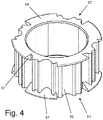
- Fig. 4 shows a further embodiment of the damping element, which is provided with the reference numeral 50.
- projections 57 are arranged, which protrude beyond the outer wall of the damping element 50 and tapering from the outer wall 51 to the end face 58 towards.
- the extensions 57 is a damping in the direction of - in FIG. 4 not shown - vehicle Z-axis reached.
- the extensions 57 are arranged offset at the opposite end faces 58, thereby the damping element can be produced inexpensively, since a simple demolding during production by means of a tool is possible.
- Another embodiment for damping in the direction of - in FIG. 4 not shown - vehicle Z-axis is to be attached to the encircling collar of in FIG. 4 not shown sleeve 41 or on the damping element facing side of in FIG. 4 Not shown end member 43 to arrange a soft component.
- the soft component is injection-molded in an injection mold onto the intended surfaces of the sleeve 41 or the closing element 43.
- the soft component may be formed as a knob or wedge or web, which are arranged circumferentially on the collar of the sleeve 41 or on the damping element 50 facing side of the closing element 43.
- the number of nubs or wedges or webs can vary.
- the base body 60 and the sleeve 42, the sleeve 41 and the end elements 43, 44 are preferably made of plastic, for example made of polyamide, which are optionally glass-reinforced and / or polytetrafluoroethylene (PTFE) component.
- plastics for example made of polyamide, which are optionally glass-reinforced and / or polytetrafluoroethylene (PTFE) component.
- PTFE polytetrafluoroethylene
Landscapes
- Engineering & Computer Science (AREA)
- General Engineering & Computer Science (AREA)
- Mechanical Engineering (AREA)
- Vibration Prevention Devices (AREA)
- Arrangement Or Mounting Of Control Devices For Change-Speed Gearing (AREA)
- Mechanical Control Devices (AREA)
Applications Claiming Priority (2)
| Application Number | Priority Date | Filing Date | Title |
|---|---|---|---|
| DE202013104768U DE202013104768U1 (de) | 2013-10-23 | 2013-10-23 | Vorrichtung zum lösbaren Anbinden eines Betätigungsgliedes an einen Geber oder Nehmer |
| PCT/EP2014/072345 WO2015059056A1 (de) | 2013-10-23 | 2014-10-17 | Vorrichtung zum lösbaren anbinden eines betätigungsgliedes an einen geber oder nehmer |
Publications (2)
| Publication Number | Publication Date |
|---|---|
| EP2962003A1 EP2962003A1 (de) | 2016-01-06 |
| EP2962003B1 true EP2962003B1 (de) | 2018-03-14 |
Family
ID=49781044
Family Applications (1)
| Application Number | Title | Priority Date | Filing Date |
|---|---|---|---|
| EP14786660.2A Active EP2962003B1 (de) | 2013-10-23 | 2014-10-17 | Vorrichtung zum lösbaren anbinden eines betätigungsgliedes an einen geber oder nehmer |
Country Status (8)
| Country | Link |
|---|---|
| US (2) | US20160245332A1 (ko) |
| EP (1) | EP2962003B1 (ko) |
| JP (1) | JP6397905B2 (ko) |
| KR (1) | KR102102503B1 (ko) |
| CN (1) | CN105683595B (ko) |
| DE (1) | DE202013104768U1 (ko) |
| ES (1) | ES2672742T3 (ko) |
| WO (1) | WO2015059056A1 (ko) |
Families Citing this family (2)
| Publication number | Priority date | Publication date | Assignee | Title |
|---|---|---|---|---|
| US10988015B2 (en) * | 2018-12-06 | 2021-04-27 | GM Global Technology Operations LLC | Multi-position mount system |
| CN112682419B (zh) * | 2021-03-16 | 2021-05-18 | 长岛高能聚氨酯有限公司 | 一种铝质关节球销总成及其生产工艺 |
Citations (1)
| Publication number | Priority date | Publication date | Assignee | Title |
|---|---|---|---|---|
| DE19755284A1 (de) * | 1997-12-22 | 1999-06-24 | Schaeffler Waelzlager Ohg | Kugelgelenk |
Family Cites Families (12)
| Publication number | Priority date | Publication date | Assignee | Title |
|---|---|---|---|---|
| US2710208A (en) * | 1952-11-18 | 1955-06-07 | Columbus Auto Parts | Universal joint |
| US3350042A (en) * | 1965-10-11 | 1967-10-31 | Clevite Corp | Corrugated resilient mount |
| JPS5125902B2 (ko) * | 1972-01-28 | 1976-08-03 | ||
| JPS5137365A (ko) * | 1974-09-27 | 1976-03-29 | Toshio Hata | |
| JPH01150242U (ko) * | 1988-04-11 | 1989-10-17 | ||
| JPH0720739Y2 (ja) * | 1989-06-20 | 1995-05-15 | オイレス工業株式会社 | ペダルアームの軸受部構造 |
| US5265495A (en) | 1992-09-21 | 1993-11-30 | Teleflex Incorporated | Isolated shifter terminal assembly |
| DE10127630C2 (de) * | 2000-06-13 | 2003-04-30 | Kuester Automotive Control Sys | Vorrichtung zur Längeneinstellung, insbesondere einer Fernbetätigung in Kraftfahrzeugen |
| DE10206085B4 (de) * | 2002-02-13 | 2004-02-05 | Dura Automotive Systems Gmbh | Anschlußeinrichtung für ein Winkelgelenk |
| JP4145739B2 (ja) * | 2003-07-01 | 2008-09-03 | 本田技研工業株式会社 | 防振型ボールジョイント |
| FR2895042B1 (fr) * | 2005-12-15 | 2008-02-29 | Dura Automotive Systems Soc Pa | Dispositif de liaison a rotule entre deux elements d'une tranmission mecanique |
| EP2278178B1 (en) | 2009-07-14 | 2013-02-27 | Fulvio Orsolini | Ball joint for connecting mechanical elements |
-
2013
- 2013-10-23 DE DE202013104768U patent/DE202013104768U1/de not_active Expired - Lifetime
-
2014
- 2014-10-17 WO PCT/EP2014/072345 patent/WO2015059056A1/de active Application Filing
- 2014-10-17 EP EP14786660.2A patent/EP2962003B1/de active Active
- 2014-10-17 US US15/027,542 patent/US20160245332A1/en not_active Abandoned
- 2014-10-17 CN CN201480058704.2A patent/CN105683595B/zh active Active
- 2014-10-17 KR KR1020167011327A patent/KR102102503B1/ko active IP Right Grant
- 2014-10-17 JP JP2016520155A patent/JP6397905B2/ja active Active
- 2014-10-17 ES ES14786660.2T patent/ES2672742T3/es active Active
-
2019
- 2019-08-14 US US16/540,120 patent/US11187263B2/en active Active
Patent Citations (1)
| Publication number | Priority date | Publication date | Assignee | Title |
|---|---|---|---|---|
| DE19755284A1 (de) * | 1997-12-22 | 1999-06-24 | Schaeffler Waelzlager Ohg | Kugelgelenk |
Also Published As
| Publication number | Publication date |
|---|---|
| US20190368537A1 (en) | 2019-12-05 |
| US11187263B2 (en) | 2021-11-30 |
| ES2672742T3 (es) | 2018-06-15 |
| JP2016533938A (ja) | 2016-11-04 |
| KR102102503B1 (ko) | 2020-04-21 |
| WO2015059056A1 (de) | 2015-04-30 |
| CN105683595A (zh) | 2016-06-15 |
| EP2962003A1 (de) | 2016-01-06 |
| DE202013104768U1 (de) | 2013-11-19 |
| JP6397905B2 (ja) | 2018-09-26 |
| US20160245332A1 (en) | 2016-08-25 |
| CN105683595B (zh) | 2019-05-28 |
| KR20160073973A (ko) | 2016-06-27 |
Similar Documents
| Publication | Publication Date | Title |
|---|---|---|
| DE69409912T2 (de) | Feinbedienungseinrichtung mit Schwingungsdämpfer | |
| EP3077684B1 (de) | Ringförmige steckkupplung sowie ein herstellungs- und ein verbindungsverfahren dafür | |
| WO2012072340A1 (de) | Wischerantrieb | |
| DE202006017798U1 (de) | Schwingungsentkoppelndes Kupplungselement | |
| EP3585671B1 (de) | Lager für eine lenkspindel und lenksäule für ein kraftfahrzeug | |
| WO2019072556A1 (de) | Winkelkupplung | |
| EP2037292A2 (de) | Einbauanordnung für ein schwingungsempfindliches Bauteil, insbesondere eines Ultraschallwandlers, und Verfahren zum Einbau des Bauteils | |
| WO1996020101A1 (de) | Scheibenwischeranlage mit einem geräusch- bzw. schwingungsdämpfenden befestigungsmittel | |
| EP3126705B1 (de) | Schwingungstilger für einen fahrzeugsitz, fahrzeugsitz und kraftfahrzeug | |
| DE102021118920A1 (de) | Toleranzausgleichsvorrichtung | |
| WO2001036903A1 (de) | Messseil-wegsensor | |
| DE102004021537A1 (de) | Elektromotor und Getriebe-Antriebseinheit für Stellantriebe im Kraftfahrzeug | |
| DE19901674B4 (de) | Schaltgabel mit Gleitschuhen aus Kunststoff | |
| EP2962003B1 (de) | Vorrichtung zum lösbaren anbinden eines betätigungsgliedes an einen geber oder nehmer | |
| DE102017103779B4 (de) | Elastisches Lager | |
| EP3679286B1 (de) | Verbindungsanordnung für rohre | |
| WO2012098108A1 (de) | Laschenkupplung | |
| EP1676038B1 (de) | Kugelgelenkiges Lager, insbesondere zum Gegenseitigen Zentrieren zweier Wellenenden | |
| DE10081629B4 (de) | Seilzugbefestigung | |
| DE102006019576B4 (de) | Lenkvorrichtung für Fahrzeuge und Verfahren zur Montage einer Lageranordnung | |
| EP2006171A2 (de) | Scheibenwischerantriebsanordnung | |
| EP3927594B1 (de) | Hilfskraftlenkung für ein kraftfahrzeug | |
| DE102012209058A1 (de) | Scheibenwischvorrichtung | |
| EP3631130B1 (de) | Stellantrieb für ein kraftfahrzeug | |
| EP1291536A1 (de) | Vorrichtung zur Befestigung eines langgestreckten Elementes |
Legal Events
| Date | Code | Title | Description |
|---|---|---|---|
| PUAI | Public reference made under article 153(3) epc to a published international application that has entered the european phase |
Free format text: ORIGINAL CODE: 0009012 |
|
| 17P | Request for examination filed |
Effective date: 20151002 |
|
| AK | Designated contracting states |
Kind code of ref document: A1 Designated state(s): AL AT BE BG CH CY CZ DE DK EE ES FI FR GB GR HR HU IE IS IT LI LT LU LV MC MK MT NL NO PL PT RO RS SE SI SK SM TR |
|
| AX | Request for extension of the european patent |
Extension state: BA ME |
|
| 17Q | First examination report despatched |
Effective date: 20160224 |
|
| DAX | Request for extension of the european patent (deleted) | ||
| GRAP | Despatch of communication of intention to grant a patent |
Free format text: ORIGINAL CODE: EPIDOSNIGR1 |
|
| INTG | Intention to grant announced |
Effective date: 20170925 |
|
| GRAS | Grant fee paid |
Free format text: ORIGINAL CODE: EPIDOSNIGR3 |
|
| GRAA | (expected) grant |
Free format text: ORIGINAL CODE: 0009210 |
|
| RIN1 | Information on inventor provided before grant (corrected) |
Inventor name: HENRICH, WILLI Inventor name: KREMER, VIKTOR |
|
| AK | Designated contracting states |
Kind code of ref document: B1 Designated state(s): AL AT BE BG CH CY CZ DE DK EE ES FI FR GB GR HR HU IE IS IT LI LT LU LV MC MK MT NL NO PL PT RO RS SE SI SK SM TR |
|
| REG | Reference to a national code |
Ref country code: GB Ref legal event code: FG4D Free format text: NOT ENGLISH |
|
| REG | Reference to a national code |
Ref country code: CH Ref legal event code: EP Ref country code: AT Ref legal event code: REF Ref document number: 979188 Country of ref document: AT Kind code of ref document: T Effective date: 20180315 |
|
| REG | Reference to a national code |
Ref country code: IE Ref legal event code: FG4D Free format text: LANGUAGE OF EP DOCUMENT: GERMAN |
|
| REG | Reference to a national code |
Ref country code: DE Ref legal event code: R096 Ref document number: 502014007645 Country of ref document: DE |
|
| REG | Reference to a national code |
Ref country code: ES Ref legal event code: FG2A Ref document number: 2672742 Country of ref document: ES Kind code of ref document: T3 Effective date: 20180615 |
|
| REG | Reference to a national code |
Ref country code: NL Ref legal event code: MP Effective date: 20180314 |
|
| REG | Reference to a national code |
Ref country code: LT Ref legal event code: MG4D |
|
| PG25 | Lapsed in a contracting state [announced via postgrant information from national office to epo] |
Ref country code: FI Free format text: LAPSE BECAUSE OF FAILURE TO SUBMIT A TRANSLATION OF THE DESCRIPTION OR TO PAY THE FEE WITHIN THE PRESCRIBED TIME-LIMIT Effective date: 20180314 Ref country code: LT Free format text: LAPSE BECAUSE OF FAILURE TO SUBMIT A TRANSLATION OF THE DESCRIPTION OR TO PAY THE FEE WITHIN THE PRESCRIBED TIME-LIMIT Effective date: 20180314 Ref country code: NO Free format text: LAPSE BECAUSE OF FAILURE TO SUBMIT A TRANSLATION OF THE DESCRIPTION OR TO PAY THE FEE WITHIN THE PRESCRIBED TIME-LIMIT Effective date: 20180614 Ref country code: HR Free format text: LAPSE BECAUSE OF FAILURE TO SUBMIT A TRANSLATION OF THE DESCRIPTION OR TO PAY THE FEE WITHIN THE PRESCRIBED TIME-LIMIT Effective date: 20180314 Ref country code: CY Free format text: LAPSE BECAUSE OF FAILURE TO SUBMIT A TRANSLATION OF THE DESCRIPTION OR TO PAY THE FEE WITHIN THE PRESCRIBED TIME-LIMIT Effective date: 20180314 |
|
| PG25 | Lapsed in a contracting state [announced via postgrant information from national office to epo] |
Ref country code: RS Free format text: LAPSE BECAUSE OF FAILURE TO SUBMIT A TRANSLATION OF THE DESCRIPTION OR TO PAY THE FEE WITHIN THE PRESCRIBED TIME-LIMIT Effective date: 20180314 Ref country code: LV Free format text: LAPSE BECAUSE OF FAILURE TO SUBMIT A TRANSLATION OF THE DESCRIPTION OR TO PAY THE FEE WITHIN THE PRESCRIBED TIME-LIMIT Effective date: 20180314 Ref country code: SE Free format text: LAPSE BECAUSE OF FAILURE TO SUBMIT A TRANSLATION OF THE DESCRIPTION OR TO PAY THE FEE WITHIN THE PRESCRIBED TIME-LIMIT Effective date: 20180314 Ref country code: GR Free format text: LAPSE BECAUSE OF FAILURE TO SUBMIT A TRANSLATION OF THE DESCRIPTION OR TO PAY THE FEE WITHIN THE PRESCRIBED TIME-LIMIT Effective date: 20180615 Ref country code: BG Free format text: LAPSE BECAUSE OF FAILURE TO SUBMIT A TRANSLATION OF THE DESCRIPTION OR TO PAY THE FEE WITHIN THE PRESCRIBED TIME-LIMIT Effective date: 20180614 |
|
| PG25 | Lapsed in a contracting state [announced via postgrant information from national office to epo] |
Ref country code: MT Free format text: LAPSE BECAUSE OF FAILURE TO SUBMIT A TRANSLATION OF THE DESCRIPTION OR TO PAY THE FEE WITHIN THE PRESCRIBED TIME-LIMIT Effective date: 20180314 |
|
| REG | Reference to a national code |
Ref country code: FR Ref legal event code: PLFP Year of fee payment: 5 |
|
| PG25 | Lapsed in a contracting state [announced via postgrant information from national office to epo] |
Ref country code: EE Free format text: LAPSE BECAUSE OF FAILURE TO SUBMIT A TRANSLATION OF THE DESCRIPTION OR TO PAY THE FEE WITHIN THE PRESCRIBED TIME-LIMIT Effective date: 20180314 Ref country code: AL Free format text: LAPSE BECAUSE OF FAILURE TO SUBMIT A TRANSLATION OF THE DESCRIPTION OR TO PAY THE FEE WITHIN THE PRESCRIBED TIME-LIMIT Effective date: 20180314 Ref country code: RO Free format text: LAPSE BECAUSE OF FAILURE TO SUBMIT A TRANSLATION OF THE DESCRIPTION OR TO PAY THE FEE WITHIN THE PRESCRIBED TIME-LIMIT Effective date: 20180314 Ref country code: PL Free format text: LAPSE BECAUSE OF FAILURE TO SUBMIT A TRANSLATION OF THE DESCRIPTION OR TO PAY THE FEE WITHIN THE PRESCRIBED TIME-LIMIT Effective date: 20180314 Ref country code: NL Free format text: LAPSE BECAUSE OF FAILURE TO SUBMIT A TRANSLATION OF THE DESCRIPTION OR TO PAY THE FEE WITHIN THE PRESCRIBED TIME-LIMIT Effective date: 20180314 |
|
| PG25 | Lapsed in a contracting state [announced via postgrant information from national office to epo] |
Ref country code: SK Free format text: LAPSE BECAUSE OF FAILURE TO SUBMIT A TRANSLATION OF THE DESCRIPTION OR TO PAY THE FEE WITHIN THE PRESCRIBED TIME-LIMIT Effective date: 20180314 Ref country code: CZ Free format text: LAPSE BECAUSE OF FAILURE TO SUBMIT A TRANSLATION OF THE DESCRIPTION OR TO PAY THE FEE WITHIN THE PRESCRIBED TIME-LIMIT Effective date: 20180314 Ref country code: SM Free format text: LAPSE BECAUSE OF FAILURE TO SUBMIT A TRANSLATION OF THE DESCRIPTION OR TO PAY THE FEE WITHIN THE PRESCRIBED TIME-LIMIT Effective date: 20180314 |
|
| REG | Reference to a national code |
Ref country code: DE Ref legal event code: R097 Ref document number: 502014007645 Country of ref document: DE |
|
| PG25 | Lapsed in a contracting state [announced via postgrant information from national office to epo] |
Ref country code: PT Free format text: LAPSE BECAUSE OF FAILURE TO SUBMIT A TRANSLATION OF THE DESCRIPTION OR TO PAY THE FEE WITHIN THE PRESCRIBED TIME-LIMIT Effective date: 20180716 |
|
| PLBE | No opposition filed within time limit |
Free format text: ORIGINAL CODE: 0009261 |
|
| STAA | Information on the status of an ep patent application or granted ep patent |
Free format text: STATUS: NO OPPOSITION FILED WITHIN TIME LIMIT |
|
| PG25 | Lapsed in a contracting state [announced via postgrant information from national office to epo] |
Ref country code: DK Free format text: LAPSE BECAUSE OF FAILURE TO SUBMIT A TRANSLATION OF THE DESCRIPTION OR TO PAY THE FEE WITHIN THE PRESCRIBED TIME-LIMIT Effective date: 20180314 |
|
| 26N | No opposition filed |
Effective date: 20181217 |
|
| PG25 | Lapsed in a contracting state [announced via postgrant information from national office to epo] |
Ref country code: SI Free format text: LAPSE BECAUSE OF FAILURE TO SUBMIT A TRANSLATION OF THE DESCRIPTION OR TO PAY THE FEE WITHIN THE PRESCRIBED TIME-LIMIT Effective date: 20180314 |
|
| REG | Reference to a national code |
Ref country code: CH Ref legal event code: PL |
|
| REG | Reference to a national code |
Ref country code: BE Ref legal event code: MM Effective date: 20181031 |
|
| PG25 | Lapsed in a contracting state [announced via postgrant information from national office to epo] |
Ref country code: MC Free format text: LAPSE BECAUSE OF FAILURE TO SUBMIT A TRANSLATION OF THE DESCRIPTION OR TO PAY THE FEE WITHIN THE PRESCRIBED TIME-LIMIT Effective date: 20180314 Ref country code: LU Free format text: LAPSE BECAUSE OF NON-PAYMENT OF DUE FEES Effective date: 20181017 |
|
| REG | Reference to a national code |
Ref country code: IE Ref legal event code: MM4A |
|
| PG25 | Lapsed in a contracting state [announced via postgrant information from national office to epo] |
Ref country code: CH Free format text: LAPSE BECAUSE OF NON-PAYMENT OF DUE FEES Effective date: 20181031 Ref country code: LI Free format text: LAPSE BECAUSE OF NON-PAYMENT OF DUE FEES Effective date: 20181031 Ref country code: BE Free format text: LAPSE BECAUSE OF NON-PAYMENT OF DUE FEES Effective date: 20181031 |
|
| PG25 | Lapsed in a contracting state [announced via postgrant information from national office to epo] |
Ref country code: IE Free format text: LAPSE BECAUSE OF NON-PAYMENT OF DUE FEES Effective date: 20181017 |
|
| PG25 | Lapsed in a contracting state [announced via postgrant information from national office to epo] |
Ref country code: TR Free format text: LAPSE BECAUSE OF FAILURE TO SUBMIT A TRANSLATION OF THE DESCRIPTION OR TO PAY THE FEE WITHIN THE PRESCRIBED TIME-LIMIT Effective date: 20180314 |
|
| PG25 | Lapsed in a contracting state [announced via postgrant information from national office to epo] |
Ref country code: MK Free format text: LAPSE BECAUSE OF NON-PAYMENT OF DUE FEES Effective date: 20180314 Ref country code: HU Free format text: LAPSE BECAUSE OF FAILURE TO SUBMIT A TRANSLATION OF THE DESCRIPTION OR TO PAY THE FEE WITHIN THE PRESCRIBED TIME-LIMIT; INVALID AB INITIO Effective date: 20141017 |
|
| PG25 | Lapsed in a contracting state [announced via postgrant information from national office to epo] |
Ref country code: IS Free format text: LAPSE BECAUSE OF FAILURE TO SUBMIT A TRANSLATION OF THE DESCRIPTION OR TO PAY THE FEE WITHIN THE PRESCRIBED TIME-LIMIT Effective date: 20180714 |
|
| REG | Reference to a national code |
Ref country code: AT Ref legal event code: MM01 Ref document number: 979188 Country of ref document: AT Kind code of ref document: T Effective date: 20191017 |
|
| PG25 | Lapsed in a contracting state [announced via postgrant information from national office to epo] |
Ref country code: AT Free format text: LAPSE BECAUSE OF NON-PAYMENT OF DUE FEES Effective date: 20191017 |
|
| P01 | Opt-out of the competence of the unified patent court (upc) registered |
Effective date: 20230530 |
|
| PGFP | Annual fee paid to national office [announced via postgrant information from national office to epo] |
Ref country code: GB Payment date: 20231020 Year of fee payment: 10 |
|
| PGFP | Annual fee paid to national office [announced via postgrant information from national office to epo] |
Ref country code: ES Payment date: 20231227 Year of fee payment: 10 |
|
| PGFP | Annual fee paid to national office [announced via postgrant information from national office to epo] |
Ref country code: IT Payment date: 20231026 Year of fee payment: 10 Ref country code: FR Payment date: 20231026 Year of fee payment: 10 Ref country code: DE Payment date: 20231031 Year of fee payment: 10 |