EP2962003B1 - Device for detachably fastening an actuating element to a transmitter or receiver - Google Patents
Device for detachably fastening an actuating element to a transmitter or receiver Download PDFInfo
- Publication number
- EP2962003B1 EP2962003B1 EP14786660.2A EP14786660A EP2962003B1 EP 2962003 B1 EP2962003 B1 EP 2962003B1 EP 14786660 A EP14786660 A EP 14786660A EP 2962003 B1 EP2962003 B1 EP 2962003B1
- Authority
- EP
- European Patent Office
- Prior art keywords
- sleeve
- embodied
- actuating member
- reception element
- bushing
- Prior art date
- Legal status (The legal status is an assumption and is not a legal conclusion. Google has not performed a legal analysis and makes no representation as to the accuracy of the status listed.)
- Active
Links
- 238000013016 damping Methods 0.000 claims description 45
- 238000007373 indentation Methods 0.000 claims 1
- 230000000737 periodic effect Effects 0.000 claims 1
- 230000005540 biological transmission Effects 0.000 description 13
- 238000004519 manufacturing process Methods 0.000 description 4
- 239000004033 plastic Substances 0.000 description 4
- 229920003023 plastic Polymers 0.000 description 4
- 229920001971 elastomer Polymers 0.000 description 2
- 238000005538 encapsulation Methods 0.000 description 2
- 230000001747 exhibiting effect Effects 0.000 description 2
- 229920001343 polytetrafluoroethylene Polymers 0.000 description 2
- 239000004810 polytetrafluoroethylene Substances 0.000 description 2
- 230000001629 suppression Effects 0.000 description 2
- 241000309551 Arthraxon hispidus Species 0.000 description 1
- 239000004952 Polyamide Substances 0.000 description 1
- 238000010276 construction Methods 0.000 description 1
- 230000001419 dependent effect Effects 0.000 description 1
- 230000000694 effects Effects 0.000 description 1
- 239000000806 elastomer Substances 0.000 description 1
- 238000002474 experimental method Methods 0.000 description 1
- 238000002347 injection Methods 0.000 description 1
- 239000007924 injection Substances 0.000 description 1
- 238000003780 insertion Methods 0.000 description 1
- 230000037431 insertion Effects 0.000 description 1
- 239000000463 material Substances 0.000 description 1
- 238000000465 moulding Methods 0.000 description 1
- 230000002093 peripheral effect Effects 0.000 description 1
- 229920002647 polyamide Polymers 0.000 description 1
- -1 polytetrafluoroethylene Polymers 0.000 description 1
- 229920003051 synthetic elastomer Polymers 0.000 description 1
Images


Classifications
-
- F—MECHANICAL ENGINEERING; LIGHTING; HEATING; WEAPONS; BLASTING
- F16—ENGINEERING ELEMENTS AND UNITS; GENERAL MEASURES FOR PRODUCING AND MAINTAINING EFFECTIVE FUNCTIONING OF MACHINES OR INSTALLATIONS; THERMAL INSULATION IN GENERAL
- F16C—SHAFTS; FLEXIBLE SHAFTS; ELEMENTS OR CRANKSHAFT MECHANISMS; ROTARY BODIES OTHER THAN GEARING ELEMENTS; BEARINGS
- F16C11/00—Pivots; Pivotal connections
- F16C11/04—Pivotal connections
- F16C11/06—Ball-joints; Other joints having more than one degree of angular freedom, i.e. universal joints
- F16C11/08—Ball-joints; Other joints having more than one degree of angular freedom, i.e. universal joints with resilient bearings
- F16C11/083—Ball-joints; Other joints having more than one degree of angular freedom, i.e. universal joints with resilient bearings by means of parts of rubber or like materials
-
- F—MECHANICAL ENGINEERING; LIGHTING; HEATING; WEAPONS; BLASTING
- F16—ENGINEERING ELEMENTS AND UNITS; GENERAL MEASURES FOR PRODUCING AND MAINTAINING EFFECTIVE FUNCTIONING OF MACHINES OR INSTALLATIONS; THERMAL INSULATION IN GENERAL
- F16C—SHAFTS; FLEXIBLE SHAFTS; ELEMENTS OR CRANKSHAFT MECHANISMS; ROTARY BODIES OTHER THAN GEARING ELEMENTS; BEARINGS
- F16C11/00—Pivots; Pivotal connections
- F16C11/04—Pivotal connections
- F16C11/06—Ball-joints; Other joints having more than one degree of angular freedom, i.e. universal joints
- F16C11/0695—Mounting of ball-joints, e.g. fixing them to a connecting rod
-
- F—MECHANICAL ENGINEERING; LIGHTING; HEATING; WEAPONS; BLASTING
- F16—ENGINEERING ELEMENTS AND UNITS; GENERAL MEASURES FOR PRODUCING AND MAINTAINING EFFECTIVE FUNCTIONING OF MACHINES OR INSTALLATIONS; THERMAL INSULATION IN GENERAL
- F16C—SHAFTS; FLEXIBLE SHAFTS; ELEMENTS OR CRANKSHAFT MECHANISMS; ROTARY BODIES OTHER THAN GEARING ELEMENTS; BEARINGS
- F16C7/00—Connecting-rods or like links pivoted at both ends; Construction of connecting-rod heads
- F16C7/02—Constructions of connecting-rods with constant length
-
- F—MECHANICAL ENGINEERING; LIGHTING; HEATING; WEAPONS; BLASTING
- F16—ENGINEERING ELEMENTS AND UNITS; GENERAL MEASURES FOR PRODUCING AND MAINTAINING EFFECTIVE FUNCTIONING OF MACHINES OR INSTALLATIONS; THERMAL INSULATION IN GENERAL
- F16F—SPRINGS; SHOCK-ABSORBERS; MEANS FOR DAMPING VIBRATION
- F16F1/00—Springs
- F16F1/36—Springs made of rubber or other material having high internal friction, e.g. thermoplastic elastomers
- F16F1/373—Springs made of rubber or other material having high internal friction, e.g. thermoplastic elastomers characterised by having a particular shape
- F16F1/376—Springs made of rubber or other material having high internal friction, e.g. thermoplastic elastomers characterised by having a particular shape having projections, studs, serrations or the like on at least one surface
-
- F—MECHANICAL ENGINEERING; LIGHTING; HEATING; WEAPONS; BLASTING
- F16—ENGINEERING ELEMENTS AND UNITS; GENERAL MEASURES FOR PRODUCING AND MAINTAINING EFFECTIVE FUNCTIONING OF MACHINES OR INSTALLATIONS; THERMAL INSULATION IN GENERAL
- F16H—GEARING
- F16H61/00—Control functions within control units of change-speed- or reversing-gearings for conveying rotary motion ; Control of exclusively fluid gearing, friction gearing, gearings with endless flexible members or other particular types of gearing
- F16H61/26—Generation or transmission of movements for final actuating mechanisms
Definitions
- the present invention relates to a device for releasably connecting an actuator to a donor or taker, for example to a shift lever or a transmission of a motor vehicle, with a connection point for fixing the actuator and a receptacle for fixing a connection element of the transmitter or receiver, wherein the receptacle a essentially having an eyelet-like outer receiving element and an inner receiving element arranged therein, between which an elastic damping element is arranged.
- the invention further relates to an actuator with such a tether.
- Tying devices of the type mentioned are, for example US 5,265,495 A1 and EP 2 278 178 B1 known and are used, inter alia, in the automotive sector, an actuator, such as a control cable or an actuating rod, with its help as in a manual transmission, the predetermined by the driver by actuating the shift lever switching movement is transmitted to the selector lever on the gear housing, each end to the shift lever and the Connect gear selector lever.
- an actuator such as a control cable or an actuating rod
- the actuating member is connected to a connection point of the connection device, which in turn has a receptacle which is fixed to a connection element of the take or donor, for example an actuation pin of the gear selector lever or a connection element of the shift lever.
- the elastic damping element in the receptacle which is arranged between the eyelet-like outer receiving element and the inner receiving element received therein, serves to prevent the Transmission of vibrations of the transmission from the gear selector lever on the actuator and subsequently dampen the actuator to the shift lever, so that as a result undesirable vibrations on the shift lever or in the interior of the vehicle as possible avoided.
- connection devices of the type mentioned are also from the DE 197 55 284 A1 such as EP 1 798 431 A1 known.
- the DE 197 55 284 A1 discloses a ball joint with a pin arranged on a ball joint, which is partially surrounded by a bearing shell, wherein the dome-shaped inner surface having bearing shell is inserted by means of a substantially cylindrical outer circumferential surface in a receiving bore of a housing.
- the bearing shell is embedded on its outer circumferential surface in a sleeve made of a rubber-elastic elastomer, which rests in the receiving bore.
- the connection of the actuator is such that a lever extends from the housing, which is provided on the lateral surface with an external thread, wherein a non-illustrated shift lever of the motor vehicle can be fixed to this external thread.
- An attachment device with a receptacle with an outer receiving element and an inner receiving element disposed therein, between which an elastic damping element is arranged also discloses the EP 1 798 431 A1 ,
- the damping element is cylindrical.
- the connection for fixing a moving member takes place by encapsulation.
- From the DE 197 31 039 A1 is a device for connecting a Bowden cable to the change gear of a motor vehicle, the device consists of a Bowden cable, the tail is connected to a fixed in the device receiving sleeve and the device further comprises a damping element, with a arranged therein Plastic core, the opening of which receives a transmission connection element. Also in this connection device known from the prior art, the connection of a connection member to the encoder or slave takes place by encapsulation.
- Object of the present invention is therefore to improve a tether and an actuator with a connection device of the type mentioned in that the transmission of unwanted vibrations from the transmission via the actuator in the interior of the vehicle is reduced to a minimum.
- connection of the actuator to the tethering device should be technically simplified.
- the device for releasably connecting an actuator to a donor or taker according to the preamble of claim 1 is characterized in that the damping element is designed as a separate component and on its outer or inner receiving element facing wall a periodically and / or alternately formed wave profile and the Connection point has a threaded insert for fixing the actuator.
- a damping element which is arranged between the inner and the outer receiving element of the tether and a wave profile-like outer wall, that is a Wavy profile, the outer receiving element out, has significantly improved damping properties, which relates to the unwanted transmission of vibrations to the transmission member.
- the reason for this is, inter alia, that the contact surface of the damping element to the outer receiving element is minimized by the profile, in particular wave profile out so that the transmission of disturbing vibrations is suppressed in an advantageous manner.
- the tether has a threaded insert on which advantageously the actuator can be fixed by means of a screw.
- a threaded insert allows a cost-effective, flexible and in particular again releasable connection of the actuator to the tether.
- the profile is periodically formed on the outer wall of the damping element and / or formed of alternating part-circular, in particular semicircular extensions and depressions.
- At least one of the edges or edges of the damping element is in a further advantageous embodiment of the invention, in particular bevelled or rounded.
- the damping element is designed as a cylindrical, annular component.
- a particularly cost-effective and stable tying device is achieved in that the outer receiving element and the connection point are integrally formed, in particular as a common base body.
- the outer receiving element, the inner receiving element and / or the damping element is substantially annular and / or hollow cylindrical are. In this way, in particular a rotational movement of the tethering device or of the actuating element relative to the connecting element of the transmitter or receiver is made possible around the longitudinal or rotational axis of the eye-like outer receiving element.
- connection device has a socket in which the connection element of the encoder or receiver, in particular by means of a latching and / or Knipstagen, is determinable.
- the socket is formed as a socket of a ball joint in which a ball head exhibiting a connecting element of Encoder or receiver can be fixed, in particular latched or clipped.
- the inner receiving element has a preferably cylindrical sleeve in which the socket is arranged.
- a two-part construction of sleeve and socket accommodated therein allows the inner receiving element to be adapted, on the one hand, to the shape of the connecting element by means of the bush and, on the other hand, via the sleeve to the shape of the outer receiving element.
- the connection device as a whole can be flexibly adapted to different encoders or receivers.
- the sleeve has a passage taper, by means of which the preferably correspondingly tapered bushing is engaged by molding flow.
- the inner receiving element in the axial direction relative to the eyelet-shaped outer receiving element each end has a closing element, by means of which the inner receiving element, in particular the sleeve and / or the sleeve, in the axial direction on the outer receiving element is fixed.
- the socket and at least one of the two end elements in one piece, in particular as a hollow cylinder with a one-round circumferential collar or flange formed.
- the respective end-side termination elements are formed such that they have greater radial extent than the sleeve or the socket, so that by means of shape flow axial fixing of the inner receiving element via the front side or on a flat side on the outer receiving element fitting end element is achieved. It is conceivable, for example, that at least one of the two end elements is formed lid or plate or disc-like.
- the hole-disc-like design is particularly suitable for that side of the inner or outer Receiving element, via which the connection element, in particular the ball joint head, is inserted into the socket.
- At least one of the two end elements has a frontally circumferential groove into which the sleeve engages in the assembled position. It is conceivable, for example, that the sleeve is pressed into the circumferential groove, glued or clipped.
- the threaded insert is designed as a nut, in particular as a polygonal nut.
- a polygonal nut in particular standard components can be used, which has an advantageous effect on the manufacturing cost of the connection device.
- the application point a support and / or a guide for the actuator to be connected, in particular for a Connecting lug to be connected to an actuator.
- An independent idea of the invention relates to an actuating member having at least one connecting device, of the kind previously described, arranged at one end, preferably in the region of a connecting lug.
- the axis of the threaded insert or the nut is orthogonal to the axis of the receptacle.
- the actuator it is provided that at least one end, preferably in the region of a terminal lug, a hole, in particular a slot, is provided, through which a screw in the threaded insert can be screwed for fixing the actuator to the device.
- a further advantageous embodiment of the invention provides that the damping element is designed as a separately manageable component.
- the Fig. 1 and 2 show a possible embodiment of a device 1 according to the invention for releasably connecting an actuating member to a donor or taker, for example to a shift lever or a transmission of a motor vehicle.
- the device 1 a connection point 10 for fixing the actuator and a receptacle 20 for fixing a connection element of the encoder or receiver, wherein the receptacle 20 consists of a substantially eyelet-like outer receiving element 30 and an inner receiving element 40 disposed therein.
- the outer receiving element 30 and the connection point 10 integrally formed to form a common base body, wherein the main body has a substantially elongated shape, at one end of the eye-like, approximately annular outer receiving element 30 and at the other end the connection point 10 for Setting the actuator are arranged.
- an elastic damping element 50 is arranged according to the invention, which has a circumferential wave profile 52 on its outer wall facing the outer receiving element 30 51.
- Fig. 1 and 2 consists of the inner receiving element 40 a total of four components, namely a cover-like closure member 43, a disc-like end member 44, a sleeve 41 and a receptacle 42 received therein.
- the sleeve 42 is formed as a socket of a ball joint, in which a ball head exhibiting a connection element of the encoder or receiver can be fixed.
- the joint socket in particular latching or Klipsharmsstoff, by means of which the connection element in a particularly simple manner and in particular again releasably in the inner receiving element 40, ie in the socket 42, can be fixed.
- the sleeve 42 is received in the present embodiment in a cylindrical sleeve 41 which has a passage taper 46, by means of which the corresponding tapered bushing 42 is fixed in the mounting position in an axial direction within the sleeve 41.
- the bushing 42 is fixed in the sleeve 41 by the plate-like closing element 43, the front side has a circumferential groove 45, in which the sleeve 41 engages in the assembled position.
- the closing element 43 has a greater extent in the radial direction than the sleeve 41 and comes with the overlapping area in contact position with the outer receiving element 30, whereby the inner receiving member 40 relative to the outer receiving member 30 is fixed in an axial direction by means of positive locking.
- a further closing element 44 is provided, which is formed in one piece with the sleeve 41 in the present embodiment.
- Sleeve 41 and end member 44 together form a hollow cylinder having a circumferential collar or flange which is formed by the disc-like end member 44.
- the attachment point 10 a support 13 and thereof laterally lifting guides 14, in which the to be connected and not shown actuator, in particular a connecting lug of an actuator to be connected, is added.
- the connection point 10 has a threaded insert 11.
- the threaded insert 11 is a polygonal punch nut 12, which is shown in cross-section substantially trapezoidal.
- the nut 12 is integrated by overmolding in the present case of plastic base body 60. It is also conceivable that the threaded member 11 is inserted into a corresponding opening in the base body 60, clipped, snapped or glued.
- the polygonal outer contour of the threaded element causes in an advantageous manner a rotation.
- the actuator in particular in the region of the terminal lug, has a slot, whereby a continuous adjustment and pre-fixing the tether 1 on the actuator is possible.
- Fig. 3 shows the elastic damping element 50 according to the invention, which has a peripheral wave profile 52 at its outer walls 51 facing the outer receiving element 30.
- the wave profile is formed periodically, in particular from alternating semicircular extensions 53 and depressions 54.
- the frontal boundaries 55, 56 of the damping element 50 are drawn, bent in the present embodiment. This will be an introduction of the Damping element 50 between the outer eyelet-like receiving element 30 and the inner receiving element 40 arranged therein facilitates.
- extensions or profiled end sections can be provided according to an independent aspect of the invention on the end faces of the damping element.
- a circumferential, annular extension is arranged on at least one end face of the damping element. It has been found to be advantageous if the diameter of the annular extension is greater than the wall thickness of the cylindrical portion of the damping element (50).
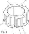
- Fig. 4 shows a further embodiment of the damping element, which is provided with the reference numeral 50.
- projections 57 are arranged, which protrude beyond the outer wall of the damping element 50 and tapering from the outer wall 51 to the end face 58 towards.
- the extensions 57 is a damping in the direction of - in FIG. 4 not shown - vehicle Z-axis reached.
- the extensions 57 are arranged offset at the opposite end faces 58, thereby the damping element can be produced inexpensively, since a simple demolding during production by means of a tool is possible.
- Another embodiment for damping in the direction of - in FIG. 4 not shown - vehicle Z-axis is to be attached to the encircling collar of in FIG. 4 not shown sleeve 41 or on the damping element facing side of in FIG. 4 Not shown end member 43 to arrange a soft component.
- the soft component is injection-molded in an injection mold onto the intended surfaces of the sleeve 41 or the closing element 43.
- the soft component may be formed as a knob or wedge or web, which are arranged circumferentially on the collar of the sleeve 41 or on the damping element 50 facing side of the closing element 43.
- the number of nubs or wedges or webs can vary.
- the base body 60 and the sleeve 42, the sleeve 41 and the end elements 43, 44 are preferably made of plastic, for example made of polyamide, which are optionally glass-reinforced and / or polytetrafluoroethylene (PTFE) component.
- plastics for example made of polyamide, which are optionally glass-reinforced and / or polytetrafluoroethylene (PTFE) component.
- PTFE polytetrafluoroethylene
Description
Die vorliegende Erfindung betrifft eine Vorrichtung zum lösbaren Anbinden eines Betätigungsgliedes an einen Geber oder Nehmer, beispielsweise an einen Schalthebel oder ein Getriebe eines Kraftfahrzeuges, mit einer Anbindungsstelle zum Festlegen des Betätigungsgliedes und einer Aufnahme zum Festlegen eines Anbindungselementes des Gebers oder Nehmers, wobei die Aufnahme ein im Wesentlichen ösenartiges äußeres Aufnahmeelement sowie ein darin angeordnetes inneres Aufnahmeelement aufweist, zwischen denen ein elastisches Dämpfungselement angeordnet ist.
Die Erfindung betrifft ferner ein Betätigungsglied mit einer derartigen Anbindevorrichtung.
Anbindevorrichtungen der eingangs genannten Art sind beispielsweise aus
The invention further relates to an actuator with such a tether.
Tying devices of the type mentioned are, for example
Weitere Anbindungsvorrichtungen der eingangs genannten Art sind auch aus der
Die
Eine Anbindungsvorrichtung mit einer Aufnahme mit einem äußeren Aufnahmeelement und ein darin angeordnetes inneres Aufnahmeelement, zwischen denen ein elastisches Dämpfungselement angeordnet ist, offenbart auch die
Aus der
Trotz eines derartigen Dämpfungselementes zeigen die aus dem Stand der Technik bekannten Anbindevorrichtungen - gemessen am heutigen Fahrkomfort von Kraftfahrzeugen - häufig noch unzureichende Vibrationsunterdrückungseigenschaften. Dies gilt auch gemessen am heutigen Geräuschkomfort.Despite such a damping element known from the prior art tethering - measured on today's ride comfort of motor vehicles - often still insufficient vibration suppression properties. This also applies to today's noise comfort.
Aufgabe der vorliegenden Erfindung ist es daher, eine Anbindevorrichtung sowie ein Betätigungsglied mit einer Anbindungsvorrichtung der eingangs genannten Art dahingehend zu verbessern, dass die Übertragung von unerwünschten Vibrationen vom Getriebe über das Betätigungsglied in den Innenraum des Fahrzeuges auf ein Minimum reduziert wird. Gleichzeitig soll die Anbindung des Betätigungsgliedes an die Anbindevorrichtung technisch vereinfacht werden.Object of the present invention is therefore to improve a tether and an actuator with a connection device of the type mentioned in that the transmission of unwanted vibrations from the transmission via the actuator in the interior of the vehicle is reduced to a minimum. At the same time the connection of the actuator to the tethering device should be technically simplified.
Diese Aufgabe wird mit einer Vorrichtung gemäß Anspruch 1 sowie mit einem Betätigungsglied gemäß Anspruch 18 gelöst. Vorteilhafte Ausgestaltungen der Erfindung sind Gegenstand der Unteransprüche.This object is achieved with a device according to claim 1 and with an actuator according to claim 18. Advantageous embodiments of the invention are the subject of the dependent claims.
Die Vorrichtung zum lösbaren Anbinden eines Betätigungsgliedes an einen Geber oder Nehmer gemäß Obergriffs des Anspruchs 1 zeichnet sich dadurch aus, dass das Dämpfungselement als separates Bauteil ausgebildet ist und an seiner dem äußeren oder inneren Aufnahmeelement zugewandten Wandung ein periodisch und/oder alternierend ausgebildetes Wellenprofil und die Anbindungsstelle einen Gewindeeinsatz zum Festlegen des Betätigungsgliedes aufweist.The device for releasably connecting an actuator to a donor or taker according to the preamble of claim 1 is characterized in that the damping element is designed as a separate component and on its outer or inner receiving element facing wall a periodically and / or alternately formed wave profile and the Connection point has a threaded insert for fixing the actuator.
Erfindungsgemäß wurde erkannt, dass ein Dämpfungselement, welches zwischen dem inneren und dem äußeren Aufnahmeelement der Anbindevorrichtung angeordnet ist und eine wellenprofilartige Außenwandung, das heißt ein Wellenprofil, zum äußeren Aufnahmeelement hin aufweist, deutlich verbesserte Dämpfungseigenschaften besitzt, was die unerwünschte Übertragung von Vibrationen auf das Übertragungsglied betrifft. Grund hierfür ist u.a., dass durch das Profil, insbesondere Wellenprofil die Kontaktfläche des Dämpfungselementes zum äußeren Aufnahmeelement hin derart minimiert ist, dass die Übertragung von störenden Vibrationen in vorteilhafter Weise unterdrückt wird.According to the invention it has been recognized that a damping element, which is arranged between the inner and the outer receiving element of the tether and a wave profile-like outer wall, that is a Wavy profile, the outer receiving element out, has significantly improved damping properties, which relates to the unwanted transmission of vibrations to the transmission member. The reason for this is, inter alia, that the contact surface of the damping element to the outer receiving element is minimized by the profile, in particular wave profile out so that the transmission of disturbing vibrations is suppressed in an advantageous manner.
Auf Grund der Unterdrückung von störenden Vibrationen ist es möglich, die Anbindung des Betätigungsgliedes an die Anbindevorrichtung in erfindungsgemäßer Weise zu erleichtern, indem die Anbindestelle der Anbindevorrichtung einen Gewindeeinsatz aufweist, an dem in vorteilhafter Weise das Betätigungsglied mittels einer Schraube festgelegt werden kann. Im Vergleich zum Stand der Technik, bei dem das Betätigungsglied entweder direkt in die Anbindungsstelle eingespritzt wird, erlaubt ein Gewindeeinsatz eine kostengünstige, flexible und insbesondere wieder lösbare Anbindung des Betätigungsgliedes an die Anbindevorrichtung.Due to the suppression of disturbing vibrations, it is possible to facilitate the connection of the actuator to the tether in accordance with the invention, by the Anbindestelle the tether has a threaded insert on which advantageously the actuator can be fixed by means of a screw. In comparison to the prior art, in which the actuator is injected either directly into the connection point, a threaded insert allows a cost-effective, flexible and in particular again releasable connection of the actuator to the tether.
Gemäß einer ersten vorteilhaften Ausgestaltung der Erfindung ist das Profil auf der Außenwandung des Dämpfungselementes periodisch ausgebildet und/oder aus alternierend teilkreisförmigen, insbesondere halbkreisförmigen Fortsätzen und Vertiefungen gebildet. In Versuchen hat sich nämlich herausgestellt, dass durch ein derart ausgebildetes Wellenprofil die Dämpfungseigenschaften besonders effektiv verbessert werden.According to a first advantageous embodiment of the invention, the profile is periodically formed on the outer wall of the damping element and / or formed of alternating part-circular, in particular semicircular extensions and depressions. In tests, it has been found that the damping properties are particularly effectively improved by a wave profile designed in this way.
Um das Zusammenfügen der Anbindeeinrichtung bzw. des Einfügung des Dämpfungselementes zwischen das äußere ösenartige Ausnahmeelement und das darin aufgenommene innere Aufnahmeelement zu erleichtern, ist wenigstens eine der Umrandungen bzw. Kanten des Dämpfungselementes bei einer weiteren vorteilhaften Ausgestaltung der Erfindung abgefasst, insbesondere abgekantet oder abgerundet.In order to facilitate the joining of the Anbindeeinrichtung or the insertion of the damping element between the outer eyelet-like exception element and the inner receiving element received therein, at least one of the edges or edges of the damping element is in a further advantageous embodiment of the invention, in particular bevelled or rounded.
Für eine automatisierte Montage der Anbindeeinrichtung ist es vorteilhaft, wenn das Dämpfungselement als zylindrisches, ringförmiges Bauteil ausgebildet ist.For an automated assembly of the attachment device, it is advantageous if the damping element is designed as a cylindrical, annular component.
Eine besonders kostengünstige und stabile Anbindevorrichtung wird dadurch erreicht, dass das äußere Aufnahmeelement und die Anbindungsstelle einstückig, insbesondere als ein gemeinsamer Grundkörper, ausgebildet sind.A particularly cost-effective and stable tying device is achieved in that the outer receiving element and the connection point are integrally formed, in particular as a common base body.
Um einen Ausgleich von Winkelbewegungen zwischen dem Betätigungsglied und dem Anbindungselement des Gebers oder Nehmers zu gewährleisten, ist es nach einer weiteren vorteilhaften Ausgestaltung der Erfindung vorgesehen, dass das äußere Aufnahmeelement, das innere Aufnahmeelement und/oder das Dämpfungselement im Wesentlichen ringförmig und/oder hohlzylinderförmig ausgebildet sind. Hierdurch wird insbesondere eine Rotationsbewegung der Anbindevorrichtung bzw. des Betätigungsgliedes relativ zum Anbindungselement des Gebers oder Nehmers um die Längs- bzw. Rotationsachse des ösenartigen äußeren Aufnahmeelementes ermöglicht.In order to ensure a compensation of angular movements between the actuator and the connection element of the transmitter or receiver, it is provided according to a further advantageous embodiment of the invention that the outer receiving element, the inner receiving element and / or the damping element is substantially annular and / or hollow cylindrical are. In this way, in particular a rotational movement of the tethering device or of the actuating element relative to the connecting element of the transmitter or receiver is made possible around the longitudinal or rotational axis of the eye-like outer receiving element.
Eine besonders leichte und insbesondere wieder lösbare Verbindung zwischen Anbindungseinrichtung und Anbindungselement wird dadurch erreicht, dass gemäß einer weiteren vorteilhaften Ausgestaltung der Erfindung das innere Aufnahmeelement eine Buchse aufweist, in der das Anbindungselement des Gebers oder Nehmers, insbesondere mittels einer Rast- und/oder Knipsverbindung, festlegbar ist.A particularly lightweight and in particular detachable connection between the connection device and connection element is achieved in that according to a further advantageous embodiment of the invention, the inner receiving element has a socket in which the connection element of the encoder or receiver, in particular by means of a latching and / or Knipsverbindung, is determinable.
Um die Rotationsbewegungsfreiheitsgrade der Anbindevorrichtung bzw. des Betätigungsgliedes relativ zum Anbindungselement des Gebers und/oder Nehmers auf drei Achsen zu erweitern, kann es in vorteilhafter Weise vorgesehen sein, dass die Buchse als Gelenkpfanne eines Kugelgelenks ausgebildet ist, in der ein einen Kugelkopf aufweisendes Anbindungselementes des Gebers oder Nehmers festlegbar, insbesondere einrastbar oder einklipsbar ist.In order to extend the rotational movement degrees of freedom of the tether or of the actuator relative to the connecting element of the encoder and / or receiver on three axes, it may be provided in an advantageous manner that the socket is formed as a socket of a ball joint in which a ball head exhibiting a connecting element of Encoder or receiver can be fixed, in particular latched or clipped.
Darüber hinaus kann es vorgesehen sein, dass das innere Aufnahmeelement eine vorzugsweise zylinderförmige Hülse aufweist, in der die Buchse angeordnet ist. Ein derartiger zweiteiliger Aufbau aus Hülse und darin aufgenommener Buchse erlaubt es, das innere Aufnahmeelement einerseits mittels der Buchse an die Form des Anbindungselementes und andererseits über die Hülse an die Form des äußeren Aufnahmeelementes anzupassen. Hierdurch wird die Anbindungsvorrichtung insgesamt flexibel an verschiedene Geber bzw. Nehmer adaptierbar.In addition, it can be provided that the inner receiving element has a preferably cylindrical sleeve in which the socket is arranged. Such a two-part construction of sleeve and socket accommodated therein allows the inner receiving element to be adapted, on the one hand, to the shape of the connecting element by means of the bush and, on the other hand, via the sleeve to the shape of the outer receiving element. As a result, the connection device as a whole can be flexibly adapted to different encoders or receivers.
Zur Festlegung der Buchse in Montagestellung in wenigstens einer axialen Richtung innerhalb der Hülse ist es nach einer weiteren vorteilhaften Ausgestaltung der Erfindung vorgesehen, dass die Hülse eine Durchgangsverjüngung aufweist, mittels derer die vorzugsweise sich korrespondierend verjüngende Buchse durch Formfluss in Eingriff steht.For fixing the bushing in the assembly position in at least one axial direction within the sleeve, it is provided according to a further advantageous embodiment of the invention that the sleeve has a passage taper, by means of which the preferably correspondingly tapered bushing is engaged by molding flow.
Nach einer weiteren vorteilhaften Ausgestaltung der Erfindung ist es vorgesehen, dass das innere Aufnahmeelement in axialer Richtung bezüglich des ösenartigen äußeren Aufnahmeelementes jeweils endseitig ein Abschlusselement aufweist, mittels dessen das innere Aufnahmeelement, insbesondere die Hülse und/oder die Buchse, in axialer Richtung am äußeren Aufnahmeelement festgelegt ist.According to a further advantageous embodiment of the invention, it is provided that the inner receiving element in the axial direction relative to the eyelet-shaped outer receiving element each end has a closing element, by means of which the inner receiving element, in particular the sleeve and / or the sleeve, in the axial direction on the outer receiving element is fixed.
Besonders bevorzug ist die Buchse und wenigstens eines der beiden Abschlusselemente einstückig, insbesondere als Hohlzylinder mit einem einenends umlaufendem Bund oder Flansch, ausgebildet.Particularly preferably, the socket and at least one of the two end elements in one piece, in particular as a hollow cylinder with a one-round circumferential collar or flange formed.
Vorzugsweise sind die jeweiligen endseitigen Abschlusselemente derart ausgebildet, dass sie größere radiale Ausdehnung aufweisen als die Hülse oder die Buchse, so dass mittels Formfluss eine axiale Festlegung des inneren Aufnahmeelementes über das stirnseitig bzw. auf einer Flachseite am äußeren Aufnahmeelement anliegende Abschlusselement erreicht wird. Denkbar ist beispielsweise, dass wenigstens eines der beiden Abschlusselemente deckel- oder teller- oder lochscheibenartig ausgebildet ist. Die lochscheibenartige Ausbildung bietet sich insbesondere für jene Seite des inneren bzw. äußeren Aufnahmeelementes an, über die das Anbindungselement, insbesondere der Kugelgelenkkopf, in die Buchse eingeführt wird.Preferably, the respective end-side termination elements are formed such that they have greater radial extent than the sleeve or the socket, so that by means of shape flow axial fixing of the inner receiving element via the front side or on a flat side on the outer receiving element fitting end element is achieved. It is conceivable, for example, that at least one of the two end elements is formed lid or plate or disc-like. The hole-disc-like design is particularly suitable for that side of the inner or outer Receiving element, via which the connection element, in particular the ball joint head, is inserted into the socket.
Zur Fixierung der Abschlusselemente an der Hülse ist nach einer weiteren vorteilhaften Ausgestaltung der Erfindung vorgesehen, dass wenigstens eines der beiden Abschlusselemente eine stirnseitig umlaufende Nut aufweist, in welche die Hülse in Montagestellung eingreift. Denkbar ist beispielsweise, dass die Hülse in die umlaufende Nut eingepresst, eingeklebt oder eingeklipst wird.For fixing the end elements to the sleeve is provided according to a further advantageous embodiment of the invention, that at least one of the two end elements has a frontally circumferential groove into which the sleeve engages in the assembled position. It is conceivable, for example, that the sleeve is pressed into the circumferential groove, glued or clipped.
Gemäß einer weiteren vorteilhaften Ausgestaltung der Erfindung ist der Gewindeeinsatz als Mutter, insbesondere als Mehrkantmutter, ausgebildet. Hierbei kann insbesondere auf Standartbauelemente zurückgegriffen werden, was sich in vorteilhafter Weise auf die Herstellungskosten der Anbindungsvorrichtung auswirkt.According to a further advantageous embodiment of the invention, the threaded insert is designed as a nut, in particular as a polygonal nut. In this case, in particular standard components can be used, which has an advantageous effect on the manufacturing cost of the connection device.
Um die Anbindung des Betätigungsgliedes an die Anbindungsstelle technisch weiter zu vereinfachen, insbesondere eine wohl definierte Anbindung zu gewährleisten, ist es nach einer weiteren vorteilhaften Ausgestaltung der Erfindung vorgesehen, dass die Anwendungsstelle eine Auflage und/oder eine Führung für das anzubindende Betätigungsglied, insbesondere für eine Anschlusslasche eines anzubindenden Betätigungsgliedes aufweist.To further simplify the connection of the actuator to the connection point technically, in particular to ensure a well-defined connection, it is provided according to a further advantageous embodiment of the invention that the application point a support and / or a guide for the actuator to be connected, in particular for a Connecting lug to be connected to an actuator.
Ein unabhängiger Gedanke der Erfindung betrifft ein Betätigungsglied mit wenigstens einer einenends, vorzugsweise im Bereich einer Anschlusslasche, angeordneten Anbindungsvorrichtung der zuvor beschriebenen Art.An independent idea of the invention relates to an actuating member having at least one connecting device, of the kind previously described, arranged at one end, preferably in the region of a connecting lug.
Nach einer weiteren vorteilhaften Ausgestaltung ist es vorgesehen, dass die Achse des Gewindeeinsatzes bzw. der Mutter orthogonal zur Achse der Aufnahme verläuft. Dadurch ergeben sich Vorteile bei der Montage und Einstellung der Vorrichtung in einem Kraftfahrzeug, da der Werkzeugangriff in einer im Wesentlichen horizontalen Ebene liegt.According to a further advantageous embodiment, it is provided that the axis of the threaded insert or the nut is orthogonal to the axis of the receptacle. This results in advantages in the assembly and adjustment of the device in a motor vehicle, since the tool attack is in a substantially horizontal plane.
Nach einer besonders vorteilhaften Ausgestaltung des Betätigungsgliedes ist es vorgesehen, dass wenigstens einenends, vorzugsweise im Bereich einer Anschlusslasche, ein Loch, insbesondere ein Langloch, vorgesehen ist, durch das zum Festlegen des Betätigungsgliedes an der Vorrichtung eine Schraube in den Gewindeeinsatz eindrehbar ist. Eine weitere vorteilhafte Ausgestaltung der Erfindung sieht vor, dass das Dämpfungselement als separat handhabbares Bauteil ausgebildet ist.According to a particularly advantageous embodiment of the actuator, it is provided that at least one end, preferably in the region of a terminal lug, a hole, in particular a slot, is provided, through which a screw in the threaded insert can be screwed for fixing the actuator to the device. A further advantageous embodiment of the invention provides that the damping element is designed as a separately manageable component.
Weitere Ziele, Vorteile, Merkmale und Anwendungsmöglichkeiten der vorliegenden Erfindung ergeben sich aus der nachfolgenden Beschreibung eines Ausführungsbeispieles anhand der Zeichnung. Dabei bilden alle beschriebenen und/oder bildlich dargestellten Merkmale für sich oder in beliebiger sinnvoller Kombination den Gegenstand der vorliegenden Erfindung, auch unabhängig von ihrer Zusammenfassung in den Ansprüchen oder deren Rückbeziehung.Other objects, advantages, features and applications of the present invention will become apparent from the following description of an embodiment with reference to the drawings. All described and / or illustrated features alone or in any meaningful combination form the subject matter of the present invention, also independent of their summary in the claims or their dependency.
Es zeigen:
- Fig. 1
- eine Explosionsdarstellung eines möglichen Ausführungsbeispiels einer erfindungsgemäßen Vorrichtung zum lösbaren Anbinden eines Betätigungsgliedes an einem Geber oder Nehmer,
- Fig. 2
- einen Längsschnitt durch die zusammengefügte Vorrichtung gemäß
Fig. 1 und - Fig. 3
- eine Draufsicht auf das Dämpfungselement der Vorrichtung gemäß
Fig. 1 . - Fig. 4
- eine perspektivische Ansicht einer weiteren Ausführungsform des Dämpfungselements.
- Fig. 1
- an exploded view of a possible embodiment of an inventive device for releasably connecting an actuator to a donor or taker,
- Fig. 2
- a longitudinal section through the assembled device according to
Fig. 1 and - Fig. 3
- a plan view of the damping element of the device according to
Fig. 1 , - Fig. 4
- a perspective view of another embodiment of the damping element.
Die
In vorteilhafter Weise sind bei dem in den
Wie den
Bei dem in den
Desweiteren ist die Buchse 42 bei dem vorliegenden Ausführungsbeispiel in einer zylinderförmig ausgebildeten Hülse 41 aufgenommen, welche eine Durchgangsverjüngung 46 aufweist, mittels derer die sich korrespondierende verjüngende Buchse 42 in Montagestellung in einer axialen Richtung innerhalb der Hülse 41 festgelegt ist.Furthermore, the
In entgegengesetzter axialer Richtung ist die Buchse 42 in Hülse 41 durch das tellerartige Abschlusselement 43 festgelegt, das stirnseitig eine umlaufende Nut 45 aufweist, in welche die Hülse 41 in Montagestellung eingreift. Das Abschlusselement 43 besitzt in radialer Richtung eine größere Ausdehnung als die Hülse 41 und gelangt mit dem überlappenden Bereich in Anlagestellung mit dem äußeren Aufnahmeelement 30, wodurch das innere Aufnahmeelement 40 gegenüber dem äußeren Aufnahmeelement 30 in einer axialen Richtung mittels Formschluss festgelegt ist.In the opposite axial direction, the
Auf der gegenüberliegenden Seite des tellerartigen Abschlusselementes 43 ist ein weiteres Abschlusselement 44 vorgesehen, welches im vorliegenden Ausführungsbeispiel einstückig mit der Hülse 41 ausgebildet ist. Hülse 41 und Abschlusselement 44 bilden zusammen einen Hohlzylinder, der einen umlaufenden Bund oder Flansch aufweist, welcher durch das lochscheibenartige Abschlusselement 44 gebildet ist. Durch die Öffnung des lochscheibenartigen Aufnahmeelements 44 wird ein Zugang geschaffen, über den das Anbindungselement des Gebers oder Nehmers in die Buchse 42 einführbar ist.On the opposite side of the plate-
Wie den
Zum Festlegen des Betätigungsgliedes an der Anbindungsstelle 10 ist es gemäß der Erfindung vorgesehen, dass die Anbindungsstelle 10 einen Gewindeeinsatz 11 aufweist. Im hier gezeigten Ausführungsbeispiel ist der Gewindeeinsatz 11 eine mehrkantige Stanzmutter 12, die im Querschnitt im Wesentlichen trapezförmig abgebildet ist. Ferner ist den
Um eine Längeneinstellung des anzubindenden, hier nicht dargestellten Betätigungsgliedes zu gewährleisten, kann es weiterhin vorgesehen sein, dass das Betätigungsglied, insbesondere im Bereich der Anschlusslasche, ein Langloch aufweist, wodurch eine stufenlose Einstellung und Vorfixierung der Anbindevorrichtung 1 am Betätigungsglied möglich ist.In order to ensure a length adjustment of the to be connected, not shown actuator, it may further be provided that the actuator, in particular in the region of the terminal lug, has a slot, whereby a continuous adjustment and pre-fixing the tether 1 on the actuator is possible.
Wie insbesondere den
Um auch eine Dämpfung in Richtung aller drei Fahrzeugachsen, insbesondere auch der bzgl. des Fahrzeuges nach oben gerichteten Z-Achse bzw. der Fahrzeughochachse zu erhalten, können nach einem eigenständigen Aspekt der Erfindung an den Stirnseiten des Dämpfungselements Fortsätze oder profilierte Endabschnitte vorgesehen sein. Bspw. ist dazu an wenigstens einer Stirnfläche des Dämpfungselements ein umlaufender, ringförmiger Fortsatz angeordnet. Dabei hat es sich als vorteilhaft herausgestellt, wenn der Durchmesser des ringförmigen Fortsatzes größer als die Wandstärke des zylindrischen Teils des Dämpfungselementes (50) ist.In order to obtain an attenuation in the direction of all three vehicle axles, in particular also with respect to the vehicle upwardly directed Z-axis or the vehicle vertical axis, extensions or profiled end sections can be provided according to an independent aspect of the invention on the end faces of the damping element. For example. For this purpose, a circumferential, annular extension is arranged on at least one end face of the damping element. It has been found to be advantageous if the diameter of the annular extension is greater than the wall thickness of the cylindrical portion of the damping element (50).
Eine weitere Ausgestaltung für eine Dämpfung in Richtung der - in
Die Herstellung einer derart gestalteten Hülse oder eines Abschlusselements ist aus dem Stand der Technik bekannt und erfolgt z.B. als 2K-Bauteil. Dies bedeutet, dass die Weichkomponente in einer Spritzgussform an die vorgesehenen Flächen der Hülse 41 oder des Abschlusselements 43 angespritzt wird.
Die Weichkomponente kann dabei als Noppe oder Keil oder Steg ausgebildet sein, die umlaufend an dem Bund der Hülse 41 oder an der dem Dämpfungselement 50 zugewandten Seite des Abschlusselements 43 angeordnet sind. Dabei kann die Anzahl der Noppen oder Keile oder Stege variieren.The production of such a shaped sleeve or a terminating element is known from the prior art and takes place for example as a 2K component. This means, the soft component is injection-molded in an injection mold onto the intended surfaces of the
The soft component may be formed as a knob or wedge or web, which are arranged circumferentially on the collar of the
Demgegenüber sind der Grundkörper 60 sowie die Buchse 42, die Hülse 41 und die Abschlusselemente 43, 44 vorzugsweise aus Kunststoff, beispielsweise aus Polyamid gefertigt, die gegebenenfalls glaserverstärkt sind und/oder Polytetrafluorethylen (PTFE)-Bestandteil aufweisen. Die Verwendung solcher Kunststoffe ist hinsichtlich einer Gewichtseinsparung als auch unter fertigungstechnischen Gesichtspunkten von besonderem Vorteil.In contrast, the
- 11
- AnbindevorrichtungTying
- 1010
- Anbindungsstelleconnecting point
- 1111
- Gewindeeinsatzthreaded insert
- 1212
- Muttermother
- 1313
- Auflageedition
- 1414
- Führungguide
- 2020
- Aufnahmeadmission
- 3030
- äußeres Aufnahmeelementouter receiving element
- 4040
- inneres Aufnahmeelementinner receptacle
- 4141
- Hülseshell
- 4242
- BuchseRifle
- 4343
- Abschlusselementtermination element
- 4444
- Abschlusselementtermination element
- 4545
- Nutgroove
- 5050
- Dämpfungselementdamping element
- 5151
- Außenwandung des DämpfungselementesOuter wall of the damping element
- 5252
- Wellenprofilwave profile
- 5353
- Fortsatzextension
- 5454
- Vertiefungdeepening
- 5555
- Berandungboundary
- 5656
- Berandungboundary
- 5757
- Fortsatzextension
- 5858
- Stirnseitefront
- 6060
- Grundkörperbody
Claims (20)
- Device (1) for releasably linking an actuating member to a transducer or receiver, for example to a switch lever or a gear box of a motor vehicle, with a linking site (10) for fixedly attaching the actuating member, and a reception area (20) for fixedly attaching a linking element of the transducer or the receiver, wherein the reception area (20) has a substantially loop-like outer reception element (30) as well as an inner reception element (40) that is arranged therein, between which an elastic damping element (50) is arranged, characterized in that the damping element (50) is embodied as a separate structural component and at its wall (51) that is facing the outer or the inner reception element (30, 40) has a periodically and/or alternatingly embodied profile in the form of a wave profile (52), and the linking site (10) has an thread insert (11) for fixedly attaching the actuating member.
- Device (1) according to claim 1, characterized in that the profile, in particular the wave profile (52), is embodied in a periodic manner and/or is formed of alternating extensions (53) and indentations (54) that have the shape of a partial circle, in particular of a semicircle.
- Device (1) according to claim 1 or 2,
characterized in that at least one boundary (55, 56) of the damping element (50) is chamfered, in particular beveled or rounded. - Device (1) according to one of the preceding claims, characterized in that the outer reception element (30) and the linking site (10) are embodied in one piece, in particular as a common base body (60).
- Device (1) according to one of the preceding claims, characterized in that the outer reception element (30), the inner reception element (40) and/or the damping element (50) are embodied substantially in the shape of a ring and/or a hollow cylinder.
- Device (1) according to one of the preceding claims, characterized in that the inner reception element (40) has a bushing (42) inside of which the linking element of the transducer or the receiver can be fixedly attached, in particular by means of a snap-in and/or clip connection.
- Device (1) according to claim 6, characterized in that the bushing (42) is embodied as a socket of a ball joint, inside of which a linking element of the transducer or the receiver having a spherical head can be fixedly attached, in particular snapped in or clipped in.
- Device (1) according to claim 6 or 7,
characterized in that the inner reception element (40) has a preferably cylindrical sleeve (41) inside of which the bushing (42) is arranged. - Device (1) according to claim 8, characterized in that the sleeve (41) has a passage tapering by means of which the bushing (42), which is preferably correspondingly tapered, is fixedly attached inside the sleeve (41) in the mounting position in at least one axial direction.
- Device (1) according to any of the preceding claims, characterized in that the inner reception element (40) respectively has an end element (43, 44) at the end side in the axial direction with respect to the lop-like outer reception element (30), by means of which the inner reception element (40), in particular the sleeve (41) and/or the bushing (42), is fixedly attached at the outer reception element (30) in the axial direction.
- Device (1) according to claim 10, characterized in that the bushing (42) and at least one of the two end elements (43, 44) is embodied in one piece, in particular as a hollow cylinder with a collar or flange extending circumferentially at one end.
- Device (1) according to claim 10 or 11,
characterized in that at least one of the two end elements (43, 44) is embodied in the manner of a lid or a plate or a perforated disc. - Device (1) according to any of the claims 10 to 12, characterized in that at least one of the two end elements (43, 44) has a circumferential grove (45) with which the sleeve (41) meshes in the mounting position.
- Device (1) according to any of the preceding claims, characterized in that the thread insert (11) is a nut (12), in particular a polygonal nut.
- Device according to any of the preceding claims 1 to 14, characterized in that the axis of the thread insert (11) is arranged orthogonally with respect to the axis of the reception area (20).
- Device (1) according to any of the preceding claims, characterized in that the thread insert (11) is integrated in the linking site (10), in particular in the base body (60), by means of overmolding.
- Device (1) according to any of the preceding claims, characterized in that the linking site (10) has a support (13) and/or a guide (14) for the actuating member to be linked, in particular for a connection lug of an actuating member to be linked.
- Actuating member with at least one device (1) according to any of the preceding claims that is arranged at one end, preferably in the area of a connection lug.
- Actuating member according to claim 18,
characterized in that
at least at one end, preferably in the area of a connection lug, a hole, in particular an oblong hole, is provided, through which a screw can be screwed into the threaded element (11) for fixedly attaching the actuating member at the device (1). - Device according to one of the preceding claims 1 to 19, characterized in that a circumferential, ringshaped extension is arranged at least at one front surface of the damping element (50).
Applications Claiming Priority (2)
| Application Number | Priority Date | Filing Date | Title |
|---|---|---|---|
| DE202013104768U DE202013104768U1 (en) | 2013-10-23 | 2013-10-23 | Device for detachably connecting an actuator to a transmitter or receiver |
| PCT/EP2014/072345 WO2015059056A1 (en) | 2013-10-23 | 2014-10-17 | Device for removable securing of an actuating member to an input or output element |
Publications (2)
| Publication Number | Publication Date |
|---|---|
| EP2962003A1 EP2962003A1 (en) | 2016-01-06 |
| EP2962003B1 true EP2962003B1 (en) | 2018-03-14 |
Family
ID=49781044
Family Applications (1)
| Application Number | Title | Priority Date | Filing Date |
|---|---|---|---|
| EP14786660.2A Active EP2962003B1 (en) | 2013-10-23 | 2014-10-17 | Device for detachably fastening an actuating element to a transmitter or receiver |
Country Status (8)
| Country | Link |
|---|---|
| US (2) | US20160245332A1 (en) |
| EP (1) | EP2962003B1 (en) |
| JP (1) | JP6397905B2 (en) |
| KR (1) | KR102102503B1 (en) |
| CN (1) | CN105683595B (en) |
| DE (1) | DE202013104768U1 (en) |
| ES (1) | ES2672742T3 (en) |
| WO (1) | WO2015059056A1 (en) |
Families Citing this family (2)
| Publication number | Priority date | Publication date | Assignee | Title |
|---|---|---|---|---|
| US10988015B2 (en) * | 2018-12-06 | 2021-04-27 | GM Global Technology Operations LLC | Multi-position mount system |
| CN112682419B (en) * | 2021-03-16 | 2021-05-18 | 长岛高能聚氨酯有限公司 | Aluminum joint ball pin assembly and production process thereof |
Citations (1)
| Publication number | Priority date | Publication date | Assignee | Title |
|---|---|---|---|---|
| DE19755284A1 (en) * | 1997-12-22 | 1999-06-24 | Schaeffler Waelzlager Ohg | Ball and socket joint for e.g. gear shift linkage |
Family Cites Families (12)
| Publication number | Priority date | Publication date | Assignee | Title |
|---|---|---|---|---|
| US2710208A (en) * | 1952-11-18 | 1955-06-07 | Columbus Auto Parts | Universal joint |
| US3350042A (en) * | 1965-10-11 | 1967-10-31 | Clevite Corp | Corrugated resilient mount |
| JPS5125902B2 (en) * | 1972-01-28 | 1976-08-03 | ||
| JPS5137365A (en) * | 1974-09-27 | 1976-03-29 | Toshio Hata | |
| JPH01150242U (en) * | 1988-04-11 | 1989-10-17 | ||
| JPH0720739Y2 (en) * | 1989-06-20 | 1995-05-15 | オイレス工業株式会社 | Bearing structure of pedal arm |
| US5265495A (en) * | 1992-09-21 | 1993-11-30 | Teleflex Incorporated | Isolated shifter terminal assembly |
| DE10127630C2 (en) * | 2000-06-13 | 2003-04-30 | Kuester Automotive Control Sys | Device for length adjustment, in particular remote control in motor vehicles |
| DE10206085B4 (en) * | 2002-02-13 | 2004-02-05 | Dura Automotive Systems Gmbh | Connection device for an angle joint |
| JP4145739B2 (en) * | 2003-07-01 | 2008-09-03 | 本田技研工業株式会社 | Anti-vibration ball joint |
| FR2895042B1 (en) * | 2005-12-15 | 2008-02-29 | Dura Automotive Systems Soc Pa | BALL JOINT DEVICE BETWEEN TWO ELEMENTS OF A MECHANICAL TRANSMISSION |
| EP2278178B1 (en) | 2009-07-14 | 2013-02-27 | Fulvio Orsolini | Ball joint for connecting mechanical elements |
-
2013
- 2013-10-23 DE DE202013104768U patent/DE202013104768U1/en not_active Expired - Lifetime
-
2014
- 2014-10-17 KR KR1020167011327A patent/KR102102503B1/en active IP Right Grant
- 2014-10-17 JP JP2016520155A patent/JP6397905B2/en active Active
- 2014-10-17 WO PCT/EP2014/072345 patent/WO2015059056A1/en active Application Filing
- 2014-10-17 US US15/027,542 patent/US20160245332A1/en not_active Abandoned
- 2014-10-17 CN CN201480058704.2A patent/CN105683595B/en active Active
- 2014-10-17 EP EP14786660.2A patent/EP2962003B1/en active Active
- 2014-10-17 ES ES14786660.2T patent/ES2672742T3/en active Active
-
2019
- 2019-08-14 US US16/540,120 patent/US11187263B2/en active Active
Patent Citations (1)
| Publication number | Priority date | Publication date | Assignee | Title |
|---|---|---|---|---|
| DE19755284A1 (en) * | 1997-12-22 | 1999-06-24 | Schaeffler Waelzlager Ohg | Ball and socket joint for e.g. gear shift linkage |
Also Published As
| Publication number | Publication date |
|---|---|
| US20160245332A1 (en) | 2016-08-25 |
| KR20160073973A (en) | 2016-06-27 |
| CN105683595B (en) | 2019-05-28 |
| KR102102503B1 (en) | 2020-04-21 |
| WO2015059056A1 (en) | 2015-04-30 |
| EP2962003A1 (en) | 2016-01-06 |
| JP2016533938A (en) | 2016-11-04 |
| ES2672742T3 (en) | 2018-06-15 |
| CN105683595A (en) | 2016-06-15 |
| DE202013104768U1 (en) | 2013-11-19 |
| JP6397905B2 (en) | 2018-09-26 |
| US11187263B2 (en) | 2021-11-30 |
| US20190368537A1 (en) | 2019-12-05 |
Similar Documents
| Publication | Publication Date | Title |
|---|---|---|
| EP3077684B1 (en) | Annular plug coupling, and production method and connection method therefor | |
| WO2012072340A1 (en) | Wiper drive | |
| EP1925831A2 (en) | Oscillation-decoupling coupling element | |
| EP2037292A2 (en) | Mounting device for a rotation-sensitive component, in particular an ultrasound converter, and method for mounting the component | |
| WO1996020101A1 (en) | Windshield wiper assembly with a noise- and vibration-damping fastener | |
| EP3692269A1 (en) | Angle coupling | |
| DE102021118920A1 (en) | tolerance compensation device | |
| WO2001036903A1 (en) | Measuring rope-path sensor | |
| EP3585671B1 (en) | Bearing for a steering shaft and steering system for a vehicule | |
| DE102004021537A1 (en) | Electric motor and gear drive unit for actuators in the motor vehicle | |
| DE19901674B4 (en) | Shifter fork with plastic sliding shoes | |
| EP2962003B1 (en) | Device for detachably fastening an actuating element to a transmitter or receiver | |
| WO2012098108A1 (en) | Plate coupling | |
| DE10081629B4 (en) | CABLE MOUNTING | |
| DE102017103779B4 (en) | Elastic bearing | |
| DE102006019576B4 (en) | Steering device for vehicles and method for mounting a bearing assembly | |
| EP4030024B1 (en) | Motor vehicle lock | |
| EP1291536B1 (en) | Device for fastening an elongated element | |
| DE10216903B4 (en) | Connection device for an actuating cable to a slave, in particular towing eye | |
| EP2006171A2 (en) | Windscreen wiper actuator assembly | |
| EP3927594B1 (en) | Power-assisted steering system for a motor vehicle | |
| DE102012209058A1 (en) | Windscreen wiper device for motor car, has aperture whose internal diameter is slightly smaller than outer diameter of assembly region of socket pad such that pad is attached into device by simply inserting and clipping pad into opening | |
| EP3631130B1 (en) | Actuating drive for a motor vehicle | |
| DE102006019574A1 (en) | Steering device for vehicles | |
| DE102005053885A1 (en) | Actuator e.g. Bowden cable lug, connecting device for motor vehicle, has locking unit increasing removal force of master and/or slave from actuator, and bellows connection provided in area of connection between actuator and retainer frame |
Legal Events
| Date | Code | Title | Description |
|---|---|---|---|
| PUAI | Public reference made under article 153(3) epc to a published international application that has entered the european phase |
Free format text: ORIGINAL CODE: 0009012 |
|
| 17P | Request for examination filed |
Effective date: 20151002 |
|
| AK | Designated contracting states |
Kind code of ref document: A1 Designated state(s): AL AT BE BG CH CY CZ DE DK EE ES FI FR GB GR HR HU IE IS IT LI LT LU LV MC MK MT NL NO PL PT RO RS SE SI SK SM TR |
|
| AX | Request for extension of the european patent |
Extension state: BA ME |
|
| 17Q | First examination report despatched |
Effective date: 20160224 |
|
| DAX | Request for extension of the european patent (deleted) | ||
| GRAP | Despatch of communication of intention to grant a patent |
Free format text: ORIGINAL CODE: EPIDOSNIGR1 |
|
| INTG | Intention to grant announced |
Effective date: 20170925 |
|
| GRAS | Grant fee paid |
Free format text: ORIGINAL CODE: EPIDOSNIGR3 |
|
| GRAA | (expected) grant |
Free format text: ORIGINAL CODE: 0009210 |
|
| RIN1 | Information on inventor provided before grant (corrected) |
Inventor name: HENRICH, WILLI Inventor name: KREMER, VIKTOR |
|
| AK | Designated contracting states |
Kind code of ref document: B1 Designated state(s): AL AT BE BG CH CY CZ DE DK EE ES FI FR GB GR HR HU IE IS IT LI LT LU LV MC MK MT NL NO PL PT RO RS SE SI SK SM TR |
|
| REG | Reference to a national code |
Ref country code: GB Ref legal event code: FG4D Free format text: NOT ENGLISH |
|
| REG | Reference to a national code |
Ref country code: CH Ref legal event code: EP Ref country code: AT Ref legal event code: REF Ref document number: 979188 Country of ref document: AT Kind code of ref document: T Effective date: 20180315 |
|
| REG | Reference to a national code |
Ref country code: IE Ref legal event code: FG4D Free format text: LANGUAGE OF EP DOCUMENT: GERMAN |
|
| REG | Reference to a national code |
Ref country code: DE Ref legal event code: R096 Ref document number: 502014007645 Country of ref document: DE |
|
| REG | Reference to a national code |
Ref country code: ES Ref legal event code: FG2A Ref document number: 2672742 Country of ref document: ES Kind code of ref document: T3 Effective date: 20180615 |
|
| REG | Reference to a national code |
Ref country code: NL Ref legal event code: MP Effective date: 20180314 |
|
| REG | Reference to a national code |
Ref country code: LT Ref legal event code: MG4D |
|
| PG25 | Lapsed in a contracting state [announced via postgrant information from national office to epo] |
Ref country code: FI Free format text: LAPSE BECAUSE OF FAILURE TO SUBMIT A TRANSLATION OF THE DESCRIPTION OR TO PAY THE FEE WITHIN THE PRESCRIBED TIME-LIMIT Effective date: 20180314 Ref country code: LT Free format text: LAPSE BECAUSE OF FAILURE TO SUBMIT A TRANSLATION OF THE DESCRIPTION OR TO PAY THE FEE WITHIN THE PRESCRIBED TIME-LIMIT Effective date: 20180314 Ref country code: NO Free format text: LAPSE BECAUSE OF FAILURE TO SUBMIT A TRANSLATION OF THE DESCRIPTION OR TO PAY THE FEE WITHIN THE PRESCRIBED TIME-LIMIT Effective date: 20180614 Ref country code: HR Free format text: LAPSE BECAUSE OF FAILURE TO SUBMIT A TRANSLATION OF THE DESCRIPTION OR TO PAY THE FEE WITHIN THE PRESCRIBED TIME-LIMIT Effective date: 20180314 Ref country code: CY Free format text: LAPSE BECAUSE OF FAILURE TO SUBMIT A TRANSLATION OF THE DESCRIPTION OR TO PAY THE FEE WITHIN THE PRESCRIBED TIME-LIMIT Effective date: 20180314 |
|
| PG25 | Lapsed in a contracting state [announced via postgrant information from national office to epo] |
Ref country code: RS Free format text: LAPSE BECAUSE OF FAILURE TO SUBMIT A TRANSLATION OF THE DESCRIPTION OR TO PAY THE FEE WITHIN THE PRESCRIBED TIME-LIMIT Effective date: 20180314 Ref country code: LV Free format text: LAPSE BECAUSE OF FAILURE TO SUBMIT A TRANSLATION OF THE DESCRIPTION OR TO PAY THE FEE WITHIN THE PRESCRIBED TIME-LIMIT Effective date: 20180314 Ref country code: SE Free format text: LAPSE BECAUSE OF FAILURE TO SUBMIT A TRANSLATION OF THE DESCRIPTION OR TO PAY THE FEE WITHIN THE PRESCRIBED TIME-LIMIT Effective date: 20180314 Ref country code: GR Free format text: LAPSE BECAUSE OF FAILURE TO SUBMIT A TRANSLATION OF THE DESCRIPTION OR TO PAY THE FEE WITHIN THE PRESCRIBED TIME-LIMIT Effective date: 20180615 Ref country code: BG Free format text: LAPSE BECAUSE OF FAILURE TO SUBMIT A TRANSLATION OF THE DESCRIPTION OR TO PAY THE FEE WITHIN THE PRESCRIBED TIME-LIMIT Effective date: 20180614 |
|
| PG25 | Lapsed in a contracting state [announced via postgrant information from national office to epo] |
Ref country code: MT Free format text: LAPSE BECAUSE OF FAILURE TO SUBMIT A TRANSLATION OF THE DESCRIPTION OR TO PAY THE FEE WITHIN THE PRESCRIBED TIME-LIMIT Effective date: 20180314 |
|
| REG | Reference to a national code |
Ref country code: FR Ref legal event code: PLFP Year of fee payment: 5 |
|
| PG25 | Lapsed in a contracting state [announced via postgrant information from national office to epo] |
Ref country code: EE Free format text: LAPSE BECAUSE OF FAILURE TO SUBMIT A TRANSLATION OF THE DESCRIPTION OR TO PAY THE FEE WITHIN THE PRESCRIBED TIME-LIMIT Effective date: 20180314 Ref country code: AL Free format text: LAPSE BECAUSE OF FAILURE TO SUBMIT A TRANSLATION OF THE DESCRIPTION OR TO PAY THE FEE WITHIN THE PRESCRIBED TIME-LIMIT Effective date: 20180314 Ref country code: RO Free format text: LAPSE BECAUSE OF FAILURE TO SUBMIT A TRANSLATION OF THE DESCRIPTION OR TO PAY THE FEE WITHIN THE PRESCRIBED TIME-LIMIT Effective date: 20180314 Ref country code: PL Free format text: LAPSE BECAUSE OF FAILURE TO SUBMIT A TRANSLATION OF THE DESCRIPTION OR TO PAY THE FEE WITHIN THE PRESCRIBED TIME-LIMIT Effective date: 20180314 Ref country code: NL Free format text: LAPSE BECAUSE OF FAILURE TO SUBMIT A TRANSLATION OF THE DESCRIPTION OR TO PAY THE FEE WITHIN THE PRESCRIBED TIME-LIMIT Effective date: 20180314 |
|
| PG25 | Lapsed in a contracting state [announced via postgrant information from national office to epo] |
Ref country code: SK Free format text: LAPSE BECAUSE OF FAILURE TO SUBMIT A TRANSLATION OF THE DESCRIPTION OR TO PAY THE FEE WITHIN THE PRESCRIBED TIME-LIMIT Effective date: 20180314 Ref country code: CZ Free format text: LAPSE BECAUSE OF FAILURE TO SUBMIT A TRANSLATION OF THE DESCRIPTION OR TO PAY THE FEE WITHIN THE PRESCRIBED TIME-LIMIT Effective date: 20180314 Ref country code: SM Free format text: LAPSE BECAUSE OF FAILURE TO SUBMIT A TRANSLATION OF THE DESCRIPTION OR TO PAY THE FEE WITHIN THE PRESCRIBED TIME-LIMIT Effective date: 20180314 |
|
| REG | Reference to a national code |
Ref country code: DE Ref legal event code: R097 Ref document number: 502014007645 Country of ref document: DE |
|
| PG25 | Lapsed in a contracting state [announced via postgrant information from national office to epo] |
Ref country code: PT Free format text: LAPSE BECAUSE OF FAILURE TO SUBMIT A TRANSLATION OF THE DESCRIPTION OR TO PAY THE FEE WITHIN THE PRESCRIBED TIME-LIMIT Effective date: 20180716 |
|
| PLBE | No opposition filed within time limit |
Free format text: ORIGINAL CODE: 0009261 |
|
| STAA | Information on the status of an ep patent application or granted ep patent |
Free format text: STATUS: NO OPPOSITION FILED WITHIN TIME LIMIT |
|
| PG25 | Lapsed in a contracting state [announced via postgrant information from national office to epo] |
Ref country code: DK Free format text: LAPSE BECAUSE OF FAILURE TO SUBMIT A TRANSLATION OF THE DESCRIPTION OR TO PAY THE FEE WITHIN THE PRESCRIBED TIME-LIMIT Effective date: 20180314 |
|
| 26N | No opposition filed |
Effective date: 20181217 |
|
| PG25 | Lapsed in a contracting state [announced via postgrant information from national office to epo] |
Ref country code: SI Free format text: LAPSE BECAUSE OF FAILURE TO SUBMIT A TRANSLATION OF THE DESCRIPTION OR TO PAY THE FEE WITHIN THE PRESCRIBED TIME-LIMIT Effective date: 20180314 |
|
| REG | Reference to a national code |
Ref country code: CH Ref legal event code: PL |
|
| REG | Reference to a national code |
Ref country code: BE Ref legal event code: MM Effective date: 20181031 |
|
| PG25 | Lapsed in a contracting state [announced via postgrant information from national office to epo] |
Ref country code: MC Free format text: LAPSE BECAUSE OF FAILURE TO SUBMIT A TRANSLATION OF THE DESCRIPTION OR TO PAY THE FEE WITHIN THE PRESCRIBED TIME-LIMIT Effective date: 20180314 Ref country code: LU Free format text: LAPSE BECAUSE OF NON-PAYMENT OF DUE FEES Effective date: 20181017 |
|
| REG | Reference to a national code |
Ref country code: IE Ref legal event code: MM4A |
|
| PG25 | Lapsed in a contracting state [announced via postgrant information from national office to epo] |
Ref country code: CH Free format text: LAPSE BECAUSE OF NON-PAYMENT OF DUE FEES Effective date: 20181031 Ref country code: LI Free format text: LAPSE BECAUSE OF NON-PAYMENT OF DUE FEES Effective date: 20181031 Ref country code: BE Free format text: LAPSE BECAUSE OF NON-PAYMENT OF DUE FEES Effective date: 20181031 |
|
| PG25 | Lapsed in a contracting state [announced via postgrant information from national office to epo] |
Ref country code: IE Free format text: LAPSE BECAUSE OF NON-PAYMENT OF DUE FEES Effective date: 20181017 |
|
| PG25 | Lapsed in a contracting state [announced via postgrant information from national office to epo] |
Ref country code: TR Free format text: LAPSE BECAUSE OF FAILURE TO SUBMIT A TRANSLATION OF THE DESCRIPTION OR TO PAY THE FEE WITHIN THE PRESCRIBED TIME-LIMIT Effective date: 20180314 |
|
| PG25 | Lapsed in a contracting state [announced via postgrant information from national office to epo] |
Ref country code: MK Free format text: LAPSE BECAUSE OF NON-PAYMENT OF DUE FEES Effective date: 20180314 Ref country code: HU Free format text: LAPSE BECAUSE OF FAILURE TO SUBMIT A TRANSLATION OF THE DESCRIPTION OR TO PAY THE FEE WITHIN THE PRESCRIBED TIME-LIMIT; INVALID AB INITIO Effective date: 20141017 |
|
| PG25 | Lapsed in a contracting state [announced via postgrant information from national office to epo] |
Ref country code: IS Free format text: LAPSE BECAUSE OF FAILURE TO SUBMIT A TRANSLATION OF THE DESCRIPTION OR TO PAY THE FEE WITHIN THE PRESCRIBED TIME-LIMIT Effective date: 20180714 |
|
| REG | Reference to a national code |
Ref country code: AT Ref legal event code: MM01 Ref document number: 979188 Country of ref document: AT Kind code of ref document: T Effective date: 20191017 |
|
| PG25 | Lapsed in a contracting state [announced via postgrant information from national office to epo] |
Ref country code: AT Free format text: LAPSE BECAUSE OF NON-PAYMENT OF DUE FEES Effective date: 20191017 |
|
| P01 | Opt-out of the competence of the unified patent court (upc) registered |
Effective date: 20230530 |
|
| PGFP | Annual fee paid to national office [announced via postgrant information from national office to epo] |
Ref country code: GB Payment date: 20231020 Year of fee payment: 10 |
|
| PGFP | Annual fee paid to national office [announced via postgrant information from national office to epo] |
Ref country code: ES Payment date: 20231227 Year of fee payment: 10 |
|
| PGFP | Annual fee paid to national office [announced via postgrant information from national office to epo] |
Ref country code: IT Payment date: 20231026 Year of fee payment: 10 Ref country code: FR Payment date: 20231026 Year of fee payment: 10 Ref country code: DE Payment date: 20231031 Year of fee payment: 10 |