EP2960397A1 - Plaque de revêtement multicouche pour des surfaces de support horizontal et son procédé de fabrication - Google Patents
Plaque de revêtement multicouche pour des surfaces de support horizontal et son procédé de fabrication Download PDFInfo
- Publication number
- EP2960397A1 EP2960397A1 EP15382260.6A EP15382260A EP2960397A1 EP 2960397 A1 EP2960397 A1 EP 2960397A1 EP 15382260 A EP15382260 A EP 15382260A EP 2960397 A1 EP2960397 A1 EP 2960397A1
- Authority
- EP
- European Patent Office
- Prior art keywords
- strips
- plate
- stratum
- plates
- main layer
- Prior art date
- Legal status (The legal status is an assumption and is not a legal conclusion. Google has not performed a legal analysis and makes no representation as to the accuracy of the status listed.)
- Granted
Links
Images


Classifications
-
- E—FIXED CONSTRUCTIONS
- E04—BUILDING
- E04F—FINISHING WORK ON BUILDINGS, e.g. STAIRS, FLOORS
- E04F15/00—Flooring
- E04F15/02—Flooring or floor layers composed of a number of similar elements
- E04F15/10—Flooring or floor layers composed of a number of similar elements of other materials, e.g. fibrous or chipped materials, organic plastics, magnesite tiles, hardboard, or with a top layer of other materials
- E04F15/105—Flooring or floor layers composed of a number of similar elements of other materials, e.g. fibrous or chipped materials, organic plastics, magnesite tiles, hardboard, or with a top layer of other materials of organic plastics with or without reinforcements or filling materials
-
- B—PERFORMING OPERATIONS; TRANSPORTING
- B32—LAYERED PRODUCTS
- B32B—LAYERED PRODUCTS, i.e. PRODUCTS BUILT-UP OF STRATA OF FLAT OR NON-FLAT, e.g. CELLULAR OR HONEYCOMB, FORM
- B32B37/00—Methods or apparatus for laminating, e.g. by curing or by ultrasonic bonding
- B32B37/12—Methods or apparatus for laminating, e.g. by curing or by ultrasonic bonding characterised by using adhesives
-
- E—FIXED CONSTRUCTIONS
- E04—BUILDING
- E04F—FINISHING WORK ON BUILDINGS, e.g. STAIRS, FLOORS
- E04F15/00—Flooring
- E04F15/02—Flooring or floor layers composed of a number of similar elements
- E04F15/02038—Flooring or floor layers composed of a number of similar elements characterised by tongue and groove connections between neighbouring flooring elements
-
- E—FIXED CONSTRUCTIONS
- E04—BUILDING
- E04F—FINISHING WORK ON BUILDINGS, e.g. STAIRS, FLOORS
- E04F15/00—Flooring
- E04F15/02—Flooring or floor layers composed of a number of similar elements
- E04F15/10—Flooring or floor layers composed of a number of similar elements of other materials, e.g. fibrous or chipped materials, organic plastics, magnesite tiles, hardboard, or with a top layer of other materials
- E04F15/107—Flooring or floor layers composed of a number of similar elements of other materials, e.g. fibrous or chipped materials, organic plastics, magnesite tiles, hardboard, or with a top layer of other materials composed of several layers, e.g. sandwich panels
-
- B—PERFORMING OPERATIONS; TRANSPORTING
- B32—LAYERED PRODUCTS
- B32B—LAYERED PRODUCTS, i.e. PRODUCTS BUILT-UP OF STRATA OF FLAT OR NON-FLAT, e.g. CELLULAR OR HONEYCOMB, FORM
- B32B2471/00—Floor coverings
-
- E—FIXED CONSTRUCTIONS
- E04—BUILDING
- E04F—FINISHING WORK ON BUILDINGS, e.g. STAIRS, FLOORS
- E04F2201/00—Joining sheets or plates or panels
- E04F2201/04—Other details of tongues or grooves
- E04F2201/044—Other details of tongues or grooves with tongues or grooves comprising elements which are not manufactured in one piece with the sheets, plates or panels but which are permanently fixedly connected to the sheets, plates or panels, e.g. at the factory
- E04F2201/048—Other details of tongues or grooves with tongues or grooves comprising elements which are not manufactured in one piece with the sheets, plates or panels but which are permanently fixedly connected to the sheets, plates or panels, e.g. at the factory wherein the elements are made of fibres or chips, e.g. bonded with synthetic resins
-
- E—FIXED CONSTRUCTIONS
- E04—BUILDING
- E04F—FINISHING WORK ON BUILDINGS, e.g. STAIRS, FLOORS
- E04F2203/00—Specially structured or shaped covering, lining or flooring elements not otherwise provided for
- E04F2203/08—Specially structured or shaped covering, lining or flooring elements not otherwise provided for with a plurality of grooves or slits in the back side, to increase the flexibility or bendability of the elements
-
- Y—GENERAL TAGGING OF NEW TECHNOLOGICAL DEVELOPMENTS; GENERAL TAGGING OF CROSS-SECTIONAL TECHNOLOGIES SPANNING OVER SEVERAL SECTIONS OF THE IPC; TECHNICAL SUBJECTS COVERED BY FORMER USPC CROSS-REFERENCE ART COLLECTIONS [XRACs] AND DIGESTS
- Y10—TECHNICAL SUBJECTS COVERED BY FORMER USPC
- Y10T—TECHNICAL SUBJECTS COVERED BY FORMER US CLASSIFICATION
- Y10T156/00—Adhesive bonding and miscellaneous chemical manufacture
- Y10T156/10—Methods of surface bonding and/or assembly therefor
- Y10T156/1052—Methods of surface bonding and/or assembly therefor with cutting, punching, tearing or severing
-
- Y—GENERAL TAGGING OF NEW TECHNOLOGICAL DEVELOPMENTS; GENERAL TAGGING OF CROSS-SECTIONAL TECHNOLOGIES SPANNING OVER SEVERAL SECTIONS OF THE IPC; TECHNICAL SUBJECTS COVERED BY FORMER USPC CROSS-REFERENCE ART COLLECTIONS [XRACs] AND DIGESTS
- Y10—TECHNICAL SUBJECTS COVERED BY FORMER USPC
- Y10T—TECHNICAL SUBJECTS COVERED BY FORMER US CLASSIFICATION
- Y10T428/00—Stock material or miscellaneous articles
- Y10T428/19—Sheets or webs edge spliced or joined
- Y10T428/192—Sheets or webs coplanar
-
- Y—GENERAL TAGGING OF NEW TECHNOLOGICAL DEVELOPMENTS; GENERAL TAGGING OF CROSS-SECTIONAL TECHNOLOGIES SPANNING OVER SEVERAL SECTIONS OF THE IPC; TECHNICAL SUBJECTS COVERED BY FORMER USPC CROSS-REFERENCE ART COLLECTIONS [XRACs] AND DIGESTS
- Y10—TECHNICAL SUBJECTS COVERED BY FORMER USPC
- Y10T—TECHNICAL SUBJECTS COVERED BY FORMER US CLASSIFICATION
- Y10T428/00—Stock material or miscellaneous articles
- Y10T428/24—Structurally defined web or sheet [e.g., overall dimension, etc.]
- Y10T428/24802—Discontinuous or differential coating, impregnation or bond [e.g., artwork, printing, retouched photograph, etc.]
Definitions
- the present invention relates to a multilayer lining plate for lining essentially horizontal support surfaces such as floors or floor coverings.
- the surfaces to be lined can be formed by more or less even floors with a concrete or cement finish; said floors can also have smooth or rough finishes or can even be existing floors that already include a previously installed lining, such as tiled floors, for example.
- the lining plate comprises a main layer with at least one part made of a rigid or semi-rigid material and a ductile or flexible upper decorative layer, for example, a sheet of vinyl material.
- the invention also relates to a method of manufacturing the lining plate.
- Vinyl floors or floor coverings are well-known today as replacements for linoleum coverings due to their impermeability, resistance to abrasion, and chemical agents, as well as their non-slip and easy-to-clean properties. Therefore, such lining is extremely suitable for high-traffic areas that require frequent cleaning, such as kitchen, bathroom or children's playroom floors.
- PVC polyvinyl chloride
- vinyl linings are characterized by being provided with a decorative layer imitating typical linings ranging from those that look like wood, granite or ceramic, to others having more cutting-edge designs that can be obtained by printing any design with different drawings, patterns and colors.
- vinyl linings in the form of a tile require the application of a dispersion adhesive, gum or glue on the surface to be placed in contact with the floor, although for some time now tiles sold on the market have a self-adhesive layer protected by a sheet of paper that can be peeled off for direct application on the surface of the floor covering or floor to be covered.
- Vinyl tiles with a perimetral anchoring system for being installed directly on a subfloor can also be found on the market. Such tiles can be installed in a floating manner, i.e., simply connecting the parts to one another without having to adhere them to the surface.
- vinyl linings have the drawback of having very poor dimensional stability because heat and temperature changes greatly affect them. Therefore, in adverse conditions of heat exposure, a vinyl tile will experience an expansion effect of up to 0.15% with respect to its initial size at room temperature of ⁇ 23°C. It can also bow and deform, losing its initial planimetry and therefore becoming detached from its support, or it can become disconnected from adjacent parts in the case of a floating installation. Vinyl linings are therefore unsuitable for floor coverings in installations where there are marked temperature changes ( ⁇ 15°C). Cold temperatures also significantly affect the dimensional stability of vinyl, being able to experience a shrinkage effect of more than 0.2% with respect to its initial size at room temperature of ⁇ 23°C. Generally, any installation having vinyl floors, particularly those installed in a floating system, must remain at a constant temperature of between 15°C and 25°C.
- Fibrocement has an excellent dimensional stability that remains unchanged in response to humidity or temperature changes, and the dimensional stability of fibrocement is ten times higher than the stability of vinyl material.
- the introduction of rigid or semi-rigid materials in the multilayer panel complicates and even prevents being able to actually connect the panels to one another since it is impossible to make any type of male-female groove on the edges of the panels without breaking a portion of the panel. Therefore, the panels either have no grooves and are arranged independently from one another, without acting as a uniform whole, or a groove must be molded together with the fibrocement layer, which makes the lining panel manufacturing process more expensive and longer since it is necessary to arrange molds for the grooves and to manufacture the main layer of the panel by pouring the fibrocement and waiting for it to set, without being able to use prefabricated fibrocement plates for that purpose.
- vinyl tiles could be easily applied on floor coverings or floors even though their finish is not completely smooth since vinyl is a ductile material that adapts to the imperfections or irregularities that the surface to be lined may have. Nevertheless, by having attached the fibrocement support layer, the resulting panel can hardly adapt to said irregularities and produces a "smacking" effect, a type of noise and certain vertical movement that occur when walking on the panel since the plate is usually only supported by three of its four corners, and upon stepping on the other corner, the plate moves as if it were a lever.
- a multilayer lining plate that is dimensionally stable under temperature and humidity conditions, that can be connected with adjacent plates so that the lining acts as a whole, and that is optionally capable of adapting to horizontal surfaces even though these surfaces do not have a perfectly horizontal and smooth finish free of irregularities.
- the present invention discloses a multilayer lining plate for essentially horizontal support surfaces such as floors or floor coverings. It must be pointed out that an essentially horizontal support surface is understood as all those surfaces in contrast to vertical surfaces, such as wall surfaces, so they also include surfaces having a certain inclination, such as ramp surfaces.
- the multilayer lining plate object of the invention comprises a main layer, including at least one part made of a rigid or semi-rigid material, and a ductile or flexible upper decorative layer.
- the multilayer lining plate object of the invention is essentially characterized in that it comprises in the perimeter of the main layer a ductile machinable portion that can be machined to form a connecting profile for connecting the plate with other plates.
- the machinable portion is made of medium-density fiberboard (MDF), a wood-plastic composite (WPC) material or polyvinyl chloride (PVC).
- MDF medium-density fiberboard
- WPC wood-plastic composite
- PVC polyvinyl chloride
- the decorative layer is a layer of natural or synthetic plant-based material, mineral-based material, organic material, inorganic material or a mixture thereof, although according to a preferred embodiment, it is a sheet of vinyl material having a thickness comprised between 1 and 10 mm.
- the part or parts of the main layer are made of magnesium oxide, fibrocement, also referred to as natural or synthetic fiber-reinforced cement, or mortar with perlite and vermiculite, and the thickness thereof measured in the normal direction with respect to the surface of the decorative layer is equal to or greater than 2.5 mm.
- these materials have high dimensional stability since they absorb water or humidity without swelling or changing their dimensions.
- the main layer is configured by a plurality of individual parts arranged adjacent to and facing one another by at least one of their side faces.
- the individual parts can be rectangular prismatic parts having planar and vertical side sides, and they can be separated from one another leaving a small empty space or a strip of a compressible or spongy material can be arranged in said space.
- the individual parts of the main layer can have another configuration in which each part comprises a planar upper face and a planar lower face parallel to one another, and at least one planar side face inclined with respect to the lower face with which it forms an obtuse angle, the individual parts being arranged side by side with their side faces facing one another, such that between the inclined side face or faces of one part and the facing inclined side face or faces of the parts adjacent to said part there is a larger gap between their lower edges than between their upper edges.
- This configuration and arrangement mean that even though the main layer is rigid or semi-rigid, it can adapt to the irregularities of the support surface because since the main layer is formed by a plurality of individual parts with inclined side faces, the main layer can bend, adapting to the support surface, while at the same time the decorative layer adapts by bowing or bending.
- the inclination of the side faces is what makes the angular space between support parts possible so that they can rotate specific degrees of inclination with respect to one another. Therefore, the support layer is always completely supported on the support surface and there is no possibility of the instability effect.
- the individual parts can be prismatic parts having a quadrangular base or inverted truncated pyramid-shaped parts.
- each part comprises two rectangular side faces, two trapezium-shaped side faces, a rectangular upper face and a rectangular lower face having a surface smaller than the upper face, and such parts are particularly indicated for covering support surfaces having irregularities only in one direction, for example, parallel linear slits.
- inverted truncated pyramid-shaped parts in which the surface of the lower face is smaller than that of the upper face are more suitable with irregularities in any direction.
- the main layer formed by several individual parts supported on the horizontal surface of the floor or floor covering to be covered adapts to any irregularity that the floor or floor covering may have, since it allows bending the rigid or semi-rigid main layer in several directions, the axis of rotation or axis of inclination of an individual part with respect to another adjacent support part being defined by each of the sides of the upper face of the individual part in question.
- the obtuse angle formed by each of the inclined side faces of an individual part with respect to its lower face is preferably comprised between 92° and 96°.
- the multilayer lining plate can further comprise, arranged below the main layer, a continuous and flexible support layer, preferably of polyvinyl chloride (PVC), a wood-plastic composite (WPC) material or high-pressure laminate (HPL), in this case only when the main layer is manufactured by a single part made of a rigid or semi-rigid material.
- the support layer provides certain flexibility to the multilayer assembly while at the same time reinforces the lower portion of the plate, which is quite necessary in those plates in which the machined connecting profiles in the ductile machinable portion usually have a very small thickness in the lower portion thereof.
- the support layer preferably has a thickness equal to or greater than 0.25 mm and less than or equal to 5 mm. Particularly when the support layer is of PVC or HPL, the thickness is usually comprised between 0.3 and 1.5 mm, whereas with WPC the thickness is usually equal to or greater than 3 mm.
- the outer face of the machinable portion oriented opposite the main layer is formed as a connecting profile for the connection with other plates, which results from having machined the mentioned profile in the machinable portion provided for such purpose.
- a method for manufacturing a multilayer lining plate for essentially horizontal support surfaces such as floors or floor coverings described above is disclosed.
- step c) in addition to the strips of the perimetral area and the additional strips, one or more strips are placed parallel to the shortest side of the stratum of flexible material and separated from one another by a certain distance, and in step g) cuts parallel to the shortest side of the stratum vertically coinciding with the longitudinal axis of the strips parallel to the shortest side of the stratum are furthermore made. Therefore, after step g) one or more sides of the perimeter of the plate formed by the strips can be machined to form a connecting profile for the connection with other plates.
- the stratum of flexible material of step a) is of polyvinyl chloride (PVC), a wood-plastic composite (WPC) material or high-pressure laminate (HPL), whereas the strips that are placed in step c) are made of medium-density fiberboard (MDF), a wood-plastic composite (WPC) material or polyvinyl chloride (PVC).
- the plates of step d) are made of magnesium oxide, fibrocement or mortar with perlite and vermiculite.
- the stratum of ductile or flexible material of step e) is of a natural or synthetic plant-based material, mineral-based material, organic material, inorganic material or a mixture thereof. Said stratum of ductile or flexible material of step e) can also be a sheet of vinyl material, preferably having a thickness comprised between 1 and 10 mm.
- step d) several plates made of the rigid or semi-rigid material are placed in the space comprised between two adjacent and parallel strips, in contact with the two strips, and the plates being separated from one another by a certain distance.
- the space between the plates is free or alternatively it can be taken up by a strip of compressible or spongy material.
- a connecting profile for the connection with other plates is machined on at least one of the sides of the perimeter of the plate formed by a strip, half of an additional strip or half of a strip parallel to the shortest side of the stratum.
- FIGs 1 to 4 show four variants of a multilayer lining plate 100 for essentially horizontal support surfaces such as floors 6 or floor coverings, comprising at least one main layer 1 of rigid or semi-rigid material and a ductile or flexible upper decorative layer 2. It can be seen that each plate 100 comprises in the perimeter of the main layer 1 a ductile machinable portion 3 that can be machined to form a connecting profile 31 for the connection of the plate with other plates, an example of a connecting profile 31 that can be machined in the machinable portion 3 being depicted with a gray line.
- Figures 5 to 8 show the sections of said plates 100 according to a horizontal section plane at the height of the main layer 1.
- the machinable portion 3 perimetrically surrounds the main layer 1 and is made of medium-density fiberboard (MDF), a wood-plastic composite (WPC) material or polyvinyl chloride (PVC).
- MDF medium-density fiberboard
- WPC wood-plastic composite
- PVC polyvinyl chloride
- the materials described for the machinable portion 3 allow forming a connecting profile 31 without problems since they do not break and they allow reproducing any shape, regardless of how narrow some segments of the profile may be. As an example, it has been found that the arrangement of a machinable portion having a width of about 3 or 4 cm is enough to form most connecting profiles 31.
- the decorative layer 2 is a ductile or flexible layer, i.e., it allows slight bending, for example, for adapting to certain irregularities of the floor 6 if required. It can be a layer of natural or synthetic plant-based material, mineral-based material, organic material, inorganic material or a mixture thereof, although it is preferably a sheet of vinyl material having a thickness comprised between 1 and 10 mm. The thickness of the decorative layer 2 is preferably comprised between 1.5 and 3 mm, being 2 mm, for example.
- the vinyl material of the decorative layer 2 has a mean coefficient of thermal expansion of 0.95 mm/m°C and a mean coefficient of thermal shrinkage of 0.12 mm/m°C, according to laboratory tests conducted by applying maximum temperatures of 50°C and minimum temperatures of 5°C, starting from 25°C.
- said layer 2 can incorporate an outer covering (not depicted) to protect it against wear or external elements.
- said outer covering must be made of a material that allows correctly viewing the decorative layer 2 it covers.
- the material of this outer covering can be transparent and highly resistant polyurethane.
- said layer 1 is formed by a single part ( Figures 1 and 5 ) or several individual parts 10, and the rigid or semi-rigid material is preferably magnesium oxide, fibrocement (fiber-reinforced cement hereinafter referred to as fibrocement) or mortar with perlite and vermiculite.
- fibrocement fiber-reinforced cement hereinafter referred to as fibrocement
- mortar with perlite and vermiculite.
- the main layer 1 preferably has a thickness measured in the normal direction with respect to the surface of the decorative layer 2 equal to or greater than 2.5 mm.
- the main layer 1 is of magnesium oxide or fibrocement, it preferably has a thickness of about 4 mm.
- the thickness is usually between 3 and 4 mm.
- the main layer 1 can exceed 4 mm in thickness because dividing it into individual parts 10 confers certain flexibility to the layer and adaptation of the plate 100 to the horizontal surface.
- both fibrocement and magnesium oxide which can be the material of the main layer 1 have a mean coefficient of thermal expansion of 0.035 mm/m°C and a mean coefficient of thermal shrinkage of 0.035 mm/m°C, according to laboratory tests conducted by applying maximum temperatures of 50°C and minimum temperatures of 5°C, starting from 25°C.
- the thickness of the machinable portion 3 can be equal to, less than or greater than the thickness of the main layer 1 which it perimetrically surrounds.
- the main layer 1 is formed by four rectangular prismatic individual parts 10 arranged adjacent to and facing one another by at least one of their side faces.
- the individual parts 10 are separated from one another by an empty space, whereas in the plate 100 of Figures 3 and 7 , there is a strip of compressible or spongy material 5 between one individual part 10 and the next.
- the individual parts 10 allow adapting to small irregularities of the floor 6, and since they are adhered on the upper portion to the ductile and flexible decorative layer 2, it is possible for the individual parts 10 to move, for example, inclining slightly, with respect to one another according to said irregularities, said movement being translated into the compression or expansion of the spongy material 5.
- the plate 100 comprises a continuous and flexible support layer 4 attached below the main layer 1 and the machinable portions 3.
- the materials forming the support layer 4 preferably include polyvinyl chloride (PVC), a wood-plastic composite (WPC) material, and high-pressure laminate (HPL).
- the support layer 4 is preferably of PVC or WPC, since they are waterproof materials.
- the support layer 4 can only be of HPL if the main layer 1 is formed by a single part, such as the plate 100 of Figures 1 and 5 .
- the thickness of the support layer 4 is less than or equal to 5 mm, although preferably when it is a layer of PVC or of HPL, the thickness is between 0.3 and 1.5 mm, and when it is a layer of a WPC, the thickness can be equal to or greater than 3 mm.
- the plate 100 depicted in Figures 4 , 8 and 9 is a good solution for covering and adapting to said irregularities, minimizing the stepping instability problems such floors 6 present when walking on the lining covering them.
- the plate 100 of Figures 4 , 8 and 9 is formed by several individual parts 10 in which each individual part comprises a planar upper face 11 and a planar lower face 12 parallel to one another, and at least one planar side face 13, 14 inclined with respect to the lower face 12 with which it forms an obtuse angle.
- the individual parts 10 are arranged side by side with their side faces 13, 14 facing one another, such that between the inclined side face or faces 13, 14 of one part 10 and the facing inclined side face or faces 13, 14 of the parts 10 adjacent to said individual part 10 there is a larger gap between their lower edges than between their upper edges.
- the individual parts 10 are prismatic parts having a quadrangular base, each of which comprises two rectangular side faces 13, 14, two trapezium-shaped side faces 15, 16, a rectangular upper face 11 and a rectangular lower face 12 having a surface smaller than the upper face 11.
- the trapeziums of the side faces 15 and 16 are right trapeziums when the individual parts 10 are those of the ends, since the non-inclined vertical face is what is attached to the machinable portion 3.
- the obtuse angle formed by each of the inclined side faces 13, 14 of an individual part 10 with respect to its lower face 12 is preferably comprised between 92° and 96°.
- the upper faces 11 of the individual parts 10 are initially flush with and attached to the decorative layer 2 through an adhesive 7 in layer form. Furthermore, even though the individual parts 10 are individual parts in and of themselves, they are arranged next to one another, contact one another through the upper edges of their upper faces 11.
- the inclined side faces 13 and/or 14 of one individual part 10 face the respective side faces 14 and/or 13 of the adjacent individual parts 10, as seen in Figures 4 , 9 and 10 .
- the distance between the inclined side face or faces 13,14 of the individual parts 10 adjacent to one another is precisely what allows the main layer 1 to adapt to the surface of the horizontal support surface to be lined that is not always planar, as shown in Figure 10 , the lower faces 12 of the individual parts 10 moving closer to or away from one another according to the profile of the irregularities that the support surface or the floor 6 may present.
- the configuration of the main layer 1 of the plate 100 formed by the plurality of individual parts 10 provided with at least one inclined side face 13, 14 allows adapting better to the profile of the horizontal support surface, even though the latter has imperfections or irregularities, since it is assured at all times that the main layer 1 is supported on the horizontal support surface, preventing the stepping instability effect.
- the plate 100 preferably having a rectangular format of 30 x 60 cm is capable of absorbing an unevenness of 5 mm in a length of 50 mm.
- the lining plate 100 can be placed so as to be floating on the horizontal support surface, although it can also be adhered to the surface through a self-adhesive layer adhered to the lower face 12 of the individual parts 10.
- the adhesive of the self-adhesive layer can comprise ethyl acetate or an ethylene vinyl acetate copolymer, and the self-adhesive layer can be externally covered by a sheet of paper (not depicted in the drawings) that can be peeled off by the user when placing the plates 100 on the floor 6 or floor covering.
- Figure 11 depicts a central portion of another variant of the panel 100 in which the individual parts 10 also have inclined side faces 13, 14, 15, 16, since said individual parts 10, at least those located in the central area of the main layer 1, are inverted truncated pyramid-shaped parts having a square base, so the ability to adapt to the irregularities of the horizontal surface is reinforced in the longitudinal direction and also in the transverse direction.
- the term inverted is interpreted to mean that the position of the pyramidal body is inverted with respect to the usual position, i.e., the vertex of an inverted pyramid will be in the lower portion and the base in the upper portion.
- a truncated pyramid is interpreted to mean that portion of a pyramid comprised between the base and another plane that sections all the side edges. It should be pointed out that the individual parts 10 of the edges, those attached by one of their faces to a respective machinable portion 3, will have a vertical side face for attachment thereof to said portion.
- the plates 100 described above, particularly the plates of Figures 1 to 3 , can be efficiently and economically manufactured following the method the phases of which are schematically depicted in Figure 12 and described below.
- a stratum 40 of rectangular-shaped flexible material which will form the support layer 4 is first arranged. Then glue or an adhesive is applied to the upper face of the stratum 40 in order to arrange thereon several strips 30, 31 and 32 made of a ductile machinable material, such as the material forming the machinable portions 3 of the panel 100.
- the strips 30 are used to cover the four sides of the perimetral area of the surface, and a series of additional strips 31 parallel to the longest side of the stratum 40 and strip 32 parallel to the shortest side of the stratum 40 are also placed, creating a type of frame or lattice.
- a plate 50 made of a rigid or semi-rigid material having the same thickness as the strips 30, 31, 32 is placed such that it takes up each of the spaces existing between the strips 30, 31, 32.
- the plates 50 are made of the same material as the main layer 1.
- a stratum 20 of ductile or flexible material, decorated on one face, is then arranged, and glue or an adhesive is applied on the face opposite the decorated face in order to subsequently place this face with glue on the arrangement of strips 30, 31, 32 and plates 50, forming an assembly.
- the assembly formed is divided by making cuts parallel and perpendicular to the longest side of the assembly, as depicted by dashed lines, said cuts vertically coinciding with the longitudinal axis of the additional strips 31 and with the longitudinal axis of the strip 32.
- Dividing by cutting results in obtaining several lining plates 100, six according to the example of Figure 12 .
- a larger or smaller number of lining plates 100 will be manufactured.
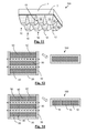
- Figures 13 and 14 show, in summary, similar arrangements of strips 30 and of additional strips 31 parallel to the longest side, with the difference that in this case there is no strip 32 arranged parallel to the shortest side between the two strips 30 located on the two shortest sides. Furthermore, it can be seen in Figure 14 that between the space created between the strips 30 and 31 there is arranged not one but three plates 50 ( Figure 13 ) separated from one another by a certain distance, resulting in the manufacture of lining plates 100 of the type shown in Figure 2 , i.e., in which the main layer 1 is formed by several individual parts.
Landscapes
- Engineering & Computer Science (AREA)
- Architecture (AREA)
- Civil Engineering (AREA)
- Structural Engineering (AREA)
- Floor Finish (AREA)
- Road Paving Structures (AREA)
Applications Claiming Priority (1)
| Application Number | Priority Date | Filing Date | Title |
|---|---|---|---|
| ES201430727A ES2551632B1 (es) | 2014-05-20 | 2014-05-20 | Placa de revestimiento multicapa para superficies de apoyo horizontales y procedimiento para su fabricación |
Publications (2)
| Publication Number | Publication Date |
|---|---|
| EP2960397A1 true EP2960397A1 (fr) | 2015-12-30 |
| EP2960397B1 EP2960397B1 (fr) | 2019-07-10 |
Family
ID=53373376
Family Applications (1)
| Application Number | Title | Priority Date | Filing Date |
|---|---|---|---|
| EP15382260.6A Active EP2960397B1 (fr) | 2014-05-20 | 2015-05-19 | Plaque de revêtement multicouche pour des surfaces de support horizontal et son procédé de fabrication |
Country Status (4)
| Country | Link |
|---|---|
| US (1) | US9593493B2 (fr) |
| EP (1) | EP2960397B1 (fr) |
| ES (2) | ES2551632B1 (fr) |
| PT (1) | PT2960397T (fr) |
Cited By (6)
| Publication number | Priority date | Publication date | Assignee | Title |
|---|---|---|---|---|
| CN105649303A (zh) * | 2016-03-08 | 2016-06-08 | 安徽韩华建材科技股份有限公司 | 一种嵌入式抗拉力地板及其制作方法 |
| WO2018130729A1 (fr) * | 2017-01-12 | 2018-07-19 | Euro Trade Flooring, S.L. | Plaque de revêtement de surfaces horizontales et verticales |
| EP3450653A1 (fr) * | 2017-09-01 | 2019-03-06 | Tarkett GDL S.A. | Kit pour la réalisation d'un revêtement de sol |
| EP3450652A1 (fr) * | 2017-09-01 | 2019-03-06 | Tarkett GDL S.A. | Kit de dalles pour la réalisation d'un revêtement de sol |
| WO2021005252A1 (fr) | 2019-07-10 | 2021-01-14 | Euro Trade Flooring, S.L. | Plaque et système de revêtement de surfaces verticales et horizontales |
| EP3947849A4 (fr) * | 2019-03-25 | 2022-12-07 | Ceraloc Innovation AB | Panneau à base de minéraux comprenant des rainures et procédé de formation de rainures |
Families Citing this family (8)
| Publication number | Priority date | Publication date | Assignee | Title |
|---|---|---|---|---|
| US10293571B2 (en) * | 2014-05-20 | 2019-05-21 | Euro Trade Flooring, S.L. | Multilayer lining plate for horizontal support |
| ES2927610T3 (es) * | 2016-03-23 | 2022-11-08 | Li & Co AG | Elemento de revestimiento de pared o suelo |
| BE1024723B1 (nl) * | 2016-11-10 | 2018-06-11 | Ivc Bvba | Vloerpaneel en werkwijze voor het vervaardigen van een vloerpaneel. |
| CA2979897C (fr) * | 2017-06-07 | 2019-01-08 | Lucida Flooring International Inc. | Panneau de plancher comportant des mecanismes de verrouillage renfermant un polymere |
| CN109306784B (zh) * | 2018-10-12 | 2023-08-11 | 浙江亚厦装饰股份有限公司 | 无机复合板结构及其生产工艺 |
| NL2022114B1 (en) | 2018-12-03 | 2020-06-30 | I4F Licensing Nv | Decorative panel, and decorative floor covering consisting of said panels |
| GB2582958C (en) | 2019-04-11 | 2022-10-26 | Altro Ltd | Ventilating synthetic floor covering |
| CN115516181A (zh) * | 2020-05-12 | 2022-12-23 | 瓦林格创新股份有限公司 | 包括机械锁定装置的基于矿物的镶板 |
Citations (3)
| Publication number | Priority date | Publication date | Assignee | Title |
|---|---|---|---|---|
| DE7438712U (de) * | 1974-11-20 | 1975-03-27 | Niederguenzl J | Fertigparkett-Element |
| DE10163435C1 (de) * | 2001-12-21 | 2003-02-06 | Johannes Schulte | Parkettdiele |
| EP2586929A1 (fr) * | 2011-10-28 | 2013-05-01 | Ulrich Windmöller Consulting GmbH | Revêtement de sol |
Family Cites Families (6)
| Publication number | Priority date | Publication date | Assignee | Title |
|---|---|---|---|---|
| BE1018728A3 (nl) * | 2009-04-22 | 2011-07-05 | Flooring Ind Ltd Sarl | Vloerpaneel. |
| CN101881076B (zh) * | 2010-06-09 | 2014-07-09 | 黄焕文 | 一种方便铺的组合式地板 |
| BE1019747A3 (nl) * | 2010-07-15 | 2012-12-04 | Flooring Ind Ltd Sarl | Bekleding, alsmede panelen en hulpstukken daarbij aangewend. |
| CN102337770A (zh) * | 2011-04-12 | 2012-02-01 | 上海亮世国际贸易有限公司 | 建筑板材及其制造方法 |
| CN202108216U (zh) * | 2011-05-13 | 2012-01-11 | 吴家敏 | 瓦型夹心采暖地板 |
| DE102012000468B4 (de) * | 2012-01-13 | 2017-08-17 | Falquon Gmbh | Bodenpaneel und Verfahren zu seiner Herstellung |
-
2014
- 2014-05-20 ES ES201430727A patent/ES2551632B1/es not_active Expired - Fee Related
- 2014-09-23 US US14/493,668 patent/US9593493B2/en active Active
-
2015
- 2015-05-19 PT PT15382260T patent/PT2960397T/pt unknown
- 2015-05-19 ES ES15382260T patent/ES2748277T3/es active Active
- 2015-05-19 EP EP15382260.6A patent/EP2960397B1/fr active Active
Patent Citations (3)
| Publication number | Priority date | Publication date | Assignee | Title |
|---|---|---|---|---|
| DE7438712U (de) * | 1974-11-20 | 1975-03-27 | Niederguenzl J | Fertigparkett-Element |
| DE10163435C1 (de) * | 2001-12-21 | 2003-02-06 | Johannes Schulte | Parkettdiele |
| EP2586929A1 (fr) * | 2011-10-28 | 2013-05-01 | Ulrich Windmöller Consulting GmbH | Revêtement de sol |
Cited By (8)
| Publication number | Priority date | Publication date | Assignee | Title |
|---|---|---|---|---|
| CN105649303A (zh) * | 2016-03-08 | 2016-06-08 | 安徽韩华建材科技股份有限公司 | 一种嵌入式抗拉力地板及其制作方法 |
| WO2018130729A1 (fr) * | 2017-01-12 | 2018-07-19 | Euro Trade Flooring, S.L. | Plaque de revêtement de surfaces horizontales et verticales |
| US11020940B2 (en) | 2017-01-12 | 2021-06-01 | Euro Trade Flooring, S.L. | Plate for covering horizontal and vertical surfaces |
| EP3450653A1 (fr) * | 2017-09-01 | 2019-03-06 | Tarkett GDL S.A. | Kit pour la réalisation d'un revêtement de sol |
| EP3450652A1 (fr) * | 2017-09-01 | 2019-03-06 | Tarkett GDL S.A. | Kit de dalles pour la réalisation d'un revêtement de sol |
| WO2019043190A1 (fr) * | 2017-09-01 | 2019-03-07 | Tarkett Gdl S.A. | Kit de carreaux pour constituer un revêtement de sol |
| EP3947849A4 (fr) * | 2019-03-25 | 2022-12-07 | Ceraloc Innovation AB | Panneau à base de minéraux comprenant des rainures et procédé de formation de rainures |
| WO2021005252A1 (fr) | 2019-07-10 | 2021-01-14 | Euro Trade Flooring, S.L. | Plaque et système de revêtement de surfaces verticales et horizontales |
Also Published As
| Publication number | Publication date |
|---|---|
| US20150337545A1 (en) | 2015-11-26 |
| ES2551632A1 (es) | 2015-11-20 |
| ES2551632B1 (es) | 2016-09-08 |
| EP2960397B1 (fr) | 2019-07-10 |
| PT2960397T (pt) | 2019-09-09 |
| ES2748277T3 (es) | 2020-03-16 |
| US9593493B2 (en) | 2017-03-14 |
Similar Documents
| Publication | Publication Date | Title |
|---|---|---|
| US9593493B2 (en) | Multilayer lining plate for horizontal support surfaces and method of manufacturing same | |
| JP4573828B2 (ja) | タイル | |
| EP1802828B1 (fr) | Element de substrat, element de carrelage modulaire, systeme de verrouillage de mecanismes et procede de carrelage | |
| US10858844B2 (en) | Building element in plate shape, in particular floor covering panel, as well as floor covering formed by using said building elements, and method for their arrangement | |
| NO20161835A1 (no) | Laminert gulvflissammenstilling og fremgangsmåte for fremstilling av en laminert gulvflissammenstilling | |
| WO2012158846A1 (fr) | Système de plancher à carreaux de luxe en vinyle | |
| US20080005988A1 (en) | Floor or wall covering | |
| EP3625408B1 (fr) | Élément de plancher pour former un revêtement de plancher et revêtement de plancher | |
| US10293571B2 (en) | Multilayer lining plate for horizontal support | |
| ITMI20101201A1 (it) | Modulo di pavimentazione radiante | |
| WO2019008347A1 (fr) | Revêtement de sol magnétique | |
| CN206467960U (zh) | 用于水平支撑面的多层衬板 | |
| WO2016192805A1 (fr) | Revêtement décoratif multi-couche pour surfaces horizontales et verticales | |
| US20170239839A1 (en) | System and method for forming prefabricated building panels | |
| EP3998154A1 (fr) | Plaque et système de revêtement de surfaces verticales et horizontales | |
| US20050028453A1 (en) | Stone laminated structure and method for its construction | |
| CN217027845U (zh) | 一种具有耐候、耐水性能的超薄干式墙地砖 | |
| CN215631343U (zh) | 一种适老居室中地面的收口结构 | |
| NL2025165B1 (en) | Tile panel, and a surface covering constructed by a multitude of neighbouring tile panels | |
| EP3927909B1 (fr) | Dispositif destiné à être disposé dans une construction de plancher | |
| KR20200013736A (ko) | 실내 바닥 마감재 및 그 마감재를 이용한 바닥 시공방법 | |
| JP2024006837A (ja) | 置き型タイル | |
| US20140162011A1 (en) | Element for Dry Joining that Provides Insulation, and Method Incorporating said Element | |
| JP3107800U (ja) | 自然石パネル外壁材 | |
| AU2005218056A1 (en) | Underlay for removable tile flooring |
Legal Events
| Date | Code | Title | Description |
|---|---|---|---|
| PUAI | Public reference made under article 153(3) epc to a published international application that has entered the european phase |
Free format text: ORIGINAL CODE: 0009012 |
|
| AK | Designated contracting states |
Kind code of ref document: A1 Designated state(s): AL AT BE BG CH CY CZ DE DK EE ES FI FR GB GR HR HU IE IS IT LI LT LU LV MC MK MT NL NO PL PT RO RS SE SI SK SM TR |
|
| AX | Request for extension of the european patent |
Extension state: BA ME |
|
| 17P | Request for examination filed |
Effective date: 20160418 |
|
| RBV | Designated contracting states (corrected) |
Designated state(s): AL AT BE BG CH CY CZ DE DK EE ES FI FR GB GR HR HU IE IS IT LI LT LU LV MC MK MT NL NO PL PT RO RS SE SI SK SM TR |
|
| STAA | Information on the status of an ep patent application or granted ep patent |
Free format text: STATUS: EXAMINATION IS IN PROGRESS |
|
| 17Q | First examination report despatched |
Effective date: 20180220 |
|
| GRAP | Despatch of communication of intention to grant a patent |
Free format text: ORIGINAL CODE: EPIDOSNIGR1 |
|
| STAA | Information on the status of an ep patent application or granted ep patent |
Free format text: STATUS: GRANT OF PATENT IS INTENDED |
|
| INTG | Intention to grant announced |
Effective date: 20190221 |
|
| GRAS | Grant fee paid |
Free format text: ORIGINAL CODE: EPIDOSNIGR3 |
|
| GRAA | (expected) grant |
Free format text: ORIGINAL CODE: 0009210 |
|
| STAA | Information on the status of an ep patent application or granted ep patent |
Free format text: STATUS: THE PATENT HAS BEEN GRANTED |
|
| AK | Designated contracting states |
Kind code of ref document: B1 Designated state(s): AL AT BE BG CH CY CZ DE DK EE ES FI FR GB GR HR HU IE IS IT LI LT LU LV MC MK MT NL NO PL PT RO RS SE SI SK SM TR |
|
| REG | Reference to a national code |
Ref country code: GB Ref legal event code: FG4D |
|
| REG | Reference to a national code |
Ref country code: CH Ref legal event code: EP Ref country code: AT Ref legal event code: REF Ref document number: 1153723 Country of ref document: AT Kind code of ref document: T Effective date: 20190715 |
|
| REG | Reference to a national code |
Ref country code: IE Ref legal event code: FG4D |
|
| REG | Reference to a national code |
Ref country code: DE Ref legal event code: R096 Ref document number: 602015033447 Country of ref document: DE |
|
| REG | Reference to a national code |
Ref country code: NL Ref legal event code: FP |
|
| REG | Reference to a national code |
Ref country code: PT Ref legal event code: SC4A Ref document number: 2960397 Country of ref document: PT Date of ref document: 20190909 Kind code of ref document: T Free format text: AVAILABILITY OF NATIONAL TRANSLATION Effective date: 20190822 |
|
| REG | Reference to a national code |
Ref country code: LT Ref legal event code: MG4D |
|
| REG | Reference to a national code |
Ref country code: AT Ref legal event code: MK05 Ref document number: 1153723 Country of ref document: AT Kind code of ref document: T Effective date: 20190710 |
|
| PG25 | Lapsed in a contracting state [announced via postgrant information from national office to epo] |
Ref country code: NO Free format text: LAPSE BECAUSE OF FAILURE TO SUBMIT A TRANSLATION OF THE DESCRIPTION OR TO PAY THE FEE WITHIN THE PRESCRIBED TIME-LIMIT Effective date: 20191010 Ref country code: SE Free format text: LAPSE BECAUSE OF FAILURE TO SUBMIT A TRANSLATION OF THE DESCRIPTION OR TO PAY THE FEE WITHIN THE PRESCRIBED TIME-LIMIT Effective date: 20190710 Ref country code: BG Free format text: LAPSE BECAUSE OF FAILURE TO SUBMIT A TRANSLATION OF THE DESCRIPTION OR TO PAY THE FEE WITHIN THE PRESCRIBED TIME-LIMIT Effective date: 20191010 Ref country code: AT Free format text: LAPSE BECAUSE OF FAILURE TO SUBMIT A TRANSLATION OF THE DESCRIPTION OR TO PAY THE FEE WITHIN THE PRESCRIBED TIME-LIMIT Effective date: 20190710 Ref country code: FI Free format text: LAPSE BECAUSE OF FAILURE TO SUBMIT A TRANSLATION OF THE DESCRIPTION OR TO PAY THE FEE WITHIN THE PRESCRIBED TIME-LIMIT Effective date: 20190710 Ref country code: HR Free format text: LAPSE BECAUSE OF FAILURE TO SUBMIT A TRANSLATION OF THE DESCRIPTION OR TO PAY THE FEE WITHIN THE PRESCRIBED TIME-LIMIT Effective date: 20190710 Ref country code: LT Free format text: LAPSE BECAUSE OF FAILURE TO SUBMIT A TRANSLATION OF THE DESCRIPTION OR TO PAY THE FEE WITHIN THE PRESCRIBED TIME-LIMIT Effective date: 20190710 |
|
| PG25 | Lapsed in a contracting state [announced via postgrant information from national office to epo] |
Ref country code: AL Free format text: LAPSE BECAUSE OF FAILURE TO SUBMIT A TRANSLATION OF THE DESCRIPTION OR TO PAY THE FEE WITHIN THE PRESCRIBED TIME-LIMIT Effective date: 20190710 Ref country code: LV Free format text: LAPSE BECAUSE OF FAILURE TO SUBMIT A TRANSLATION OF THE DESCRIPTION OR TO PAY THE FEE WITHIN THE PRESCRIBED TIME-LIMIT Effective date: 20190710 Ref country code: RS Free format text: LAPSE BECAUSE OF FAILURE TO SUBMIT A TRANSLATION OF THE DESCRIPTION OR TO PAY THE FEE WITHIN THE PRESCRIBED TIME-LIMIT Effective date: 20190710 Ref country code: IS Free format text: LAPSE BECAUSE OF FAILURE TO SUBMIT A TRANSLATION OF THE DESCRIPTION OR TO PAY THE FEE WITHIN THE PRESCRIBED TIME-LIMIT Effective date: 20191110 Ref country code: GR Free format text: LAPSE BECAUSE OF FAILURE TO SUBMIT A TRANSLATION OF THE DESCRIPTION OR TO PAY THE FEE WITHIN THE PRESCRIBED TIME-LIMIT Effective date: 20191011 |
|
| REG | Reference to a national code |
Ref country code: ES Ref legal event code: FG2A Ref document number: 2748277 Country of ref document: ES Kind code of ref document: T3 Effective date: 20200316 |
|
| PG25 | Lapsed in a contracting state [announced via postgrant information from national office to epo] |
Ref country code: TR Free format text: LAPSE BECAUSE OF FAILURE TO SUBMIT A TRANSLATION OF THE DESCRIPTION OR TO PAY THE FEE WITHIN THE PRESCRIBED TIME-LIMIT Effective date: 20190710 |
|
| PG25 | Lapsed in a contracting state [announced via postgrant information from national office to epo] |
Ref country code: EE Free format text: LAPSE BECAUSE OF FAILURE TO SUBMIT A TRANSLATION OF THE DESCRIPTION OR TO PAY THE FEE WITHIN THE PRESCRIBED TIME-LIMIT Effective date: 20190710 Ref country code: DK Free format text: LAPSE BECAUSE OF FAILURE TO SUBMIT A TRANSLATION OF THE DESCRIPTION OR TO PAY THE FEE WITHIN THE PRESCRIBED TIME-LIMIT Effective date: 20190710 Ref country code: PL Free format text: LAPSE BECAUSE OF FAILURE TO SUBMIT A TRANSLATION OF THE DESCRIPTION OR TO PAY THE FEE WITHIN THE PRESCRIBED TIME-LIMIT Effective date: 20190710 Ref country code: RO Free format text: LAPSE BECAUSE OF FAILURE TO SUBMIT A TRANSLATION OF THE DESCRIPTION OR TO PAY THE FEE WITHIN THE PRESCRIBED TIME-LIMIT Effective date: 20190710 |
|
| PG25 | Lapsed in a contracting state [announced via postgrant information from national office to epo] |
Ref country code: CZ Free format text: LAPSE BECAUSE OF FAILURE TO SUBMIT A TRANSLATION OF THE DESCRIPTION OR TO PAY THE FEE WITHIN THE PRESCRIBED TIME-LIMIT Effective date: 20190710 Ref country code: SK Free format text: LAPSE BECAUSE OF FAILURE TO SUBMIT A TRANSLATION OF THE DESCRIPTION OR TO PAY THE FEE WITHIN THE PRESCRIBED TIME-LIMIT Effective date: 20190710 Ref country code: SM Free format text: LAPSE BECAUSE OF FAILURE TO SUBMIT A TRANSLATION OF THE DESCRIPTION OR TO PAY THE FEE WITHIN THE PRESCRIBED TIME-LIMIT Effective date: 20190710 Ref country code: IS Free format text: LAPSE BECAUSE OF FAILURE TO SUBMIT A TRANSLATION OF THE DESCRIPTION OR TO PAY THE FEE WITHIN THE PRESCRIBED TIME-LIMIT Effective date: 20200224 |
|
| REG | Reference to a national code |
Ref country code: DE Ref legal event code: R097 Ref document number: 602015033447 Country of ref document: DE |
|
| PLBE | No opposition filed within time limit |
Free format text: ORIGINAL CODE: 0009261 |
|
| STAA | Information on the status of an ep patent application or granted ep patent |
Free format text: STATUS: NO OPPOSITION FILED WITHIN TIME LIMIT |
|
| PG2D | Information on lapse in contracting state deleted |
Ref country code: IS |
|
| PGFP | Annual fee paid to national office [announced via postgrant information from national office to epo] |
Ref country code: ES Payment date: 20200610 Year of fee payment: 6 |
|
| 26N | No opposition filed |
Effective date: 20200603 |
|
| PG25 | Lapsed in a contracting state [announced via postgrant information from national office to epo] |
Ref country code: SI Free format text: LAPSE BECAUSE OF FAILURE TO SUBMIT A TRANSLATION OF THE DESCRIPTION OR TO PAY THE FEE WITHIN THE PRESCRIBED TIME-LIMIT Effective date: 20190710 |
|
| REG | Reference to a national code |
Ref country code: DE Ref legal event code: R119 Ref document number: 602015033447 Country of ref document: DE |
|
| REG | Reference to a national code |
Ref country code: NL Ref legal event code: MM Effective date: 20200601 |
|
| PG25 | Lapsed in a contracting state [announced via postgrant information from national office to epo] |
Ref country code: CH Free format text: LAPSE BECAUSE OF NON-PAYMENT OF DUE FEES Effective date: 20200531 Ref country code: MC Free format text: LAPSE BECAUSE OF FAILURE TO SUBMIT A TRANSLATION OF THE DESCRIPTION OR TO PAY THE FEE WITHIN THE PRESCRIBED TIME-LIMIT Effective date: 20190710 Ref country code: LI Free format text: LAPSE BECAUSE OF NON-PAYMENT OF DUE FEES Effective date: 20200531 |
|
| PG25 | Lapsed in a contracting state [announced via postgrant information from national office to epo] |
Ref country code: NL Free format text: LAPSE BECAUSE OF NON-PAYMENT OF DUE FEES Effective date: 20200601 |
|
| REG | Reference to a national code |
Ref country code: BE Ref legal event code: MM Effective date: 20200531 |
|
| GBPC | Gb: european patent ceased through non-payment of renewal fee |
Effective date: 20200519 |
|
| PG25 | Lapsed in a contracting state [announced via postgrant information from national office to epo] |
Ref country code: LU Free format text: LAPSE BECAUSE OF NON-PAYMENT OF DUE FEES Effective date: 20200519 |
|
| PG25 | Lapsed in a contracting state [announced via postgrant information from national office to epo] |
Ref country code: PT Free format text: LAPSE BECAUSE OF NON-PAYMENT OF DUE FEES Effective date: 20210316 Ref country code: FR Free format text: LAPSE BECAUSE OF NON-PAYMENT OF DUE FEES Effective date: 20200531 Ref country code: IE Free format text: LAPSE BECAUSE OF NON-PAYMENT OF DUE FEES Effective date: 20200519 Ref country code: GB Free format text: LAPSE BECAUSE OF NON-PAYMENT OF DUE FEES Effective date: 20200519 |
|
| PG25 | Lapsed in a contracting state [announced via postgrant information from national office to epo] |
Ref country code: DE Free format text: LAPSE BECAUSE OF NON-PAYMENT OF DUE FEES Effective date: 20201201 Ref country code: BE Free format text: LAPSE BECAUSE OF NON-PAYMENT OF DUE FEES Effective date: 20200531 |
|
| PG25 | Lapsed in a contracting state [announced via postgrant information from national office to epo] |
Ref country code: IT Free format text: LAPSE BECAUSE OF NON-PAYMENT OF DUE FEES Effective date: 20200519 |
|
| PG25 | Lapsed in a contracting state [announced via postgrant information from national office to epo] |
Ref country code: MT Free format text: LAPSE BECAUSE OF FAILURE TO SUBMIT A TRANSLATION OF THE DESCRIPTION OR TO PAY THE FEE WITHIN THE PRESCRIBED TIME-LIMIT Effective date: 20190710 Ref country code: CY Free format text: LAPSE BECAUSE OF FAILURE TO SUBMIT A TRANSLATION OF THE DESCRIPTION OR TO PAY THE FEE WITHIN THE PRESCRIBED TIME-LIMIT Effective date: 20190710 |
|
| PG25 | Lapsed in a contracting state [announced via postgrant information from national office to epo] |
Ref country code: MK Free format text: LAPSE BECAUSE OF FAILURE TO SUBMIT A TRANSLATION OF THE DESCRIPTION OR TO PAY THE FEE WITHIN THE PRESCRIBED TIME-LIMIT Effective date: 20190710 |
|
| REG | Reference to a national code |
Ref country code: ES Ref legal event code: FD2A Effective date: 20220801 |
|
| PG25 | Lapsed in a contracting state [announced via postgrant information from national office to epo] |
Ref country code: ES Free format text: LAPSE BECAUSE OF NON-PAYMENT OF DUE FEES Effective date: 20210520 |