EP2959766A1 - Moissonneuse et son procédé de fonctionnement - Google Patents
Moissonneuse et son procédé de fonctionnement Download PDFInfo
- Publication number
- EP2959766A1 EP2959766A1 EP15162315.4A EP15162315A EP2959766A1 EP 2959766 A1 EP2959766 A1 EP 2959766A1 EP 15162315 A EP15162315 A EP 15162315A EP 2959766 A1 EP2959766 A1 EP 2959766A1
- Authority
- EP
- European Patent Office
- Prior art keywords
- rotation
- discharge chute
- harvester
- harvesting machine
- curvature
- Prior art date
- Legal status (The legal status is an assumption and is not a legal conclusion. Google has not performed a legal analysis and makes no representation as to the accuracy of the status listed.)
- Granted
Links
Images

Classifications
-
- A—HUMAN NECESSITIES
- A01—AGRICULTURE; FORESTRY; ANIMAL HUSBANDRY; HUNTING; TRAPPING; FISHING
- A01D—HARVESTING; MOWING
- A01D43/00—Mowers combined with apparatus performing additional operations while mowing
- A01D43/08—Mowers combined with apparatus performing additional operations while mowing with means for cutting up the mown crop, e.g. forage harvesters
- A01D43/086—Mowers combined with apparatus performing additional operations while mowing with means for cutting up the mown crop, e.g. forage harvesters and means for collecting, gathering or loading mown material
- A01D43/087—Mowers combined with apparatus performing additional operations while mowing with means for cutting up the mown crop, e.g. forage harvesters and means for collecting, gathering or loading mown material with controllable discharge spout
Definitions
- the invention relates to a trained according to the preamble of claim 1 in particular self-propelled harvester, such as a forage harvester or a combine harvester, and an operating method for such a harvester.
- a harvester of the type mentioned is eg off EP 2 020 176 B1 known.
- This harvester has an elongated spout which is mounted with a longitudinal end thereof on an upper surface of the harvester such that the spout is movably supported at one longitudinal end about a vertical axis of rotation and about a horizontal axis.
- the spout can be aligned to achieve a transport position for road travel by rotating about the vertical axis of rotation so that the spout extends its length in a front-rear direction of the harvester.
- the one longitudinal end of the ejection elbow is mounted via a hinge on the top of the harvester so that the discharge elbow is pivotally mounted about a horizontal pivot axis extending transversely to a longitudinal direction of the discharge elbow.
- the chute to achieve the transport position for driving on the road by pivoting about the horizontal pivot axis can be lowered so that it does not protrude above a cab of the harvester out.
- the extent of a possible height reduction of the discharge elbow u.a. depending on its curvature and on a length of the harvester.
- the invention has for its object to provide a trained according to the preamble of claim 1 harvester, the spout is alignable with fewer restrictions to achieve a transport position.
- the invention is also based on the object to provide an operating method for such a harvester to spend the spout from an operating position of its in its transport position.
- a particular self-propelled harvester such as a forage harvester or combine harvester, having an elongated spout mounted to a top end of the harvester with a longitudinal end thereof such that the spout at one longitudinal end is pivotal about a vertical axis of rotation a horizontal axis is movably mounted.
- the spout is alignable by rotation about the vertical axis of rotation so that the spout extends longitudinally in a front-rear direction of the harvester.
- the harvesting machine is characterized in that one longitudinal end of the discharge chute is mounted on the upper side of the harvester such that the discharge chute is rotatably mounted about a horizontal axis of rotation extending in a longitudinal direction of the chute.
- the horizontal axis of rotation also extends in the front-rear direction of the harvester in the front-rear direction of the harvester extending in the front-rear direction of the harvester.
- the chute By rotating the chute around the horizontal axis of rotation, it can be aligned without limitation by the length of the harvester to achieve a transport position.
- the spout when the spout has a curvature, according to one embodiment of the invention, the spout is rotatable about the horizontal axis of rotation between an operating position in which an inner radius of curvature of the spout is vertically downwardly and an inoperative position in which the inner radius of curvature of the spout Spout turned 90 degrees in the horizontal direction.
- the discharge chute can be simply turned 90 degrees about the horizontal axis of rotation extending in the longitudinal direction of the chute to its inoperative position in which the curve extends in the width direction of the harvester.
- the extent of a possible drop in height of the discharge chute is no longer dependent on its curvature and / or the length of the harvester.
- the configuration of the discharge chute, in particular its curvature and thus its Ausschurfparabel for the crop no longer subject to restrictions on compliance with a total height dimension of the harvester and can be optimized free harvest material flow and energy efficiency.
- the harvesting machine may comprise a turntable to which the one longitudinal end of the discharge chute is connected, the turntable being arranged at the top of the harvesting machine so as to provide the vertical axis of rotation for the discharge chute.
- the turntable is arranged to provide, in addition to the vertical axis of rotation, also the horizontal axis of rotation for the discharge chute.
- the discharge elbow may have a manifold foot which is mounted directly on the turntable, so that the elbow foot around the provided by the turntable vertical axis of rotation is rotatable, and in which a hinge is integrated, which provides the horizontal axis of rotation for the discharge chute.
- the spout has an elongate first portion which has a curvature and which is rotatably mounted on the harvester about the vertical axis of rotation and about the horizontal axis of rotation, and an elongated second portion which is pivotable about a pivot axis on a harvester the harvesting machine facing away from the longitudinal end of the first portion is mounted so that the second portion between an unfolded position in which the second portion extends as length continuation of the first portion, and a retracted position is pivotable, in which the second portion alongside alongside the first portion is arranged.
- the pivot axis is aligned so that the second portion for realizing the folded position on the curvature of the first portion is pivotable.
- the width of the harvester can be used to stow the second portion.
- the pivot axis is arranged on the side of an inner radius of curvature of the first portion, so that the second portion for realizing the retracted position in the Inner radius of the curvature of the first portion is pivotable.
- the use of the inner radius of the curvature of the first portion for stowing the second portion is particularly space-saving.
- the harvester has such a height dimension from a road contact point thereof to the upper side, and the discharge chute is configured in its curvature and length such that an overall height dimension of the harvester defined by the chute in its operating position is greater than 4 meters ,
- the method of operation comprises at least the steps of: rotating the discharge chute by a certain amount about the vertical axis of rotation so that the discharge chute extends longitudinally in the front-rear direction of the harvester; and rotating the discharge chute 90 degrees about the horizontal axis of rotation so that the inner radius of the bend of the discharge chute is horizontal.
- the harvesting machine is designed by way of example as a self-propelled forage harvester.
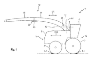
- FIG. 1 shows the harvester 1 in a schematic side view.
- a machine housing 2 of the harvester 1 includes a motor (not shown) for driving wheels 3 and a header mounted on a front side 1a of the harvester 1 (not shown).
- Crop material picked up from the ground by means of the harvesting attachment is comminuted (not shown) in a chopper drum (not shown) arranged in the interior of the machine housing 2 and discharged into a discharge chute (not shown) ascending behind a driver's cab 4.
- a Nachbe deviser also arranged on the discharge chute in the interior of the machine housing 2 hurls the chopped crop through an elongated chute 10, which gives the shredded crop for further transport, for example on a bed of a transport trailer (not shown).
- the discharge chute 10 is mounted with a longitudinal end thereof at the top of the machine housing 2 of the harvester 1 such that the discharge chute 10 is rotatably supported at one longitudinal end about a vertical axis of rotation A1 and about a horizontal axis of rotation A2 extending in a longitudinal direction LR of the chute 10 ,
- the spout 10 has an elongated first portion 11 which has a curvature and which is rotatably mounted about the vertical axis of rotation A1 and about the horizontal axis of rotation A2 on the top of the machine housing 2 of the harvester 1.
- the harvester 1 has a turntable 5, with which the one of the first portion 11 formed one longitudinal end of the discharge chute 10 is connected.
- the turntable 5 is arranged at the top of the machine housing 2 of the harvester 1 so that it provides the vertical axis of rotation A1 for the discharge chute 10.
- the spout 10 has a Krümmerfuß 12, which is mounted directly to the turntable 5, so that the Krümmerfuß 12 is rotatable about the provided by the turntable 5 vertical axis of rotation A1, and in which a pivot joint 13 is integrated, which is the horizontal axis of rotation A2 for the spout 10 provides. That the Krümmerfuß 12 facing one longitudinal end of the first portion 11 is in turn mounted directly on the pivot 13 of the manifold base 12.
- the discharge chute 10 also has an elongate second section 15, which is pivotally mounted on a longitudinal end of the first section 11 facing away from the turntable 5 of the harvester 1 via a pivot joint 20.
- the pivot joint 20 provides a pivot axis A3, so that the second portion 15 about the pivot axis A3 between a in Fig. 1 shown unfolded position in which the second portion 15 extends as a length continuation of the first portion 11, and a in Fig. 2 shown folded position is pivotable, in which the second portion 15 is arranged alongside next to the first portion 11.
- the discharge elbow 10 in its unfolded position by about the vertical axis of rotation A1 turning the first portion 11 relative to the harvester 1 between the in Fig. 1 shown position in which the chute 10 extends to achieve its transport position along its length in a front-rear direction FHR of the harvester 1 on a rear side 1 b of the harvester 1 addition, and a working position is displaceable, in which the discharge chute 10 protrudes laterally from the latter, for example transversely to the front-rear direction FHR of the harvester 1.
- the horizontal axis of rotation A2 also extends in the front-rear direction FHR of the harvester 1 extending discharge chute 10 in the front-rear direction FHR of the harvester 1 in the front-rear direction FHR.
- the pivot axis A3 of the pivot joint 20 is aligned so that the second portion 15 for realizing the folded position on the curvature of the first portion 11 is pivotable. More specifically, the pivot joint 20 is arranged so that the pivot axis A3 is located on an inner radius side of the curvature of the first section 11, so that the second section 15 for realizing the collapsed position as in FIG Fig. 2 shown in the inner radius of the curvature of the first portion 11 is pivotable.
- the discharge chute 10 Due to the curvature of the first section 11 and possibly a curvature of the second section 15, the discharge chute 10 in its entirety has a curvature.
- the horizontal axis of rotation A2 of the discharge chute 10 between an in Fig. 1 shown operating position in which an inner radius of the curvature of the discharge chute 10 points vertically downwards, and one in Fig. 2 shown inoperative position rotatably movable, in which the inner radius of the curvature of the discharge elbow has turned by 90 degrees in the horizontal.
- the pivot axis A3 of the pivot joint 20 in the operating position extends horizontally and transversely to the front-rear direction FHR and in the inoperative position vertically.
- the harvester 1 has such a height dimension from a road contact point 3.1 defined by its wheels 3 to the top of the machine housing 2, and the discharge chute 10 is configured with respect to its curvature and length such that the discharge chute 10 has an overall height dimension the harvester 1 of greater than 4 meters is defined when the spout 10 is in the operating position and the deployed position. Since such an overall height dimension of the harvester 1 for road driving the harvester 1 is inadmissible, the spout 10 for road travel in the in Fig. 2 shown transport position spent.
- the position shown is first rotated by a certain amount (depending on the rotational position of the discharge chute 10 with respect to the vertical axis of rotation A1) about the vertical axis of rotation A1, so that the discharge chute 10 extends longitudinally in the front-rear direction FHR of the harvester 1 extends as in Fig. 1 shown. Thereafter, the discharge chute 10 is rotated 90 degrees about the horizontal axis of rotation A2 in the inoperative position, so that the inner radius of the curvature of the discharge chute 10 points in the horizontal.
- the second portion 15 of the discharge elbow 10 is pivoted about the now vertically extending pivot axis A3 by about 180 degrees to the first portion 11 of the discharge chute 10 back into the retracted position, so that both sections 11, 15 of the discharge chute 10 in approximately parallel to Front-rear direction FHR of the harvester 1 arranged side by side alongside each other extend rearward or beyond the rear side 1 b of the harvester 1, as in Fig. 2 shown.
- the transport position of the discharge chute 10 is realized.
- the discharge chute 10 is in the transport position on the upper side of the machine housing 2, so that it is supported vertically.
- the pivot joint 20 is preferably designed so that the second portion 15 of the discharge chute 10 are easily disassembled and not shown by another second portion (eg other length and / or other curvature) can be replaced.
- another second portion eg other length and / or other curvature
- the pivot joint 20 is preferably designed so that the second portion 15 of the discharge chute 10 are easily disassembled and not shown by another second portion (eg other length and / or other curvature) can be replaced.
- another second portion eg other length and / or other curvature
- the turntable 5 can also be arranged so that it also provides the horizontal axis of rotation A2 for the discharge chute 10 in addition to the vertical axis of rotation A1.
- the Krümmerfuß 12 can be omitted with the hinge 13 and the first portion 11 is mounted directly to a built-in turntable 5 pivot to provide the horizontal axis of rotation A2.
Landscapes
- Life Sciences & Earth Sciences (AREA)
- Environmental Sciences (AREA)
- Harvesting Machines For Root Crops (AREA)
Applications Claiming Priority (1)
| Application Number | Priority Date | Filing Date | Title |
|---|---|---|---|
| DE102014109064.0A DE102014109064A1 (de) | 2014-06-27 | 2014-06-27 | Erntemaschine und Betriebsverfahren dafür |
Publications (2)
| Publication Number | Publication Date |
|---|---|
| EP2959766A1 true EP2959766A1 (fr) | 2015-12-30 |
| EP2959766B1 EP2959766B1 (fr) | 2019-06-12 |
Family
ID=52824068
Family Applications (1)
| Application Number | Title | Priority Date | Filing Date |
|---|---|---|---|
| EP15162315.4A Active EP2959766B1 (fr) | 2014-06-27 | 2015-04-02 | Moissonneuse et son procédé de fonctionnement |
Country Status (2)
| Country | Link |
|---|---|
| EP (1) | EP2959766B1 (fr) |
| DE (1) | DE102014109064A1 (fr) |
Cited By (3)
| Publication number | Priority date | Publication date | Assignee | Title |
|---|---|---|---|---|
| CN109480306A (zh) * | 2018-12-18 | 2019-03-19 | 浙江舟富食品有限公司 | 一种食材清洗装置 |
| BE1026568B1 (de) * | 2018-09-07 | 2020-08-20 | Deere & Co | Selbstfahrende erntemaschine mit einer überladeeinrichtung |
| CN114041352A (zh) * | 2021-11-11 | 2022-02-15 | 河北英虎农业机械股份有限公司 | 一种二次抛送机构及茎穗兼收型玉米收获机 |
Citations (5)
| Publication number | Priority date | Publication date | Assignee | Title |
|---|---|---|---|---|
| US2720424A (en) * | 1946-06-29 | 1955-10-11 | Case Co J I | Delivery pipe for harvester |
| DE19802199A1 (de) * | 1998-01-22 | 1999-07-29 | Ernst Dipl Ing Schumacher | Entleervorrichtung für einen Behälter |
| US20060019732A1 (en) * | 2004-07-20 | 2006-01-26 | Marcus Hettiger | Discharge arrangement of an agricultural harvesting machine |
| EP1894463A1 (fr) * | 2006-08-28 | 2008-03-05 | CLAAS Selbstfahrende Erntemaschinen GmbH | Moissonneuse agricole dotée d'un dispositif de surcharge |
| US20090113868A1 (en) * | 2007-08-03 | 2009-05-07 | Andreas Haffert | Harvester having a transfer means |
-
2014
- 2014-06-27 DE DE102014109064.0A patent/DE102014109064A1/de not_active Withdrawn
-
2015
- 2015-04-02 EP EP15162315.4A patent/EP2959766B1/fr active Active
Patent Citations (6)
| Publication number | Priority date | Publication date | Assignee | Title |
|---|---|---|---|---|
| US2720424A (en) * | 1946-06-29 | 1955-10-11 | Case Co J I | Delivery pipe for harvester |
| DE19802199A1 (de) * | 1998-01-22 | 1999-07-29 | Ernst Dipl Ing Schumacher | Entleervorrichtung für einen Behälter |
| US20060019732A1 (en) * | 2004-07-20 | 2006-01-26 | Marcus Hettiger | Discharge arrangement of an agricultural harvesting machine |
| EP1894463A1 (fr) * | 2006-08-28 | 2008-03-05 | CLAAS Selbstfahrende Erntemaschinen GmbH | Moissonneuse agricole dotée d'un dispositif de surcharge |
| US20090113868A1 (en) * | 2007-08-03 | 2009-05-07 | Andreas Haffert | Harvester having a transfer means |
| EP2020176B1 (fr) | 2007-08-03 | 2012-10-24 | CLAAS Selbstfahrende Erntemaschinen GmbH | Moissonneuse dotée d'un dispositif de transbordement |
Cited By (4)
| Publication number | Priority date | Publication date | Assignee | Title |
|---|---|---|---|---|
| BE1026568B1 (de) * | 2018-09-07 | 2020-08-20 | Deere & Co | Selbstfahrende erntemaschine mit einer überladeeinrichtung |
| CN109480306A (zh) * | 2018-12-18 | 2019-03-19 | 浙江舟富食品有限公司 | 一种食材清洗装置 |
| CN109480306B (zh) * | 2018-12-18 | 2024-02-20 | 浙江舟富食品有限公司 | 一种食材清洗装置 |
| CN114041352A (zh) * | 2021-11-11 | 2022-02-15 | 河北英虎农业机械股份有限公司 | 一种二次抛送机构及茎穗兼收型玉米收获机 |
Also Published As
| Publication number | Publication date |
|---|---|
| DE102014109064A1 (de) | 2015-12-31 |
| EP2959766B1 (fr) | 2019-06-12 |
Similar Documents
| Publication | Publication Date | Title |
|---|---|---|
| DE19931684C1 (de) | Gerätekombination zum Ernten von landwirtschaftlichem Halmgut | |
| DE102004022534B4 (de) | Erntemaschine zum Ernten von stängelartigem Erntegut wie Mais oder dergleichen | |
| EP1709858A1 (fr) | Tête de récolte pour machines agricoles | |
| DE102013100057A1 (de) | Dreschvorrichtung | |
| EP2979529B1 (fr) | Machine agricole repliable | |
| EP2959766B1 (fr) | Moissonneuse et son procédé de fonctionnement | |
| EP2366272B1 (fr) | Accessoire de récolte mobile entre une position de fonctionnement et une position de transport | |
| EP1894462B1 (fr) | Convoyeur agricole | |
| DE102006061010B4 (de) | Erntemaschine | |
| EP1588601A1 (fr) | Machine de récolte avec un dispositif de décharge | |
| EP1779715B1 (fr) | Faucheuse avec un dispositif d'andainage. | |
| DE202005007424U1 (de) | Mähbalken für Scheibenmähwerke | |
| EP3092890A1 (fr) | Barre de coupe de moissonneuse | |
| EP2011383B1 (fr) | Moissonneuse dotée d'un dispositif de coupe | |
| DE3329276A1 (de) | Futtererntemaschine mit seitlicher foerderung | |
| EP3556199B1 (fr) | Machine de fenaison agricole | |
| EP2848112B1 (fr) | Moissonneuse-batteuse équipée d'un dispositif de séparation | |
| DE112004001079T5 (de) | Mähdrescher mit einem Verteiler für Pflanzenreste | |
| DE102011113121A1 (de) | Kombinierbarer Sternradschwader | |
| EP2526758B1 (fr) | Faucheuse | |
| EP3143863A1 (fr) | Dispositif de protection de bec cueilleur d'une moissonneuse et moissonneuse comprenant un tel dispositif de protection | |
| DE102006047530A1 (de) | Erntegerät mit teleskopierbarer Fördereinrichtung | |
| EP2735220B1 (fr) | Tête de récolte mobile entre une position de fonctionnement et une position de transport | |
| DE102004058461A1 (de) | Heuwerbungsmaschine | |
| DE102007053568A1 (de) | Erntemaschine |
Legal Events
| Date | Code | Title | Description |
|---|---|---|---|
| PUAI | Public reference made under article 153(3) epc to a published international application that has entered the european phase |
Free format text: ORIGINAL CODE: 0009012 |
|
| AK | Designated contracting states |
Kind code of ref document: A1 Designated state(s): AL AT BE BG CH CY CZ DE DK EE ES FI FR GB GR HR HU IE IS IT LI LT LU LV MC MK MT NL NO PL PT RO RS SE SI SK SM TR |
|
| AX | Request for extension of the european patent |
Extension state: BA ME |
|
| 17P | Request for examination filed |
Effective date: 20160630 |
|
| RBV | Designated contracting states (corrected) |
Designated state(s): AL AT BE BG CH CY CZ DE DK EE ES FI FR GB GR HR HU IE IS IT LI LT LU LV MC MK MT NL NO PL PT RO RS SE SI SK SM TR |
|
| RAP1 | Party data changed (applicant data changed or rights of an application transferred) |
Owner name: CLAAS SELBSTFAHRENDE ERNTEMASCHINEN GMBH |
|
| RAP1 | Party data changed (applicant data changed or rights of an application transferred) |
Owner name: CLAAS SAULGAU GMBH |
|
| GRAP | Despatch of communication of intention to grant a patent |
Free format text: ORIGINAL CODE: EPIDOSNIGR1 |
|
| STAA | Information on the status of an ep patent application or granted ep patent |
Free format text: STATUS: GRANT OF PATENT IS INTENDED |
|
| INTG | Intention to grant announced |
Effective date: 20190219 |
|
| GRAS | Grant fee paid |
Free format text: ORIGINAL CODE: EPIDOSNIGR3 |
|
| GRAA | (expected) grant |
Free format text: ORIGINAL CODE: 0009210 |
|
| STAA | Information on the status of an ep patent application or granted ep patent |
Free format text: STATUS: THE PATENT HAS BEEN GRANTED |
|
| AK | Designated contracting states |
Kind code of ref document: B1 Designated state(s): AL AT BE BG CH CY CZ DE DK EE ES FI FR GB GR HR HU IE IS IT LI LT LU LV MC MK MT NL NO PL PT RO RS SE SI SK SM TR |
|
| REG | Reference to a national code |
Ref country code: GB Ref legal event code: FG4D Free format text: NOT ENGLISH |
|
| REG | Reference to a national code |
Ref country code: CH Ref legal event code: EP |
|
| REG | Reference to a national code |
Ref country code: AT Ref legal event code: REF Ref document number: 1141331 Country of ref document: AT Kind code of ref document: T Effective date: 20190615 |
|
| REG | Reference to a national code |
Ref country code: DE Ref legal event code: R096 Ref document number: 502015009275 Country of ref document: DE |
|
| REG | Reference to a national code |
Ref country code: IE Ref legal event code: FG4D Free format text: LANGUAGE OF EP DOCUMENT: GERMAN |
|
| REG | Reference to a national code |
Ref country code: NL Ref legal event code: MP Effective date: 20190612 |
|
| REG | Reference to a national code |
Ref country code: LT Ref legal event code: MG4D |
|
| PG25 | Lapsed in a contracting state [announced via postgrant information from national office to epo] |
Ref country code: SE Free format text: LAPSE BECAUSE OF FAILURE TO SUBMIT A TRANSLATION OF THE DESCRIPTION OR TO PAY THE FEE WITHIN THE PRESCRIBED TIME-LIMIT Effective date: 20190612 Ref country code: HR Free format text: LAPSE BECAUSE OF FAILURE TO SUBMIT A TRANSLATION OF THE DESCRIPTION OR TO PAY THE FEE WITHIN THE PRESCRIBED TIME-LIMIT Effective date: 20190612 Ref country code: AL Free format text: LAPSE BECAUSE OF FAILURE TO SUBMIT A TRANSLATION OF THE DESCRIPTION OR TO PAY THE FEE WITHIN THE PRESCRIBED TIME-LIMIT Effective date: 20190612 Ref country code: NO Free format text: LAPSE BECAUSE OF FAILURE TO SUBMIT A TRANSLATION OF THE DESCRIPTION OR TO PAY THE FEE WITHIN THE PRESCRIBED TIME-LIMIT Effective date: 20190912 Ref country code: FI Free format text: LAPSE BECAUSE OF FAILURE TO SUBMIT A TRANSLATION OF THE DESCRIPTION OR TO PAY THE FEE WITHIN THE PRESCRIBED TIME-LIMIT Effective date: 20190612 Ref country code: LT Free format text: LAPSE BECAUSE OF FAILURE TO SUBMIT A TRANSLATION OF THE DESCRIPTION OR TO PAY THE FEE WITHIN THE PRESCRIBED TIME-LIMIT Effective date: 20190612 |
|
| PG25 | Lapsed in a contracting state [announced via postgrant information from national office to epo] |
Ref country code: BG Free format text: LAPSE BECAUSE OF FAILURE TO SUBMIT A TRANSLATION OF THE DESCRIPTION OR TO PAY THE FEE WITHIN THE PRESCRIBED TIME-LIMIT Effective date: 20190912 Ref country code: RS Free format text: LAPSE BECAUSE OF FAILURE TO SUBMIT A TRANSLATION OF THE DESCRIPTION OR TO PAY THE FEE WITHIN THE PRESCRIBED TIME-LIMIT Effective date: 20190612 Ref country code: LV Free format text: LAPSE BECAUSE OF FAILURE TO SUBMIT A TRANSLATION OF THE DESCRIPTION OR TO PAY THE FEE WITHIN THE PRESCRIBED TIME-LIMIT Effective date: 20190612 Ref country code: GR Free format text: LAPSE BECAUSE OF FAILURE TO SUBMIT A TRANSLATION OF THE DESCRIPTION OR TO PAY THE FEE WITHIN THE PRESCRIBED TIME-LIMIT Effective date: 20190913 |
|
| PG25 | Lapsed in a contracting state [announced via postgrant information from national office to epo] |
Ref country code: NL Free format text: LAPSE BECAUSE OF FAILURE TO SUBMIT A TRANSLATION OF THE DESCRIPTION OR TO PAY THE FEE WITHIN THE PRESCRIBED TIME-LIMIT Effective date: 20190612 Ref country code: EE Free format text: LAPSE BECAUSE OF FAILURE TO SUBMIT A TRANSLATION OF THE DESCRIPTION OR TO PAY THE FEE WITHIN THE PRESCRIBED TIME-LIMIT Effective date: 20190612 Ref country code: CZ Free format text: LAPSE BECAUSE OF FAILURE TO SUBMIT A TRANSLATION OF THE DESCRIPTION OR TO PAY THE FEE WITHIN THE PRESCRIBED TIME-LIMIT Effective date: 20190612 Ref country code: SK Free format text: LAPSE BECAUSE OF FAILURE TO SUBMIT A TRANSLATION OF THE DESCRIPTION OR TO PAY THE FEE WITHIN THE PRESCRIBED TIME-LIMIT Effective date: 20190612 Ref country code: RO Free format text: LAPSE BECAUSE OF FAILURE TO SUBMIT A TRANSLATION OF THE DESCRIPTION OR TO PAY THE FEE WITHIN THE PRESCRIBED TIME-LIMIT Effective date: 20190612 Ref country code: PT Free format text: LAPSE BECAUSE OF FAILURE TO SUBMIT A TRANSLATION OF THE DESCRIPTION OR TO PAY THE FEE WITHIN THE PRESCRIBED TIME-LIMIT Effective date: 20191014 |
|
| PG25 | Lapsed in a contracting state [announced via postgrant information from national office to epo] |
Ref country code: SM Free format text: LAPSE BECAUSE OF FAILURE TO SUBMIT A TRANSLATION OF THE DESCRIPTION OR TO PAY THE FEE WITHIN THE PRESCRIBED TIME-LIMIT Effective date: 20190612 Ref country code: IS Free format text: LAPSE BECAUSE OF FAILURE TO SUBMIT A TRANSLATION OF THE DESCRIPTION OR TO PAY THE FEE WITHIN THE PRESCRIBED TIME-LIMIT Effective date: 20191012 Ref country code: IT Free format text: LAPSE BECAUSE OF FAILURE TO SUBMIT A TRANSLATION OF THE DESCRIPTION OR TO PAY THE FEE WITHIN THE PRESCRIBED TIME-LIMIT Effective date: 20190612 Ref country code: ES Free format text: LAPSE BECAUSE OF FAILURE TO SUBMIT A TRANSLATION OF THE DESCRIPTION OR TO PAY THE FEE WITHIN THE PRESCRIBED TIME-LIMIT Effective date: 20190612 |
|
| REG | Reference to a national code |
Ref country code: DE Ref legal event code: R097 Ref document number: 502015009275 Country of ref document: DE |
|
| PG25 | Lapsed in a contracting state [announced via postgrant information from national office to epo] |
Ref country code: TR Free format text: LAPSE BECAUSE OF FAILURE TO SUBMIT A TRANSLATION OF THE DESCRIPTION OR TO PAY THE FEE WITHIN THE PRESCRIBED TIME-LIMIT Effective date: 20190612 |
|
| PLBE | No opposition filed within time limit |
Free format text: ORIGINAL CODE: 0009261 |
|
| STAA | Information on the status of an ep patent application or granted ep patent |
Free format text: STATUS: NO OPPOSITION FILED WITHIN TIME LIMIT |
|
| PG25 | Lapsed in a contracting state [announced via postgrant information from national office to epo] |
Ref country code: DK Free format text: LAPSE BECAUSE OF FAILURE TO SUBMIT A TRANSLATION OF THE DESCRIPTION OR TO PAY THE FEE WITHIN THE PRESCRIBED TIME-LIMIT Effective date: 20190612 Ref country code: PL Free format text: LAPSE BECAUSE OF FAILURE TO SUBMIT A TRANSLATION OF THE DESCRIPTION OR TO PAY THE FEE WITHIN THE PRESCRIBED TIME-LIMIT Effective date: 20190612 |
|
| 26N | No opposition filed |
Effective date: 20200313 |
|
| PG25 | Lapsed in a contracting state [announced via postgrant information from national office to epo] |
Ref country code: IS Free format text: LAPSE BECAUSE OF FAILURE TO SUBMIT A TRANSLATION OF THE DESCRIPTION OR TO PAY THE FEE WITHIN THE PRESCRIBED TIME-LIMIT Effective date: 20200224 Ref country code: SI Free format text: LAPSE BECAUSE OF FAILURE TO SUBMIT A TRANSLATION OF THE DESCRIPTION OR TO PAY THE FEE WITHIN THE PRESCRIBED TIME-LIMIT Effective date: 20190612 |
|
| PG2D | Information on lapse in contracting state deleted |
Ref country code: IS |
|
| PG25 | Lapsed in a contracting state [announced via postgrant information from national office to epo] |
Ref country code: MC Free format text: LAPSE BECAUSE OF FAILURE TO SUBMIT A TRANSLATION OF THE DESCRIPTION OR TO PAY THE FEE WITHIN THE PRESCRIBED TIME-LIMIT Effective date: 20190612 |
|
| REG | Reference to a national code |
Ref country code: CH Ref legal event code: PL |
|
| PG25 | Lapsed in a contracting state [announced via postgrant information from national office to epo] |
Ref country code: CH Free format text: LAPSE BECAUSE OF NON-PAYMENT OF DUE FEES Effective date: 20200430 Ref country code: LI Free format text: LAPSE BECAUSE OF NON-PAYMENT OF DUE FEES Effective date: 20200430 Ref country code: FR Free format text: LAPSE BECAUSE OF NON-PAYMENT OF DUE FEES Effective date: 20200430 Ref country code: LU Free format text: LAPSE BECAUSE OF NON-PAYMENT OF DUE FEES Effective date: 20200402 |
|
| GBPC | Gb: european patent ceased through non-payment of renewal fee |
Effective date: 20200402 |
|
| PG25 | Lapsed in a contracting state [announced via postgrant information from national office to epo] |
Ref country code: IE Free format text: LAPSE BECAUSE OF NON-PAYMENT OF DUE FEES Effective date: 20200402 Ref country code: GB Free format text: LAPSE BECAUSE OF NON-PAYMENT OF DUE FEES Effective date: 20200402 |
|
| REG | Reference to a national code |
Ref country code: AT Ref legal event code: MM01 Ref document number: 1141331 Country of ref document: AT Kind code of ref document: T Effective date: 20200402 |
|
| PG25 | Lapsed in a contracting state [announced via postgrant information from national office to epo] |
Ref country code: AT Free format text: LAPSE BECAUSE OF NON-PAYMENT OF DUE FEES Effective date: 20200402 |
|
| PG25 | Lapsed in a contracting state [announced via postgrant information from national office to epo] |
Ref country code: MT Free format text: LAPSE BECAUSE OF FAILURE TO SUBMIT A TRANSLATION OF THE DESCRIPTION OR TO PAY THE FEE WITHIN THE PRESCRIBED TIME-LIMIT Effective date: 20190612 Ref country code: CY Free format text: LAPSE BECAUSE OF FAILURE TO SUBMIT A TRANSLATION OF THE DESCRIPTION OR TO PAY THE FEE WITHIN THE PRESCRIBED TIME-LIMIT Effective date: 20190612 |
|
| PG25 | Lapsed in a contracting state [announced via postgrant information from national office to epo] |
Ref country code: MK Free format text: LAPSE BECAUSE OF FAILURE TO SUBMIT A TRANSLATION OF THE DESCRIPTION OR TO PAY THE FEE WITHIN THE PRESCRIBED TIME-LIMIT Effective date: 20190612 |
|
| P01 | Opt-out of the competence of the unified patent court (upc) registered |
Effective date: 20230509 |
|
| PGFP | Annual fee paid to national office [announced via postgrant information from national office to epo] |
Ref country code: DE Payment date: 20220622 Year of fee payment: 9 |
|
| PGFP | Annual fee paid to national office [announced via postgrant information from national office to epo] |
Ref country code: BE Payment date: 20230419 Year of fee payment: 9 |