EP1588601A1 - Machine de récolte avec un dispositif de décharge - Google Patents
Machine de récolte avec un dispositif de décharge Download PDFInfo
- Publication number
- EP1588601A1 EP1588601A1 EP05102890A EP05102890A EP1588601A1 EP 1588601 A1 EP1588601 A1 EP 1588601A1 EP 05102890 A EP05102890 A EP 05102890A EP 05102890 A EP05102890 A EP 05102890A EP 1588601 A1 EP1588601 A1 EP 1588601A1
- Authority
- EP
- European Patent Office
- Prior art keywords
- discharge device
- actuator
- stop element
- harvesting machine
- cylinder
- Prior art date
- Legal status (The legal status is an assumption and is not a legal conclusion. Google has not performed a legal analysis and makes no representation as to the accuracy of the status listed.)
- Granted
Links
Images


Classifications
-
- A—HUMAN NECESSITIES
- A01—AGRICULTURE; FORESTRY; ANIMAL HUSBANDRY; HUNTING; TRAPPING; FISHING
- A01D—HARVESTING; MOWING
- A01D43/00—Mowers combined with apparatus performing additional operations while mowing
- A01D43/08—Mowers combined with apparatus performing additional operations while mowing with means for cutting up the mown crop, e.g. forage harvesters
- A01D43/086—Mowers combined with apparatus performing additional operations while mowing with means for cutting up the mown crop, e.g. forage harvesters and means for collecting, gathering or loading mown material
- A01D43/087—Mowers combined with apparatus performing additional operations while mowing with means for cutting up the mown crop, e.g. forage harvesters and means for collecting, gathering or loading mown material with controllable discharge spout
Definitions
- the invention relates to a harvester with a discharge device for overloading crop with a transport vehicle, with a to the movement of the discharge device to a horizontal axis furnished actuator, by which the height of the Dispensing end of the discharge device is changeable.
- Forage harvesters are agricultural harvesters that are used in the Picking up harvesting plant in a field standing crop, chop and through a discharge device, which in the patent literature also as a chute, ejection sheet or transfer device is referred to a transport vehicle.
- the position of the discharge device on the forage harvester is adjustable to hit the transport vehicle as well as possible and to load evenly.
- the discharge device is in the Usually rotatable about the vertical axis and about a horizontal axis pivoted to adjust the height of the ejection end can.
- At the ejection end is also a pivoting ejector flap attached to pretend the direction of ejection of the crop can.
- the movements mentioned are powered by power Actuators accomplished, which are usually around Hydraulic cylinder acts.
- the Discharge device For transport on a road, it is common, the Discharge device to spend in a transport position, in which she extends from her pivot bearing to the rear and in its rear area rests on a storage device (see DE 44 03 893 A, DE 101 19 279 A and DE 102 42 164 A).
- stop element which in an active Position the range of movement of the discharge down limited, so that their discharge end is not deeper than in a deepest Position can be adjusted.
- the stop element can in a inactive position, in which the discharge end of the Discharge device even deeper than the lowest position mentioned can be moved.
- the discharge device in Harvesting operation - with activated stop element - between a highest position and the lowest position can be moved.
- the range of movement of the actuator is chosen so large, so that the discharge - by inactive stop element - by the actuator for transportation on a truck, trailer or Like. Can be lowered into an even deeper loading position.
- it is preferably located next to the side a storage facility at the back of the harvester and in a height below the storage surface of the storage device for the discharge device. This is unnecessary during the Loading transport additional work on the discharge device. Due to the limited range of movement during harvesting operation Discharge device avoids that an operator the Delivery end of the discharge accidentally in one Inappropriate, too low position spends.
- the invention is suitable for all harvesting machines height-adjustable discharge devices, such as Forage harvester and sugarcane harvester.
- the actuator is usually a hydraulic cylinder that is between the discharge and a turntable or with the Slewing ring connected element is articulated.
- the turntable can through another actuator by a vertical or approximately vertical axis to be rotated.
- the piston rod of the cylinder of the actuator is hinged to an axle, with the Discharge device is connected while the cylinder on Turntable is hinged. It would also be conceivable to have a swap Arrangement in which the cylinder on the discharge and the Piston rod is articulated on the turntable. It lends itself to that Stop element in the active position between the axis and the cylinder to the range of movement of the actuator and thus limiting the discharge device. In the inactive Position it is removed from this position, what by hand or can be done by a power-operated actuator.
- the stop element is rotatable on the axis stored. But in other embodiments is also a removable or between the active and inactive position displaceable stop element conceivable.
- the stop element is preferably in the active position biased, for example by a spring. As long as no act forces or moments, it remains active.
- the stop element in the inactive Keep position so that it stays in place for at least that long This position remains until it returns to the active position should return.
- This can be compared to the stop element be provided movable adjustment that between a retracted and extended position is movable and in the extended position on the cylinder of the actuator is applied.
- a harvesting machine 10 shown in FIG. 1, in the manner of a self-propelled forage harvester builds on a frame 12, that of powered front wheels 14 and steerable rear wheels 16 is worn.
- the operation of the Harvesting machine 10 takes place from a driver's cab 18, of which From a Erntegutancevorplatz 20 is visible.
- the Erntegutabilityvorraum 20 in the illustrated Embodiment is a maize header, gut picked up, z.
- As corn, grass or the like, is characterized by upper Prepress rollers 30 and lower pre-press rollers 32 a cutterhead 22 fed, which chops it into small pieces and it a conveyor 24 gives up.
- the Discharge device 26 has the cross section of an inverted U, is therefore essentially opened down, as the crop by the centrifugal force at the top of the cover plate of the Discharge device 26 slides along and through the side plates the discharge device 26 is guided in the lateral direction.
- the discharge device 26 at its lower end by an actuator 34 to a (Depending on the rotational position of the ejector 26 about the vertical axis more or less) horizontal axis 36 is pivotable.
- a about the axis 36 rotatable mounting extends between each one of the two lower side wall portions of Discharge device 26 and a holder 38.
- the holder 38 is in turn attached by a pipe 48 to a turntable 40, the rotatably mounted relative to the frame 12 and at its periphery is provided with teeth.
- With the teeth of the turntable 40 meshes a gear 42, which by a hydraulic or electric operated motor 44 is set in rotation. This allows the Turntable 40 and with him the discharge device 26 by an almost vertical but slightly counter to the direction of travel of the Harvesting machine 10 are rotated to the rear inclined axis of rotation.
- the tube 48 is connected to the holder 36 by a flange 46 connected, in which also the lower, piston side end of the Cylinder of the designed as a hydraulic cylinder actuator 34th is articulated.
- the piston rod 64 of the actuator 34 is through a Axis 52 on a fork-shaped console 54 (see Figures 3 and 4) hinged, in turn, on a floor panel 56 of the Discharge device 26 is attached.
- a frame-fixed Tube 50 which from the outlet of the conveyor 24 upwards runs and the crop above the bracket 38 in the Discharge device 26 delivers.
- a pivotable ejection flap 58th articulated whose position is variable by an actuator 60.
- the actuators 34, 44 and 60 thus enable an adjustment of Position of the ejector 26 to the crop on a To be able to drop off the transport vehicle.
- the actuator 44 rotates the Ejector 26 about an approximately vertical axis, while the actuator 34 by pivoting about the horizontal axis 36 specifies the height of the ejection end.
- the actuator 34 is a single-acting cylinder, he could be in another Embodiment but also be double acting.
- the control the actuators 34, 44 and 60 can through suitable input means an operator in the driver's cab 18 done. It also exists the ability to control preprogrammed positions or the Discharge device 26 by suitable sensors automatically to align, so that the crop on the transport vehicle arrives.
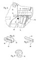
- the attachment of the piston rod 64 of the actuator 34 on the bottom plate 56th about the fork-shaped bracket 54 is based on the figures 3 and 4 recognizable.
- the bottom plate 56 extends at a distance from Cover plate 70 of the discharge device 26 and parallel thereto, so that the crop between the bottom plate 56 and the cover plate 70th is passed through.
- the floor panel 56 is with the Side walls 72, 74 of the discharge device 26 welded.
- a extending between the side walls 72, 74 Stiffening strut 66 is also connected to the floor panel 56 welded.
- the fork-shaped bracket 54 is on the bottom plate 56th welded. Their legs of the console 54 are each with one Opening provided through which the axis 52 extends, the also passes through a bore at the upper end of the piston rod 64.
- the axis 52 is defined by two pins 76, which are outside the Leg of the console 54 through holes in the axis 52nd extend, fixed in position. Between the thighs of the fork-shaped bracket 54 and the piston rod 64 is located each still a punched leg of a U-shaped Spacer 78, the bottom part of the bottom plate 56 abuts.
- the Spacer 78 is shown in FIG.
- the legs of a in the Figure 5 reproduced stop element 80.
- the stop element 80 has a U-shaped profile, wherein in the end region of Leg openings are arranged, through which the axis 52nd extends. In other dimensions of the console 56 and the Stop element 80, the spacer 78 could also be omitted.
- the length of the stop element 80 is dimensioned such that the upper edge of the cylinder of the actuator 34 on the stop element 80th is present when the discharge device 26 in the in the figure 1 marked position, d. H. on the storage device 62 rests and the stop element 80 on the bottom plate 56th is applied.
- the discharge device 26 is then not supported over the piston rod 64 of the actuator 34, but over the Stopper 80 and the cylinder of the actuator 34 on the flange 46th from. If the actuator 34 is double-acting, appropriate measures are required make sure that the piston rod 64 does not retract further as shown here.
- first leg of the Stop element 80 is angled outwards Provided area 82 in which a slot 84 is arranged.
- One Adjusting element 86 with a rectangular cross-section is flat at the angled portion 82 and surrounds the edge between the first leg and the area 82.
- the adjusting element 86 and the region 82 extend in the manner shown in FIG. 3 illustrated position parallel to the floor panel 56, wherein the Adjustment 86 abuts the latter.
- the adjusting element 86 is provided with two holes 88 through which screws 90 both continue to hold the slot 84 in the Stop element 80 penetrate and on the adjustment of the 86th opposite side are secured by nuts.
- the described Mounting allows the adjustment member 86 in the longitudinal direction the slot 84 to move relative to the stop element 80, so that it (with respect to the figure 3) are extended downwards can.
- the adjusting element 86 could also pivot on Stop element 86 may be articulated, in particular about the longitudinal axis one of the screws 90.
- a helical spring 92 extends between the second leg of the stop element 80 and the bottom plate 56 and biases the stopper member 80 in the in the Figures 3 and 4 shown position.
- the stop element 80 is now no longer in its active position between the cylinder of the actuator 34th and the axis 52, but in an inactive position, so that the actuator 34 is still below those in Figures 1, 3 and 4 shown position can be retracted, as in the figure 9 shown.
- the discharge device 26 left or right immediately next to the storage device 62 are positioned. This position is suitable especially for transporting the harvester on a truck, Trailers, railway cars, etc., in which only a limited Height is available.
- the operator Before loading the harvester 10, the operator sets the Actuator 34 thus in the position shown in Figure 8. This may be a Automatically be provided, this position on one appropriate input or the operation of a suitable Switch starts.
- the operator leaves the driver's cab 18 and goes to the immediately behind it Discharge device 26, pivots the stopper 80 and adjusts the adjustment 86. Then he can in the Cab 18 to return and spend the Discharge device 26 in the lowered loading position next to the Arrange storage device 62.
- the harvesting machine 10 can be loaded now easily.
Landscapes
- Life Sciences & Earth Sciences (AREA)
- Environmental Sciences (AREA)
- Harvesting Machines For Root Crops (AREA)
- Harvesting Machines For Specific Crops (AREA)
- Harvester Elements (AREA)
Applications Claiming Priority (2)
| Application Number | Priority Date | Filing Date | Title |
|---|---|---|---|
| DE102004020127 | 2004-04-24 | ||
| DE102004020127A DE102004020127A1 (de) | 2004-04-24 | 2004-04-24 | Erntemaschine mit einer Austrageinrichtung |
Publications (2)
| Publication Number | Publication Date |
|---|---|
| EP1588601A1 true EP1588601A1 (fr) | 2005-10-26 |
| EP1588601B1 EP1588601B1 (fr) | 2008-09-17 |
Family
ID=34939250
Family Applications (1)
| Application Number | Title | Priority Date | Filing Date |
|---|---|---|---|
| EP05102890A Expired - Fee Related EP1588601B1 (fr) | 2004-04-24 | 2005-04-13 | Machine de récolte avec un dispositif de décharge |
Country Status (3)
| Country | Link |
|---|---|
| US (1) | US7343726B2 (fr) |
| EP (1) | EP1588601B1 (fr) |
| DE (2) | DE102004020127A1 (fr) |
Families Citing this family (6)
| Publication number | Priority date | Publication date | Assignee | Title |
|---|---|---|---|---|
| US7806757B2 (en) * | 2008-07-16 | 2010-10-05 | Deere & Company | Dual sided belted unloader |
| US7874899B2 (en) * | 2009-05-18 | 2011-01-25 | Deere & Company | Unload rate control for an unloading system in an agricultural harvester |
| AT510659B1 (de) * | 2010-10-22 | 2012-08-15 | Schrattenecker Franz Ing | Maisspindelwerfer |
| US9272853B2 (en) * | 2013-03-15 | 2016-03-01 | Unverferth Manufacturing Company, Inc. | Weight-based chute control for a farm implement |
| USD908740S1 (en) * | 2019-10-20 | 2021-01-26 | Tirth Agro Technology Private Limited | Sugarcane harvester |
| DE102020132157B4 (de) | 2020-12-03 | 2022-07-28 | Deere & Company | Einteiliges Basiselement für einen Auswurfkrümmer eines Feldhäckslers |
Citations (4)
| Publication number | Priority date | Publication date | Assignee | Title |
|---|---|---|---|---|
| DE3224269A1 (de) * | 1981-07-07 | 1983-03-17 | Alois Pöttinger Landmaschinen-Gesellschaft m.b.H., 8900 Augsburg | Auswurfkruemmer fuer landwirtschaftliche maschinen |
| EP1219153A2 (fr) * | 2000-12-23 | 2002-07-03 | CLAAS Selbstfahrende Erntemaschinen GmbH | Dispositif et méthode pour coordonner et contrôler des véhicules agricoles |
| EP1250832A1 (fr) * | 2001-04-20 | 2002-10-23 | Deere & Company | Dispositif pour contrôler la position d'un dispositif de déchargement d'une machine agricole de récolte |
| US20040053653A1 (en) * | 2002-09-10 | 2004-03-18 | Heinrich Isfort | Method and apparatus for controlling a transfer device, especially for harvested material of a harvesting machine |
Family Cites Families (7)
| Publication number | Priority date | Publication date | Assignee | Title |
|---|---|---|---|---|
| DE264602C (fr) | ||||
| US4742938A (en) * | 1986-06-19 | 1988-05-10 | Niewold D Wayne | Gravity box and auger positioning mechanism |
| DE4403893A1 (de) | 1994-02-08 | 1995-08-10 | Claas Ohg | Vorrichtung zur automatischen Befüllung von Ladebehältern mit einem Gutstrom |
| GB2287633A (en) * | 1994-03-16 | 1995-09-27 | New Holland Belguim Nv | Forage harvester |
| DE19531662A1 (de) * | 1995-08-29 | 1997-03-06 | Claas Ohg | Vorrichtung zum automatischen Befüllen von Ladebehältern |
| DE10021664B4 (de) * | 2000-05-04 | 2004-05-06 | Maschinenfabrik Bernard Krone Gmbh | Erntemaschine, insbesondere selbstfahrender Feldhäcksler |
| DE10240219A1 (de) * | 2002-08-28 | 2004-03-11 | Claas Selbstfahrende Erntemaschinen Gmbh | Vorrichtung zur Steuerung einer Überladeeinrichtung |
-
2004
- 2004-04-24 DE DE102004020127A patent/DE102004020127A1/de not_active Withdrawn
-
2005
- 2005-04-13 EP EP05102890A patent/EP1588601B1/fr not_active Expired - Fee Related
- 2005-04-13 DE DE502005005371T patent/DE502005005371D1/de active Active
- 2005-04-20 US US11/110,472 patent/US7343726B2/en active Active
Patent Citations (4)
| Publication number | Priority date | Publication date | Assignee | Title |
|---|---|---|---|---|
| DE3224269A1 (de) * | 1981-07-07 | 1983-03-17 | Alois Pöttinger Landmaschinen-Gesellschaft m.b.H., 8900 Augsburg | Auswurfkruemmer fuer landwirtschaftliche maschinen |
| EP1219153A2 (fr) * | 2000-12-23 | 2002-07-03 | CLAAS Selbstfahrende Erntemaschinen GmbH | Dispositif et méthode pour coordonner et contrôler des véhicules agricoles |
| EP1250832A1 (fr) * | 2001-04-20 | 2002-10-23 | Deere & Company | Dispositif pour contrôler la position d'un dispositif de déchargement d'une machine agricole de récolte |
| US20040053653A1 (en) * | 2002-09-10 | 2004-03-18 | Heinrich Isfort | Method and apparatus for controlling a transfer device, especially for harvested material of a harvesting machine |
Also Published As
| Publication number | Publication date |
|---|---|
| DE102004020127A1 (de) | 2005-11-24 |
| DE502005005371D1 (de) | 2008-10-30 |
| EP1588601B1 (fr) | 2008-09-17 |
| US20050235623A1 (en) | 2005-10-27 |
| US7343726B2 (en) | 2008-03-18 |
Similar Documents
| Publication | Publication Date | Title |
|---|---|---|
| EP2067399B1 (fr) | Arrangement de réglage de la position d'un tambour ramasseur et d'un élément presseur d'une moissonneuse agricole | |
| EP1106051A1 (fr) | Faucheuse | |
| DE10211706A1 (de) | Austrageinrichtung einer landwirtschaftlichen Erntemaschine | |
| DE602004009338T2 (de) | Landmaschine zum schwaden von auf dem boden liegenden produkten | |
| DE102005016350A1 (de) | Erntevorsatz für landwirtschaftliche Erntemaschinen | |
| DE10142978A1 (de) | Erntevorsatz | |
| DE102005004211A1 (de) | Erntegerät, insbesondere Erntevorsatz für landwirtschaftliche Erntemaschinen zum Aufnehmen und Weiterfördern von Halmfrüchten | |
| EP1068791A1 (fr) | Faucheuse automotrice munie de convoyeurs | |
| EP1618777B1 (fr) | Dispositif de décharge d'une récolteuse agricole | |
| EP1588601B1 (fr) | Machine de récolte avec un dispositif de décharge | |
| BE1028095A1 (de) | Erntevorsatz mit Mulchgeräten zur Bearbeitung von auf einem Feld stehenden Pflanzenstümpfen mit verbessertem Schutz gegen abgeschleuderte Steine | |
| EP1093708A1 (fr) | Dispositif faucheur | |
| DE102008042392B4 (de) | Erntevorsatz für landwirtschaftliche Erntemaschinen | |
| EP2113396B1 (fr) | Ensemble de roue d'appui pour un ramasseur doté d'un blocage automatique en position de transport | |
| EP1738634B1 (fr) | Dispositif de ramassage de produits de récolte ainsi que machine de récolte. | |
| AT513427B1 (de) | Erntewagen zum Aufnehmen und Transport von Pflanzen oder Pflanzenteilen | |
| EP3092890A1 (fr) | Barre de coupe de moissonneuse | |
| DE102019006298B4 (de) | Aufnahmevorrichtung für eine landwirtschaftliche Arbeitsmaschine, landwirtschaftliche Arbeitsmaschine und Arbeitszug mit einer solchen landwirtschaftlichen Arbeitsmaschine | |
| DE102019005662A1 (de) | Auswurfkrümmer für einen Feldhäcksler | |
| DE102006047530A1 (de) | Erntegerät mit teleskopierbarer Fördereinrichtung | |
| DE1755729A1 (de) | Landwirtschaftlicher wagen | |
| DE202007012649U1 (de) | Ladewagen | |
| EP1932415A1 (fr) | Dispositif muni d'une première et d'une seconde unité de travail | |
| DE102022105847A1 (de) | Schwadaufnehmer mit drittem Stützrad | |
| AT500197A1 (de) | Kreiselschwader |
Legal Events
| Date | Code | Title | Description |
|---|---|---|---|
| PUAI | Public reference made under article 153(3) epc to a published international application that has entered the european phase |
Free format text: ORIGINAL CODE: 0009012 |
|
| AK | Designated contracting states |
Kind code of ref document: A1 Designated state(s): AT BE BG CH CY CZ DE DK EE ES FI FR GB GR HU IE IS IT LI LT LU MC NL PL PT RO SE SI SK TR |
|
| AX | Request for extension of the european patent |
Extension state: AL BA HR LV MK YU |
|
| 17P | Request for examination filed |
Effective date: 20060426 |
|
| AKX | Designation fees paid |
Designated state(s): BE DE FR GB IT |
|
| GRAP | Despatch of communication of intention to grant a patent |
Free format text: ORIGINAL CODE: EPIDOSNIGR1 |
|
| GRAS | Grant fee paid |
Free format text: ORIGINAL CODE: EPIDOSNIGR3 |
|
| GRAA | (expected) grant |
Free format text: ORIGINAL CODE: 0009210 |
|
| AK | Designated contracting states |
Kind code of ref document: B1 Designated state(s): BE DE FR GB IT |
|
| REG | Reference to a national code |
Ref country code: GB Ref legal event code: FG4D Free format text: NOT ENGLISH |
|
| REF | Corresponds to: |
Ref document number: 502005005371 Country of ref document: DE Date of ref document: 20081030 Kind code of ref document: P |
|
| PLBE | No opposition filed within time limit |
Free format text: ORIGINAL CODE: 0009261 |
|
| STAA | Information on the status of an ep patent application or granted ep patent |
Free format text: STATUS: NO OPPOSITION FILED WITHIN TIME LIMIT |
|
| 26N | No opposition filed |
Effective date: 20090618 |
|
| PG25 | Lapsed in a contracting state [announced via postgrant information from national office to epo] |
Ref country code: IT Free format text: LAPSE BECAUSE OF FAILURE TO SUBMIT A TRANSLATION OF THE DESCRIPTION OR TO PAY THE FEE WITHIN THE PRESCRIBED TIME-LIMIT Effective date: 20080917 |
|
| PGFP | Annual fee paid to national office [announced via postgrant information from national office to epo] |
Ref country code: FR Payment date: 20120503 Year of fee payment: 8 Ref country code: GB Payment date: 20120425 Year of fee payment: 8 |
|
| GBPC | Gb: european patent ceased through non-payment of renewal fee |
Effective date: 20130413 |
|
| PG25 | Lapsed in a contracting state [announced via postgrant information from national office to epo] |
Ref country code: GB Free format text: LAPSE BECAUSE OF NON-PAYMENT OF DUE FEES Effective date: 20130413 |
|
| REG | Reference to a national code |
Ref country code: FR Ref legal event code: ST Effective date: 20131231 |
|
| PG25 | Lapsed in a contracting state [announced via postgrant information from national office to epo] |
Ref country code: FR Free format text: LAPSE BECAUSE OF NON-PAYMENT OF DUE FEES Effective date: 20130430 |
|
| PGFP | Annual fee paid to national office [announced via postgrant information from national office to epo] |
Ref country code: DE Payment date: 20210319 Year of fee payment: 17 |
|
| PGFP | Annual fee paid to national office [announced via postgrant information from national office to epo] |
Ref country code: BE Payment date: 20210427 Year of fee payment: 17 |
|
| REG | Reference to a national code |
Ref country code: DE Ref legal event code: R119 Ref document number: 502005005371 Country of ref document: DE |
|
| REG | Reference to a national code |
Ref country code: BE Ref legal event code: MM Effective date: 20220430 |
|
| PG25 | Lapsed in a contracting state [announced via postgrant information from national office to epo] |
Ref country code: DE Free format text: LAPSE BECAUSE OF NON-PAYMENT OF DUE FEES Effective date: 20221103 |
|
| PG25 | Lapsed in a contracting state [announced via postgrant information from national office to epo] |
Ref country code: BE Free format text: LAPSE BECAUSE OF NON-PAYMENT OF DUE FEES Effective date: 20220430 |