EP1219153A2 - Dispositif et méthode pour coordonner et contrôler des véhicules agricoles - Google Patents
Dispositif et méthode pour coordonner et contrôler des véhicules agricoles Download PDFInfo
- Publication number
- EP1219153A2 EP1219153A2 EP01128386A EP01128386A EP1219153A2 EP 1219153 A2 EP1219153 A2 EP 1219153A2 EP 01128386 A EP01128386 A EP 01128386A EP 01128386 A EP01128386 A EP 01128386A EP 1219153 A2 EP1219153 A2 EP 1219153A2
- Authority
- EP
- European Patent Office
- Prior art keywords
- vehicle
- harvesting
- transport
- vehicles
- transfer device
- Prior art date
- Legal status (The legal status is an assumption and is not a legal conclusion. Google has not performed a legal analysis and makes no representation as to the accuracy of the status listed.)
- Granted
Links
- 238000000034 method Methods 0.000 title claims abstract description 77
- 238000012546 transfer Methods 0.000 claims description 241
- 238000003306 harvesting Methods 0.000 claims description 217
- 238000012545 processing Methods 0.000 claims description 88
- 230000005540 biological transmission Effects 0.000 claims description 64
- 230000008859 change Effects 0.000 claims description 48
- 230000008569 process Effects 0.000 claims description 24
- 238000003860 storage Methods 0.000 claims description 10
- 239000000463 material Substances 0.000 claims description 5
- 230000004044 response Effects 0.000 claims description 2
- 239000004459 forage Substances 0.000 description 29
- 238000011156 evaluation Methods 0.000 description 23
- 238000004364 calculation method Methods 0.000 description 17
- 238000012937 correction Methods 0.000 description 13
- 238000006243 chemical reaction Methods 0.000 description 12
- 230000001276 controlling effect Effects 0.000 description 12
- 230000006872 improvement Effects 0.000 description 9
- 230000008901 benefit Effects 0.000 description 8
- 238000012544 monitoring process Methods 0.000 description 7
- 230000001419 dependent effect Effects 0.000 description 6
- 230000006870 function Effects 0.000 description 6
- 241001124569 Lycaenidae Species 0.000 description 4
- 238000004891 communication Methods 0.000 description 4
- 238000011161 development Methods 0.000 description 4
- 230000003213 activating effect Effects 0.000 description 3
- 238000001514 detection method Methods 0.000 description 3
- 238000006073 displacement reaction Methods 0.000 description 3
- 239000000428 dust Substances 0.000 description 3
- 238000003754 machining Methods 0.000 description 3
- 230000003287 optical effect Effects 0.000 description 3
- 230000001105 regulatory effect Effects 0.000 description 3
- 230000006978 adaptation Effects 0.000 description 2
- 238000005520 cutting process Methods 0.000 description 2
- 230000007257 malfunction Effects 0.000 description 2
- 238000007726 management method Methods 0.000 description 2
- 238000011022 operating instruction Methods 0.000 description 2
- 230000000007 visual effect Effects 0.000 description 2
- 235000016068 Berberis vulgaris Nutrition 0.000 description 1
- 241000335053 Beta vulgaris Species 0.000 description 1
- 244000025254 Cannabis sativa Species 0.000 description 1
- 231100000681 Certain safety factor Toxicity 0.000 description 1
- 240000008042 Zea mays Species 0.000 description 1
- 235000005824 Zea mays ssp. parviglumis Nutrition 0.000 description 1
- 235000002017 Zea mays subsp mays Nutrition 0.000 description 1
- 230000001133 acceleration Effects 0.000 description 1
- 230000009471 action Effects 0.000 description 1
- 230000004913 activation Effects 0.000 description 1
- 238000013459 approach Methods 0.000 description 1
- 230000002457 bidirectional effect Effects 0.000 description 1
- 238000012508 change request Methods 0.000 description 1
- 239000003795 chemical substances by application Substances 0.000 description 1
- 230000001427 coherent effect Effects 0.000 description 1
- 208000013407 communication difficulty Diseases 0.000 description 1
- 239000012141 concentrate Substances 0.000 description 1
- 238000011109 contamination Methods 0.000 description 1
- 235000005822 corn Nutrition 0.000 description 1
- 238000013500 data storage Methods 0.000 description 1
- 230000009849 deactivation Effects 0.000 description 1
- 230000009365 direct transmission Effects 0.000 description 1
- 230000000694 effects Effects 0.000 description 1
- 230000002706 hydrostatic effect Effects 0.000 description 1
- 230000000977 initiatory effect Effects 0.000 description 1
- 238000005259 measurement Methods 0.000 description 1
- 230000007246 mechanism Effects 0.000 description 1
- 230000002265 prevention Effects 0.000 description 1
- 230000001681 protective effect Effects 0.000 description 1
- 230000036632 reaction speed Effects 0.000 description 1
- 230000035484 reaction time Effects 0.000 description 1
- 239000002689 soil Substances 0.000 description 1
- 238000009827 uniform distribution Methods 0.000 description 1
Images


Classifications
-
- A—HUMAN NECESSITIES
- A01—AGRICULTURE; FORESTRY; ANIMAL HUSBANDRY; HUNTING; TRAPPING; FISHING
- A01D—HARVESTING; MOWING
- A01D43/00—Mowers combined with apparatus performing additional operations while mowing
- A01D43/08—Mowers combined with apparatus performing additional operations while mowing with means for cutting up the mown crop, e.g. forage harvesters
- A01D43/086—Mowers combined with apparatus performing additional operations while mowing with means for cutting up the mown crop, e.g. forage harvesters and means for collecting, gathering or loading mown material
- A01D43/087—Mowers combined with apparatus performing additional operations while mowing with means for cutting up the mown crop, e.g. forage harvesters and means for collecting, gathering or loading mown material with controllable discharge spout
-
- A—HUMAN NECESSITIES
- A01—AGRICULTURE; FORESTRY; ANIMAL HUSBANDRY; HUNTING; TRAPPING; FISHING
- A01B—SOIL WORKING IN AGRICULTURE OR FORESTRY; PARTS, DETAILS, OR ACCESSORIES OF AGRICULTURAL MACHINES OR IMPLEMENTS, IN GENERAL
- A01B69/00—Steering of agricultural machines or implements; Guiding agricultural machines or implements on a desired track
- A01B69/007—Steering or guiding of agricultural vehicles, e.g. steering of the tractor to keep the plough in the furrow
- A01B69/008—Steering or guiding of agricultural vehicles, e.g. steering of the tractor to keep the plough in the furrow automatic
-
- A—HUMAN NECESSITIES
- A01—AGRICULTURE; FORESTRY; ANIMAL HUSBANDRY; HUNTING; TRAPPING; FISHING
- A01B—SOIL WORKING IN AGRICULTURE OR FORESTRY; PARTS, DETAILS, OR ACCESSORIES OF AGRICULTURAL MACHINES OR IMPLEMENTS, IN GENERAL
- A01B79/00—Methods for working soil
- A01B79/005—Precision agriculture
-
- G—PHYSICS
- G05—CONTROLLING; REGULATING
- G05D—SYSTEMS FOR CONTROLLING OR REGULATING NON-ELECTRIC VARIABLES
- G05D1/00—Control of position, course, altitude or attitude of land, water, air or space vehicles, e.g. using automatic pilots
- G05D1/02—Control of position or course in two dimensions
- G05D1/021—Control of position or course in two dimensions specially adapted to land vehicles
- G05D1/0287—Control of position or course in two dimensions specially adapted to land vehicles involving a plurality of land vehicles, e.g. fleet or convoy travelling
- G05D1/0291—Fleet control
Definitions
- the invention relates to a device and a method for coordination and Hiring of agricultural vehicles that are on a common field and especially on self-driving agricultural Vehicles between which crop is overloaded, being between vehicles there is a data transmission link and at least one vehicle with at least one is equipped with a navigation system.
- Self-propelled agricultural vehicles are self-propelled harvesters or Harvesting vehicles, such as combine harvesters or forage harvesters. Furthermore are under self-propelled agricultural vehicles also include transport vehicles, such as a transport team consisting of a towing vehicle and at least an attached transport container or a self-propelled transport vehicle to understand a transport container arranged directly on the transport vehicle.
- the harvesting machines take crops continuously during the harvesting process work on it in a known manner and either give the crop continuously, for example with a self-propelled forage harvester or after a temporary storage, for example, from a combine to a transport container. To this The harvesting machines have a transfer device for this purpose. At a combine the transfer device from a grain tank outlet pipe and at a Forage harvester formed by an exhaust spout.
- the transport vehicle drives next to or behind the harvesting machine during loading.
- overloading unloading the grain tank
- Loss-free overloading without the crop falling next to the transport container and, moreover, the transport container being fully utilized is very difficult when overloading while driving.
- Both vehicles are controlled by one vehicle operator each, the vehicle operator of the harvesting vehicle primarily monitoring the harvesting process continuously and additionally controlling the transfer device.
- the machine operator When monitoring and controlling the transfer device, the machine operator must look away from the harvesting area to the transfer area.
- the coordination of the individual vehicles on the processing field is carried out independently by the respective vehicle operator of the respective vehicle.
- the harvesting vehicle is based on the processing field to be harvested and the crop edges present on the processing field, for example on a grain edge or a swath of grass.
- the other transport vehicles then follow the harvest vehicle on the already harvested processing field.
- the transport vehicle involved in the overloading drives directly next to or behind the harvesting vehicle during the overloading and is oriented on the harvesting vehicle.
- the vehicle operator of the transport vehicle follows the further instructions of the machine operator of the harvesting vehicle for optimally filling the transport container. This is particularly necessary when the setting of the transfer device can no longer be changed to a desired position, for example when the transfer device has reached a stop of the swivel range around the vertical axis of rotation.
- the vehicle operator of the harvesting vehicle can then direct appropriate driving instructions to the vehicle operator of the transport vehicle by means of simple hand signals or via a radio communication link.
- both vehicle operators and possibly also vehicle operators of still further vehicles on the processing field must also pay attention to reactions of the respective other vehicle, which are caused, for example, by difficult harvesting or soil conditions.
- the vehicle operator generally no longer has time to inform the other vehicle of its location, but instead endeavors to rectify the malfunction as quickly as possible.
- the vehicle operators are also particularly stressed at the start of the transfer process, for example when processing is started on a new processing track and / or the transfer device is switched on, because then the trajectory of the crop through the air cannot yet be clearly estimated by the vehicle operators and that respective vehicle operators must adapt the vehicle to the new processing lane at least in the direction of travel and speed, in particular the vehicle operator of the harvesting vehicle has to adjust the harvesting vehicle to the quantity of harvested crop and cannot concentrate on the overloading process at the same time.
- Patent specification DD 155 157 discloses a positioning device between a harvesting vehicle and a transport vehicle.
- the distance between the transport vehicle and the harvesting vehicle is determined by acoustic or optical sensors on the harvesting vehicle on the basis of reflected signals and converted into corresponding operator information.
- the degree of filling of the transport container is also determined by appropriate sensors in the transport container.
- the container is filled accordingly at a certain point, this is indicated to the vehicle operator optically and acoustically on a display device in the driver's cabin. Using these signals, he can control the position of the transport container so that the container is loaded at another, less filled location. If the transport container leaves the area detected by the individual sensors, the transfer device is switched off.
- the proposed solution is based on sensor signals which optically or acoustically determine a distance depending on the transit time of an emitted magnetic wave between the harvesting vehicle and the transport vehicle. This has a negative impact on the reliability of the sensor signals.
- Another device is known from DE 195 31 662 A1, in which the relative Alignment of the transfer device to a transport container by means of optical Distance sensors that are attached directly to the transfer device are determined becomes.
- the transfer device from the harvesting machine should then use the measurement data from the sensors off manually or automatically set for optimal overloading become.
- Various adjustment mechanisms for the transfer device can be used here be resorted to.
- the transfer device is operated by one Chute formed on a self-propelled forage harvester that is horizontal and is vertically pivotally attached to the vehicle.
- a swiveling discharge flap with which the discharge direction of the crop flow can also be adjusted.
- Another such device is known for a self-propelled forage harvester from DE 44 26 059A1.
- a camera is provided here, the image area of which is directed both towards the discharge flap and onto the transport container, the image being displayed to the vehicle operator of the self-propelled forage harvester for controlling the transfer device on a monitor in the driver's cabin.
- All these devices have the disadvantage that they fail if there is dust in the detection range of the sensors. As a result, the optical sensors or the reflectors quickly become dirty and a sufficiently reliable detection of the transport container is then no longer possible.
- the known devices fail when the vehicle operators of the vehicles are inexperienced or inattentive and the transport container is moved into an area that is outside the possible overloading area.
- a device in that at least one navigation system determines at least one position of a vehicle and at least this is transmitted to at least one further vehicle by means of the data transmission path.
- a further solution to the problem is given by a method according to the invention, which is characterized in that at least one position of a vehicle is transmitted to at least one further vehicle.
- the solution proposed according to the invention represents an enormous improvement for improved coordination of vehicles on the processing field and also for the desired, lossless overloading of crop.
- the respective other vehicle receives information about at least one position of another vehicle.
- Another advantage is the close, direct transmission of at least one position to another vehicle.
- the distances between the vehicles on a processing field with one another, in particular the vehicles which are directly involved in the transfer process, are only small.
- a simple, inexpensive and known data transmission device can therefore advantageously be used for the data transmission.
- the position of the respective other vehicle received by means of the data transmission link advantageously enables the vehicle itself to inform certain devices in its own vehicle about the position of the respective further vehicle.
- each vehicle contains its own evaluation, storage or control devices and responds with its own derived reaction as a result of the evaluation of the transmitted position or positions.
- the data transmission link can also be used advantageously for a further data exchange. If, for example, a vehicle receives a position signal from another vehicle in the data transmission area, this signal can also be used as a start signal for mutual identification and subsequent further communication.
- Another advantage of the solutions according to the invention is the possible use of inexpensive satellite navigation systems. These can deliver strongly distorted positions with regard to a terrestrial reference system. However, this is irrelevant for the use according to the invention, since the falsification of the individual position signals on the relative orientation of the positions to one another is the same.
- At least a vehicle has a device in which the data transmission route transmitted position of another vehicle in connection with the Position of the vehicle equipped with the device brought and at least generates a signal for influencing at least one parameter of a vehicle becomes.
- a device is present on at least one vehicle, which derives vehicle operator information from the position of another vehicle transmitted by means of the data transmission link in conjunction with the position of the vehicle equipped with the device, and displays this to the vehicle operator.
- the vehicle operator thus advantageously receives information about the current position, for example of the harvesting vehicle, in relation to the position of the driver's own vehicle and can then monitor or control the relative orientation of the vehicles to one another on the basis of the display. Changes in the relative orientation can then be tracked accordingly and, if necessary, compensated for manually by a corresponding correction of the direction of travel or speed.
- This device can be attached to the processing field in every vehicle, so that the vehicle operator advantageously also receives information about the relative vehicle position to the other vehicles and also about the relative vehicle movements of the other vehicles on the processing field even in the dark.
- the invention can also be configured by a device which makes it possible to display the orientation of the longitudinal axis of the vehicle in relation to the corresponding position of the vehicle.
- An electronic compass the so-called gyrocompass, is particularly suitable for this.
- the respective position of a vehicle can advantageously also be assigned the orientation or also the direction of travel and, if appropriate, also the dimensions of one's own or also of the respective further vehicle, transmitted by means of the data transmission path and correspondingly displayed on a display. Changes in the direction of travel of another vehicle and the respective distances from the other vehicles can thus be easily monitored.
- a corresponding display can easily be arranged in the field of vision of a machine operator.
- the position of the sending vehicle is shifted by a desired distance from the transport vehicle or also by a certain offset in the direction of travel before the transmission and is only then transmitted to the transport vehicle.
- the respective distance or the offset of the shifted position of the respective other vehicle from the current position of the vehicle can be predetermined by one of the vehicle operators or, for example, by means of simple, known control elements.
- at least the vehicle operator of the sending harvesting vehicle without visual or radio connection to the operator of the transport vehicle has the opportunity at any time to send operator information to the transport vehicle by, depending on the operator's request, sending his navigated position shifted by a desired amount prior to transmission.
- the vehicle operator information is independent of the absolute position of the vehicles on the processing field, so it is of secondary importance which of the positions is displayed as the default position and which position is displayed to the respective vehicle operator.
- the own position or the position of the further vehicle in each case can be shifted in the vehicle in which the positions are displayed or can also be shifted in the corresponding device before being transferred to another vehicle.
- a storage device is present on at least one vehicle, preferably on a self-propelled harvesting vehicle, in which at least the current position of the harvesting vehicle or at least one position of the transport vehicle can be stored.
- at least one position of a vehicle is stored sporadically, depending on the path or time, in this memory device. From the current position and a further stored, advantageously the last stored position, the direction of travel of the respective vehicle can be calculated from the direction of the connecting route between the two positions. This advantageously means that a separate device (compass) for determining the orientation (direction of travel) of the vehicle in relation to the current position can be dispensed with.
- At least the lane covered by the respective vehicle can also be calculated according to the invention and, if the vehicle is appropriately equipped, can be displayed to the respective vehicle operator. This can be done directly on the vehicle, which is equipped with the storage device, or also for a later evaluation of the harvesting process on a vehicle-independent computer system. Based on the stored positions, further statements can advantageously be made about the position of, for example, the current position of a transport container attached to a towing vehicle.
- the dimensions of the chassis of the transport container such as its track width, center distance and the relative position of the towing eye, the approximate position of the transport container in relation to the current position can be determined in connection with the back lane of the towing vehicle of the transport vehicle.
- These parameters and the relative position of the transport container can, if necessary, be transferred to the harvesting vehicle during identification and then taken into account when determining the display of the vehicle operator information.
- Driving information is thus given to the vehicle operator of the transport vehicle, which takes into account the specifications and operating instructions of the vehicle operator of the harvesting vehicle and the position of the transport container.
- At least one vehicle has a device for automatically influencing the direction of travel or the speed of travel as a function of the information transmitted by the data transmission path.
- the vehicle operator information according to the invention enables the respective vehicle operator to manually adapt his vehicle in the direction of travel or driving speed to the respective other vehicle. Due to the further configuration according to the invention, this adaptation can also take place at least in part automatically.
- the corresponding vehicle advantageously the transport vehicle, is equipped with devices which enable automatic action on the driving speed and / or on the direction of travel.
- hydrostatic, mechanical, electrical or even combined drive systems of this type are known, which as a rule contain a device in the drive train by means of which the driving speed can be varied in steps or also continuously.
- the device determines a driving speed for the transport vehicle, which is necessary so that at least the position specified by the harvesting vehicle and the current position of the transport vehicle are congruent or at least the relative distance between the vehicles is maintained.
- a controller included in the device serves to control the actuating device, to influence the driving speed and determines a corresponding manipulated variable from a target and actual position comparison.
- the person skilled in the art can use known adjusting devices for regulating the driving speed.
- at least one vehicle has a remote control device. So-called autopilots are known from the harvesting vehicles. These include sensors that scan the relative course of the processing edge or track in front of the harvesting vehicle.
- the autopilot then controls the direction of travel of the harvesting vehicle on the basis of the sensor signal so that the harvesting machine automatically follows the processing edge or track.
- These harvesting vehicles are equipped with an electro-hydraulic steering system and any type of vehicle can be equipped with such a steering system.
- the device according to the invention using the known automatic steering devices, can also be used to control the direction of travel of at least one vehicle.
- the deviations of the driving directions of at least two vehicles from one another can then be automatically corrected by means of this device.
- This type of control of at least two vehicles with respect to one another is particularly suitable for the overloading of harvested crop when driving in parallel or in parallel. In this case, several vehicles can also lead to one another at corresponding intervals based on the respective relative positions.
- the device can at least coaxially display a circle with a radius that corresponds approximately to the desired distance of the positions of the vehicles from one another. This simplifies the monitoring of the relative orientation of the vehicles to one another in that the circle is also shown at least in the vicinity of the further, displayed position. Simplified, the circle cannot be displayed fully, but only by a partial arc that runs in the vicinity of the further position.
- the harvesting vehicle is also advantageously equipped with a device for controlling the driving speed and / or the driving direction. Unwanted slope drift of the vehicles can then occur in poor ground conditions, especially when the machining field piece is on a slope, in the worst case the vehicles moving towards one another.
- the harvesting vehicle is also automatically adapted to that of the transport vehicle, at least in terms of driving speed. This can inevitably take place by an automatic intervention in the driving speed control or by a corresponding driving or warning to the vehicle operator of the harvesting vehicle.
- This embodiment of the device according to the invention also provides effective protection against accidents, in particular when the transport vehicle drives behind the harvesting vehicle, as is necessary, for example, at the start of processing a new processing field with the self-propelled forage harvester.
- a corresponding braking or stop signal can be generated in the corresponding device, transmitted to the transport vehicle and evaluated there accordingly.
- the time required for this only takes a fraction of the reaction time of the respective vehicle operator.
- a device to be present on at least one vehicle, preferably on a self-propelled harvesting vehicle, by means of which the control for coordinating at least one further vehicle can be carried out.
- a further control element for manual control is advantageously present in the driver's cab, by means of which the vehicle operator can manually control the generated further position in its position relative to his own position.
- a joystick is arranged for example in the left armrest of the operator's seat. By moving the joystick forwards or backwards, the vehicle operator of the harvesting vehicle can then change the relative offset of the transport vehicle in the direction of travel of the vehicles, and by moving the joystick sideways, the position specification to the left or right, that is to say the distance.
- a corresponding display in the driver's cab can then show the driver's own position and the other position specifications generated for checking the respective specified position.
- This display can also be used to display at least one current position of another vehicle transmitted to the harvesting vehicle by means of the data transmission route.
- the transport vehicle which receives the position specification by means of the data transmission link, is advantageously controlled by the vehicle operator of the harvesting vehicle by the vehicle operator of the transport vehicle trying to fulfill the position specification.
- the vehicle operator of the harvesting vehicle who is in an elevated position in relation to the vehicle operator of the transport vehicle and can better see the overloading process, is thus able to control the transport vehicle manually for better overloading.
- the vehicle operator of the harvesting vehicle can advantageously directly influence the direction of travel and, if appropriate, also the driving speed of the transport vehicle.
- the automatic control of the transport vehicle can be manually controlled or overridden at any time by the vehicle operator of the transport vehicle. To do this, it does involve a larger deviation between the positions, but can later have this automatically corrected by the controller after reactivating the autopilot. Deactivation of the automatic regulation of the driving speed or the direction of travel of the transport vehicle can be brought about, for example, by manual actuation of the steering wheel or the accelerator pedal or the foot brake.
- the device according to the invention designed in such a way that at least one device on at least one vehicle is available, the relative distance from the respective navigated positions determined between at least two positions of two vehicles.
- the vehicle operator advantageously receives verifiable information about the evaluation of the positions over at least the relative distance to another vehicle.
- the vehicle operator can determine how far another vehicle is from him located on the edit box. So it is recognizable to him especially in the dark, whether it is behind the transport vehicle currently involved in the transfer process there is another transport vehicle.
- the vehicle operator can then, based on the calculated, displayed distance, how far the further can be read Transport vehicle is removed from the harvesting vehicle or the transport vehicle.
- the operator receives from the distance determination and corresponding display of the harvesting vehicle advantageously the possibility that with a previous loading of the corresponding transport vehicle prevailing distance value, between the positions of harvest vehicle and transport vehicle, with a subsequent loading to be able to set again.
- the respective vehicle-related automatically store relative distance values based on a vehicle identifier and with a corresponding overload of crop to this vehicle from the Retrieve storage device again.
- At least one device is present on at least one vehicle and generates a control signal from the determined relative distance to another vehicle in order to control the relative distance of the positions between at least the two vehicles.
- the automatic control advantageously relieves the strain on vehicle operators. For the operator of the transport vehicle, it is only necessary to control the transport vehicle in the vicinity of the harvesting vehicle or another transport vehicle in order then to get a position of the respective other vehicle to control the own vehicle by means of the data transmission link. If a position specification now appears on a display in the driver's cabin of the transport vehicle or if he receives a message that a position specification is present, the operator can decide for himself whether or not to connect to the further vehicle.
- the Position data of all vehicles involved in the automatic coordination in one Device managed and processed on a vehicle.
- the use of the harvesting vehicle is Particularly advantageous as a central facility and this makes another one Improving the workflow through clear, clear driving instructions, one Avoidance of losses, downtimes and collisions achieved.
- the operator of the Harvesting vehicle is advantageously given the option of all vehicles in the vicinity of the To coordinate the harvesting vehicle by means of the control of the specification of the vehicle positions.
- the desired relative distances can continue from the harvesting vehicle of the vehicles among themselves can be determined by the individual target positions accordingly specified and influenced manually by the vehicle operator or retrieved from this from a memory or also from the individual vehicles be kept ready for retrieval by means of the data transmission link.
- certain vehicle constellations that is to say at least two position specifications in a predetermined constellation relating to the position of the harvesting vehicle, have been stored beforehand in a memory. These can then advantageously be called up according to a specific assigned situation and used as a specification for the individual vehicles. Furthermore, central administration and coordination of the individual position specifications advantageously make it possible for the operator of the harvesting vehicle to carry out certain vehicle movements automatically. If, for example, a transport container is filled, the operator of the harvesting vehicle can start the filling of another transport container by an automated change of the transport vehicle.
- the further subsequent transport vehicle is then controlled by means of a changing position specification generated for this vehicle via the data transmission path in such a way that a simple change of the overloading of crop to the further vehicle is made possible.
- the operator of the harvesting vehicle then only has to control the transfer device by means of a control command so that the crop flow is directed from the filled transport vehicle onto the further transport container.
- the started automatic sequence of the vehicle change can then continue for the filled transport vehicle until this vehicle leaves the transmission range of the data transmission route or the transport vehicle now involved in the overloading has reached the optimal transfer position with respect to the harvesting vehicle. Only then can the automated change of transport vehicles be ended.
- the central coordination of the individual vehicles is also particularly advantageous because it allows the individual devices on the other vehicles to be designed in a simple manner.
- the current status of a vehicle can be a further component of the information that can be transmitted via the data transmission path.
- the harvesting vehicle is then given this status in each case assigned to a transport vehicle and, depending on this, a corresponding automatic coordination according to the invention is carried out from the harvesting vehicle.
- a transport vehicle for example when entering the transmission area of the data transmission path of the harvesting vehicle, registers with the central device according to the invention as an empty vehicle.
- This device then generates a position specification for this vehicle in a free area in the vicinity of the harvesting vehicle. At least the positions of other vehicles on the processing field and possibly also the corresponding dimensions of the vehicles are taken into account.
- This vehicle is then given a position by means of the data transmission link.
- the operator of the transport vehicle then has the option of switching on his own autopilot. If this is done, the transport vehicle is automatically controlled depending on its own position and that of the harvesting vehicle. For this purpose, the position on the harvesting vehicle is continuously generated and transmitted to the transport vehicle by the device. This may be shifted beforehand on the harvest vehicle by a predetermined amount. The transmitted position is then constantly compared with one's own position and, in the event of a deviation, an appropriate control signal is generated to reduce the deviation.
- the individual vehicles before starting the automated Coordination first in the desired relative position to the next Vehicle can be moved and then when logging in or when starting the automated Coordination of the existing relative distance recognized as target distance and as Specification for further coordination is set.
- This distance may correspond to this no longer the wish of a vehicle operator, this can advantageously the Interrupt coordination, then manually move the vehicle to a new, desired position control and start the coordination again with the new, existing distance specification.
- At least one vehicle has a device which, at least when specifying a position for coordinating a further vehicle, takes into account at least the current position of the harvesting vehicle and a setting of the transfer device and accordingly uses it as a specification. At least the position of the transfer device relative to the direction of travel or to the longitudinal axis of the harvesting vehicle on the corresponding axis of rotation is detected and made available to the device according to the invention. Since the transfer device itself is present on this harvesting vehicle with the corresponding sensors and control devices, the device for a remote-controlled setting of the transfer device is also advantageously located on this vehicle.
- a relative distance or a position to the vehicle's own position or to the position of the vehicle other vehicle is determined. This means that several distances are determined at the start of the coordination and used as target values for the further coordination. If, for example, the transport vehicle then continues to move forward on the parallel lanes relative to the harvesting vehicle, the device for controlling at least the transfer device can be controlled by pivoting such that the previously determined distance between the navigated position of the transport vehicle and the theoretical point of impact of crop on the transport container is maintained or reappears.
- a setting for the transfer device be derived from at least one position of the harvesting vehicle and the setting of the transfer device.
- a corresponding procedure, which both previous The method includes is also conceivable and can then be particularly advantageous if both vehicles are operated manually.
- a manual change the relative distance between the vehicles then causes a corrected setting the transfer device.
- a change in attitude then effects the transfer device a corrected specification of the position and thus a corrected relative distance between the vehicles.
- the aforementioned method causes advantageously a reaction from the device according to the invention such that the Harvested goods are loaded onto the transport container at about the same location.
- the operator of the respective vehicle left by means of selection and setting options.
- the use of a procedure can also be selected on the basis of the transfer device used and by Art the overload and the associated configuration of the invention Device can be determined.
- the specification of the position for at least the vehicle involved in the transfer process is automatically specified in accordance with the position of the transfer device. This advantageously results in that the operator of the harvesting vehicle can preselect the side of the overloading by means of the setting of the overloading device, based on the position of the harvesting vehicle, on which the transport vehicle to be loaded should travel when overloading crops.
- the selection of the page then automatically specifies the loading direction with respect to the harvesting vehicle and then causes a corresponding generation of a specification for at least one position for at least the transport vehicle involved in the loading process.
- this specification is then transmitted to the corresponding transport vehicle and used in a facility there for coordinating the transport vehicle.
- the operator of the harvesting vehicle is giving away the transfer device to the left when viewed in the direction of travel.
- This position of the transfer device is recognized by the device on the harvesting vehicle and then, in conjunction with the current position of the harvesting vehicle, a position specification for the transport vehicle is generated.
- This specification is generated in relation to the current position of the harvesting vehicle and in accordance with the position of the transfer device, for example, such that the position of the harvesting vehicle is shifted to the left by an amount of 10 m perpendicular to the direction of travel of the harvesting vehicle and by a further amount of 10 m in the direction of travel of the harvesting vehicle and then transferred to the transport vehicle.
- These displacement parameters can be constant default values or, as described above, a distance value.
- the setting of the transfer device can only be taken into account in such a way that only specific transfer parameters such as position transport / transfer, unloading, delivery quantity or speed and possibly Parameters acting on the overloading process from the outside, such as wind or moisture, can be taken into account accordingly by the device according to the invention when coordinating the vehicles.
- a variation of at least one of these parameters only has an influence on the overloading distance at such overloading devices, the relative direction of the overloading relative to the longitudinal axis of the vehicle is constant.
- the setting of the transfer device or the setting-dependent point of impact / transfer point of crop onto the transport container can also be changed in the relative position to the harvesting vehicle during the transfer process, coordination and in particular the specification of a position and at least a relative distance for or between the both vehicles involved in the transfer process, advantageously possible, at least in connection with the position of the harvesting vehicle and the setting of the transfer device.
- the specification of the position is then generated and transmitted to the further vehicle.
- a movement of the transfer device or a change in the setting automatically brings about a change in the transfer position on the transport vehicle and results in a corresponding reaction according to the invention of at least one further vehicle.
- the specification of the position on the corresponding vehicle is changed according to the method in accordance with the change in the setting of the transfer device.
- This method of control is particularly useful if, for example, due to changing processing field properties, such as a changed slope, the operator considers or wishes to change the distance to the transport vehicle as necessary.
- the setting of the transfer device is calculated from at least one position of the harvesting vehicle and from at least one position of a transport vehicle and used for a corresponding setting.
- This method according to the invention advantageously ensures that at least the current position of the transport vehicle is automatically taken into account when setting the transfer device.
- a further improvement of the device according to the invention is achieved in that the transfer device automatically reacts to a changed relative orientation of the vehicles to one another with an automatic correction of the setting of the transfer device, which then also at least allows the point of impact of crop to be maintained on the transport container. If, for example, both vehicles involved in the overloading process are controlled independently of one another, this method advantageously ensures that crops are reliably overloaded onto a transport container.
- Both vehicles are equipped with a navigation device and at least one position is transmitted to the further vehicle by means of the data transmission route. Based on the positions, a relative distance and also a theoretical point of impact of the crop on the transport container can be calculated on the basis of the setting of the transfer device.
- a setting of the transfer device is calculated from the positions of the vehicles, which enables the crop to strike the transport container. For example, both vehicles are controlled by a vehicle operator by hand in parallel driving on a processing field.
- an adjustment of the transfer device is calculated in at least one device on the harvesting vehicle, which results in a point of impact of the crop in the middle of the transport container.
- the transfer device is readjusted or regulated using the method according to the invention in such a way that the point of impact previously achieved is advantageously set again. If the transport container is sufficiently filled at one point, a vehicle operator can manually change the setting of the transfer device or adapt it to the transport container dimensions in such a way that the transport container is filled at another point. Due to the change in the setting of the transfer device, the new desired theoretical transfer point / impact point is advantageously determined in the corresponding device relative to the vehicle positions and the settings of the transfer device and is adopted as the default for the further transfer until a further manual or automatic change of the Overload point takes place. The settings of the transfer device change automatically when the relative distance between the vehicles involved in the transfer process changes.
- a specification for the setting of the transfer device and / or a position specification for at least one transport vehicle is calculated and accordingly for setting or as Default used. This advantageously achieves particularly flexible coordination of the individual vehicles.
- the setting of the transfer device influences the specification of the driving instructions for the transport vehicle and, according to the invention, is also influenced by the position of the transport vehicle. This has the advantage that if the current position of the transport vehicle deviates from the specified position, be it by intentional or unwanted manual vehicle operation or by a control deviation in an autopilot, the setting of the transfer device is automatically adapted to this deviation and thus a possible loss of crop is prevented.
- At least one device is connected to at least one means which detects at least one parameter of the harvesting process, such as the type of crop or the influence of wind, or at least one parameter of a vehicle, such as the transport container dimensions or the vehicle dimensions.
- the calculated setting or the calculated specification is corrected accordingly and only then is it correspondingly adjusted to at least one vehicle or transmitted to at least one vehicle.
- the inclusion of further parameters in the setting of the transfer device or the calculation of a position specification for a further vehicle further improves the automatic control according to the invention, at least of the distance between the vehicles. A more precise calculation of the theoretical point of impact of the crop on the transport container can advantageously be carried out.
- the specific density, structure and material properties of each crop thus flow into the calculation and represent an improvement, at least when determining and specifying the distance of the harvesting vehicle from the transport vehicle.
- the automatic inclusion of at least one parameter also enables the vehicle coordination to be automatically adapted to itself changing parameters of the harvesting process. Changes in the crop moisture or density thus automatically have an influence on the specification of the position on another vehicle, in particular on the transport vehicle currently picking up the crop. It is also provided that the individual vehicle settings of the harvesting vehicle, such as the engine speed, speed of the processing device, intake speed, speed of the throwing accelerator and other vehicle-specific and crop-specific parameters, are taken into account, at least those parameters that have an influence on the conveying and overloading properties of the crop.
- the setting of the transfer device is then changed automatically when the parameter of the transfer process which is additionally taken into account is changed.
- the device according to the invention advantageously reacts with the method according to the invention by changing the setting of the transfer device or specifying the position such that a desired transfer point is approximately maintained. Taking into account the dimensions of the vehicles involved represents a further improvement for the automatic specification of the position for the transport vehicle currently picking up the crop and for the determination of the setting of the transfer device.
- the navigated position, the lane of the transport vehicle and the dimensions of the vehicle can be used determine the area in which the transport vehicle is located in relation to a current position.
- the area in which the transport container is currently located can also be determined.
- the dimensions of the transport vehicle can advantageously be transferred to the device once by means of the data transmission link or each time a coordination is started, which determines a specification of the position for the transport vehicle in relation to the position of the further vehicle, in particular the harvesting vehicle.
- At least one device in a vehicle can additionally be connected to at least one means for determining vehicle-specific variables, such as the driving speed, the payload or the yield, or for determining safety variables, such as the relative minimum distance .
- vehicle-specific variables such as the driving speed, the payload or the yield
- safety variables such as the relative minimum distance
- the inclusion of the yield amount or the current throughput of goods provides a further advantage for the calculation or an estimate of the filling time of a container and the coordination of the transport vehicle and the following empty vehicles which depend on it. It is therefore quite conceivable to advantageously coordinate at least one vehicle based on the overloaded harvest quantity to the transport container of known size. Furthermore, it is advantageously possible to carry out the loading of the transport containers only up to the permissible load or to vary the specification of the position on the transport vehicle involved in the loading process in certain areas in order to achieve a uniform distribution of the quantity of goods on the transport container.
- the vehicle-specific variables can be measured variables or also simple vehicle parameters and can only be transmitted to at least one other vehicle by means of the data transmission link and can be displayed there for information or can also be used there accordingly.
- a change the setting of the transfer device only due to a change in the relative Alignment of the vehicle to each other.
- a calculation can be advantageous the position of the transfer point is eliminated. It just needs to start coordinating of the vehicles are taken care that in this starting moment the overload with an adjustment of the transfer device is carried out, which leads to an overload harvested crop is suitable in the transport container. Is this setting the Overloading device before starting the coordination, the operator of the Harvest vehicle at any time, for example by manually changing the setting the transfer device, change this setting until a satisfactory Setting is reached. This simplified procedure allows the Limit the amount of calculation and the amount of additional sensor devices.
- the specification of the position for the transport vehicle depends on the position of the Harvesting vehicle, the setting of the transfer device, the dimensions of the Transport vehicle and any other parameters available first made in this way the crop is transferred to the center of the transport container.
- this start control is only active until the operator the transfer device a manual correction of the setting of the transfer device or the relative distance or another method for coordination.
- At least one vehicle is preferred on a self-propelled harvesting vehicle, a facility available that with a processing field map of the current processing field in connection stands.
- This processing field map can be in digital form on a data carrier or in a memory in the device according to the invention be present or ongoing to be recorded.
- the overload direction or the coordination of other vehicles on the processing field can be advantageously automatically selected.
- the facility checks based on the existing map and the current position of the harvesting vehicle, in which relative direction to the harvest vehicle at least has already worked Field is located.
- a display device on which the respective own position and the position of another vehicle in connection is displayed with at least part of the edit field map.
- this display device gets the vehicle operator and in particular the operator of the harvesting vehicle has the ability to automatically respond from To be able to understand facilities on at least your own vehicle. Further he can, especially in the dark, the surrounding processing field area, relative View the harvesting vehicle on the display. If the entire editing field on the Display device displayed, this allows a complete overview of everything on the Machining field and the comparison between the machined and the unprocessed field area.
- the display device is a touchscreen monitor, by means of which the vehicle operator of the harvesting vehicle, for example can select a displayed transport vehicle for filling with crop.
- a touchscreen monitor allows easy entry and display of commands to choose from of operating instructions and settings. Any kind of choice can be easily generated in the display and simply by touching the monitor on the selected position. The selection of a vehicle to which crop should now be overloaded by simply touching the position point done on the display surface. This also allows the displayed ones Specification of positions for the coordination of vehicles by one touch the displayed position and then moving it slightly adapt new conditions and wishes of the operator.
- actuating means for manual control on the harvesting vehicle the setting of the transfer device available.
- These actuators can also be carried out several times, so that an actuating means according to the invention can also be arranged on the transport vehicle.
- the respective vehicle operator gets the option directly or by means of the data transmission link to the setting of the transfer device influential increase.
- Manual operations are then changed from automatic to automatic Setting of the transfer device recognized as manual operations and taken into account as correction settings for the transfer device.
- a manual Changing the setting thus causes a corresponding direct change in the Setting the transfer device and has the result that the automatic Control of the transfer device is not interrupted.
- This Direct manual change of the setting of the transfer device causes according to the invention no automatic change of position specification to the other vehicle, but is recognized as a change that is the new basic setting for a following automatically made change of the setting of the transfer device is taken as a basis.
- the operator of the transfer device gets advantageous hereby the possibility at any time, based on the known method, the setting the transfer device to his wishes and the respective harvesting conditions to be able to adapt without the automatic coordination of the invention Vehicles or the automatic setting of the transfer device according to the invention to deactivate.
- a theoretical point of impact of the crop is calculated on the transport container, with at least one position of the Transport vehicle and the corresponding dimensions of the transport container compared and at least generates a warning message when the theoretical point of impact lies outside the transport container.
- the warning by means of is advantageous the data transmission path to the operator of the other vehicle.
- a mutual notification is also advantageous because the transport vehicle, by a corresponding change in the relative orientation of the transport vehicle to the harvesting vehicle or by a corresponding manual operation the overloading device can be the cause of the warning.
- one is used by a vehicle operator intended manual adjustment of the setting of the transfer device respectively the specification of at least one position on another vehicle is then prevented, if this becomes a theoretical point of impact of the crop outside of the transport container would lead.
- This advantageously ensures that the operator the transfer device, with a corresponding actuation of the transfer device, the loading device can not adjust so that crop next to Transport container would be overloaded. This is particularly advantageous for avoidance of incorrect operation and losses if the respective operator has been around for a long time is sitting on the vehicle and is tired or if the contours come in the dark the vehicles can no longer be precisely recognized.
- the setting ranges of the transfer device are now stored in a device, the possible setting of the transfer device for at least one transfer area being assigned in a defined manner to the setting limits which can be detected by means of sensors.
- the defined areas are then advantageously stored, at least in a manner adapted to the mechanical setting limits of the overloading device, the definition of the overloading area also being able to be predefined freely by the operator, meaningfully within the possible setting limits. If the transfer device with its settings is within the defined transfer area, manual or automated actuation of the transfer device changes the setting of the transfer device and does not result in any correction of the specification of the respective position to at least the coordinated transport vehicle.
- the possible overloading area now only extends to a partial area of the transport container, the filling of the areas that are currently inaccessible is made easy by the method according to the invention. If the operator of the harvesting vehicle actuates the means which serve to change the setting of the transfer device manually and then leaves the transfer device the corresponding, defined transfer area, this is recognized on the basis of at least one sensor signal. The wish of the operator of the transfer device is now advantageously converted into a change in the specification of the position for the transport vehicle in such a way that the manual change of the point of impact on the transport vehicle intended by the vehicle operator occurs. This method makes an actuating element for a possible correction of the specification of the position for the further vehicle superfluous.
- the operator of the transfer device can advantageously influence the specification of the position for the further vehicle by means of the actuating elements for the transfer device.
- This method can be further improved in a further embodiment of the invention, in that, according to the invention, the time which elapses until a transport vehicle begins to change the relative distance begins. The improvement is brought about by early initiation of a corresponding correction of the specification of the position for the transport vehicle.
- at least one further area can be defined for this at at least one setting limit within the defined work area / transfer area of the transfer device.
- the transfer device can then continue in the direction of the desired change in the point of impact of the crop on the transport vehicle or the adjustment can then be carried out even further in the required direction. If the desired relative movement of the vehicles is then recognized, the movement of the transfer device is stopped and the desired change in the point of impact on the transport vehicle is only brought about by a corresponding change in the specification of the position on the vehicle.
- a manual change request by an operator of the transfer device advantageously has, irrespective of a corresponding reaction according to the invention, a change speed of change of the point of impact of harvested crop on the transport vehicle which is familiar to the operator.
- the operator of the device also has a means for coordinating the vehicles, by means of which he can choose between different methods for coordinating the vehicles or controlling the transfer device. For example, by actuating a button, actuating the actuating means for controlling the transfer device can be redirected to a corresponding correction of the specification of the position for the further vehicle (transport vehicle).
- the changes carried out according to this procedure interrupt the automatic process at least for the time when the special means according to the invention is actuated and advantageously enable the vehicle operator to intervene in a simple manner in order to quickly respond to special conditions and requirements for coordination on the processing field or to individual requests the vehicle operator to be able to react.
- the means according to the invention can also be provided with further setting options.
- a basic setting of the entire coordination is assigned at least between a transport vehicle and a harvesting vehicle and can then be selected accordingly and set automatically.
- This basic setting includes, for example, setting the transfer device and specifying the position for at least one further vehicle and specifying the method according to which the device according to the invention is to operate.
- automatic coordination is activated according to a first method according to the invention, and further methods are activated, for example, in further positions of the corresponding means.
- a combined means of a button for overriding an automatic system and a rotary switch for selecting the method can also be advantageously provided. Furthermore, a combination of this means according to the invention with an existing touchscreen monitor can also be advantageously implemented. At least one method can then be selected using the touchscreen monitor and assigned to the agent according to the invention. When the means according to the invention are actuated, the reaction is then carried out or the actuations of further means are diverted accordingly or, for example, an automatic change of the transport vehicle is started.
- the means according to the invention also provide at least one operator of a vehicle with the option of assigning the conditions / settings prevailing at the start of a coordination to at least one vehicle to a position of the means and to be able to call them up again at any time.
- At least one navigation antenna is mounted on the harvesting vehicle directly on or at least in the vicinity of the vertical axis of rotation of the transfer device.
- the attachment according to the invention advantageously makes it possible to carry out an improved determination of the transfer direction.
- For an automatic setting of the transfer device it is necessary to generate a target setting and to specify it as such.
- the setting of the transfer device is determined when the coordination or the automatic setting is started and accepted as a further target. Changes in the relative alignment of the positions of the two vehicles to one another are then converted accordingly into a new setting and automatically set.
- a parallel distance between the two lanes can be determined at least from the two positions. This can be used as a distance value and possibly provided with a predetermined offset as a default for the overloading distance.
- the position of at least one point in the transport container or the position of the respective transport container wall can also be determined based on the lane and the known dimensions of the vehicle. This point in the container or the positions of the transport container walls then serve as target or limit values for setting at least the transfer direction. In order to be able to determine a target overload direction, it is necessary to connect a further target position of the harvesting vehicle with this calculated transport vehicle position. Attaching the antenna to the side of the driver's cab facing the transfer device improves this calculation.
- the navigated position of the harvesting machine can then be used directly to determine the direction of the route between the position of the vertical axis of rotation of the transfer device and the further calculated position on the transport vehicle.
- a conversion of the current position of the navigation antenna on the harvesting vehicle to the vertical axis of rotation of the transfer device can then be omitted.
- the target direction for the transfer device is then calculated on the basis of the two target points in relation to a base point or a reference system and advantageously also in relation to the longitudinal direction of the harvesting vehicle.
- the loading direction is then set on the basis of an angle setting of the loading device calculated from the target direction with respect to the longitudinal axis of the harvesting vehicle.
- the calculation effort can be reduced by attaching the navigation antenna according to the invention and the accuracy can be further improved. Furthermore, the movement of the harvesting machine about the respective longitudinal, transverse and vertical axes is recognized directly and can be included in a corresponding correction of the loading direction. Additional sensors which determine the various movements of the harvesting machine can then advantageously be dispensed with. This advantageous attachment of the navigation antenna can also be achieved by a simple, protruding bracket on the rear side of the driver's cab or by directly attaching the navigation antenna to the axis of rotation of the transfer device.
- At least one navigation antenna is attached to the transfer device on the harvesting vehicle.
- the computation effort for determining the direction of overloading, an overloading point or the point of impact of the crop into the transport container can be further reduced. If the end of the transfer device is above the transport container for optimal overloading, as is the case, for example, when transferring crop from a combine to a transport vehicle, and if at least one navigation antenna is attached to this side of the transfer device, this is only for automatic control to ensure that this navigation antenna is located above the target position calculated from the navigation antenna of the transport vehicle in the transport container.
- the relative orientation of the harvesting vehicle to this navigation antenna is of minor importance.
- the coordination of at least one vehicle depending on this navigation antenna is advantageously possible in a simplified manner.
- this antenna position then only has to be shifted by an amount in the direction of travel of a vehicle. If the transfer device reaches a setting limit and a further setting beyond this limit is recognized as necessary, a previously described correction of the specification of the position on the transport vehicle can be initiated according to the invention.
- at least one further navigation antenna can also be attached to the harvesting vehicle, for example on the vertical axis of rotation and / or on the well-dispensing side of the transfer device. If there is a first navigation antenna on the transfer device on the good-delivering side and a further navigation antenna also in the vicinity or directly on the vertical pivot point of the transfer device, the direction of the distance between the two position points corresponds to the current transfer direction.
- a determination of the current orientation of the harvesting machine in the reference system and a corresponding calculation of the transfer direction in connection with a corresponding angle sensor at the connection point of the transfer device to the harvesting machine can be dispensed with entirely.
- the overload direction can thus be calculated directly on the basis of two antenna positions in the terrestrial reference system.
- a conversion between the target transfer direction and the angle between the harvesting machine and the transfer device can then advantageously be omitted. This reduces the calculation effort and the resulting lower reaction speed of the device.
- At least one transport vehicle at least one navigation antenna attached to the transport container. Consequently there are, for example, two navigation antennas on the transport vehicle.
- the navigation antenna on the driver's cab for the coordination of the vehicles and the antenna on the transport container for more precise location of the container and the automatic control derived therefrom, at least the setting of the transfer device on the harvesting vehicle, are advantageously provided.
- a more precise determination of the position of the transport container is achieved, this being made possible in particular by navigating at least one position of a transport container wall directly.
- Based on the known dimensions and the known orientation of the container in relation to the navigated position on the transport container an exact determination of the position and the limits of the transport container is made possible. This simplifies the calculation effort for determining the relative position of the transport container and improves the accuracy of the determination.
- each determined position on the transport container can then be assigned to a wall and the exact course of the wall determined and possibly displayed.
- four navigation antennas are arranged on each wall, the respective position is determined and transmitted to at least one device in the harvesting vehicle by means of the data transmission path.
- the coherent course of the transport container walls is then calculated in the device and this is then displayed for further calculations and possibly also on a display device.
- two navigation antennas are attached to diagonally opposite corner points of the transport container. Due to the smaller number of navigation antennas, the costs can be reduced and the respective equipment of the transport vehicle and the amount of data transmitted can be reduced. Furthermore, through this embodiment of the invention, the number of dimensions of the transport vehicle to be specified, known and possibly also stored in a device, is reduced to a necessary level or even unnecessary. On the basis of a known container shape and the alignment of the two determined positions with respect to one another and on the basis of their direction of movement, the respective position of a transport container wall can be clearly assigned. The specification of a width or length can therefore be omitted entirely.
- each transmitted vehicle position can be provided with a corresponding identifier.
- a position to indicate the current vehicle position for coordinating the vehicles from the signal of at least one navigation antenna on the transport container, and in particular the signal from the antenna which is furthest in the direction of travel.
- At least one navigation system and the device for data transmission is designed as a mobile unit.
- This unit can consist of a housing with a integrated navigation system and a transmitting and receiving device for the Data transmission must be established.
- a navigation antenna on the outside and attached a radio antenna.
- fasteners such as brackets or magnetic feet, for connecting the unit to the Vehicle.
- This unit also includes its own energy supply or an interface for a supply from the vehicle. Become several Navigation antennas used on a vehicle, so the mobile unit can be equipped with connection means for connecting additional navigation antennas.
- the unit is used on a transport vehicle before processing a field piece installed and put into operation.
- Each unit then advantageously has its own identifier. This can then the central coordination facility on the Harvest vehicle communicated and then other dimensions corresponding to the transport vehicle or specification for vehicle-specific coordination can be added.
- On the unit can further display means at least for the display of the function of the Unity.
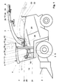
- a self-propelled forage harvester 1 is shown in side view in FIG.
- the latter picks up crop from the processing field via the crop pick-up device 2, comminutes it and delivers it to a transport container by means of the transfer device 3.
- the self-propelled forage harvester 1 has a driver's cab 4.
- This driver's cab 4 there is a seat 5 with a multi-function handle 7 attached to the armrest 6.
- the multi-function handle 7 is equipped with several operating buttons and switches. The vehicle operator can use these control buttons and switches to influence the function and setting of the vehicle remotely using existing drives.
- he can adjust the height of the crop receiving device 2 to the processing field, pivot the transfer device 3 about the vertical axis of rotation 10, control the direction of the loading flap 9 or change the height of the transfer device 3 about the horizontal axis of rotation 15.
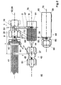
- Further controls can be arranged on the existing multifunction handle 7 or on a further control element in the form of a joystick directly on the seat 5, on another armrest or in the operator console 14 located next to the seat. These then serve, for example, for manual specification or for correcting a specification of the position for at least one further vehicle and / or for controlling the coordination of vehicles 1 on the processing field.
- control elements 13, 16 such as switches or rotary setting elements and display elements 17 and, depending on the equipment of the vehicle 1, if necessary also a monitor 20 or one or more LCD displays.
- a foot switch for activating or deactivating at least one device of the device according to the invention.
- At least one evaluation electronics (not shown in detail) and further devices for vehicle control can also be located in the operator console 14. Via the individual control elements 13, 16 or 7, the vehicle operator can carry out the settings of the harvesting vehicle 1 directly by means of electrohydraulic actuators and other drives. By actuating a switch 13 on the operator console 14, the loading height can be set by the vehicle operator, for example.
- the switch signal of the switch 13 controls a hydraulic valve (not shown in any more detail), which then delivers an amount of oil to the hydraulic cylinder 24 and thus increases the good-delivering side of the transfer device 3.
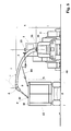
- 1 shows two different positions of the transfer device 3. A working position and a transport position. In the transport position of the transfer device 3, the transfer device 3 is placed on a bracket 22. This position of the transfer device 3 is detected by a switch 23 and reported to an electronic evaluation system.
- Located on the horizontal axis of rotation 15 of the transfer device 3 is a sensor 25 which determines the relative position of the transfer device 3 with respect to the harvesting vehicle 1, that is to say can be used for determining the transfer height.
- the setting of the loading flap 9 is predetermined by the position of the hydraulic cylinder 12 and detected by means of a further sensor 19.
- the sensor 19 thus determines a relative angular position or the relative discharge direction of the transfer device 3 with respect to the transfer device 3. For example, using a button on the multifunction handle 7, the vehicle operator can change the direction of the transfer flap 9 manually and thus control the transfer width.
- the respective position of the transfer device 3 or the transfer flap 9 detected by the sensors 19 and 25 is transmitted to an evaluation electronics. In conjunction with the known height of the horizontal axis of rotation above the processing field and the further dimensions of the transfer device 3, this can then determine a theoretical transfer width and display it to the vehicle operator via the monitor 20 or a corresponding LCD display or use it in a device according to the invention.
- the direction of transfer of the transfer device 3 can be changed remotely by the vehicle operator, for example by actuating a further button on the multifunction handle 7.
- the transfer direction is then pivoted about the vertical axis of rotation 10 by means of a corresponding control of the hydraulic drive 27, the output of which engages in a ring gear 28.
- a sensor 29 detects the respectively set loading direction of the loading device 3 relative to the self-propelled forage harvester 1.
- the current position of the harvesting machine 1 on the processing field is determined using a navigation device.
- a satellite navigation device is used as the navigation device. Navigation systems are suitable for this purpose, which can determine a relative position of the vehicle 1 with respect to a fixed point or a reference system.
- a navigation system based on the triangulation principle is suitable, which determines the position of the vehicle 1 on the processing field on the basis of two determined distances to two fixed, spaced, known positions.
- a satellite navigation system suitable for mobile use such as the GPS navigation system, is particularly suitable.
- the determined position of a vehicle 1 is transmitted to at least one further vehicle by means of a data transmission link.
- This data transmission link can be a simple radio link. However, it is preferably designed as a bidirectional radio link with a short range.
- the harvesting vehicle 1 is equipped with a simple radio device which transmits the position of the harvesting vehicle 1 within a radius of 50 m around the radio antenna 8.
- a transport vehicle can automatically receive the position of the harvesting vehicle 1 if the transport vehicle is appropriately equipped with a radio receiver.
- the transport vehicle can in turn be equipped with a radio antenna or with a navigation system and send its own or the received position within a certain radius.
- a GPS antenna 35 is arranged on a holder 31 directly on the vertical axis of rotation 10 of the transfer device 3.
- the attachment position of the antenna 8 indicates the respective position in the reference system determined by the navigation system, representative of the respective vehicle 1.
- a further GPS antenna 36 can, if necessary, also be attached to the side of the transfer device 3 that delivers the crop.
- GPS antennas 35, 36 can also contain devices for receiving a correction signal for the respective navigated position and are then called D-GPS antennas 35, 36.
- the self-propelled forage harvester 1 is also equipped with at least one further device 34 for determining the orientation of the harvesting machine 1 in a reference system, for example with an electronic compass.
- This device 34 can be expanded by further devices for determining movements and orientations of the harvesting vehicles on the processing field, such as inclination or acceleration sensors.
- a wind measuring device 26 is also attached to the transfer device 3, for example freely swinging about at least one horizontal axis.
- the individual devices in a vehicle 1 can be connected to one another with the further electronic controls, for example via a vehicle bus system.
- Further information about the current settings of the self-propelled forage harvester 1, for example about the position of the crop receiving device 2, the status of the individual drive devices or about working parameters, such as the driving speed, the crop throughput or the crop moisture, are determined by means not shown and can be transmitted to an electronic evaluation system the bus system can be made available.
- a computer system (not shown) can also be installed on the self-propelled forage harvester 1. This evaluates the individual parameters of the harvesting machine 1 and then displays them graphically on an LCD display 17 or the monitor 20.
- a known, available transmission medium can also be entered into this computer system 63, even before the processing field begins to be processed a processing field map can be saved or recorded during processing.
- the relative position of the harvesting machine 1 to said processing field is then continuously determined by the computer system 63 using the navigation device on the basis of the current navigated position.
- a processing field map stored in a memory can be selected partially or completely automatically and displayed on the monitor 20.
- the vehicle operator Before processing the processing field, the vehicle operator normally swings the transfer device 3 from the transport position into a working position.
- the device according to the invention is automatically activated when the self-propelled forage harvester 1 is located directly at the boundary of the processing field and the vehicle operator switches on at least one work unit, for example the chopper drum or the crop pickup device 2.
- the transfer direction 3 is then automatically aligned on the basis of the possible travel areas available for a transport vehicle.
- the monitor 20 can be used to display an existing processing field map and, relative thereto, a schematic representation of the harvesting vehicle 1 as well as to display further vehicles and to display vehicle settings and harvesting parameters. In the embodiment of the monitor 20 as a touchscreen monitor, settings and specifications can then also be carried out using the monitor 20.
- activated devices and selected methods can take place by means of suitable display elements 17 or also, for example, by a corresponding symbolic display on monitor 20.
- An antenna 8 is located on the roof of the driver's cab 4. This antenna 8 is used for communication with at least one other vehicle on the processing field and is at least part of the data transmission path and suitable for receiving or transmitting a position from or to another vehicle and, if appropriate, also suitable to transmit a received position to another vehicle.
- a device 11 is assigned directly to the antenna 8, which takes over the control of the data transmission and also serves as an interface between the data transmission path and the further vehicle devices.
- FIG. 2 shows a plan view of three vehicles on a processing field.
- a first vehicle is designed as a self-propelled forage harvester 1.
- This harvesting vehicle 1 picks up harvested crop 41 previously merged on the processing field 40 from there by means of a pickup device 42 and, after processing, transfers it to a first transport vehicle 43 located in the lane 70.
- This vehicle 43 consists of a towing vehicle 45 and one already Attached transport container 47 partially filled with crop 54.
- Another transport vehicle 44 is shown as a trailer vehicle with a towing vehicle 60 and an unfilled transport container trailer 65.
- This transport vehicle 44 moves in a further lane 75 with the other vehicles 1, 43 and is ready for subsequent overloading of the crop.
- the coordination of these vehicles 1,43,44 takes place according to the so-called master-slave principle.
- the harvesting vehicle 1 is the master vehicle, the direction of travel of which is predetermined by the crop swath 41 and then also indicates at least the direction of travel of the two slave vehicles 43, 44 based on its own position.
- the individual longitudinal directions of the vehicles 1, 43, 44 and those of the transport containers 47, 65 lie here on the respective processing and driving lane 52, 70, 75 and are also parallel to the further processing and driving lane, 52, 70, 75 further Vehicle 1,43,44.
- the harvesting vehicle 1 is equipped with an antenna 8 and a GPS antenna 35.
- this vehicle 1 transmits its currently navigated position to the transport vehicle 43 as a specification.
- the latter receives this position specification using its own antenna 81 and brings this specification into a device with its own position navigated using the GPS antenna 37.
- the relative orientation of the two positions is then used to generate driving instructions or also for automatic lane guidance and right-of-way control of vehicle 43.
- the generation of the respectively required signal is carried out on the basis of a relative position specification.
- a vectorial specification or a specification of the relative distance in the form of a distance value y and a distance value x between the two positions in relation to the longitudinal direction of the vehicle 43 can be used for this.
- these values x and y can be determined once and then used as a default.
- the determined position of the transport vehicle 43 can also be transferred to the harvesting vehicle 1. It can be provided that an adjustment of the transfer device 3 is calculated and automatically adjusted based on the position of the transport vehicle 43 and the position of the harvesting vehicle 1.
- a desired point of impact 51 of crop on the transport container 47 can be determined in connection with the two position and at least two further vehicle-related distance values.
- a first distance value indicates the distance between the antenna 37 and the point of impact 51 on the transport container 47 and the second distance value indicates the distance between the antennas 35 and the vertical axis of rotation 10 of the transfer device 3.
- the required transfer width between the point of impact 51 and the vertical axis of rotation 10 can also be determined from the length of the route between the two shifted positions and a corresponding setting of the transfer device 3 can be initiated.
- the possible overloading range is specified in the pivoting range of the overloading device 3 about the vertical axis of rotation 10 in a direction from the setting limit 71.
- a further freely selected setting of the transfer device 3 is indicated by the line 72. If the transfer device 3 crosses the line 72 or reaches the setting limit 71, corresponding settings and specifications are caused on the agricultural vehicles according to the given method.
- a GPS antenna 38 and 39 are attached to the transport container trailer 65 at diagonally opposite corner points of the container walls. Antennas 38 and 39 communicate with a device attached to the front container wall.
- This device can be a mobile unit 83 and contains a transmitting and receiving device and an antenna 85 for data exchange with at least one other vehicle.
- a data storage device with specific information about the transport vehicle 44 and possibly further connection devices to further devices in the vehicle can be a further component of this device.
- FIG. 3 shows a self-propelled forage harvester 1 on a processing field 40, which in this case harvests corn 41 from the processing field 40 with the crop pick-up device 2, chops it and, by means of the transfer device 3, transfers it to a transport container 47 drawn by a towing vehicle 45 against the harvesting direction 46.
- the transfer direction and width of the transfer device 3 is calculated on the basis of the navigated position of the self-propelled forage harvester 1 and a further position transferred from the mobile unit 83 to the harvesting vehicle 1 by means of the data transmission link 86 and set accordingly.
- the setting of the transfer device 3 determines the flight direction of the crop 48 delivered to the good-delivering side of the transfer device 3.
- a GPS antenna 87 is attached directly to the mobile unit 83.
- this unit 83 is connected to further devices 101, 77 on the transport vehicle 43 via the lines 90.
- a device 76 on the harvesting vehicle 1 which is provided with an operator terminal 100 and is also connected to the other devices in the vehicle.
- the position of the harvesting vehicle 1 navigated by means of the GPS antenna 35 is displayed by the device 76 on the operator terminal 100 in the form of a circle 92 and in connection with the relative harvesting direction 46 in the form of an attached arrow.
- the operator of the harvesting vehicle 1 can select a method for coordinating the vehicles 1, 43 using the operator bar 93 and can also use this to enter any necessary information. Using another operator bar 94, the settings of the transfer device 3 can be selected and possibly also corrected manually.
- an overload in the direction opposite to the harvesting direction 46 was selected and this is indicated by a corresponding arrow 95.
- a shift of the position of the harvesting vehicle 1 by 15 m against the harvesting direction 46 was selected here for a specification of the position for the transport vehicle 43.
- a corresponding display 96 of the selected displacement distance and a relative, symbolic representation 97 of the default position is carried out on the operator terminal 100.
- the specification of the position for the transport vehicle 43 is transferred to the mobile unit 83 and connected to the navigated position of the transport vehicle 43 in a further device 77 and corresponding operator information is generated.
- An operator display 101 which is connected to the device 77, is arranged in the driver's cabin of the transport vehicle 43.
- the display 101 there is an operator bar 93 for operating the display 101 and in particular for selecting the display size of the symbols 98, 99, 102 and the processing field area.
- the received default position is shown in the form of a circle symbol 98.
- the position of the transport vehicle 43 is displayed in the form of a point 99.
- the vehicle operator now has the task, by means of a corresponding control of the vehicle 43, of carrying out the relative orientation of his vehicle 43 to the harvesting vehicle 1 in such a way that the two symbols 98 and 99 overlap. That is, the point 99 is displayed within the circle symbol 98 when the position is specified.
- the device 77 can also generate driving instructions for the vehicle operator in the form of the arrow 102 shown or also acoustic information.
- the transmitted position 98 can be displayed directly on the operator terminal 101, that is to say without a prior shift.
- a circle with a radius which corresponds approximately to the desired distance of the positions of the vehicles 1.43 from one another is then advantageously displayed coaxially to the position shown. This then simplifies the monitoring of the relative orientation of the vehicles 1, 43 to one another in that the circle is also shown at least in the vicinity of the further, indicated position 99 of the transport vehicle 43.
- the circle can then also not be displayed fully, but only by a partial arc that runs in the vicinity of the further position 99.
- the device 77 can also be connected to a vehicle management system to relieve the vehicle operator, for automatic lane guidance and right-of-way control.
- FIG. 4 shows a top view of a self-propelled forage harvester 1 during a rearward overloading of crop 48 onto a subsequent transport vehicle 43.
- the self-propelled forage harvester 1 has picked up crop from the processing field 40 along the processing track 52, processed it and transferred it to the transport container 47 by means of the transfer device 3 via the towing vehicle 45.
- the transport container 47 is already partially loaded with crop 54.
- the processing field 40 is pierced, for example for dividing a processing field 40 into several partial fields to reduce empty runs at the end of the processing field, there is an overload of crop material 48 a transport container 47 only possible in the manner shown.
- a position of the harvesting vehicle 1 is determined by the GPS antenna 35 on the cabin roof of the harvesting vehicle 1 and a position of the transport vehicle 43 by the GPS antenna 37 on the cabin roof of the towing vehicle 45.
- the position of the transport vehicle 43 is continuously transferred to the harvesting vehicle 1 by means of the data transmission link 80 and the associated antennas 8 and 81.
- the respective positions of the vehicles 1, 43 are stored in the storage device 32 on the harvesting vehicle 1.
- the lane 70 of the transport vehicle can be determined from the individual stored positions 49, 50.
- the position of the vertical axis of rotation 10 of the transfer device 3 is calculated by an amount a from the current position of the harvesting vehicle 1 and a corresponding shift on the longitudinal axis 56 of the harvesting vehicle 1. Since an attached transport container 47 generally follows approximately the lane 70 of the towing vehicle with only slight changes in the direction of travel, the lane 70 of the towing vehicle 45 and the current position of the transport vehicle 43 can also provide information about the current position of the transport container 47 on the Machining field 40 can be made. A desired point of impact 51 and the permissible transfer area of crop 48 onto the transport container 47 is given by the current position of the transport vehicle 43, the known dimensions of the vehicle 43, the transport container 47 and the recorded lane 70 of the transport vehicle 43.
- any desired point of impact 51 can then be specified and selected as a specification.
- FIG. 5 shows a self-propelled forage harvester 1 when crop 48 is overloaded onto a transport vehicle 43 from the side.
- the transfer point P lies in a plane M which is predetermined by the upper edges of the transport container walls. This level M is predetermined by the relative position of the transport vehicle 43 on the processing field 40 and can consequently be determined from the current position of the transport vehicle 43 on the processing field 40 and from the known dimensions, such as the width g and the height h and length of the transport container 47, determine.
- the overload point P itself is formed by the point in the plane M at which the overloaded crop 48 penetrates this plane M.
- the overload point P can be determined from a calculation of the relative position of the point A to the current GPS position 35 of the harvesting vehicle 1, the delivery angle a and the relative position of the plane M to the current GPS position 35 of the harvesting vehicle 1.
- the position of the delivery point A and the delivery angle ⁇ can be calculated from the settings and dimensions of the harvesting vehicle 1.
- the discharge height above the processing field 40 is predetermined by the height i of the horizontal pivot axis 15 above the processing field 40 and the distance k between the horizontal pivot axis 15 and the point A.
- the distance f is predetermined by the position of the well-dispensing side at point A and the vertical axis of rotation 10 of the transfer device 3.
- the relative position of point A to the current GPS position 35 of the harvesting vehicle 1 depends on the current setting of the transfer device 3.
- the calculated plane M and the position of point A can be set in relation to one another on the basis of the respective known position.
- the loading point P can be calculated relative to the individual positions of the vehicles 1, 43. From the current positions of the vehicles 1, 43, the associated lanes and the respective vehicle dimensions, it is also specified where in the plane M the individual transport container walls are located, relative to the loading point P.
- the corresponding evaluation then serves in further facilities for setting and coordinating the respective agricultural vehicles 1.43.
- a combine 120 is opened when crop 125 is overloaded from the side a transport vehicle 43 is shown.
- Combine 120 takes up by means of the cutting unit 121 grain 122 from the processing field 40, threshes it and stores it harvested grain in a grain tank 126 between. Then, if necessary, the content of the grain tank 126 by means of the transfer device 124, during a lateral overload overloaded on the transport container 47.
- the transfer device 124 is a GPS antenna 119 is attached to the end that delivers well. The determined position is then continuously from a device on the combine 120 to a predetermined Amount e shifted and then at least as a distance default the data transmission link 80 to the transport vehicle 43.
- the specification is made to the operator in connection with a position of the transport vehicle 43 of the transport vehicle 43 is displayed and is used for manual and, if necessary also for automatic coordination of at least the distance between the two Vehicles 43,120.
- the data transmission link 80 is also particularly suitable for this type of overload, for data exchange of further data and in particular for the exchange of determined on the combine 120 the respective content of the Grain tanks 126 corresponding crop parameters, such as moisture or the amount.
- FIG. 7 shows an exemplary embodiment of the schematic structure of the device for coordinating vehicles and controlling the transfer device.
- An evaluation electronics 30 is mounted in the operator console 14 in the driver's cab of the self-propelled harvesting vehicle and also includes, for example, a navigation device 61 and a storage device 32.
- the evaluation electronics 30 is for exchanging data or parameters with the other electrical devices or sensors in the harvesting vehicle 1, 120, connected to devices for determining the driving speed or to devices for determining parameters of the crop, such as crop throughput, via a bus connection 62 and possibly to a computer system 63.
- the evaluation electronics 30 receives commands for activating devices or for manual control of the transfer device 3.
- An activation and The device can also be operated using a touchscreen monitor 20.
- the settings and specifications can also be displayed on an existing monitor 20 or on display elements 17. If the device is activated or deactivated, this can be indicated to the vehicle operator by an acoustic signal, for example by a buzzer 18.
- the rotating element 16 in the driver's cab 4 is used, for example, for the variable specification of values, for example for the specification of a distance for a displacement of the position for the specification of this position for a further vehicle 1, 43, 44, 120.
- the correction of the wind influence can also be derived from the signals of a wind measuring device 26.
- the overloading range is determined by the evaluation electronics 30 in conjunction with the signals from the sensors 19 and 25 for detecting the setting parameters of the loading device 3 and further stored parameters of the harvesting vehicle 1. Since the actual loading range is dependent on the parameters of the harvested crop 48, 125, these can be the determination of a setting can also be taken into account by connecting further sensors 33, such as a crop moisture sensor, to the evaluation electronics 30.
- the relative position of the transfer device 3 to the longitudinal axis 56 of the harvesting machine 1 is detected by the sensor 29 and transmitted to the evaluation electronics 30. This sensor 29 also serves as an actual position indicator when the overload direction 64 is controlled or regulated by means of the hydraulic drive 27.
- the respective position of the transfer device 3 can be displayed to the vehicle operator on a monitor 20, on an LCD display 17 or also on a pointer instrument.
- the current position of the harvesting vehicle 1 on the processing field 40 is determined by at least one navigation device 61.
- at least one GPS antenna 35 is connected to the evaluation electronics 30 or to the navigation device 61.
- second GPS antenna 36 there is a further, corresponding connection option available.
- the evaluation electronics 30 are further assigned a transmitting and receiving device 11 as an interface and for controlling a data transmission path 80 to a mobile unit 83 on another vehicle 43, 44, 120 on the processing field 40. Information can then be transmitted between antennas 8 and 85 and in particular a position of a vehicle 1, 43, 44, 120 to another vehicle 1, 43, 44, 120.
- the mobile unit 83 itself contains a transmitting and receiving device 115 for controlling the data exchange by means of the data transmission path 80. It is also equipped with a navigation device 116 including a GPS antenna 87. Mobile unit 83 is connected via at least one line 90 to further devices in a vehicle 43, for energy supply and for an exchange of data, such as positions, settings and parameters. A device 77 enables this connection and further processes the received data / position with the position determined by the mobile unit 83, into corresponding signals for display on an operator display 101 and for further use in other devices on the vehicle 43, 44, 120 a corresponding connection to a bus system 117.
- the vehicle 1, 43, 44, 120 can be shown schematically on a monitor 20 or operator terminal 101.
- a compass 34 is connected to the evaluation electronics 30. In this way, in conjunction with the current position of the harvesting vehicle 1, the longitudinal axis 56 can be determined and displayed accordingly.
- the device and the method according to the invention are not limited to the agricultural vehicles 1,43,44,120 shown in more detail, but can, at a corresponding equipment of a self-driving vehicle 1,43,44,120, too for each type of overloading of crop 48.125 on a subsequent transport container 47 can be applied.
- the device and the method can then also be used apply to control the transfer device when a transport container 47 directly attached to a self-propelled harvesting vehicle 1 or in a special embodiment is also saddled directly on the self-propelled harvesting vehicle 1.
Landscapes
- Life Sciences & Earth Sciences (AREA)
- Engineering & Computer Science (AREA)
- Environmental Sciences (AREA)
- Mechanical Engineering (AREA)
- Soil Sciences (AREA)
- Physics & Mathematics (AREA)
- Radar, Positioning & Navigation (AREA)
- Remote Sensing (AREA)
- Aviation & Aerospace Engineering (AREA)
- General Physics & Mathematics (AREA)
- Automation & Control Theory (AREA)
- Guiding Agricultural Machines (AREA)
- Catching Or Destruction (AREA)
- Control Of Position, Course, Altitude, Or Attitude Of Moving Bodies (AREA)
- Management, Administration, Business Operations System, And Electronic Commerce (AREA)
- Tires In General (AREA)
- Soil Working Implements (AREA)
- Sowing (AREA)
Applications Claiming Priority (2)
| Application Number | Priority Date | Filing Date | Title |
|---|---|---|---|
| DE10064862A DE10064862A1 (de) | 2000-12-23 | 2000-12-23 | Vorrichtung und Verfahren zur Koordination und Einstellung von landwirtschaftlichen Fahrzeugen |
| DE10064862 | 2000-12-23 |
Publications (3)
| Publication Number | Publication Date |
|---|---|
| EP1219153A2 true EP1219153A2 (fr) | 2002-07-03 |
| EP1219153A3 EP1219153A3 (fr) | 2004-02-04 |
| EP1219153B1 EP1219153B1 (fr) | 2006-02-08 |
Family
ID=7668867
Family Applications (1)
| Application Number | Title | Priority Date | Filing Date |
|---|---|---|---|
| EP01128386A Expired - Lifetime EP1219153B1 (fr) | 2000-12-23 | 2001-12-03 | Dispositif et méthode pour coordonner et contrôler des véhicules agricoles |
Country Status (3)
| Country | Link |
|---|---|
| EP (1) | EP1219153B1 (fr) |
| AT (1) | ATE317214T1 (fr) |
| DE (2) | DE10064862A1 (fr) |
Cited By (39)
| Publication number | Priority date | Publication date | Assignee | Title |
|---|---|---|---|---|
| EP1393613A2 (fr) * | 2002-08-28 | 2004-03-03 | CLAAS Selbstfahrende Erntemaschinen GmbH | Dispositif de contrôle pour une goulotte de transfert |
| EP1332659A3 (fr) * | 2002-02-05 | 2004-08-25 | CLAAS Selbstfahrende Erntemaschinen GmbH | Système de localisation pour véhicule de travail agricole automoteur |
| EP1588601A1 (fr) * | 2004-04-24 | 2005-10-26 | Deere & Company | Machine de récolte avec un dispositif de décharge |
| EP1619517A1 (fr) * | 2004-07-19 | 2006-01-25 | CLAAS Selbstfahrende Erntemaschinen GmbH | Système de communication pour des dispositifs mobiles et stationaires |
| EP1645178A1 (fr) * | 2004-10-06 | 2006-04-12 | CLAAS Selbstfahrende Erntemaschinen GmbH | Système d'assistance pour le transfert |
| EP1839479A1 (fr) * | 2006-03-30 | 2007-10-03 | CLAAS Selbstfahrende Erntemaschinen GmbH | Procédé destiné à la commande de systèmes de machines agricoles |
| EP1874002A2 (fr) | 2006-06-21 | 2008-01-02 | CLAAS Selbstfahrende Erntemaschinen | Réseau de communication comprenant une pluralité de noeuds installés sur des machines mobiles et procédé correspondant |
| EP2044826A2 (fr) | 2007-10-15 | 2009-04-08 | Deere & Company | Procédé et système pour contrôler le chargement d'un récipient associé à un véhicule |
| EP2098936A1 (fr) | 2008-03-03 | 2009-09-09 | CNH Italia S.p.A. | Procédé et système de commande coordonnée de véhicules avec communication sans fil |
| WO2009144138A1 (fr) | 2008-05-27 | 2009-12-03 | Deere & Company, European Office | Dispositif de commande pour contrôler la surcharge de récolte agricole d’une moissonneuse sur un véhicule de transport |
| EP2130423A3 (fr) * | 2008-06-06 | 2010-02-24 | CLAAS Industrietechnik GmbH | Véhicule agricole et procédé de fonctionnement correspondant |
| EP2165586A1 (fr) | 2008-09-17 | 2010-03-24 | CNH Italia S.p.A. | Système et procédé employant des communications à courte distance pour coordonner de manière interactive les opérations de déchargement entre une moissonneuse et un véhicule de transport de céréales |
| EP2197171A2 (fr) * | 2008-12-10 | 2010-06-16 | CLAAS Selbstfahrende Erntemaschinen GmbH | Procédé d'assistance de l'automatisation de services agricoles |
| EP2245916A1 (fr) * | 2009-04-28 | 2010-11-03 | CNH Belgium N.V. | Système et procédé de contrôle de transfert de grain |
| EP2266383A1 (fr) | 2009-06-26 | 2010-12-29 | Deere & Company | Dispositif de commande pour le contrôle du transfert de récoltes agricoles d'une moissonneuse sur un véhicule de transport comportant un récipient de chargement |
| WO2012110544A1 (fr) * | 2011-02-18 | 2012-08-23 | Cnh Belgium N.V. | Système et procédé de commande d'une goulotte de moissonneuse |
| EP2526752A1 (fr) | 2011-05-25 | 2012-11-28 | CLAAS Selbstfahrende Erntemaschinen GmbH | Dispositif de récolte |
| EP2573267A1 (fr) * | 2011-09-22 | 2013-03-27 | BOMAG GmbH | Train de traveaux avec un dispositif de fraisage et une installation de transport et un dispositif de capteur pour la surveillance à distance, dispositif de fraisage avec un dispositif de capteur et procédé de surveillance à distance avec un train de traveaux |
| US8499537B2 (en) | 2007-02-22 | 2013-08-06 | Carl Zeiss Microscopy Gmbh | Arrangement for filling a container with bulk material |
| EP2154864A3 (fr) * | 2008-08-12 | 2014-06-25 | CNH Industrial Italia S.p.A. | Système et procédé utilisant des communications à courte distance pour communiquer et échanger des informations d'état opérationnel et logistique dans plusieurs machines agricoles |
| EP2798939A1 (fr) * | 2013-04-29 | 2014-11-05 | CLAAS Agrosystems KGaA mbH & Co KG. | Système d'exploitation et procédé permettant de faire fonctionner un dispositif de transfert contrôlable pour plantes récoltées |
| US9119348B2 (en) | 2010-03-29 | 2015-09-01 | Deere & Company | Tractor-implement control system and method |
| EP2957969A1 (fr) * | 2014-06-16 | 2015-12-23 | Deere & Company | Procédé pour un système de traitement de données et système de traitement de données |
| EP2510775B1 (fr) | 2011-04-15 | 2016-08-31 | CLAAS Selbstfahrende Erntemaschinen GmbH | Système et procédé de commande du transfert de récoltes |
| US9655301B2 (en) | 2013-07-24 | 2017-05-23 | Cnh Industrial America Llc | Unloading apparatus controller for agricultural harvesting machines |
| DE102016108902A1 (de) * | 2016-05-13 | 2017-11-16 | Claas Saulgau Gmbh | Verfahren und Steuerungseinrichtung zum Betreiben eines landwirtschaftlichen Transportwagens sowie Transportwagen |
| EP2954769B1 (fr) | 2014-06-13 | 2017-12-06 | CNH Industrial Belgium N.V. | Système et procédé pour la commande coordonnée de véhicule agricole |
| EP3300582A1 (fr) * | 2016-09-30 | 2018-04-04 | CLAAS E-Systems KGaA mbH & Co KG | Machine de travail agricole |
| EP3315007A1 (fr) * | 2016-10-31 | 2018-05-02 | Carnegie Mellon University | Dispositif de commande et procédé pour commander une position d'un dispositif de transfert d'une moissonneuse |
| US9992931B2 (en) | 2013-04-02 | 2018-06-12 | Deere & Company | Control arrangement and method for controlling a position of a transfer device of a harvesting machine |
| US9992932B2 (en) | 2013-04-02 | 2018-06-12 | Deere & Company | Control arrangement and method for controlling a position of a transfer device of a harvesting machine |
| US10064335B2 (en) | 2013-10-28 | 2018-09-04 | Cnh Industrial America Llc | Unloading systems |
| US10129528B2 (en) | 2013-04-02 | 2018-11-13 | Deere & Company | Control arrangement and method for controlling a position of a transfer device of a harvesting machine |
| CN111580529A (zh) * | 2014-06-30 | 2020-08-25 | 洋马动力科技有限公司 | 作业系统 |
| US20220197302A1 (en) * | 2020-12-17 | 2022-06-23 | Cnh Industrial America Llc | Vehicle to vehicle (v2v) return to last fill point |
| US11399462B2 (en) | 2018-10-31 | 2022-08-02 | Cnh Industrial America Llc | System and method for calibrating alignment of work vehicles |
| US11635768B2 (en) | 2020-04-28 | 2023-04-25 | Cnh Industrial America Llc | System for coordinating control of multiple work vehicles |
| EP4360419A1 (fr) * | 2022-10-27 | 2024-05-01 | Deere & Company | Système de commande et de gestion de valeur de décalage de paramètre de véhicule |
| US12082531B2 (en) | 2022-01-26 | 2024-09-10 | Deere & Company | Systems and methods for predicting material dynamics |
Families Citing this family (53)
| Publication number | Priority date | Publication date | Assignee | Title |
|---|---|---|---|---|
| DE10224939B4 (de) * | 2002-05-31 | 2009-01-08 | Deere & Company, Moline | Triebachs-Anhänger |
| DE102004036946A1 (de) | 2003-10-02 | 2005-05-19 | Claas Selbstfahrende Erntemaschinen Gmbh | Transformationsvorrichtung innerhalb einer landwirtschaftlichen Maschine |
| DE102004039460B3 (de) * | 2004-08-14 | 2006-04-20 | Deere & Company, Moline | System zur Bestimmung der relativen Position eines zweiten landwirtschaftlichen Fahrzeugs in Bezug auf ein erstes landwirtschaftliches Fahrzeug |
| DE102007057645B4 (de) | 2006-11-28 | 2013-08-01 | Claas Saulgau Gmbh | Landwirtschaftlicher Transportanhänger |
| DE102007016670A1 (de) | 2007-04-04 | 2008-10-09 | Claas Selbstfahrende Erntemaschinen Gmbh | Selbstfahrende landwirtschaftliche Erntemaschine mit steuerbarer Überladeeinrichtung |
| DE102008006882B4 (de) | 2008-01-31 | 2013-01-17 | Deere & Company | Erntemaschinenkombination zur Pflanzenresteverwertung |
| DE102008015277A1 (de) * | 2008-03-20 | 2009-09-24 | Deere & Company, Moline | Verfahren und Vorrichtung zur Lenkung einer zweiten landwirtschaftlichen Maschine, die relativ zu einer ersten landwirtschaftlichen Maschine über ein Feld lenkbar ist |
| US8180534B2 (en) | 2008-09-18 | 2012-05-15 | Deere & Company | Multiple harvester unloading system |
| DE102013101016A1 (de) | 2013-02-01 | 2014-08-07 | Claas Selbstfahrende Erntemaschinen Gmbh | Selbstfahrende landwirtschaftliche Erntemaschine, insbesondere Feldhäcksler |
| DE102013012026A1 (de) | 2013-07-19 | 2015-01-22 | Claas Selbstfahrende Erntemaschinen Gmbh | Fahrzeugverbund, Vorrichtung und Verfahren zu dessen Koordination |
| DE102014100136A1 (de) | 2014-01-08 | 2015-07-09 | Claas Selbstfahrende Erntemaschinen Gmbh | Erntevorrichtung |
| DE102015101662A1 (de) | 2015-02-05 | 2016-08-11 | Claas Selbstfahrende Erntemaschinen Gmbh | System zur Ermittlung des Befüllgewichts eines fahrbaren Sammelbehälters |
| EP3150052B1 (fr) | 2015-09-30 | 2018-06-13 | CLAAS E-Systems KGaA mbH & Co KG | Machine de récolte de culture |
| US11672203B2 (en) | 2018-10-26 | 2023-06-13 | Deere & Company | Predictive map generation and control |
| US11957072B2 (en) | 2020-02-06 | 2024-04-16 | Deere & Company | Pre-emergence weed detection and mitigation system |
| US11178818B2 (en) | 2018-10-26 | 2021-11-23 | Deere & Company | Harvesting machine control system with fill level processing based on yield data |
| US12069978B2 (en) | 2018-10-26 | 2024-08-27 | Deere & Company | Predictive environmental characteristic map generation and control system |
| US11653588B2 (en) | 2018-10-26 | 2023-05-23 | Deere & Company | Yield map generation and control system |
| US11589509B2 (en) | 2018-10-26 | 2023-02-28 | Deere & Company | Predictive machine characteristic map generation and control system |
| US11240961B2 (en) | 2018-10-26 | 2022-02-08 | Deere & Company | Controlling a harvesting machine based on a geo-spatial representation indicating where the harvesting machine is likely to reach capacity |
| US11079725B2 (en) | 2019-04-10 | 2021-08-03 | Deere & Company | Machine control using real-time model |
| US11467605B2 (en) | 2019-04-10 | 2022-10-11 | Deere & Company | Zonal machine control |
| US11641800B2 (en) | 2020-02-06 | 2023-05-09 | Deere & Company | Agricultural harvesting machine with pre-emergence weed detection and mitigation system |
| US11234366B2 (en) | 2019-04-10 | 2022-02-01 | Deere & Company | Image selection for machine control |
| US11778945B2 (en) | 2019-04-10 | 2023-10-10 | Deere & Company | Machine control using real-time model |
| DE102020100299A1 (de) * | 2020-01-09 | 2021-07-15 | Claas E-Systems Gmbh | Verfahren und System zum Überladen von Erntegut |
| US12035648B2 (en) | 2020-02-06 | 2024-07-16 | Deere & Company | Predictive weed map generation and control system |
| US11477940B2 (en) | 2020-03-26 | 2022-10-25 | Deere & Company | Mobile work machine control based on zone parameter modification |
| US11684011B2 (en) * | 2020-04-29 | 2023-06-27 | Deere & Company | Automatic fill control based on visual identification of grain receiving vehicles |
| US11650587B2 (en) | 2020-10-09 | 2023-05-16 | Deere & Company | Predictive power map generation and control system |
| US11844311B2 (en) | 2020-10-09 | 2023-12-19 | Deere & Company | Machine control using a predictive map |
| US12013245B2 (en) | 2020-10-09 | 2024-06-18 | Deere & Company | Predictive map generation and control system |
| US11927459B2 (en) | 2020-10-09 | 2024-03-12 | Deere & Company | Machine control using a predictive map |
| US11983009B2 (en) | 2020-10-09 | 2024-05-14 | Deere & Company | Map generation and control system |
| US11635765B2 (en) | 2020-10-09 | 2023-04-25 | Deere & Company | Crop state map generation and control system |
| US11592822B2 (en) | 2020-10-09 | 2023-02-28 | Deere & Company | Machine control using a predictive map |
| US11849671B2 (en) | 2020-10-09 | 2023-12-26 | Deere & Company | Crop state map generation and control system |
| US11474523B2 (en) | 2020-10-09 | 2022-10-18 | Deere & Company | Machine control using a predictive speed map |
| US11825768B2 (en) | 2020-10-09 | 2023-11-28 | Deere & Company | Machine control using a predictive map |
| US11871697B2 (en) | 2020-10-09 | 2024-01-16 | Deere & Company | Crop moisture map generation and control system |
| US11864483B2 (en) | 2020-10-09 | 2024-01-09 | Deere & Company | Predictive map generation and control system |
| US12069986B2 (en) | 2020-10-09 | 2024-08-27 | Deere & Company | Map generation and control system |
| US11845449B2 (en) | 2020-10-09 | 2023-12-19 | Deere & Company | Map generation and control system |
| US11727680B2 (en) | 2020-10-09 | 2023-08-15 | Deere & Company | Predictive map generation based on seeding characteristics and control |
| US11889788B2 (en) | 2020-10-09 | 2024-02-06 | Deere & Company | Predictive biomass map generation and control |
| US11895948B2 (en) | 2020-10-09 | 2024-02-13 | Deere & Company | Predictive map generation and control based on soil properties |
| US11946747B2 (en) | 2020-10-09 | 2024-04-02 | Deere & Company | Crop constituent map generation and control system |
| US11675354B2 (en) | 2020-10-09 | 2023-06-13 | Deere & Company | Machine control using a predictive map |
| US11711995B2 (en) | 2020-10-09 | 2023-08-01 | Deere & Company | Machine control using a predictive map |
| US11849672B2 (en) | 2020-10-09 | 2023-12-26 | Deere & Company | Machine control using a predictive map |
| US11874669B2 (en) | 2020-10-09 | 2024-01-16 | Deere & Company | Map generation and control system |
| US11889787B2 (en) | 2020-10-09 | 2024-02-06 | Deere & Company | Predictive speed map generation and control system |
| US12058951B2 (en) | 2022-04-08 | 2024-08-13 | Deere & Company | Predictive nutrient map and control |
Citations (3)
| Publication number | Priority date | Publication date | Assignee | Title |
|---|---|---|---|---|
| DE155157C (fr) | 1904-11-01 | |||
| DE4426059A1 (de) | 1994-07-25 | 1996-02-01 | Mengele & Soehne Masch Karl | Erntemaschine |
| DE19531662A1 (de) | 1995-08-29 | 1997-03-06 | Claas Ohg | Vorrichtung zum automatischen Befüllen von Ladebehältern |
Family Cites Families (7)
| Publication number | Priority date | Publication date | Assignee | Title |
|---|---|---|---|---|
| DD155157A1 (de) * | 1980-12-09 | 1982-05-19 | Bernd Kaempfe | Positioniereinrichtung,insbesondere zwischen erntemaschinen und transportfahrzeugen |
| DE4322293C2 (de) * | 1993-07-05 | 2003-05-28 | Amazonen Werke Dreyer H | Verfahren zum elektronischen Managen von landwirtschaftlichen Maschinen |
| DE19629618A1 (de) * | 1996-07-23 | 1998-01-29 | Claas Ohg | Routenplanungssystem für landwirtschaftliche Arbeitsfahrzeuge |
| DE19705842A1 (de) * | 1997-02-15 | 1998-08-20 | Same Deutz Fahr Spa | Ernteverfahren |
| NL1007225C2 (nl) * | 1997-10-08 | 1999-04-09 | Maasland Nv | Voertuigcombinatie. |
| US6216071B1 (en) * | 1998-12-16 | 2001-04-10 | Caterpillar Inc. | Apparatus and method for monitoring and coordinating the harvesting and transporting operations of an agricultural crop by multiple agricultural machines on a field |
| US6205381B1 (en) * | 1999-03-26 | 2001-03-20 | Caterpillar Inc. | Method and apparatus for providing autoguidance for multiple agricultural machines |
-
2000
- 2000-12-23 DE DE10064862A patent/DE10064862A1/de not_active Withdrawn
-
2001
- 2001-12-03 AT AT01128386T patent/ATE317214T1/de not_active IP Right Cessation
- 2001-12-03 DE DE50108897T patent/DE50108897D1/de not_active Expired - Lifetime
- 2001-12-03 EP EP01128386A patent/EP1219153B1/fr not_active Expired - Lifetime
Patent Citations (3)
| Publication number | Priority date | Publication date | Assignee | Title |
|---|---|---|---|---|
| DE155157C (fr) | 1904-11-01 | |||
| DE4426059A1 (de) | 1994-07-25 | 1996-02-01 | Mengele & Soehne Masch Karl | Erntemaschine |
| DE19531662A1 (de) | 1995-08-29 | 1997-03-06 | Claas Ohg | Vorrichtung zum automatischen Befüllen von Ladebehältern |
Cited By (59)
| Publication number | Priority date | Publication date | Assignee | Title |
|---|---|---|---|---|
| EP1332659A3 (fr) * | 2002-02-05 | 2004-08-25 | CLAAS Selbstfahrende Erntemaschinen GmbH | Système de localisation pour véhicule de travail agricole automoteur |
| EP1393613A2 (fr) * | 2002-08-28 | 2004-03-03 | CLAAS Selbstfahrende Erntemaschinen GmbH | Dispositif de contrôle pour une goulotte de transfert |
| EP1393613A3 (fr) * | 2002-08-28 | 2006-09-13 | CLAAS Selbstfahrende Erntemaschinen GmbH | Dispositif de contrôle pour une goulotte de transfert |
| EP1588601A1 (fr) * | 2004-04-24 | 2005-10-26 | Deere & Company | Machine de récolte avec un dispositif de décharge |
| US7343726B2 (en) | 2004-04-24 | 2008-03-18 | Deere & Company | Harvesting machine with a discharge assembly |
| EP1619517A1 (fr) * | 2004-07-19 | 2006-01-25 | CLAAS Selbstfahrende Erntemaschinen GmbH | Système de communication pour des dispositifs mobiles et stationaires |
| EP1645178A1 (fr) * | 2004-10-06 | 2006-04-12 | CLAAS Selbstfahrende Erntemaschinen GmbH | Système d'assistance pour le transfert |
| EP1839479A1 (fr) * | 2006-03-30 | 2007-10-03 | CLAAS Selbstfahrende Erntemaschinen GmbH | Procédé destiné à la commande de systèmes de machines agricoles |
| EP1874002A2 (fr) | 2006-06-21 | 2008-01-02 | CLAAS Selbstfahrende Erntemaschinen | Réseau de communication comprenant une pluralité de noeuds installés sur des machines mobiles et procédé correspondant |
| EP1874002A3 (fr) * | 2006-06-21 | 2008-01-09 | CLAAS Selbstfahrende Erntemaschinen | Réseau de communication comprenant une pluralité de noeuds installés sur des machines mobiles et procédé correspondant |
| US8499537B2 (en) | 2007-02-22 | 2013-08-06 | Carl Zeiss Microscopy Gmbh | Arrangement for filling a container with bulk material |
| EP2044826A2 (fr) | 2007-10-15 | 2009-04-08 | Deere & Company | Procédé et système pour contrôler le chargement d'un récipient associé à un véhicule |
| EP2098936A1 (fr) | 2008-03-03 | 2009-09-09 | CNH Italia S.p.A. | Procédé et système de commande coordonnée de véhicules avec communication sans fil |
| US8160765B2 (en) | 2008-03-03 | 2012-04-17 | Cnh America Llc | Method and system for coordinated vehicle control with wireless communication |
| US8306727B2 (en) | 2008-03-03 | 2012-11-06 | Cnh America Llc | Method and system for coordinated vehicle control with wireless communication |
| WO2009144138A1 (fr) | 2008-05-27 | 2009-12-03 | Deere & Company, European Office | Dispositif de commande pour contrôler la surcharge de récolte agricole d’une moissonneuse sur un véhicule de transport |
| DE102008002006A1 (de) | 2008-05-27 | 2009-12-03 | Deere & Company, Moline | Steueranordnung zur Kontrolle des Überladens landwirtschaftlichen Ernteguts von einer Erntemaschine auf ein Transportfahrzeug |
| US9301447B2 (en) | 2008-05-27 | 2016-04-05 | Deere & Company | Control arrangement for controlling the transfer of agricultural crop from a harvesting machine to a transport vehicle |
| US8781692B2 (en) | 2008-05-27 | 2014-07-15 | Deere & Company | Control arrangement for controlling the transfer of agricultural crop from a harvesting machine to a transport vehicle |
| EP2130423A3 (fr) * | 2008-06-06 | 2010-02-24 | CLAAS Industrietechnik GmbH | Véhicule agricole et procédé de fonctionnement correspondant |
| EP2154864A3 (fr) * | 2008-08-12 | 2014-06-25 | CNH Industrial Italia S.p.A. | Système et procédé utilisant des communications à courte distance pour communiquer et échanger des informations d'état opérationnel et logistique dans plusieurs machines agricoles |
| EP2165586A1 (fr) | 2008-09-17 | 2010-03-24 | CNH Italia S.p.A. | Système et procédé employant des communications à courte distance pour coordonner de manière interactive les opérations de déchargement entre une moissonneuse et un véhicule de transport de céréales |
| EP2197171A3 (fr) * | 2008-12-10 | 2014-06-25 | CLAAS Selbstfahrende Erntemaschinen GmbH | Procédé d'assistance de l'automatisation de services agricoles |
| EP2197171A2 (fr) * | 2008-12-10 | 2010-06-16 | CLAAS Selbstfahrende Erntemaschinen GmbH | Procédé d'assistance de l'automatisation de services agricoles |
| EP2245916A1 (fr) * | 2009-04-28 | 2010-11-03 | CNH Belgium N.V. | Système et procédé de contrôle de transfert de grain |
| DE102009027245A1 (de) | 2009-06-26 | 2010-12-30 | Deere & Company, Moline | Steueranordnung zur Kontrolle des Überladens landwirtschaftlichen Ernteguts von einer Erntemaschine auf ein Transportfahrzeug |
| EP2266383A1 (fr) | 2009-06-26 | 2010-12-29 | Deere & Company | Dispositif de commande pour le contrôle du transfert de récoltes agricoles d'une moissonneuse sur un véhicule de transport comportant un récipient de chargement |
| US9119348B2 (en) | 2010-03-29 | 2015-09-01 | Deere & Company | Tractor-implement control system and method |
| DE102011006052B4 (de) | 2010-03-29 | 2023-03-09 | Deere & Company | Steuersystem für eine Traktor-Geräte-Kombination |
| WO2012110544A1 (fr) * | 2011-02-18 | 2012-08-23 | Cnh Belgium N.V. | Système et procédé de commande d'une goulotte de moissonneuse |
| EP2510775B1 (fr) | 2011-04-15 | 2016-08-31 | CLAAS Selbstfahrende Erntemaschinen GmbH | Système et procédé de commande du transfert de récoltes |
| DE102011050629A1 (de) | 2011-05-25 | 2012-11-29 | Claas Selbstfahrende Erntemaschinen Gmbh | Erntevorrichtung |
| EP2526752A1 (fr) | 2011-05-25 | 2012-11-28 | CLAAS Selbstfahrende Erntemaschinen GmbH | Dispositif de récolte |
| US8814640B2 (en) | 2011-05-25 | 2014-08-26 | Claas Selbstfahrende Erntemaschinen Gmbh | Harvesting device and collecting container with improved filling device |
| EP2573267A1 (fr) * | 2011-09-22 | 2013-03-27 | BOMAG GmbH | Train de traveaux avec un dispositif de fraisage et une installation de transport et un dispositif de capteur pour la surveillance à distance, dispositif de fraisage avec un dispositif de capteur et procédé de surveillance à distance avec un train de traveaux |
| US9267249B2 (en) | 2011-09-22 | 2016-02-23 | Bomag Gmbh | Work train with a milling device and a transport device with a sensor device for distance monitoring, milling device with a sensor device and method for distance monitoring with a work train |
| US10129528B2 (en) | 2013-04-02 | 2018-11-13 | Deere & Company | Control arrangement and method for controlling a position of a transfer device of a harvesting machine |
| US9992932B2 (en) | 2013-04-02 | 2018-06-12 | Deere & Company | Control arrangement and method for controlling a position of a transfer device of a harvesting machine |
| US9992931B2 (en) | 2013-04-02 | 2018-06-12 | Deere & Company | Control arrangement and method for controlling a position of a transfer device of a harvesting machine |
| RU2649142C2 (ru) * | 2013-04-29 | 2018-03-30 | КЛААС Е-Системс КГаА мбХ & Ко КГ | Система и способ управления управляемым транспортным устройством для собранного урожая |
| EP2798939A1 (fr) * | 2013-04-29 | 2014-11-05 | CLAAS Agrosystems KGaA mbH & Co KG. | Système d'exploitation et procédé permettant de faire fonctionner un dispositif de transfert contrôlable pour plantes récoltées |
| US9655301B2 (en) | 2013-07-24 | 2017-05-23 | Cnh Industrial America Llc | Unloading apparatus controller for agricultural harvesting machines |
| US10064335B2 (en) | 2013-10-28 | 2018-09-04 | Cnh Industrial America Llc | Unloading systems |
| EP2954769B1 (fr) | 2014-06-13 | 2017-12-06 | CNH Industrial Belgium N.V. | Système et procédé pour la commande coordonnée de véhicule agricole |
| EP2954769B2 (fr) † | 2014-06-13 | 2023-05-10 | CNH Industrial Belgium N.V. | Système et procédé pour la commande coordonnée de véhicule agricole |
| AU2021203970B2 (en) * | 2014-06-16 | 2023-07-27 | Deere & Company | Equipment architecture for high definition data |
| AU2021203969B2 (en) * | 2014-06-16 | 2023-07-27 | Deere & Company | Equipment architecture for high definition data |
| US9641962B2 (en) | 2014-06-16 | 2017-05-02 | Deere & Company | Equipment architecture for high definition data |
| EP2957969A1 (fr) * | 2014-06-16 | 2015-12-23 | Deere & Company | Procédé pour un système de traitement de données et système de traitement de données |
| CN111580529A (zh) * | 2014-06-30 | 2020-08-25 | 洋马动力科技有限公司 | 作业系统 |
| CN111580529B (zh) * | 2014-06-30 | 2024-03-12 | 洋马动力科技有限公司 | 作业系统 |
| DE102016108902A1 (de) * | 2016-05-13 | 2017-11-16 | Claas Saulgau Gmbh | Verfahren und Steuerungseinrichtung zum Betreiben eines landwirtschaftlichen Transportwagens sowie Transportwagen |
| EP3300582A1 (fr) * | 2016-09-30 | 2018-04-04 | CLAAS E-Systems KGaA mbH & Co KG | Machine de travail agricole |
| EP3315007A1 (fr) * | 2016-10-31 | 2018-05-02 | Carnegie Mellon University | Dispositif de commande et procédé pour commander une position d'un dispositif de transfert d'une moissonneuse |
| US11399462B2 (en) | 2018-10-31 | 2022-08-02 | Cnh Industrial America Llc | System and method for calibrating alignment of work vehicles |
| US11635768B2 (en) | 2020-04-28 | 2023-04-25 | Cnh Industrial America Llc | System for coordinating control of multiple work vehicles |
| US20220197302A1 (en) * | 2020-12-17 | 2022-06-23 | Cnh Industrial America Llc | Vehicle to vehicle (v2v) return to last fill point |
| US12082531B2 (en) | 2022-01-26 | 2024-09-10 | Deere & Company | Systems and methods for predicting material dynamics |
| EP4360419A1 (fr) * | 2022-10-27 | 2024-05-01 | Deere & Company | Système de commande et de gestion de valeur de décalage de paramètre de véhicule |
Also Published As
| Publication number | Publication date |
|---|---|
| EP1219153B1 (fr) | 2006-02-08 |
| EP1219153A3 (fr) | 2004-02-04 |
| DE10064862A1 (de) | 2002-07-11 |
| ATE317214T1 (de) | 2006-02-15 |
| DE50108897D1 (de) | 2006-04-20 |
Similar Documents
| Publication | Publication Date | Title |
|---|---|---|
| EP1219153B1 (fr) | Dispositif et méthode pour coordonner et contrôler des véhicules agricoles | |
| EP1219158B2 (fr) | Dispositif pour optimiser le transbordement de produits de récolte à un véhicule agricole | |
| EP1219159B1 (fr) | Procédé et dispositif de commande automatique d'un appareil de transfert de machines agricoles de récolte | |
| EP1419683B1 (fr) | Methode de commande d'un vehicule agricole | |
| EP2266383B1 (fr) | Dispositif de commande pour le contrôle du transfert de récoltes agricoles d'une moissonneuse sur un véhicule de transport comportant un récipient de chargement | |
| EP3023004B1 (fr) | Wagon a melanger le fourrage et procede de commande d'un wagon a melanger le fourrage | |
| EP2130423B1 (fr) | Véhicule agricole et procédé de fonctionnement correspondant | |
| EP3563667B1 (fr) | Procédé de distribution de produit de récolte | |
| EP3165062B1 (fr) | Machine de travail agricole avec un dispositif de détection d'environnement | |
| EP2302995B1 (fr) | Dispositif de commande pour contrôler le transfert de récolte agricole d'une moissonneuse sur un véhicule de transport | |
| EP1645178B1 (fr) | Système d'assistance pour le transfert | |
| EP1266553B1 (fr) | Dispositif de direction automatique pour véhicule de travail agricole | |
| EP2452551B1 (fr) | Dispositif de commande pour le contrôle de la surcharge de récoltes agricoles d'une moissonneuse vers un véhicule de transport | |
| BE1020086A3 (de) | Anordnung und verfahren zur abschätzung des füllgrades beim überladen landwirtschaftlichen ernteguts von einer erntemaschine auf ein transportfahrzeug. | |
| DE102014105643A1 (de) | Verfahren zur Verbesserung der Robostheit eines automatisierten Endladesystems | |
| DE102012211001A1 (de) | Anordnung zur Kontrolle einer Austrageinrichtung einer Erntemaschine mit einer selbsttätigen Positionierung in einer Ruhestellung bei nicht möglichen bzw. stattfindendem Überladevorgang | |
| DE102011121414A1 (de) | Verfahren und eine Vorrichtung zur Regelung einer Fahrt einer ersten selbstfahrenden Arbeitsmaschine in Bezug zu einer zweiten selbstfahrenden Arbeitsmaschine | |
| DE10204702A1 (de) | Ortungssystem an selbstfahrenden landwirtschaftlichen Arbeitsmaschinen | |
| DE102005004508A1 (de) | Vorrichtung zur gleichmäßigen Beschickung von Arbeitsmaschinen | |
| EP3915353B1 (fr) | Procédé de détermination de la position d'une caméra agencée sur un chargeur d'une moissonneuse autonome | |
| DE102019111317A1 (de) | Autonome landwirtschaftliche Arbeitsmaschine und Verfahren zu deren Betrieb | |
| EP3970471A1 (fr) | Procédé de commande de surcharge de cultures récoltées | |
| EP3791707A1 (fr) | Dispositif de traitement au sol de matériau végétal et procédé de traitement au sol de matériau végétal | |
| EP0792577B1 (fr) | Dispositif pour envelopper des balles de produits agricoles | |
| EP4052551B1 (fr) | Machine agricole doté d'un outil de traitement du sol et procédé de commande d'un outil de traitement du sol |
Legal Events
| Date | Code | Title | Description |
|---|---|---|---|
| PUAI | Public reference made under article 153(3) epc to a published international application that has entered the european phase |
Free format text: ORIGINAL CODE: 0009012 |
|
| AK | Designated contracting states |
Kind code of ref document: A2 Designated state(s): AT BE CH CY DE DK ES FI FR GB GR IE IT LI LU MC NL PT SE TR |
|
| AX | Request for extension of the european patent |
Free format text: AL;LT;LV;MK;RO;SI |
|
| PUAL | Search report despatched |
Free format text: ORIGINAL CODE: 0009013 |
|
| RIC1 | Information provided on ipc code assigned before grant |
Ipc: 7A 01D 43/06 B Ipc: 7A 01B 79/00 A Ipc: 7G 05D 1/02 B Ipc: 7A 01B 69/00 B Ipc: 7A 01D 43/073 B Ipc: 7A 01D 43/07 B |
|
| AK | Designated contracting states |
Kind code of ref document: A3 Designated state(s): AT BE CH CY DE DK ES FI FR GB GR IE IT LI LU MC NL PT SE TR |
|
| AX | Request for extension of the european patent |
Extension state: AL LT LV MK RO SI |
|
| 17P | Request for examination filed |
Effective date: 20040804 |
|
| AKX | Designation fees paid |
Designated state(s): AT BE CH CY DE DK ES FI FR GB GR IE IT LI LU MC NL PT SE TR |
|
| 17Q | First examination report despatched |
Effective date: 20041119 |
|
| GRAP | Despatch of communication of intention to grant a patent |
Free format text: ORIGINAL CODE: EPIDOSNIGR1 |
|
| GRAS | Grant fee paid |
Free format text: ORIGINAL CODE: EPIDOSNIGR3 |
|
| GRAA | (expected) grant |
Free format text: ORIGINAL CODE: 0009210 |
|
| AK | Designated contracting states |
Kind code of ref document: B1 Designated state(s): AT BE CH CY DE DK ES FI FR GB GR IE IT LI LU MC NL PT SE TR |
|
| PG25 | Lapsed in a contracting state [announced via postgrant information from national office to epo] |
Ref country code: IT Free format text: LAPSE BECAUSE OF FAILURE TO SUBMIT A TRANSLATION OF THE DESCRIPTION OR TO PAY THE FEE WITHIN THE PRESCRIBED TIME-LIMIT;WARNING: LAPSES OF ITALIAN PATENTS WITH EFFECTIVE DATE BEFORE 2007 MAY HAVE OCCURRED AT ANY TIME BEFORE 2007. THE CORRECT EFFECTIVE DATE MAY BE DIFFERENT FROM THE ONE RECORDED. Effective date: 20060208 Ref country code: FI Free format text: LAPSE BECAUSE OF FAILURE TO SUBMIT A TRANSLATION OF THE DESCRIPTION OR TO PAY THE FEE WITHIN THE PRESCRIBED TIME-LIMIT Effective date: 20060208 Ref country code: IE Free format text: LAPSE BECAUSE OF FAILURE TO SUBMIT A TRANSLATION OF THE DESCRIPTION OR TO PAY THE FEE WITHIN THE PRESCRIBED TIME-LIMIT Effective date: 20060208 Ref country code: NL Free format text: LAPSE BECAUSE OF FAILURE TO SUBMIT A TRANSLATION OF THE DESCRIPTION OR TO PAY THE FEE WITHIN THE PRESCRIBED TIME-LIMIT Effective date: 20060208 |
|
| REG | Reference to a national code |
Ref country code: GB Ref legal event code: FG4D Free format text: NOT ENGLISH |
|
| REG | Reference to a national code |
Ref country code: CH Ref legal event code: EP |
|
| REG | Reference to a national code |
Ref country code: IE Ref legal event code: FG4D Free format text: LANGUAGE OF EP DOCUMENT: GERMAN |
|
| GBT | Gb: translation of ep patent filed (gb section 77(6)(a)/1977) |
Effective date: 20060317 |
|
| REF | Corresponds to: |
Ref document number: 50108897 Country of ref document: DE Date of ref document: 20060420 Kind code of ref document: P |
|
| PG25 | Lapsed in a contracting state [announced via postgrant information from national office to epo] |
Ref country code: DK Free format text: LAPSE BECAUSE OF FAILURE TO SUBMIT A TRANSLATION OF THE DESCRIPTION OR TO PAY THE FEE WITHIN THE PRESCRIBED TIME-LIMIT Effective date: 20060508 Ref country code: SE Free format text: LAPSE BECAUSE OF FAILURE TO SUBMIT A TRANSLATION OF THE DESCRIPTION OR TO PAY THE FEE WITHIN THE PRESCRIBED TIME-LIMIT Effective date: 20060508 |
|
| PG25 | Lapsed in a contracting state [announced via postgrant information from national office to epo] |
Ref country code: ES Free format text: LAPSE BECAUSE OF FAILURE TO SUBMIT A TRANSLATION OF THE DESCRIPTION OR TO PAY THE FEE WITHIN THE PRESCRIBED TIME-LIMIT Effective date: 20060519 |
|
| NLV1 | Nl: lapsed or annulled due to failure to fulfill the requirements of art. 29p and 29m of the patents act | ||
| PG25 | Lapsed in a contracting state [announced via postgrant information from national office to epo] |
Ref country code: PT Free format text: LAPSE BECAUSE OF FAILURE TO SUBMIT A TRANSLATION OF THE DESCRIPTION OR TO PAY THE FEE WITHIN THE PRESCRIBED TIME-LIMIT Effective date: 20060710 |
|
| ET | Fr: translation filed | ||
| REG | Reference to a national code |
Ref country code: IE Ref legal event code: FD4D |
|
| PLBE | No opposition filed within time limit |
Free format text: ORIGINAL CODE: 0009261 |
|
| STAA | Information on the status of an ep patent application or granted ep patent |
Free format text: STATUS: NO OPPOSITION FILED WITHIN TIME LIMIT |
|
| PG25 | Lapsed in a contracting state [announced via postgrant information from national office to epo] |
Ref country code: CH Free format text: LAPSE BECAUSE OF NON-PAYMENT OF DUE FEES Effective date: 20061231 Ref country code: MC Free format text: LAPSE BECAUSE OF NON-PAYMENT OF DUE FEES Effective date: 20061231 Ref country code: LI Free format text: LAPSE BECAUSE OF NON-PAYMENT OF DUE FEES Effective date: 20061231 |
|
| 26N | No opposition filed |
Effective date: 20061109 |
|
| REG | Reference to a national code |
Ref country code: CH Ref legal event code: PL |
|
| PG25 | Lapsed in a contracting state [announced via postgrant information from national office to epo] |
Ref country code: AT Free format text: LAPSE BECAUSE OF NON-PAYMENT OF DUE FEES Effective date: 20061203 |
|
| PG25 | Lapsed in a contracting state [announced via postgrant information from national office to epo] |
Ref country code: GR Free format text: LAPSE BECAUSE OF FAILURE TO SUBMIT A TRANSLATION OF THE DESCRIPTION OR TO PAY THE FEE WITHIN THE PRESCRIBED TIME-LIMIT Effective date: 20060509 |
|
| PG25 | Lapsed in a contracting state [announced via postgrant information from national office to epo] |
Ref country code: TR Free format text: LAPSE BECAUSE OF FAILURE TO SUBMIT A TRANSLATION OF THE DESCRIPTION OR TO PAY THE FEE WITHIN THE PRESCRIBED TIME-LIMIT Effective date: 20060208 Ref country code: LU Free format text: LAPSE BECAUSE OF NON-PAYMENT OF DUE FEES Effective date: 20061203 |
|
| PG25 | Lapsed in a contracting state [announced via postgrant information from national office to epo] |
Ref country code: CY Free format text: LAPSE BECAUSE OF FAILURE TO SUBMIT A TRANSLATION OF THE DESCRIPTION OR TO PAY THE FEE WITHIN THE PRESCRIBED TIME-LIMIT Effective date: 20060208 |
|
| REG | Reference to a national code |
Ref country code: FR Ref legal event code: PLFP Year of fee payment: 15 |
|
| REG | Reference to a national code |
Ref country code: FR Ref legal event code: PLFP Year of fee payment: 16 |
|
| REG | Reference to a national code |
Ref country code: FR Ref legal event code: PLFP Year of fee payment: 17 |
|
| GBPC | Gb: european patent ceased through non-payment of renewal fee |
Effective date: 20191203 |
|
| PG25 | Lapsed in a contracting state [announced via postgrant information from national office to epo] |
Ref country code: GB Free format text: LAPSE BECAUSE OF NON-PAYMENT OF DUE FEES Effective date: 20191203 |
|
| PGFP | Annual fee paid to national office [announced via postgrant information from national office to epo] |
Ref country code: FR Payment date: 20201223 Year of fee payment: 20 Ref country code: DE Payment date: 20201211 Year of fee payment: 20 |
|
| PGFP | Annual fee paid to national office [announced via postgrant information from national office to epo] |
Ref country code: BE Payment date: 20201221 Year of fee payment: 20 |
|
| REG | Reference to a national code |
Ref country code: DE Ref legal event code: R071 Ref document number: 50108897 Country of ref document: DE |
|
| REG | Reference to a national code |
Ref country code: BE Ref legal event code: MK Effective date: 20211203 |