EP3300582A1 - Machine de travail agricole - Google Patents
Machine de travail agricole Download PDFInfo
- Publication number
- EP3300582A1 EP3300582A1 EP17185491.2A EP17185491A EP3300582A1 EP 3300582 A1 EP3300582 A1 EP 3300582A1 EP 17185491 A EP17185491 A EP 17185491A EP 3300582 A1 EP3300582 A1 EP 3300582A1
- Authority
- EP
- European Patent Office
- Prior art keywords
- working machine
- agricultural working
- deflection
- spout
- deflection mechanism
- Prior art date
- Legal status (The legal status is an assumption and is not a legal conclusion. Google has not performed a legal analysis and makes no representation as to the accuracy of the status listed.)
- Granted
Links
- 230000007246 mechanism Effects 0.000 claims abstract description 55
- 238000000034 method Methods 0.000 claims abstract description 43
- 230000008569 process Effects 0.000 claims abstract description 39
- 230000008859 change Effects 0.000 claims abstract description 15
- 239000004459 forage Substances 0.000 claims description 6
- 238000001514 detection method Methods 0.000 claims description 4
- 230000001360 synchronised effect Effects 0.000 claims description 4
- 241001124569 Lycaenidae Species 0.000 description 2
- 238000005265 energy consumption Methods 0.000 description 2
- 239000000446 fuel Substances 0.000 description 2
- 230000003044 adaptive effect Effects 0.000 description 1
- 230000009286 beneficial effect Effects 0.000 description 1
- 238000010276 construction Methods 0.000 description 1
- 230000003247 decreasing effect Effects 0.000 description 1
- 230000006870 function Effects 0.000 description 1
- 230000006872 improvement Effects 0.000 description 1
- 230000035484 reaction time Effects 0.000 description 1
- 230000001960 triggered effect Effects 0.000 description 1
Images


Classifications
-
- A—HUMAN NECESSITIES
- A01—AGRICULTURE; FORESTRY; ANIMAL HUSBANDRY; HUNTING; TRAPPING; FISHING
- A01D—HARVESTING; MOWING
- A01D43/00—Mowers combined with apparatus performing additional operations while mowing
- A01D43/08—Mowers combined with apparatus performing additional operations while mowing with means for cutting up the mown crop, e.g. forage harvesters
- A01D43/086—Mowers combined with apparatus performing additional operations while mowing with means for cutting up the mown crop, e.g. forage harvesters and means for collecting, gathering or loading mown material
- A01D43/087—Mowers combined with apparatus performing additional operations while mowing with means for cutting up the mown crop, e.g. forage harvesters and means for collecting, gathering or loading mown material with controllable discharge spout
Definitions
- the invention is directed to an agricultural working machine according to the general part of claim 1.
- the agricultural working machine in question comprises a spout for conveying harvested crops forming a crop flow to a transport container, preferably of a transport vehicle, in a transfer process.
- the agricultural working machine is a self-propelled harvester, especially a forage harvester or a combine harvester, and the transport container is arranged on a trailer which is pulled by a tractor forming the transport vehicle.
- EP 2 020 174 B1 Another known agricultural working machine (EP 2 020 174 B1 ), which is the starting point for the invention, comprises an operator assistance system which is designed for generating position control signals for the position control of the spout and/or the transport vehicle and/or the agricultural working machine in order to automatically guide the crop flow in the transport container.
- an operator assistance system which is designed for generating position control signals for the position control of the spout and/or the transport vehicle and/or the agricultural working machine in order to automatically guide the crop flow in the transport container.
- a sensor is provided, which detects characteristic parameters of the spout and the characteristic parameters of the transport vehicle and the characteristic parameters of the agricultural working machine.
- the distribution of the crops in the transport container can be improved during a side-by-side transfer process of the agricultural working machine and the transport container, preferably of a transport vehicle, when the deflection mechanism may be controlled by the operator assistance system such that for distribution of the crops in the transport container along the drive direction of the agricultural working machine the change in flow direction may comprise a deflection component in drive direction of the agricultural working machine.
- the better distribution is achieved because the flow direction of the crop flow can more dynamically be adapted by the deflection mechanism than by pivoting the whole spout and/or changing the speed of the agricultural working machine and/or transport vehicle.
- the overall transfer process can be better controlled with this additionally controlling variable provided by the deflection mechanism.
- Furthermore for adjusting at least part of the outlet mouth much less power and/or energy is required than for pivoting the spout as well as changing the speed of the agricultural working machine and/or transport vehicle.
- the deflection mechanism may be controlled by an operator assistance system such that for distribution of the crops in a transport container laterally to the drive direction of the agricultural working machine the change in flow direction may comprise a deflection component lateral to the drive direction of the agricultural working machine.
- the change in flow direction may comprise a deflection component lateral to the drive direction of the agricultural working machine.
- lateral respectively laterally preferred perpendicular is meant. This allows also a more even distribution of the crops in perpendicular direction of the drive direction of the agricultural working machine.
- the actuator arrangement of the deflection mechanism adjusts at least part of the outlet mouth sidewise with respect to a vertical plane.
- the vertical plane is aligned with the crop flow in the spout prior entering the deflection mechanism and/or the vertical plane is formed by a pivot axis of the spout and the longitudinal extension of the spout.
- the actuator arrangement of the deflection mechanism adjusts preferably at least part of the outlet mouth both sidewise and up or down.
- the spout is pivotable and the pivoting of the spout is controllable by the operator assistance system during the transfer process. This additional variable increases the flexibility for adjusting the outlet mouth.
- the pivoting of the spout and the adjusting of the mouth by the actuator arrangement of the deflection mechanism is preferably synchronized by the operator assistance system during the transfer process.
- the travel speed of the agricultural working machine and/or the transport vehicle is controllable by the operator assistance system during the transfer process these variables can be additionally controlled respectively changed by the operator assistance system to further improve the transfer process.
- the steering of the agricultural working machine and/or the transport vehicle may be synchronized by the operator assistance system as well.
- the agricultural working machine may be a harvester, especially a forage harvester or a combine harvester, as claimed in claim 14.
- a harvester especially a forage harvester or a combine harvester, as claimed in claim 14.
- the proposed design is extraordinary beneficial since the need to pivot the spout can be decreased and the spout of the combine harvesters is usually extraordinary heavy because of the integrated screw conveyer.
- the agricultural working machine may be designed as described and the method may comprise the steps described in conjunction with the agricultural working machine.
- Fig. 1 shows an agricultural working machine 1 according to the invention. It comprises a spout 2 for conveying harvested crops forming a crop flow 3 to the transport container 4, preferably of a transport vehicle 5, in a transfer process.
- the agricultural working machine 1 and the transport vehicle 5 form a system for transferring crops from the agricultural working machine 1 to the transport vehicle 5.
- the transport vehicle 5 is a trailer combination of a tractor and a trailer carrying the transport container 4. Both, the agricultural working machine 1 and the transport vehicle 5 drive here and preferably side-by-side in substantially the same direction during the transfer process.
- the proposed agricultural working machine 1 may be of various designs.
- the proposed agricultural working machine 1 may be a forage harvester or a combine harvester. While those agricultural working machines 1 are self-propelled machines, the invention may well be applicable to an agricultural working machine 1 which is being pulled by a tractor or the like.
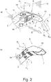
- the spout 2 comprises at its distal end a deflection mechanism 5 forming an outlet mouth 7 for the crop flow 3.
- the deflection mechanism 6 comprises an actuator arrangement 8 for adjusting at least part of the outlet mouth 7 in order to change the flow direction F 1 , F 2 of the crop flow 3 by deflection.
- the agricultural working machine 1 of the invention further comprises an operator assistance system 9 which controls the deflection mechanism 6. It is proposed that the deflection mechanism 6 is configured to be controlled by the operator assistance system 9 such that for distribution of the crops in the transport container 4 along the drive direction of the agricultural working machine 1 during a side-by-side transfer process of the agricultural working machine 1 and the transport container 5 the change in flow direction F 1 , F 2 may comprise a deflection component D D in drive direction D of the agricultural working machine 1.
- the deflection mechanism 6 is configured to be controlled by the operator assistance system 9 such that for distribution of the crops in the transport container 4 laterally to the drive direction of the agricultural working machine 1 the change in flow direction F 1 , F 2 may comprise a deflection component D L lateral to the drive direction of the agricultural working machine 1. If this is the case, a good distribution of the crops can be achieved in the transport container 4.
- the deflection component D D in the drive direction D can be realized in different ways.
- the actuator arrangement 8 of the deflection mechanism 6 adjusts at least part of the outlet mouth 7 sidewise with respect to a vertical plane V.
- the vertical plane V is preferably aligned with the crop flow 3 in the spout 2 prior entering the deflection mechanism 6. This is shown in Fig. 2 .
- the vertical plane V may be formed by a pivot axis P S of the spout 2 and the longitudinal extension of the spout 2. This can be seen in Fig. 1 .
- the actuator arrangement 8 of the deflection mechanism adjusts at least part of the outlet mouth 7 up or down with respect to horizontal plane H.
- the actuator 11, 13 respectively actuators 11, 13 of the actuator arrangement 8 may for example be hydraulic and/or pneumatic cylinders and/or hydraulic and/or electric motors.
- the actuator arrangement 8 of the deflection mechanism 6 adjusts at least part of the outlet mouth 7 both sidewise and up or down. Preferred designs of of the deflection mechanism 6 are shown in Fig. 2 and Fig. 3 .
- the deflection mechanism 6 of both embodiments comprises besides the actuator arrangement 8 a first deflection unit 10.
- the first deflection unit 10 can be adjusted by actuator 11 of the actuator arrangement 8.
- the deflection mechanism 6 comprises further a second deflection unit 12.
- This deflection unit 12 can be adjusted by an actuator 13.
- these two deflection units 10, 11 are arranged sequentially at the end of the spout 2. They are as described before adjustable by the actuator arrangement 8. In this way at least part of the outlet mouth 7 is adjustable in order to change the flow direction F 1 , F 2 of the crop flow 3 by deflection.
- the second deflection unit 12 is designed as spout flap. Also both deflection units may be substantially designed as spout flaps.
- the first deflection unit 10 is adjustable around a pivot axis P 1 by the actuator 11 and the second deflection unit 12 is adjustable around a pivot axis P 2 .
- the adjustment range of the first deflection unit 10 and/or of the second deflection unit 12 may be predefined.
- the pivot axis P 1 of the first deflection unit 10 and the pivot axis P 2 of the second deflection unit 12 are may be displaced to each other as shown in the embodiment of Fig. 2 .
- the deflection mechanism 6 comprises a, preferably only a, first deflection unit 10. It may be designed as spout flap. It is here and preferably adjustable by the actuator arrangement 8.
- the actuator arrangement 8 may comprise at least one or two actuators 11, 13.
- the first deflection unit 10 is adjustable around a first pivot axis P 1 and around a second pivot axis P 2 .
- the pivot axes P 1 and P 2 may cross each other, as shown in Fig. 3 .
- the distance of the pivot axes P 1 and P 2 may be preferably less then 30cm, preferably less then 10cm, further preferably less then 5cm. If the pivot axes P 1 , P 2 cross each other or are arranged close to each other the crop flow 3 can be better adjusted by the deflection mechanism 6.
- the angle between those two pivot axes P 1 , P 2 is preferably between 60 degrees and 120 degrees, further preferably between 75 degrees and 115 degrees, further preferably substantially 90 degrees.
- One pivot axis P 1 , P 2 of the deflection mechanism 6 may be substantially horizontal.
- a second pivot axis P 1 , P 2 may be substantially vertical.
- outlet mouth 7 of the deflection mechanism 6 is configured to be adjustable on a, preferably predetermined, curved track.
- the crop flow 3 is preferably guided by the outlet mouth 7 controlled by the operator assistance system 9 in an alternating manner around a center line, which center line C is preferably extending along the drive direction D of the agricultural working machine 1.
- the outlet mouth 7 is guided according to a filling strategy stored in the memory 9a of the operator assistance system 9.
- the previously described adjustments of the outlet mouth 7 are preferably at least partly, preferably automatically controlled by the operator assistance system 9 during the transfer process. It is also conceivable that the starting of the transfer process is triggered by an operator of the agricultural working machine 1 and/or the transport vehicle 2 and the transfer process is afterwards automatically controlled by the operator assistance system 9.
- the operator assistance system 9 preferably has a memory 9a and a processing unit 9b. Preferably in the memory 9a different filling strategies for at least the transport container are stored. Alternately or additionally known kinematics of the agricultural working machine 1 as well as the transport vehicle 5, especially the transport container 4, may be stored. Based on these the operator assistance system 9 may control the transfer process automatically using its processing unit 9b.
- the spout 2 is preferably pivotable, especially vertically and/or horizontally pivotable, and that the pivoting of the spout 2 is controllable by the operator assistance system 9 during the transfer process.
- the spout 2 may comprise one or more actuators for the pivoting.
- the agricultural working machine 1 may comprise a sensor arrangement 14 for detection of characteristic parameters of the transport vehicle 5.
- the sensor arrangement 14 may additionally detect characteristic parameters of the agricultural working machine 1 and/or especially characteristic parameters of the spout 2. These characteristic parameters can be for example the dimensions of the opening of the transport container 4 or the relative position of the crop flow or the outlet mouth 7 and the opening of the transport container 4. Further characteristic parameters are described in and it is referred to EP 2 020 174 B1 .
- the sensor arrangement 14 is as shown in Fig. 2 preferably mounted to the spout 2, especially to the deflection mechanism 6. It is arranged such that it focuses at least part of the opening of the transport container 4 during the transfer process.
- the sensor arrangement 14 may comprise or be a stereo camera and/or a photonic mixer device, preferably a time-of-flight sensor, and/or a panorama image camera and/or an infrared scanner and/or a laser scanner.
- the operator assistance system 9 controls the transfer process preferably automatically. Especially the operator assistance system 9 is configured to control the pivoting of the spout 2 and the adjustment of the outlet mouth 7 by the actuator arrangement 8 of the deflection mechanism 6 during the transfer process. This leads to better distributed crops in the transport containers 4 and may reduce the power demand respectively fuel consumption needed for performing the transfer process.
- the travel speed of the agricultural working machine 1 and/or the transport vehicle 5 is configured be controllable by the operator assistance system 9 during the transfer process as well.
- the operator assistance system 9 may be configured to synchronize the pivoting of the spout 2 and the adjustment of the outlet mouth 7 by the actuator arrangement 8 of the deflection mechanism 6 together with the travel speed of the agricultural working machine 1 and/or the transport vehicle 5.
- the transfer process can be further optimized especially regarding power demand respectively fuel consumption and distribution of the crops in the transport container.
- the operator assistance system 9 may control also the steering of the agricultural working machine 1 and/or the transport vehicle 5 and further synchronize the steering of the agricultural working machine 1 and/or the transport vehicle 5 with the pre-described synchronizations.
- the agricultural working machine 1 is a forage harvester it may comprise a cutting drum for processing of the crops and a downstream accelerator for accelerating the crops.
- the agricultural working machine 1 is a combine harvester comprising a trashing unit for trashing the harvested crops prior storing them into a crop tank.
- the agricultural working machine 1 may comprise a screw conveyer for transporting the crops through the spout 2.
Landscapes
- Life Sciences & Earth Sciences (AREA)
- Environmental Sciences (AREA)
- Fertilizing (AREA)
Applications Claiming Priority (1)
| Application Number | Priority Date | Filing Date | Title |
|---|---|---|---|
| DE102016118674 | 2016-09-30 |
Publications (2)
| Publication Number | Publication Date |
|---|---|
| EP3300582A1 true EP3300582A1 (fr) | 2018-04-04 |
| EP3300582B1 EP3300582B1 (fr) | 2019-10-09 |
Family
ID=59579471
Family Applications (1)
| Application Number | Title | Priority Date | Filing Date |
|---|---|---|---|
| EP17185491.2A Active EP3300582B1 (fr) | 2016-09-30 | 2017-08-09 | Machine de travail agricole |
Country Status (1)
| Country | Link |
|---|---|
| EP (1) | EP3300582B1 (fr) |
Cited By (3)
| Publication number | Priority date | Publication date | Assignee | Title |
|---|---|---|---|---|
| BE1026187B1 (de) * | 2018-02-15 | 2020-02-19 | Deere & Co | Auswurfanordnung zur Anbringung am Ende einer Austrageinrichtung |
| JP2020082902A (ja) * | 2018-11-20 | 2020-06-04 | 学校法人立命館 | 運搬機、作業機、運搬システム、運搬方法 |
| US11659788B2 (en) | 2019-12-31 | 2023-05-30 | Deere & Company | Vehicle automated unloading |
Citations (4)
| Publication number | Priority date | Publication date | Assignee | Title |
|---|---|---|---|---|
| EP1219153A2 (fr) * | 2000-12-23 | 2002-07-03 | CLAAS Selbstfahrende Erntemaschinen GmbH | Dispositif et méthode pour coordonner et contrôler des véhicules agricoles |
| DE102010004648A1 (de) | 2010-01-13 | 2011-07-14 | CLAAS Selbstfahrende Erntemaschinen GmbH, 33428 | Erntemaschine, insbesondere Feldhäcksler |
| EP2020174B1 (fr) | 2007-08-03 | 2012-02-29 | AGROCOM GmbH & Co. Agrarsystem KG | Machine de travail agricole |
| WO2015011237A2 (fr) * | 2013-07-24 | 2015-01-29 | Cnh Industrial Belgium Nv | Organe de commande d'appareil de déchargement destiné à des machines de récolte agricole |
-
2017
- 2017-08-09 EP EP17185491.2A patent/EP3300582B1/fr active Active
Patent Citations (4)
| Publication number | Priority date | Publication date | Assignee | Title |
|---|---|---|---|---|
| EP1219153A2 (fr) * | 2000-12-23 | 2002-07-03 | CLAAS Selbstfahrende Erntemaschinen GmbH | Dispositif et méthode pour coordonner et contrôler des véhicules agricoles |
| EP2020174B1 (fr) | 2007-08-03 | 2012-02-29 | AGROCOM GmbH & Co. Agrarsystem KG | Machine de travail agricole |
| DE102010004648A1 (de) | 2010-01-13 | 2011-07-14 | CLAAS Selbstfahrende Erntemaschinen GmbH, 33428 | Erntemaschine, insbesondere Feldhäcksler |
| WO2015011237A2 (fr) * | 2013-07-24 | 2015-01-29 | Cnh Industrial Belgium Nv | Organe de commande d'appareil de déchargement destiné à des machines de récolte agricole |
Cited By (4)
| Publication number | Priority date | Publication date | Assignee | Title |
|---|---|---|---|---|
| BE1026187B1 (de) * | 2018-02-15 | 2020-02-19 | Deere & Co | Auswurfanordnung zur Anbringung am Ende einer Austrageinrichtung |
| JP2020082902A (ja) * | 2018-11-20 | 2020-06-04 | 学校法人立命館 | 運搬機、作業機、運搬システム、運搬方法 |
| JP7209961B2 (ja) | 2018-11-20 | 2023-01-23 | 学校法人立命館 | 運搬機、収穫機、運搬システム、運搬方法 |
| US11659788B2 (en) | 2019-12-31 | 2023-05-30 | Deere & Company | Vehicle automated unloading |
Also Published As
| Publication number | Publication date |
|---|---|
| EP3300582B1 (fr) | 2019-10-09 |
Similar Documents
| Publication | Publication Date | Title |
|---|---|---|
| EP3300582B1 (fr) | Machine de travail agricole | |
| EP2510775B1 (fr) | Système et procédé de commande du transfert de récoltes | |
| EP2893797B1 (fr) | Dispositif de récolte | |
| EP2829171B1 (fr) | Moissonneuse automotrice et véhicule associé | |
| EP1393613B1 (fr) | Dispositif de contrôle pour une goulotte de transfert | |
| EP2100495B2 (fr) | Moissonneuse agricole dotée d'une goulotte de transbordement | |
| US9332692B2 (en) | Vehicle network, device and method for the coordination thereof | |
| EP2321206B1 (fr) | Dispositif de stockage intermédiaire et procédé pour son fonctionnement | |
| EP1685759B2 (fr) | Système pour l'alimentation uniforme des machines de travail | |
| DE102011121414A1 (de) | Verfahren und eine Vorrichtung zur Regelung einer Fahrt einer ersten selbstfahrenden Arbeitsmaschine in Bezug zu einer zweiten selbstfahrenden Arbeitsmaschine | |
| DE102012211001A1 (de) | Anordnung zur Kontrolle einer Austrageinrichtung einer Erntemaschine mit einer selbsttätigen Positionierung in einer Ruhestellung bei nicht möglichen bzw. stattfindendem Überladevorgang | |
| EP3210895A2 (fr) | Machine d'emballage par emboutissage | |
| EP2873315A1 (fr) | Machine de récolte | |
| EP2192061A2 (fr) | Dispositif de transfert, de stockage intermédiaire et de transmission de produits unitaires longitudinaux et cylindriques creux ainsi que procédé de fonctionnement d'un tel dispositif | |
| EP2564683B1 (fr) | Système de commande d'un dispositif de chargement | |
| EP3970471A1 (fr) | Procédé de commande de surcharge de cultures récoltées | |
| EP0992185A2 (fr) | Système automatique de direction à localisation ultrasonore | |
| BE1026568B1 (de) | Selbstfahrende erntemaschine mit einer überladeeinrichtung | |
| JP6202491B2 (ja) | 農作物排出装置及び走行型収穫機 | |
| JPH07194226A (ja) | コンバインの茎稈搬送装置 | |
| JPH07194233A (ja) | コンバインの制御装置 | |
| JPH07194227A (ja) | コンバインの茎稈搬送装置 | |
| JPH07194237A (ja) | コンバインの制御装置 | |
| JPH07194228A (ja) | コンバインの茎稈搬送装置 | |
| JPH07194232A (ja) | コンバインの制御装置 |
Legal Events
| Date | Code | Title | Description |
|---|---|---|---|
| PUAI | Public reference made under article 153(3) epc to a published international application that has entered the european phase |
Free format text: ORIGINAL CODE: 0009012 |
|
| STAA | Information on the status of an ep patent application or granted ep patent |
Free format text: STATUS: THE APPLICATION HAS BEEN PUBLISHED |
|
| AK | Designated contracting states |
Kind code of ref document: A1 Designated state(s): AL AT BE BG CH CY CZ DE DK EE ES FI FR GB GR HR HU IE IS IT LI LT LU LV MC MK MT NL NO PL PT RO RS SE SI SK SM TR |
|
| AX | Request for extension of the european patent |
Extension state: BA ME |
|
| STAA | Information on the status of an ep patent application or granted ep patent |
Free format text: STATUS: REQUEST FOR EXAMINATION WAS MADE |
|
| 17P | Request for examination filed |
Effective date: 20181004 |
|
| RBV | Designated contracting states (corrected) |
Designated state(s): AL AT BE BG CH CY CZ DE DK EE ES FI FR GB GR HR HU IE IS IT LI LT LU LV MC MK MT NL NO PL PT RO RS SE SI SK SM TR |
|
| STAA | Information on the status of an ep patent application or granted ep patent |
Free format text: STATUS: EXAMINATION IS IN PROGRESS |
|
| 17Q | First examination report despatched |
Effective date: 20181213 |
|
| GRAJ | Information related to disapproval of communication of intention to grant by the applicant or resumption of examination proceedings by the epo deleted |
Free format text: ORIGINAL CODE: EPIDOSDIGR1 |
|
| STAA | Information on the status of an ep patent application or granted ep patent |
Free format text: STATUS: GRANT OF PATENT IS INTENDED |
|
| GRAP | Despatch of communication of intention to grant a patent |
Free format text: ORIGINAL CODE: EPIDOSNIGR1 |
|
| INTG | Intention to grant announced |
Effective date: 20190528 |
|
| RAP1 | Party data changed (applicant data changed or rights of an application transferred) |
Owner name: CLAAS E-SYSTEMS GMBH |
|
| GRAS | Grant fee paid |
Free format text: ORIGINAL CODE: EPIDOSNIGR3 |
|
| GRAA | (expected) grant |
Free format text: ORIGINAL CODE: 0009210 |
|
| STAA | Information on the status of an ep patent application or granted ep patent |
Free format text: STATUS: THE PATENT HAS BEEN GRANTED |
|
| AK | Designated contracting states |
Kind code of ref document: B1 Designated state(s): AL AT BE BG CH CY CZ DE DK EE ES FI FR GB GR HR HU IE IS IT LI LT LU LV MC MK MT NL NO PL PT RO RS SE SI SK SM TR |
|
| REG | Reference to a national code |
Ref country code: GB Ref legal event code: FG4D |
|
| REG | Reference to a national code |
Ref country code: CH Ref legal event code: EP |
|
| REG | Reference to a national code |
Ref country code: IE Ref legal event code: FG4D |
|
| REG | Reference to a national code |
Ref country code: DE Ref legal event code: R096 Ref document number: 602017007595 Country of ref document: DE |
|
| REG | Reference to a national code |
Ref country code: AT Ref legal event code: REF Ref document number: 1187698 Country of ref document: AT Kind code of ref document: T Effective date: 20191115 |
|
| REG | Reference to a national code |
Ref country code: NL Ref legal event code: MP Effective date: 20191009 |
|
| REG | Reference to a national code |
Ref country code: LT Ref legal event code: MG4D |
|
| REG | Reference to a national code |
Ref country code: AT Ref legal event code: MK05 Ref document number: 1187698 Country of ref document: AT Kind code of ref document: T Effective date: 20191009 |
|
| PG25 | Lapsed in a contracting state [announced via postgrant information from national office to epo] |
Ref country code: NL Free format text: LAPSE BECAUSE OF FAILURE TO SUBMIT A TRANSLATION OF THE DESCRIPTION OR TO PAY THE FEE WITHIN THE PRESCRIBED TIME-LIMIT Effective date: 20191009 Ref country code: AT Free format text: LAPSE BECAUSE OF FAILURE TO SUBMIT A TRANSLATION OF THE DESCRIPTION OR TO PAY THE FEE WITHIN THE PRESCRIBED TIME-LIMIT Effective date: 20191009 Ref country code: SE Free format text: LAPSE BECAUSE OF FAILURE TO SUBMIT A TRANSLATION OF THE DESCRIPTION OR TO PAY THE FEE WITHIN THE PRESCRIBED TIME-LIMIT Effective date: 20191009 Ref country code: LV Free format text: LAPSE BECAUSE OF FAILURE TO SUBMIT A TRANSLATION OF THE DESCRIPTION OR TO PAY THE FEE WITHIN THE PRESCRIBED TIME-LIMIT Effective date: 20191009 Ref country code: LT Free format text: LAPSE BECAUSE OF FAILURE TO SUBMIT A TRANSLATION OF THE DESCRIPTION OR TO PAY THE FEE WITHIN THE PRESCRIBED TIME-LIMIT Effective date: 20191009 Ref country code: PT Free format text: LAPSE BECAUSE OF FAILURE TO SUBMIT A TRANSLATION OF THE DESCRIPTION OR TO PAY THE FEE WITHIN THE PRESCRIBED TIME-LIMIT Effective date: 20200210 Ref country code: ES Free format text: LAPSE BECAUSE OF FAILURE TO SUBMIT A TRANSLATION OF THE DESCRIPTION OR TO PAY THE FEE WITHIN THE PRESCRIBED TIME-LIMIT Effective date: 20191009 Ref country code: PL Free format text: LAPSE BECAUSE OF FAILURE TO SUBMIT A TRANSLATION OF THE DESCRIPTION OR TO PAY THE FEE WITHIN THE PRESCRIBED TIME-LIMIT Effective date: 20191009 Ref country code: NO Free format text: LAPSE BECAUSE OF FAILURE TO SUBMIT A TRANSLATION OF THE DESCRIPTION OR TO PAY THE FEE WITHIN THE PRESCRIBED TIME-LIMIT Effective date: 20200109 Ref country code: FI Free format text: LAPSE BECAUSE OF FAILURE TO SUBMIT A TRANSLATION OF THE DESCRIPTION OR TO PAY THE FEE WITHIN THE PRESCRIBED TIME-LIMIT Effective date: 20191009 Ref country code: BG Free format text: LAPSE BECAUSE OF FAILURE TO SUBMIT A TRANSLATION OF THE DESCRIPTION OR TO PAY THE FEE WITHIN THE PRESCRIBED TIME-LIMIT Effective date: 20200109 Ref country code: GR Free format text: LAPSE BECAUSE OF FAILURE TO SUBMIT A TRANSLATION OF THE DESCRIPTION OR TO PAY THE FEE WITHIN THE PRESCRIBED TIME-LIMIT Effective date: 20200110 |
|
| PG25 | Lapsed in a contracting state [announced via postgrant information from national office to epo] |
Ref country code: HR Free format text: LAPSE BECAUSE OF FAILURE TO SUBMIT A TRANSLATION OF THE DESCRIPTION OR TO PAY THE FEE WITHIN THE PRESCRIBED TIME-LIMIT Effective date: 20191009 Ref country code: RS Free format text: LAPSE BECAUSE OF FAILURE TO SUBMIT A TRANSLATION OF THE DESCRIPTION OR TO PAY THE FEE WITHIN THE PRESCRIBED TIME-LIMIT Effective date: 20191009 Ref country code: IS Free format text: LAPSE BECAUSE OF FAILURE TO SUBMIT A TRANSLATION OF THE DESCRIPTION OR TO PAY THE FEE WITHIN THE PRESCRIBED TIME-LIMIT Effective date: 20200224 |
|
| PG25 | Lapsed in a contracting state [announced via postgrant information from national office to epo] |
Ref country code: AL Free format text: LAPSE BECAUSE OF FAILURE TO SUBMIT A TRANSLATION OF THE DESCRIPTION OR TO PAY THE FEE WITHIN THE PRESCRIBED TIME-LIMIT Effective date: 20191009 |
|
| REG | Reference to a national code |
Ref country code: DE Ref legal event code: R097 Ref document number: 602017007595 Country of ref document: DE |
|
| PG2D | Information on lapse in contracting state deleted |
Ref country code: IS |
|
| PG25 | Lapsed in a contracting state [announced via postgrant information from national office to epo] |
Ref country code: CZ Free format text: LAPSE BECAUSE OF FAILURE TO SUBMIT A TRANSLATION OF THE DESCRIPTION OR TO PAY THE FEE WITHIN THE PRESCRIBED TIME-LIMIT Effective date: 20191009 Ref country code: RO Free format text: LAPSE BECAUSE OF FAILURE TO SUBMIT A TRANSLATION OF THE DESCRIPTION OR TO PAY THE FEE WITHIN THE PRESCRIBED TIME-LIMIT Effective date: 20191009 Ref country code: DK Free format text: LAPSE BECAUSE OF FAILURE TO SUBMIT A TRANSLATION OF THE DESCRIPTION OR TO PAY THE FEE WITHIN THE PRESCRIBED TIME-LIMIT Effective date: 20191009 Ref country code: EE Free format text: LAPSE BECAUSE OF FAILURE TO SUBMIT A TRANSLATION OF THE DESCRIPTION OR TO PAY THE FEE WITHIN THE PRESCRIBED TIME-LIMIT Effective date: 20191009 Ref country code: IS Free format text: LAPSE BECAUSE OF FAILURE TO SUBMIT A TRANSLATION OF THE DESCRIPTION OR TO PAY THE FEE WITHIN THE PRESCRIBED TIME-LIMIT Effective date: 20200209 |
|
| PLBE | No opposition filed within time limit |
Free format text: ORIGINAL CODE: 0009261 |
|
| STAA | Information on the status of an ep patent application or granted ep patent |
Free format text: STATUS: NO OPPOSITION FILED WITHIN TIME LIMIT |
|
| PG25 | Lapsed in a contracting state [announced via postgrant information from national office to epo] |
Ref country code: SK Free format text: LAPSE BECAUSE OF FAILURE TO SUBMIT A TRANSLATION OF THE DESCRIPTION OR TO PAY THE FEE WITHIN THE PRESCRIBED TIME-LIMIT Effective date: 20191009 Ref country code: SM Free format text: LAPSE BECAUSE OF FAILURE TO SUBMIT A TRANSLATION OF THE DESCRIPTION OR TO PAY THE FEE WITHIN THE PRESCRIBED TIME-LIMIT Effective date: 20191009 |
|
| 26N | No opposition filed |
Effective date: 20200710 |
|
| PG25 | Lapsed in a contracting state [announced via postgrant information from national office to epo] |
Ref country code: SI Free format text: LAPSE BECAUSE OF FAILURE TO SUBMIT A TRANSLATION OF THE DESCRIPTION OR TO PAY THE FEE WITHIN THE PRESCRIBED TIME-LIMIT Effective date: 20191009 |
|
| PG25 | Lapsed in a contracting state [announced via postgrant information from national office to epo] |
Ref country code: MC Free format text: LAPSE BECAUSE OF FAILURE TO SUBMIT A TRANSLATION OF THE DESCRIPTION OR TO PAY THE FEE WITHIN THE PRESCRIBED TIME-LIMIT Effective date: 20191009 |
|
| REG | Reference to a national code |
Ref country code: CH Ref legal event code: PL |
|
| PG25 | Lapsed in a contracting state [announced via postgrant information from national office to epo] |
Ref country code: LU Free format text: LAPSE BECAUSE OF NON-PAYMENT OF DUE FEES Effective date: 20200809 Ref country code: LI Free format text: LAPSE BECAUSE OF NON-PAYMENT OF DUE FEES Effective date: 20200831 Ref country code: CH Free format text: LAPSE BECAUSE OF NON-PAYMENT OF DUE FEES Effective date: 20200831 |
|
| PG25 | Lapsed in a contracting state [announced via postgrant information from national office to epo] |
Ref country code: IE Free format text: LAPSE BECAUSE OF NON-PAYMENT OF DUE FEES Effective date: 20200809 |
|
| GBPC | Gb: european patent ceased through non-payment of renewal fee |
Effective date: 20210809 |
|
| PG25 | Lapsed in a contracting state [announced via postgrant information from national office to epo] |
Ref country code: TR Free format text: LAPSE BECAUSE OF FAILURE TO SUBMIT A TRANSLATION OF THE DESCRIPTION OR TO PAY THE FEE WITHIN THE PRESCRIBED TIME-LIMIT Effective date: 20191009 Ref country code: MT Free format text: LAPSE BECAUSE OF FAILURE TO SUBMIT A TRANSLATION OF THE DESCRIPTION OR TO PAY THE FEE WITHIN THE PRESCRIBED TIME-LIMIT Effective date: 20191009 Ref country code: CY Free format text: LAPSE BECAUSE OF FAILURE TO SUBMIT A TRANSLATION OF THE DESCRIPTION OR TO PAY THE FEE WITHIN THE PRESCRIBED TIME-LIMIT Effective date: 20191009 |
|
| PG25 | Lapsed in a contracting state [announced via postgrant information from national office to epo] |
Ref country code: MK Free format text: LAPSE BECAUSE OF FAILURE TO SUBMIT A TRANSLATION OF THE DESCRIPTION OR TO PAY THE FEE WITHIN THE PRESCRIBED TIME-LIMIT Effective date: 20191009 |
|
| PG25 | Lapsed in a contracting state [announced via postgrant information from national office to epo] |
Ref country code: GB Free format text: LAPSE BECAUSE OF NON-PAYMENT OF DUE FEES Effective date: 20210809 |
|
| P01 | Opt-out of the competence of the unified patent court (upc) registered |
Effective date: 20230516 |
|
| PGFP | Annual fee paid to national office [announced via postgrant information from national office to epo] |
Ref country code: IT Payment date: 20230825 Year of fee payment: 7 |
|
| PGFP | Annual fee paid to national office [announced via postgrant information from national office to epo] |
Ref country code: FR Payment date: 20230825 Year of fee payment: 7 Ref country code: DE Payment date: 20230821 Year of fee payment: 7 Ref country code: BE Payment date: 20230821 Year of fee payment: 7 |