EP2959032B1 - Dekorative, tiefschwarze beschichtung - Google Patents
Dekorative, tiefschwarze beschichtung Download PDFInfo
- Publication number
- EP2959032B1 EP2959032B1 EP14705280.7A EP14705280A EP2959032B1 EP 2959032 B1 EP2959032 B1 EP 2959032B1 EP 14705280 A EP14705280 A EP 14705280A EP 2959032 B1 EP2959032 B1 EP 2959032B1
- Authority
- EP
- European Patent Office
- Prior art keywords
- layer
- gradient
- dlc
- refractive index
- hard material
- Prior art date
- Legal status (The legal status is an assumption and is not a legal conclusion. Google has not performed a legal analysis and makes no representation as to the accuracy of the status listed.)
- Active
Links
Images
Classifications
-
- C—CHEMISTRY; METALLURGY
- C23—COATING METALLIC MATERIAL; COATING MATERIAL WITH METALLIC MATERIAL; CHEMICAL SURFACE TREATMENT; DIFFUSION TREATMENT OF METALLIC MATERIAL; COATING BY VACUUM EVAPORATION, BY SPUTTERING, BY ION IMPLANTATION OR BY CHEMICAL VAPOUR DEPOSITION, IN GENERAL; INHIBITING CORROSION OF METALLIC MATERIAL OR INCRUSTATION IN GENERAL
- C23C—COATING METALLIC MATERIAL; COATING MATERIAL WITH METALLIC MATERIAL; SURFACE TREATMENT OF METALLIC MATERIAL BY DIFFUSION INTO THE SURFACE, BY CHEMICAL CONVERSION OR SUBSTITUTION; COATING BY VACUUM EVAPORATION, BY SPUTTERING, BY ION IMPLANTATION OR BY CHEMICAL VAPOUR DEPOSITION, IN GENERAL
- C23C28/00—Coating for obtaining at least two superposed coatings either by methods not provided for in a single one of groups C23C2/00 - C23C26/00 or by combinations of methods provided for in subclasses C23C and C25C or C25D
- C23C28/04—Coating for obtaining at least two superposed coatings either by methods not provided for in a single one of groups C23C2/00 - C23C26/00 or by combinations of methods provided for in subclasses C23C and C25C or C25D only coatings of inorganic non-metallic material
- C23C28/048—Coating for obtaining at least two superposed coatings either by methods not provided for in a single one of groups C23C2/00 - C23C26/00 or by combinations of methods provided for in subclasses C23C and C25C or C25D only coatings of inorganic non-metallic material with layers graded in composition or physical properties
-
- C—CHEMISTRY; METALLURGY
- C23—COATING METALLIC MATERIAL; COATING MATERIAL WITH METALLIC MATERIAL; CHEMICAL SURFACE TREATMENT; DIFFUSION TREATMENT OF METALLIC MATERIAL; COATING BY VACUUM EVAPORATION, BY SPUTTERING, BY ION IMPLANTATION OR BY CHEMICAL VAPOUR DEPOSITION, IN GENERAL; INHIBITING CORROSION OF METALLIC MATERIAL OR INCRUSTATION IN GENERAL
- C23C—COATING METALLIC MATERIAL; COATING MATERIAL WITH METALLIC MATERIAL; SURFACE TREATMENT OF METALLIC MATERIAL BY DIFFUSION INTO THE SURFACE, BY CHEMICAL CONVERSION OR SUBSTITUTION; COATING BY VACUUM EVAPORATION, BY SPUTTERING, BY ION IMPLANTATION OR BY CHEMICAL VAPOUR DEPOSITION, IN GENERAL
- C23C16/00—Chemical coating by decomposition of gaseous compounds, without leaving reaction products of surface material in the coating, i.e. chemical vapour deposition [CVD] processes
- C23C16/006—Chemical coating by decomposition of gaseous compounds, without leaving reaction products of surface material in the coating, i.e. chemical vapour deposition [CVD] processes characterized by the colour of the layer
-
- C—CHEMISTRY; METALLURGY
- C23—COATING METALLIC MATERIAL; COATING MATERIAL WITH METALLIC MATERIAL; CHEMICAL SURFACE TREATMENT; DIFFUSION TREATMENT OF METALLIC MATERIAL; COATING BY VACUUM EVAPORATION, BY SPUTTERING, BY ION IMPLANTATION OR BY CHEMICAL VAPOUR DEPOSITION, IN GENERAL; INHIBITING CORROSION OF METALLIC MATERIAL OR INCRUSTATION IN GENERAL
- C23C—COATING METALLIC MATERIAL; COATING MATERIAL WITH METALLIC MATERIAL; SURFACE TREATMENT OF METALLIC MATERIAL BY DIFFUSION INTO THE SURFACE, BY CHEMICAL CONVERSION OR SUBSTITUTION; COATING BY VACUUM EVAPORATION, BY SPUTTERING, BY ION IMPLANTATION OR BY CHEMICAL VAPOUR DEPOSITION, IN GENERAL
- C23C14/00—Coating by vacuum evaporation, by sputtering or by ion implantation of the coating forming material
- C23C14/22—Coating by vacuum evaporation, by sputtering or by ion implantation of the coating forming material characterised by the process of coating
- C23C14/34—Sputtering
- C23C14/3435—Applying energy to the substrate during sputtering
- C23C14/345—Applying energy to the substrate during sputtering using substrate bias
-
- C—CHEMISTRY; METALLURGY
- C23—COATING METALLIC MATERIAL; COATING MATERIAL WITH METALLIC MATERIAL; CHEMICAL SURFACE TREATMENT; DIFFUSION TREATMENT OF METALLIC MATERIAL; COATING BY VACUUM EVAPORATION, BY SPUTTERING, BY ION IMPLANTATION OR BY CHEMICAL VAPOUR DEPOSITION, IN GENERAL; INHIBITING CORROSION OF METALLIC MATERIAL OR INCRUSTATION IN GENERAL
- C23C—COATING METALLIC MATERIAL; COATING MATERIAL WITH METALLIC MATERIAL; SURFACE TREATMENT OF METALLIC MATERIAL BY DIFFUSION INTO THE SURFACE, BY CHEMICAL CONVERSION OR SUBSTITUTION; COATING BY VACUUM EVAPORATION, BY SPUTTERING, BY ION IMPLANTATION OR BY CHEMICAL VAPOUR DEPOSITION, IN GENERAL
- C23C16/00—Chemical coating by decomposition of gaseous compounds, without leaving reaction products of surface material in the coating, i.e. chemical vapour deposition [CVD] processes
- C23C16/02—Pretreatment of the material to be coated
- C23C16/0272—Deposition of sub-layers, e.g. to promote the adhesion of the main coating
-
- C—CHEMISTRY; METALLURGY
- C23—COATING METALLIC MATERIAL; COATING MATERIAL WITH METALLIC MATERIAL; CHEMICAL SURFACE TREATMENT; DIFFUSION TREATMENT OF METALLIC MATERIAL; COATING BY VACUUM EVAPORATION, BY SPUTTERING, BY ION IMPLANTATION OR BY CHEMICAL VAPOUR DEPOSITION, IN GENERAL; INHIBITING CORROSION OF METALLIC MATERIAL OR INCRUSTATION IN GENERAL
- C23C—COATING METALLIC MATERIAL; COATING MATERIAL WITH METALLIC MATERIAL; SURFACE TREATMENT OF METALLIC MATERIAL BY DIFFUSION INTO THE SURFACE, BY CHEMICAL CONVERSION OR SUBSTITUTION; COATING BY VACUUM EVAPORATION, BY SPUTTERING, BY ION IMPLANTATION OR BY CHEMICAL VAPOUR DEPOSITION, IN GENERAL
- C23C16/00—Chemical coating by decomposition of gaseous compounds, without leaving reaction products of surface material in the coating, i.e. chemical vapour deposition [CVD] processes
- C23C16/22—Chemical coating by decomposition of gaseous compounds, without leaving reaction products of surface material in the coating, i.e. chemical vapour deposition [CVD] processes characterised by the deposition of inorganic material, other than metallic material
- C23C16/26—Deposition of carbon only
-
- C—CHEMISTRY; METALLURGY
- C23—COATING METALLIC MATERIAL; COATING MATERIAL WITH METALLIC MATERIAL; CHEMICAL SURFACE TREATMENT; DIFFUSION TREATMENT OF METALLIC MATERIAL; COATING BY VACUUM EVAPORATION, BY SPUTTERING, BY ION IMPLANTATION OR BY CHEMICAL VAPOUR DEPOSITION, IN GENERAL; INHIBITING CORROSION OF METALLIC MATERIAL OR INCRUSTATION IN GENERAL
- C23C—COATING METALLIC MATERIAL; COATING MATERIAL WITH METALLIC MATERIAL; SURFACE TREATMENT OF METALLIC MATERIAL BY DIFFUSION INTO THE SURFACE, BY CHEMICAL CONVERSION OR SUBSTITUTION; COATING BY VACUUM EVAPORATION, BY SPUTTERING, BY ION IMPLANTATION OR BY CHEMICAL VAPOUR DEPOSITION, IN GENERAL
- C23C16/00—Chemical coating by decomposition of gaseous compounds, without leaving reaction products of surface material in the coating, i.e. chemical vapour deposition [CVD] processes
- C23C16/44—Chemical coating by decomposition of gaseous compounds, without leaving reaction products of surface material in the coating, i.e. chemical vapour deposition [CVD] processes characterised by the method of coating
- C23C16/455—Chemical coating by decomposition of gaseous compounds, without leaving reaction products of surface material in the coating, i.e. chemical vapour deposition [CVD] processes characterised by the method of coating characterised by the method used for introducing gases into reaction chamber or for modifying gas flows in reaction chamber
- C23C16/45523—Pulsed gas flow or change of composition over time
-
- C—CHEMISTRY; METALLURGY
- C23—COATING METALLIC MATERIAL; COATING MATERIAL WITH METALLIC MATERIAL; CHEMICAL SURFACE TREATMENT; DIFFUSION TREATMENT OF METALLIC MATERIAL; COATING BY VACUUM EVAPORATION, BY SPUTTERING, BY ION IMPLANTATION OR BY CHEMICAL VAPOUR DEPOSITION, IN GENERAL; INHIBITING CORROSION OF METALLIC MATERIAL OR INCRUSTATION IN GENERAL
- C23C—COATING METALLIC MATERIAL; COATING MATERIAL WITH METALLIC MATERIAL; SURFACE TREATMENT OF METALLIC MATERIAL BY DIFFUSION INTO THE SURFACE, BY CHEMICAL CONVERSION OR SUBSTITUTION; COATING BY VACUUM EVAPORATION, BY SPUTTERING, BY ION IMPLANTATION OR BY CHEMICAL VAPOUR DEPOSITION, IN GENERAL
- C23C16/00—Chemical coating by decomposition of gaseous compounds, without leaving reaction products of surface material in the coating, i.e. chemical vapour deposition [CVD] processes
- C23C16/44—Chemical coating by decomposition of gaseous compounds, without leaving reaction products of surface material in the coating, i.e. chemical vapour deposition [CVD] processes characterised by the method of coating
- C23C16/50—Chemical coating by decomposition of gaseous compounds, without leaving reaction products of surface material in the coating, i.e. chemical vapour deposition [CVD] processes characterised by the method of coating using electric discharges
- C23C16/513—Chemical coating by decomposition of gaseous compounds, without leaving reaction products of surface material in the coating, i.e. chemical vapour deposition [CVD] processes characterised by the method of coating using electric discharges using plasma jets
-
- C—CHEMISTRY; METALLURGY
- C23—COATING METALLIC MATERIAL; COATING MATERIAL WITH METALLIC MATERIAL; CHEMICAL SURFACE TREATMENT; DIFFUSION TREATMENT OF METALLIC MATERIAL; COATING BY VACUUM EVAPORATION, BY SPUTTERING, BY ION IMPLANTATION OR BY CHEMICAL VAPOUR DEPOSITION, IN GENERAL; INHIBITING CORROSION OF METALLIC MATERIAL OR INCRUSTATION IN GENERAL
- C23C—COATING METALLIC MATERIAL; COATING MATERIAL WITH METALLIC MATERIAL; SURFACE TREATMENT OF METALLIC MATERIAL BY DIFFUSION INTO THE SURFACE, BY CHEMICAL CONVERSION OR SUBSTITUTION; COATING BY VACUUM EVAPORATION, BY SPUTTERING, BY ION IMPLANTATION OR BY CHEMICAL VAPOUR DEPOSITION, IN GENERAL
- C23C28/00—Coating for obtaining at least two superposed coatings either by methods not provided for in a single one of groups C23C2/00 - C23C26/00 or by combinations of methods provided for in subclasses C23C and C25C or C25D
- C23C28/04—Coating for obtaining at least two superposed coatings either by methods not provided for in a single one of groups C23C2/00 - C23C26/00 or by combinations of methods provided for in subclasses C23C and C25C or C25D only coatings of inorganic non-metallic material
- C23C28/046—Coating for obtaining at least two superposed coatings either by methods not provided for in a single one of groups C23C2/00 - C23C26/00 or by combinations of methods provided for in subclasses C23C and C25C or C25D only coatings of inorganic non-metallic material with at least one amorphous inorganic material layer, e.g. DLC, a-C:H, a-C:Me, the layer being doped or not
Definitions
- the present invention relates to a method for producing a wear protection layer for decorative applications with a deep black appearance.
- black appearing surfaces for example in the field of consumer goods such as watch cases, mobile phones or bumpers on motor vehicles.
- not only the outer, preferably deep black appearance plays a role, but also the resistance to external mechanical effects.
- the surface should be scratch resistant.
- This hard material layer comprises a first layer consisting of an element of groups IVa, Va of the periodic table of elements, a second layer comprising a nitride of this element of the first layer, a third layer comprising a carbide of the element and a cover layer consisting of a hard carbon layer, wherein carbide crystallites of the same element are embedded in this cover layer.
- DLC layers have a black appearance and a high degree of hardness.
- L * lightness
- the gradient is realized so that the total hardness of the layer is not less than 15 GPa.
- the DLC layer has a refractive index between 2 and 3 and / or a neutral gray value L * between 40 and 60, more preferably between 45 and 55.
- the DLC layer has a hardness not lower than 1500HV or 15GPa, preferably not lower than 18GPa, and more preferably not lower than 20GPa. is.
- the gradient layer thickness there is no region having hardness lower than 600 HV or 6 GPa, preferably not lower than 8 GPa.
- the thickness of the DLC layer is not less than 0.5 ⁇ m.
- the thickness of the gradient layer is not less than 300 nm.
- a coating according to the present invention may be prepared by plasma assisted CVD processes or PVD processes, or a combination of both.
- a preferred embodiment of the present invention for making the layers comprises a combined plasma assisted CVD and sputtering process.
- the substrates were fabricated in a vacuum chamber by a plasma assisted CVD method using a combination of acetylene and argon as the process gas.
- the process gas was ionized in the chamber by means of a plasma generated via a low-voltage arc discharge.
- a substrate bias was applied to the substrates during the coating process.
- the substrate bias was maintained at a constant value of 900V.
- the DLC coating took 80 minutes.
- the substrate bias was continuously 900 V reduced to 50V. After 40 minutes, a substrate bias of 50 V was achieved.
- the other coating parameters were kept constant throughout the coating.
- the low-voltage arc discharge current is continuously increased in order to counteract the decrease in the substrate current associated with the reduction of the substrate bias. This continuous reduction of the substrate bias resulted in a continuous reduction of the layer density, which in turn resulted in a reduction of the refractive index.
- the gradient layer was 0.7 ⁇ m thick.
- the hardness measured for the overall system (DLC layer and gradient layer) on a 10mN load fishing scope was 18GPa.
- the green-red factor a * and the yellow-blue factor b * were measured according to the definition of the Lab color space. For a * a value of -0.5 ⁇ 1 and for b * a value of 1 ⁇ 1 was measured.
- the layer system showed excellent wear resistance.
- the refractive index of the gradient layer can not be arbitrarily reduced, because this has a direct influence on the total hardness of the layer.
- the reflection-reducing effect of the gradient layer is not based on interference effects, it is possible once the lowest refractive index to be realized has been reached to further coat the gradient layer with this refractive index.
- a substrate bias of 50 V upon reaching a substrate bias of 50 V, it would be possible to further coat for 20 minutes while maintaining this bias value, without increasing the reflection again.
- a depth profile of the hydrogen atom concentration ([H]) was determined using 2 MeV He ERDA (Elastic Recoil Detection Analysis) for 2 DLC samples: one with and one without gradient.
- a standard with 9.5 at% H (mica) as reference was measured and the energy loss (braking power) of the alpha particles in the DLC layers and in the standard was determined using the SRIM program ( www.srim.org ).
- the coating of the DLC layer without gradient took place with a constant substrate bias of 900 V and took 80 minutes (layer thickness ⁇ 1 ⁇ m).
- the substrate bias was continuously reduced from 900V to 50V. This step took 80 minutes and resulted in a gradient layer thickness of 1.5 ⁇ m.
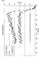
- FIG. 1 The results are in FIG. 1 shown. This method allows to measure to a depth of about 350 nm. The surface is in profile to the right (0) and the depth scale runs to the left. The results show that the hydrogen atom concentration increases towards the gradient surface. For the DLC sample without gradient, however, the hydrogen atom atom concentration remains constant.
- the wear resistance of the gradient layer DLC sample was evaluated by an application-based test method based on James Heal's "Crockmaster" abrasion tester ( http://www.james-heal.co.uk/ ).
- a coated sample was rubbed with a 1 cm x 1 cm sandpaper (3M281Q Wetordry, with 9 ⁇ m Al2O3 particles).
- the machine moves the sandpaper back and forth on the deep black DLC coated sample at a frequency of 1 Hz.
- a 9N load is placed on the sandpaper and this is replaced after every 500 reciprocating cycles. After 6,000 strokes no significant change in color values (L *, a * and b *) and no scratches were observed.
- deep black (L * 35) TiAlCN PVD layers under the same test conditions after 1000 Hubzykien considerable abrasion.
Landscapes
- Chemical & Material Sciences (AREA)
- Engineering & Computer Science (AREA)
- Metallurgy (AREA)
- Chemical Kinetics & Catalysis (AREA)
- Materials Engineering (AREA)
- Mechanical Engineering (AREA)
- Organic Chemistry (AREA)
- General Chemical & Material Sciences (AREA)
- Inorganic Chemistry (AREA)
- Physics & Mathematics (AREA)
- Plasma & Fusion (AREA)
- Chemical Vapour Deposition (AREA)
- Laminated Bodies (AREA)
- Carbon And Carbon Compounds (AREA)
Description
- Die vorliegende Erfindung bezieht sich auf eine Methode zu Herstellung einer Verschleissschutzschicht für dekorative Anwendungen mit tiefschwarzem Aussehen. Es besteht ein grosses Bedürfnis nach schwarz erscheinenden Oberflächen, so zum Beispiel im Bereich von Konsumartikeln wie Uhrengehäuse, Mobiltelefone oder auch Stossstangen an Kraftfahrzeugen. Bei solchen Anwendungen spielt jedoch nicht nur das äussere, vorzugsweise tiefschwarze Erscheinungsbild eine Rolle, sondern auch die Beständigkeit gegenüber äusseren mechanische Einwirkungen. Insbesondere sollte die Oberfläche kratzfest sein.
- In der deutschen Anmeldung
DE3639469 wird eine Hartstoffschicht mit dekorativem schwarzen Erscheinungsbild beschrieben, die gleichzeitig eine hohe Verschleissbeständigkeit aufweist. Diese Hartstoffschicht umfasst eine erste Schicht bestehend aus einem Element der Gruppen IVa, Va des periodischen Systems der Elemente, eine zweite Schicht, welche ein Nitrid dieses Elementes der ersten Schicht umfasst, eine dritte Schicht, welche ein Karbid des Elementes umfasst und eine Deckschicht bestehend aus einer harten Kohlenstoffschicht, wobei Karbidkristallite desselben Elementes in diese Deckschicht eingebettet sind. - Es ist ausserdem bekannt, DLC-Schichten einzusetzen. Diese haben ein schwarzes Erscheinungsbild und einen hohen Härtegrad. Allerdings besitzen herkömmliche DLC-Schichten Neutralgrauwerte (L* =lightness), welche im Bereich über 40 liegen. Hierbei und im Rahmen der vorliegenden Beschreibung wird der CIE 1976 L*a*b* Farbraum auf der Basis einer D65 Standardbeleuchtung und einer d/8° (=diffuse Beleuchtung und Messung unter 8°) zugrunde gelegt. Als tiefschwarze Oberflächen werden im Zusammenhang mit der vorliegenden Beschreibung Oberflächen bezeichnet, die Neutralgrauwerte L*=<40 aufweisen.
- Der schwarze Eindruck der DLC-Schichten erfolgt durch ihre gute Absorptionsfähigkeit. Dies ist eine Folge des relativ hohen Absorptionskoeffizienten des Materials. Dieser Absorptionskoeffizient geht allerdings mit einem hohen Brechungsindex von zwischen 2.1 und 2.3 einher. Dies hat zur Folge, dass beim Auftreffen des Lichtes auf die Oberfläche der DLC-Beschichtung aufgrund des grossen Sprungs im Brechungsindex beim Übergang von Luft (n=1) in die Schicht ein signifikanter Teil des Lichtes reflektiert wird und so zu einem hohen L* Wert führt. Es wäre nun möglich, auf dieser Oberfläche eine optische Antireflexionsschicht vorzusehen. Allerdings basieren solche Schichten auf dem Prinzip der Interferenz. Deren Reflexionsverhalten ist somit einerseits wellenlängenabhängig und andererseits auch abhängig vom Einfallswinkel. Es kommt hinzu, dass das Reflexionsverhalten solcher Schichten stark von der realisierten Schichtdicke abhängig ist. Dies kann vor allem bei Geometrien der zu beschichtenden Bauteite, welche nicht planar sind,zu erheblichen Problemen führen.
- Es besteht daher ein Bedürfnis nach einer harten Oberflächenbeschichtung, welche zu einem tiefschwarzen optischen Eindruck führt, der vorzugsweise unabhängig vom Betrachtungswinkel bestehen bleibt.
- Es ist daher die Aufgabe der vorliegenden Erfindung, eine harte Oberflächenbeschichtung anzugeben, welche zu einem tiefschwarzen optischen Eindruck führt, der vorzugsweise unabhängig vom Betrachtungswinkel bestehen bleibt.
- Das entsprechend der vorliegenden Erfindung hergestellte Schichtsystem zeigt einen niedrigeren L* Wert als eine herkömmliche DLC-Schicht. Dies wird dadurch erreicht, dass auf eine DLC-Schicht eine Gradientenschicht mit abnehmender Dichte und dadurch mit abnehmendem Brechungsindex realisiert wird. Bei genügender Dicke der Gradientenschicht wird hierdurch eine Verminderung der Fresnelreflexion an der Oberfläche erreicht. Beispielsweise beträgt die Reflexion einer herkömmlichen DLC-Oberfläche mit nDLC=2.3 bei senkrechtem Lichteinfall ca 16%. Dies führt zu einem L*-Wert von ca. 47. Demgegenüber beträgt die Reflexion einer Oberfläche mit n=1.7 bei senkrechtem Lichteinfall lediglich 7%. Aufgrund des in der Gradientenschicht realisierten ansteigenden Brechungsindexes kommt es innerhalb der Gradientenschicht und beim Übergang zur DLC-Schicht im Wesentlichen nicht mehr zur Fresnelreflexion. Damit liegt der L* bei lediglich 32.
- Dabei ist klar, dass aufgrund der geringeren und abnehmenden Dichte der Gradientenschicht dies zu einer Reduktion der Gesamthärte der Schicht führt. In einer bevorzugten Ausführungsform wird der Gradient so realisiert, dass die Gesamthärte der Schicht nicht geringer als 15 GPa ist.
- Gemäss einer weiteren bevorzugten Ausführungsform der vorliegenden Erfindung hat die DLC-Schicht einen Brechungsindex zwischen 2 und 3 und/oder einen Neutralgrauwert L* zwischen 40 und 60, mehr bevorzugt zwischen 45 und 55.
- Gemäss einer weiteren bevorzugten Ausführungsform der vorliegenden Erfindung hat die DLC-Schicht eine Härte, welche nicht geringer als 1500HV oder 15 GPa ist, bevorzugterweise nicht geringer als 18 GPa ist und noch bevorzugter nicht geringer als 20 GPa. ist.
- Gemäss einer weiteren bevorzugten Ausführungsform der vorliegenden Erfindung gibt es innerhalb der Gradientenschichtdicke keinen Bereich,der eine geringere Härte als 600 HV oder 6 GPa aufweist, vorzugsweise nicht geringer als 8 GPa.
- Gemäss einer weiteren Ausführungsform der vorliegenden Erfindung ist die Dicke der DLC-Schicht nicht geringer als 0.5µm.
- Gemäss einer weiteren Ausführungsform der vorliegenden Erfindung beträgt die Dicke der Gradientenschicht nicht weniger als 300 nm.
- Eine Beschichtung gemäss der vorliegenden Erfindung kann beispielsweise mittels Plasma-unterstützten CVD Prozessen oder PVD - Prozessen oder einer Kombination aus beidem hergestellt werden.
- Eine bevorzugte Ausführungsform der vorliegenden Erfindung zur Herstellung der Schichten umfasst einen kombinierten plasmaunterstützten CVD und Zerstäubungsprozess.
- Die Beschichtung entsprechend der vorliegenden Erfindung hat unter anderem folgende Vorteile:
- Die DLC-Schicht bleibt hart genug,um Verschleissschutz zu gewährleisten. Falls die etwas weichere Gradientenschicht Kratzer bekommt, bleibt wenigstens die darunter liegende DLC-Schicht intakt und da diese auch schwarz ist, wird der Kratzer kaum auffallen.
- Auf Substraten mit erhöhter Rauigkeit kann es sogar zu einer Erhöhung der Verschleissbeständigkeit der Gradientenschicht kommen, da die Bereiche zwischen den Substratspitzen geschützt sind.
- Dadurch, dass der Effekt der Reflexminderung nicht auf Interferenzeffekte zurückgeht, sind die Schichtdickenabhängigkeit und die Winkelabhängigkeit der Reflexion stark vermindert.
- Zur Herstellung der Gradientenschicht können herkömmliche Anlagen für die Herstellung der DLC-Schicht herangezogen werden. Es wird keine zusätzliche Ausrüstung oder zusätzliche Gase benötigt.
- Die Erfindung wird nun anhand einer Prozessbeschreibung im Detail und beispielhaft erläutert :
-
Figur 1 zeigt die Wasserstoffkonzentration für verschiedene DLC Proben im Vergleich zu einer Referenz. - Die Substrate wurden in einer Vakuumkammer mittels einer plasmaunterstützten CVD Methode hergestellt, wobei eine Kombination aus Acetylen und Argon als Prozessgas verwendet wird. Das Prozessgas wurde in der Kammer mittels eines Plasmas ionisiert, welches über eine Niedervoltbogenentladung erzeugt wurde. Zusätzlich wurde während des Beschichtungsprozesses ein Substratbias an die Substrate angelegt.
- Zur Beschichtung der DLC-Schicht wurde der Substratbias auf einem konstanten Wert von 900 V gehalten. Die DLC-Beschichtung nahm 80 Minuten in Anspruch. Zur Beschichtung der Gradientenschicht wurde der Substratbias kontinuierlich von 900 V auf 50 V reduziert. Nach Ablauf von 40 Minuten war ein Substratbias von 50 V erreicht. Abgesehen vom Substratbias wurden die anderen Beschichtungsparameter während der gesamten Beschichtung konstant gehalten. Vorzugsweise wird jedoch der Niedervoltbogen-Entladungsstrom kontinuierlich erhöht um der mit der Reduktion des Substratbias einhergehenden Abnahme des Substratstroms entgegen zu wirken. Durch diese kontinuierliche Reduktion des Substratbias erfolgte eine kontinuierliche Reduktion der Schichtdichte, die wiederum eine Reduktion des Brechungsindexes zur Folge hatte.
- Im Ergebnis war die Gradientenschicht 0.7 µm dick. Die für das Gesamtsystem (DLC-Schicht und Gradientenschicht) auf einem Fischerscope mit 10mN Last gemessene Härte betrug 18GPa. Der gemessene Wert L* betrug 35. Dies würde einem Brechungsindex an der Oberfläche von n = 1.85 entsprechen. Zusätzlich wurde der grün-rot Faktor a* und der gelb-blau Faktor b* entsprechend der Definition des Lab Farbraums gemessen. Für a* wurde ein Wert von -0.5±1 und für b* wurde ein Wert von 1±1 gemessen. Das Schichtsystem zeigte eine exzellente Verschleissbeständigkeit.
- Der Brechungsindex der Gradientenschicht kann nicht beliebig reduziert werden, weil dies unmittelbar Einfluss auf die Gesamthärte der Schicht hat. Dadurch allerdings, dass der reflexmindernde Effekt der Gradientenschicht nicht auf Interferenzeffekten beruht, ist es möglich, wenn einmal der niedrigste zu realisierende Brechungsindex erreicht ist, die Gradientenschicht mit diesem Brechungsindex weiter zu beschichten. Im vorangehenden Beispiel könnte man zum Beispiel bei Erreichen eines Substratbias von 50 V für 20 Minuten unter Beibehaltung dieses Biaswertes weiterbeschichten, ohne die Reflexion wieder zu erhöhen.
- Das in der Beschreibung aufgezeigte Beispiel bezog sich auf eine Gradientenschicht, welche in ihrer Zusammensetzung im Wesentlichen der DLC-Schicht entspricht. Es ist jedoch auch möglich, eine geringere optische Dichte dadurch zu erzielen, dass nach Aufbringen der DLC-Schicht im weiteren Beschichtungsverlauf und mit zunehmender Konzentration ein weiteres chemisches Element oder mehrere weitere chemische Elemente beigefügt werden, während gleichzeitig die Konzentration des Kohlenstoffs abnimmt. Im Extremfall kann der Kohlenstoffgehalt an der Oberfläche Null betragen. Beispielhaft sei hier Silizium bzw. SiOx erwähnt mit x>=0. Wird zum Beispiel so vorgegangen, dass es, ausgehend von der DLC-Schicht, zu einer Zunahme des SiOx Gehaltes kommt, eventuell auch mit Variation von x, beispielsweise von x=0 an der "Grenzfläche" zur DLC-Schicht und x=2 an der Oberfläche, so kann an der Oberfläche eine SiO2 Schicht realisiert werden, welche einen Brechungsindex von 1.5 aufweist. Für senkrecht einfallendes Licht werden in diesem Fall lediglich noch 4% reflektiert.
- Ein Tiefenprofil der Wasserstoff Atomkonzentration ([H]) wurde mit 2 MeV He ERDA (Elastic Recoil Detection Analysis) für 2 DLC Proben ermittelt: eine mit und eine ohne Gradient. Zur Berechnung der Daten wurde ein Standard mit 9.5 at% H (Glimmer) als Referenz gemessen und der Energieverlust (Bremsvermögen) der Alphateilchen in den DLC-Schichten und im Standard wurde mit den SRIM Programm (www.srim.org) bestimmt. Die Beschichtung der DLC Schicht ohne Gradient erfolgte mit einem konstanten Substratbias von 900 V und nahm 80 Minuten in Anspruch (Schichtdicke ∼ 1 µm). Zur Beschichtung der DLC Schicht mit Gradient wurde der Substratbias kontinuierlich von 900 V auf 50 V reduziert. Dieser Schritt nahm 80 Minuten in Anspruch und resultierte in einer Gradientenschichtdicke von 1.5 µm. Die Resultate sind in
Figur 1 dargestellt. Diese Methode erlaubt es, bis in eine Tiefe von etwa 350 nm zu messen. Die Oberfläche ist im Profil rechts (0) und die Tiefenskala läuft nach links. Die Resultate zeigen, dass die Wasserstoffatomkonzentration zu der Gradientenoberfläche hin zunimmt. Bei der DLC Probe ohne Gradient bleibt die Wassserstoffatomkonzentration hingegen konstant. - Die Verschleissbeständigkeit der DLC-Probe mit Gradientenschicht wurde mit einer anwendungsbezogenen Testmethode untersucht, die auf dem Abriebtestgerät "Crockmaster" von James Heal (http://www.james-heal.co.uk/) basiert. In dieser Methode wurde eine beschichtete Probe mit einem 1 cm x 1 cm Schleifpapier (3M281Q Wetordry, mit 9 µm Al2O3 Partikeln) abgerieben. Das Gerät bewegt das Schleifpapier auf der mit tiefchwarzem DLC beschichteten Probe hin und her mit einer Frequenz von 1 Hz. Eine 9N Last ist auf dem Schleifpapier gesetzt und dieses wird nach jeden 500 hin und her Hubzyklen ersetzt. Nach 6000 Hubzyklen waren keine signifikante Änderung der Farbewerte (L*, a* und b*) und keine Kratzspuren feststellbar. Im Vergleich dazu weisen tiefschwarze (L*35) TiAlCN PVD Schichten unter denselben Testbedingungen bereits nach 1000 Hubzykien erheblichen Abrieb auf.
Claims (5)
- Hartstoffschicht auf einer Komponente, wobei die Hartstoffschicht eine DLC-Schicht mit einer Härte von mindestens 10GPa und einem Brechungsindex nDLC von nDLC>2.1 umfasst, dadurch gekennzeichnet, dass auf der diamantähnlichen Kohlenstoffschicht eine mindestens 300nm dicke Gradientenschicht vorgesehen ist, welche einen Brechungsindexgradienten aufweist, wobei der über 30nm gemittelte Brechungsindex der Gradientenschicht im Bereich der Grenzfläche zur DLC-Schicht den Wert 2.0 nicht unterschreitet und der über 30nm gemittelte Brechungsindex der Gradientenschicht im Bereich des Übergangs zur Luft den Wert von 1.85 nicht überschreitet und vorzugsweise bei n=1.7 liegt.
- Hartstoffschicht nach Anspruch 1 dadurch gekennzeichnet, dass sich die chemische Zusammensetzung der Gradientenschicht von der chemischen Zusammensetzung der DLC-Schicht im Wesentlichen lediglich im Wasserstoffgehalt unterscheidet.
- Hartstoffschicht nach einem der vorangehenden Ansprüche, dadurch gekennzeichnet, dass der in der Gradientenschicht verwirklichte Brechungsindexgradient ausgehend von der DLC-Schicht in Richtung Oberfläche zu einem monoton kleiner werdenden Brechungsindex führt.
- Hartstoffschicht nach einem der vorangehenden Ansprüche, dadurch gekennzeichnet, dass die Dicke der Gradientenschicht so gewählt wird, dass die Oberfläche tiefschwarz erscheint.
- Verfahren zur Herstellung einer tiefschwarzen, verschleissfesten Oberfläche umfassend die Schritte:- Beladung einer Beschichtungskammer mit zu beschichtenden Substraten- Abpumpen der Beschichtungskammer und Einlassen von Prozessgas umfassend Acetylen und Argon- Aufbau eines Plasmas vorzugsweise mittels Niedervoltbogenentladung- Anlegen eines Substratbias an die zu beschichtenden Substratedadurch gekennzeichnet, dass zur Ablegung einer DLC-Schicht zunächst ein betragsmässig hoher Substratbias angelegt wird und zur anschliessenden Beschichtung einer Gradientenschicht der Substratbias verringert, vorzugsweise kontinuierlich und/oder mit einer Vielzahl von kleinen Reduktionsschritten, wobei die Gradientenschicht so abgeschieden wird, dass sie eine Schichtdicke von mindestens 300 nm und einen Brechungsindexgradienten aufweist, und wobei der über 30nm gemittelte Brechungsindex der Gradientenschicht im Bereich der Grenzfläche zur DLC-Schicht den Wert 2.0 nicht unterschreitet und der über 30 nm gemittelte Brechungsindex der Gradientenschicht im Bereich des Übergangs zur Luft den Wert von 1.85 nicht überschreitet und vorzugsweise bei n=1.7 liegt.
Applications Claiming Priority (2)
| Application Number | Priority Date | Filing Date | Title |
|---|---|---|---|
| DE102013002911.2A DE102013002911A1 (de) | 2013-02-21 | 2013-02-21 | Dekorative, tiefschwarze Beschichtung |
| PCT/EP2014/000355 WO2014127890A1 (de) | 2013-02-21 | 2014-02-10 | Dekorative, tiefschwarze beschichtung |
Publications (2)
| Publication Number | Publication Date |
|---|---|
| EP2959032A1 EP2959032A1 (de) | 2015-12-30 |
| EP2959032B1 true EP2959032B1 (de) | 2017-09-13 |
Family
ID=50137604
Family Applications (1)
| Application Number | Title | Priority Date | Filing Date |
|---|---|---|---|
| EP14705280.7A Active EP2959032B1 (de) | 2013-02-21 | 2014-02-10 | Dekorative, tiefschwarze beschichtung |
Country Status (9)
| Country | Link |
|---|---|
| US (1) | US9840779B2 (de) |
| EP (1) | EP2959032B1 (de) |
| JP (1) | JP6318179B2 (de) |
| KR (1) | KR102248792B1 (de) |
| CN (1) | CN105008584B (de) |
| DE (1) | DE102013002911A1 (de) |
| ES (1) | ES2650401T3 (de) |
| TW (1) | TW201447013A (de) |
| WO (1) | WO2014127890A1 (de) |
Families Citing this family (7)
| Publication number | Priority date | Publication date | Assignee | Title |
|---|---|---|---|---|
| US9790592B2 (en) | 2013-03-28 | 2017-10-17 | Citizen Watch Co., Ltd. | Decorative article having black hard coating film |
| US10782741B2 (en) * | 2017-03-09 | 2020-09-22 | Apple Inc. | Abrasion-resistant surface finishes on metal enclosures |
| US10381404B2 (en) * | 2017-08-07 | 2019-08-13 | Globalfoundries Singapore Pte. Ltd. | Integrated circuits with memory cells and methods for producing the same |
| JP6511126B1 (ja) * | 2017-12-27 | 2019-05-15 | 株式会社リケン | 摺動部材およびピストンリング |
| CN115725936A (zh) * | 2021-08-31 | 2023-03-03 | 宁波激智科技股份有限公司 | 一种减反射膜 |
| DE102022211252A1 (de) | 2021-10-27 | 2023-04-27 | Canon Kabushiki Kaisha | Substrathalteplatte, Herstellungsverfahren einer Vorrichtung und Belichtungsvorrichtung |
| CN120380190A (zh) | 2022-12-23 | 2025-07-25 | 欧瑞康表面处理解决方案股份公司普费菲孔 | 具有增强耐热性的深黑装饰涂层 |
Family Cites Families (21)
| Publication number | Priority date | Publication date | Assignee | Title |
|---|---|---|---|---|
| DD255446A3 (de) | 1985-12-23 | 1988-04-06 | Hochvakuum Dresden Veb | Hartstoffschicht mit hoher verschleissfestigkeit und dekorativ schwarzer eigenfarbe |
| DE19544498C2 (de) | 1994-12-10 | 1997-10-30 | Antec Angewandte Neue Technolo | Verfahren zur plasmaunterstützten Abscheidung von dünnen Schichten |
| US5900289A (en) * | 1995-11-29 | 1999-05-04 | Antec Angewandte Neue Technologien Gmbh | Method of producing a colorating coating |
| EP0776989B1 (de) * | 1995-11-29 | 2002-03-27 | ANTEC Angewandte Neue Technologien GmbH | Verfahren zur Herstellung einer farbgebenden Beschichtung |
| DE29605666U1 (de) | 1996-03-27 | 1996-05-30 | Volkswagen Ag, 38440 Wolfsburg | Bauteil im Bereich von Verbrennungsräumen |
| JPH1087397A (ja) * | 1996-09-06 | 1998-04-07 | Sanyo Electric Co Ltd | 硬質炭素被膜、及び該被膜を用いた電気シェーバー刃 |
| DE19825983C2 (de) | 1997-06-11 | 2002-12-12 | Fraunhofer Ges Forschung | Verfahren zum Aufbringen von Diamant- und karbidische Phasen enthaltenden Komposit-Gradienten-Schichten |
| US20020032073A1 (en) * | 1998-02-11 | 2002-03-14 | Joseph J. Rogers | Highly durable and abrasion resistant composite diamond-like carbon decorative coatings with controllable color for metal substrates |
| DE19825860A1 (de) | 1998-06-10 | 1999-12-16 | Elgan Diamantwerkzeuge Gmbh & | Kolbenring und seine Verwendung |
| JP4505923B2 (ja) * | 2000-02-04 | 2010-07-21 | 東洋製罐株式会社 | 被覆プラスチック容器 |
| DE10018143C5 (de) | 2000-04-12 | 2012-09-06 | Oerlikon Trading Ag, Trübbach | DLC-Schichtsystem sowie Verfahren und Vorrichtung zur Herstellung eines derartigen Schichtsystems |
| JP4973971B2 (ja) * | 2003-08-08 | 2012-07-11 | 日産自動車株式会社 | 摺動部材 |
| JP4839723B2 (ja) * | 2005-08-10 | 2011-12-21 | 富士電機株式会社 | 保護膜形成方法およびその保護膜を備えた磁気記録媒体 |
| JP2007070667A (ja) * | 2005-09-05 | 2007-03-22 | Kobe Steel Ltd | ダイヤモンドライクカーボン硬質多層膜成形体およびその製造方法 |
| DE102005063123B3 (de) | 2005-12-30 | 2007-05-31 | Federal-Mogul Burscheid Gmbh | Gleitelement, insbesondere Kolbenring, Verfahren zur Herstellung eines Gleitelements, Gleitsystem und Beschichtung für ein Gleitelement |
| US20080264476A1 (en) | 2007-04-27 | 2008-10-30 | Emcore Corporation | Solar cell with diamond like carbon cover glass |
| DE102008011921A1 (de) | 2008-02-29 | 2009-09-10 | Ks Kolbenschmidt Gmbh | Beschichtung von Bauteilen einer Brennkraftmaschine zur Verminderung von Reibung, Verschleiß und Adhäsionsneigung |
| US20090291277A1 (en) * | 2008-05-15 | 2009-11-26 | Thomas Chirayil | Method of Making Thin Film Structures and Compositions thereof |
| KR101660557B1 (ko) * | 2009-02-18 | 2016-09-27 | 카운슬 오브 사이언티픽 앤드 인더스트리얼 리서치 | 성형 물품의 내부 표면 상에 보호 코팅으로서 다이아몬드상 카본을 증착하는 방법 |
| JP5433897B2 (ja) * | 2009-10-22 | 2014-03-05 | 好孝 光田 | ダイヤモンドライクカーボン皮膜形成部材及びその製造方法 |
| US9110230B2 (en) * | 2013-05-07 | 2015-08-18 | Corning Incorporated | Scratch-resistant articles with retained optical properties |
-
2013
- 2013-02-21 DE DE102013002911.2A patent/DE102013002911A1/de not_active Withdrawn
-
2014
- 2014-02-10 ES ES14705280.7T patent/ES2650401T3/es active Active
- 2014-02-10 CN CN201480009396.4A patent/CN105008584B/zh active Active
- 2014-02-10 WO PCT/EP2014/000355 patent/WO2014127890A1/de not_active Ceased
- 2014-02-10 US US14/769,449 patent/US9840779B2/en active Active
- 2014-02-10 EP EP14705280.7A patent/EP2959032B1/de active Active
- 2014-02-10 JP JP2015558368A patent/JP6318179B2/ja active Active
- 2014-02-10 KR KR1020157024888A patent/KR102248792B1/ko active Active
- 2014-02-21 TW TW103105833A patent/TW201447013A/zh unknown
Non-Patent Citations (1)
| Title |
|---|
| None * |
Also Published As
| Publication number | Publication date |
|---|---|
| ES2650401T3 (es) | 2018-01-18 |
| KR102248792B1 (ko) | 2021-05-10 |
| WO2014127890A1 (de) | 2014-08-28 |
| TW201447013A (zh) | 2014-12-16 |
| CN105008584B (zh) | 2018-04-24 |
| KR20150120411A (ko) | 2015-10-27 |
| EP2959032A1 (de) | 2015-12-30 |
| JP2016513181A (ja) | 2016-05-12 |
| US9840779B2 (en) | 2017-12-12 |
| US20160002792A1 (en) | 2016-01-07 |
| DE102013002911A1 (de) | 2014-08-21 |
| JP6318179B2 (ja) | 2018-04-25 |
| CN105008584A (zh) | 2015-10-28 |
Similar Documents
| Publication | Publication Date | Title |
|---|---|---|
| EP2959032A1 (de) | Dekorative, tiefschwarze beschichtung | |
| DE102008054139B4 (de) | Glas- oder Glaskeramik-Substrat mit Kratzschutzbeschichtung, dessen Verwendung und Verfahren zu dessen Herstellung | |
| EP2628818B1 (de) | Gegenstand mit reflexionsmindernder beschichtung, verfahren zu dessen herstellung sowie verwendung des gegenstands | |
| DE102014104798A1 (de) | Harte anti-Reflex-Beschichtungen sowie deren Herstellung und Verwendung | |
| DE102010062114B4 (de) | Gleitelement, insbesondere Kolbenring, mit einer Beschichtung | |
| DE102014114330B4 (de) | Solar-Control-Schichtsystem mit neutraler schichtseitiger Reflexionsfarbe und Glaseinheit | |
| DE102011086901A1 (de) | Beschichtungsschichtstruktur eines Grundmaterials einer Form | |
| DE102012017731A1 (de) | Ti-Al-Ta-basierte Beschichtung mit einer verbesserten Temperaturbeständigkeit | |
| EP3158370B1 (de) | Optisches element mit einer reflektierenden beschichtung | |
| DE102007000611A1 (de) | Kratzfeste und dehnbare Korrosionsschutzschicht für Leichtmetallsubstrate | |
| DE112011101826T5 (de) | Mehrschichtige Nitridhartbeschichtungen | |
| DE112014006361T5 (de) | Kolbenring und Verfahren zu seiner Herstellung | |
| CH713317B1 (de) | Substrat beschichtet mit einem Anti-Reflex-Beschichtungssystem mit Hartstoffbeschichtung sowie Verfahren zu dessen Herstellung. | |
| DE2751221A1 (de) | Verfahren zur aufbringung eines reflexionsvermindernden belages auf unterlagen aus organischem material | |
| DE102009002780A1 (de) | Metallsubstrate mit kratzfester und dehnbarer Korrosionsschutzschicht und Verfahren zu deren Herstellung | |
| DE19914585C1 (de) | Diamantbeschichtetes Werkzeug und Verfahren zu seiner Herstellung | |
| EP2959033A1 (de) | Dlc beschichtung mit einlaufschicht | |
| DE4417235A1 (de) | Plasmapolymer-Schichtenfolge als Hartstoffschicht mit definiert einstellbarem Adhäsionsverhalten | |
| DE102012211490A1 (de) | Piezoresistive dotierte DLC-Sensorschichten | |
| WO2003038141A2 (de) | Verfahren zur herstellung einer uv-absorbierenden transparenten abriebschutzschicht | |
| DE102007010124A1 (de) | Schichtsystem für wischfeste Reflektoren | |
| DE3425467C2 (de) | ||
| DE102016106678B4 (de) | Cvd-beschichteter gegenstand | |
| DE102012215059B4 (de) | Schutzschicht für ein IR-reflektierendes Schichtsystem, IR-reflektierendes Schichtsystem und Verfahren zu deren Herstellung | |
| DE102004028112A1 (de) | Borhaltiges Schichtsystem, bestehend aus einer Borcarbid-, einer B-C-N und einer kohlenstoffmodifizierten kubischen Bornitridschicht sowie Verfahren zur Herstellung eines solchen Schichtsystems |
Legal Events
| Date | Code | Title | Description |
|---|---|---|---|
| PUAI | Public reference made under article 153(3) epc to a published international application that has entered the european phase |
Free format text: ORIGINAL CODE: 0009012 |
|
| 17P | Request for examination filed |
Effective date: 20150907 |
|
| AK | Designated contracting states |
Kind code of ref document: A1 Designated state(s): AL AT BE BG CH CY CZ DE DK EE ES FI FR GB GR HR HU IE IS IT LI LT LU LV MC MK MT NL NO PL PT RO RS SE SI SK SM TR |
|
| AX | Request for extension of the european patent |
Extension state: BA ME |
|
| DAX | Request for extension of the european patent (deleted) | ||
| RAP1 | Party data changed (applicant data changed or rights of an application transferred) |
Owner name: OERLIKON SURFACE SOLUTIONS AG, PFAEFFIKON |
|
| GRAP | Despatch of communication of intention to grant a patent |
Free format text: ORIGINAL CODE: EPIDOSNIGR1 |
|
| STAA | Information on the status of an ep patent application or granted ep patent |
Free format text: STATUS: GRANT OF PATENT IS INTENDED |
|
| INTG | Intention to grant announced |
Effective date: 20161129 |
|
| GRAJ | Information related to disapproval of communication of intention to grant by the applicant or resumption of examination proceedings by the epo deleted |
Free format text: ORIGINAL CODE: EPIDOSDIGR1 |
|
| STAA | Information on the status of an ep patent application or granted ep patent |
Free format text: STATUS: REQUEST FOR EXAMINATION WAS MADE |
|
| GRAP | Despatch of communication of intention to grant a patent |
Free format text: ORIGINAL CODE: EPIDOSNIGR1 |
|
| STAA | Information on the status of an ep patent application or granted ep patent |
Free format text: STATUS: GRANT OF PATENT IS INTENDED |
|
| INTC | Intention to grant announced (deleted) | ||
| INTG | Intention to grant announced |
Effective date: 20170331 |
|
| GRAS | Grant fee paid |
Free format text: ORIGINAL CODE: EPIDOSNIGR3 |
|
| GRAA | (expected) grant |
Free format text: ORIGINAL CODE: 0009210 |
|
| STAA | Information on the status of an ep patent application or granted ep patent |
Free format text: STATUS: THE PATENT HAS BEEN GRANTED |
|
| AK | Designated contracting states |
Kind code of ref document: B1 Designated state(s): AL AT BE BG CH CY CZ DE DK EE ES FI FR GB GR HR HU IE IS IT LI LT LU LV MC MK MT NL NO PL PT RO RS SE SI SK SM TR |
|
| REG | Reference to a national code |
Ref country code: GB Ref legal event code: FG4D Free format text: NOT ENGLISH |
|
| REG | Reference to a national code |
Ref country code: CH Ref legal event code: EP |
|
| REG | Reference to a national code |
Ref country code: IE Ref legal event code: FG4D Free format text: LANGUAGE OF EP DOCUMENT: GERMAN |
|
| REG | Reference to a national code |
Ref country code: AT Ref legal event code: REF Ref document number: 928211 Country of ref document: AT Kind code of ref document: T Effective date: 20171015 |
|
| REG | Reference to a national code |
Ref country code: DE Ref legal event code: R096 Ref document number: 502014005437 Country of ref document: DE |
|
| REG | Reference to a national code |
Ref country code: RO Ref legal event code: EPE |
|
| REG | Reference to a national code |
Ref country code: SE Ref legal event code: TRGR |
|
| REG | Reference to a national code |
Ref country code: NL Ref legal event code: FP |
|
| REG | Reference to a national code |
Ref country code: ES Ref legal event code: FG2A Ref document number: 2650401 Country of ref document: ES Kind code of ref document: T3 Effective date: 20180118 |
|
| REG | Reference to a national code |
Ref country code: LT Ref legal event code: MG4D |
|
| PG25 | Lapsed in a contracting state [announced via postgrant information from national office to epo] |
Ref country code: NO Free format text: LAPSE BECAUSE OF FAILURE TO SUBMIT A TRANSLATION OF THE DESCRIPTION OR TO PAY THE FEE WITHIN THE PRESCRIBED TIME-LIMIT Effective date: 20171213 Ref country code: LT Free format text: LAPSE BECAUSE OF FAILURE TO SUBMIT A TRANSLATION OF THE DESCRIPTION OR TO PAY THE FEE WITHIN THE PRESCRIBED TIME-LIMIT Effective date: 20170913 Ref country code: HR Free format text: LAPSE BECAUSE OF FAILURE TO SUBMIT A TRANSLATION OF THE DESCRIPTION OR TO PAY THE FEE WITHIN THE PRESCRIBED TIME-LIMIT Effective date: 20170913 Ref country code: FI Free format text: LAPSE BECAUSE OF FAILURE TO SUBMIT A TRANSLATION OF THE DESCRIPTION OR TO PAY THE FEE WITHIN THE PRESCRIBED TIME-LIMIT Effective date: 20170913 |
|
| REG | Reference to a national code |
Ref country code: FR Ref legal event code: PLFP Year of fee payment: 5 |
|
| PG25 | Lapsed in a contracting state [announced via postgrant information from national office to epo] |
Ref country code: BG Free format text: LAPSE BECAUSE OF FAILURE TO SUBMIT A TRANSLATION OF THE DESCRIPTION OR TO PAY THE FEE WITHIN THE PRESCRIBED TIME-LIMIT Effective date: 20171213 Ref country code: GR Free format text: LAPSE BECAUSE OF FAILURE TO SUBMIT A TRANSLATION OF THE DESCRIPTION OR TO PAY THE FEE WITHIN THE PRESCRIBED TIME-LIMIT Effective date: 20171214 Ref country code: RS Free format text: LAPSE BECAUSE OF FAILURE TO SUBMIT A TRANSLATION OF THE DESCRIPTION OR TO PAY THE FEE WITHIN THE PRESCRIBED TIME-LIMIT Effective date: 20170913 Ref country code: LV Free format text: LAPSE BECAUSE OF FAILURE TO SUBMIT A TRANSLATION OF THE DESCRIPTION OR TO PAY THE FEE WITHIN THE PRESCRIBED TIME-LIMIT Effective date: 20170913 |
|
| REG | Reference to a national code |
Ref country code: SK Ref legal event code: T3 Ref document number: E 25986 Country of ref document: SK |
|
| PG25 | Lapsed in a contracting state [announced via postgrant information from national office to epo] |
Ref country code: PL Free format text: LAPSE BECAUSE OF FAILURE TO SUBMIT A TRANSLATION OF THE DESCRIPTION OR TO PAY THE FEE WITHIN THE PRESCRIBED TIME-LIMIT Effective date: 20170913 |
|
| PG25 | Lapsed in a contracting state [announced via postgrant information from national office to epo] |
Ref country code: EE Free format text: LAPSE BECAUSE OF FAILURE TO SUBMIT A TRANSLATION OF THE DESCRIPTION OR TO PAY THE FEE WITHIN THE PRESCRIBED TIME-LIMIT Effective date: 20170913 Ref country code: SM Free format text: LAPSE BECAUSE OF FAILURE TO SUBMIT A TRANSLATION OF THE DESCRIPTION OR TO PAY THE FEE WITHIN THE PRESCRIBED TIME-LIMIT Effective date: 20170913 Ref country code: IS Free format text: LAPSE BECAUSE OF FAILURE TO SUBMIT A TRANSLATION OF THE DESCRIPTION OR TO PAY THE FEE WITHIN THE PRESCRIBED TIME-LIMIT Effective date: 20180113 |
|
| REG | Reference to a national code |
Ref country code: DE Ref legal event code: R097 Ref document number: 502014005437 Country of ref document: DE |
|
| PLBE | No opposition filed within time limit |
Free format text: ORIGINAL CODE: 0009261 |
|
| STAA | Information on the status of an ep patent application or granted ep patent |
Free format text: STATUS: NO OPPOSITION FILED WITHIN TIME LIMIT |
|
| PG25 | Lapsed in a contracting state [announced via postgrant information from national office to epo] |
Ref country code: DK Free format text: LAPSE BECAUSE OF FAILURE TO SUBMIT A TRANSLATION OF THE DESCRIPTION OR TO PAY THE FEE WITHIN THE PRESCRIBED TIME-LIMIT Effective date: 20170913 |
|
| 26N | No opposition filed |
Effective date: 20180614 |
|
| PG25 | Lapsed in a contracting state [announced via postgrant information from national office to epo] |
Ref country code: MC Free format text: LAPSE BECAUSE OF FAILURE TO SUBMIT A TRANSLATION OF THE DESCRIPTION OR TO PAY THE FEE WITHIN THE PRESCRIBED TIME-LIMIT Effective date: 20170913 Ref country code: MT Free format text: LAPSE BECAUSE OF FAILURE TO SUBMIT A TRANSLATION OF THE DESCRIPTION OR TO PAY THE FEE WITHIN THE PRESCRIBED TIME-LIMIT Effective date: 20170913 |
|
| REG | Reference to a national code |
Ref country code: IE Ref legal event code: MM4A |
|
| REG | Reference to a national code |
Ref country code: BE Ref legal event code: MM Effective date: 20180228 |
|
| PG25 | Lapsed in a contracting state [announced via postgrant information from national office to epo] |
Ref country code: LU Free format text: LAPSE BECAUSE OF NON-PAYMENT OF DUE FEES Effective date: 20180210 Ref country code: SI Free format text: LAPSE BECAUSE OF FAILURE TO SUBMIT A TRANSLATION OF THE DESCRIPTION OR TO PAY THE FEE WITHIN THE PRESCRIBED TIME-LIMIT Effective date: 20170913 |
|
| PG25 | Lapsed in a contracting state [announced via postgrant information from national office to epo] |
Ref country code: IE Free format text: LAPSE BECAUSE OF NON-PAYMENT OF DUE FEES Effective date: 20180210 |
|
| PG25 | Lapsed in a contracting state [announced via postgrant information from national office to epo] |
Ref country code: BE Free format text: LAPSE BECAUSE OF NON-PAYMENT OF DUE FEES Effective date: 20180228 |
|
| PGFP | Annual fee paid to national office [announced via postgrant information from national office to epo] |
Ref country code: NL Payment date: 20190225 Year of fee payment: 6 |
|
| PG25 | Lapsed in a contracting state [announced via postgrant information from national office to epo] |
Ref country code: TR Free format text: LAPSE BECAUSE OF FAILURE TO SUBMIT A TRANSLATION OF THE DESCRIPTION OR TO PAY THE FEE WITHIN THE PRESCRIBED TIME-LIMIT Effective date: 20170913 |
|
| REG | Reference to a national code |
Ref country code: AT Ref legal event code: MM01 Ref document number: 928211 Country of ref document: AT Kind code of ref document: T Effective date: 20190210 |
|
| PG25 | Lapsed in a contracting state [announced via postgrant information from national office to epo] |
Ref country code: AT Free format text: LAPSE BECAUSE OF NON-PAYMENT OF DUE FEES Effective date: 20190210 |
|
| PG25 | Lapsed in a contracting state [announced via postgrant information from national office to epo] |
Ref country code: PT Free format text: LAPSE BECAUSE OF FAILURE TO SUBMIT A TRANSLATION OF THE DESCRIPTION OR TO PAY THE FEE WITHIN THE PRESCRIBED TIME-LIMIT Effective date: 20170913 |
|
| PG25 | Lapsed in a contracting state [announced via postgrant information from national office to epo] |
Ref country code: CY Free format text: LAPSE BECAUSE OF FAILURE TO SUBMIT A TRANSLATION OF THE DESCRIPTION OR TO PAY THE FEE WITHIN THE PRESCRIBED TIME-LIMIT Effective date: 20170913 Ref country code: MK Free format text: LAPSE BECAUSE OF NON-PAYMENT OF DUE FEES Effective date: 20170913 Ref country code: HU Free format text: LAPSE BECAUSE OF FAILURE TO SUBMIT A TRANSLATION OF THE DESCRIPTION OR TO PAY THE FEE WITHIN THE PRESCRIBED TIME-LIMIT; INVALID AB INITIO Effective date: 20140210 |
|
| PG25 | Lapsed in a contracting state [announced via postgrant information from national office to epo] |
Ref country code: AL Free format text: LAPSE BECAUSE OF FAILURE TO SUBMIT A TRANSLATION OF THE DESCRIPTION OR TO PAY THE FEE WITHIN THE PRESCRIBED TIME-LIMIT Effective date: 20170913 |
|
| REG | Reference to a national code |
Ref country code: NL Ref legal event code: MM Effective date: 20200301 |
|
| PG25 | Lapsed in a contracting state [announced via postgrant information from national office to epo] |
Ref country code: NL Free format text: LAPSE BECAUSE OF NON-PAYMENT OF DUE FEES Effective date: 20200301 |
|
| REG | Reference to a national code |
Ref country code: CH Ref legal event code: U11 Free format text: ST27 STATUS EVENT CODE: U-0-0-U10-U11 (AS PROVIDED BY THE NATIONAL OFFICE) Effective date: 20260301 |
|
| PGFP | Annual fee paid to national office [announced via postgrant information from national office to epo] |
Ref country code: SE Payment date: 20260223 Year of fee payment: 13 |
|
| PGFP | Annual fee paid to national office [announced via postgrant information from national office to epo] |
Ref country code: GB Payment date: 20260223 Year of fee payment: 13 |
|
| PGFP | Annual fee paid to national office [announced via postgrant information from national office to epo] |
Ref country code: ES Payment date: 20260317 Year of fee payment: 13 |
|
| PGFP | Annual fee paid to national office [announced via postgrant information from national office to epo] |
Ref country code: DE Payment date: 20260220 Year of fee payment: 13 |
|
| PGFP | Annual fee paid to national office [announced via postgrant information from national office to epo] |
Ref country code: RO Payment date: 20260202 Year of fee payment: 13 Ref country code: IT Payment date: 20260220 Year of fee payment: 13 |
|
| PGFP | Annual fee paid to national office [announced via postgrant information from national office to epo] |
Ref country code: FR Payment date: 20260224 Year of fee payment: 13 |
|
| PGFP | Annual fee paid to national office [announced via postgrant information from national office to epo] |
Ref country code: CH Payment date: 20260301 Year of fee payment: 13 Ref country code: CZ Payment date: 20260129 Year of fee payment: 13 |
|
| PGFP | Annual fee paid to national office [announced via postgrant information from national office to epo] |
Ref country code: SK Payment date: 20260126 Year of fee payment: 13 |