EP2957663B1 - Method for operating an open-end spinning machine - Google Patents
Method for operating an open-end spinning machine Download PDFInfo
- Publication number
- EP2957663B1 EP2957663B1 EP15001402.5A EP15001402A EP2957663B1 EP 2957663 B1 EP2957663 B1 EP 2957663B1 EP 15001402 A EP15001402 A EP 15001402A EP 2957663 B1 EP2957663 B1 EP 2957663B1
- Authority
- EP
- European Patent Office
- Prior art keywords
- open
- spinning
- thread take
- rotor
- tubes
- Prior art date
- Legal status (The legal status is an assumption and is not a legal conclusion. Google has not performed a legal analysis and makes no representation as to the accuracy of the status listed.)
- Not-in-force
Links
Images
Classifications
-
- D—TEXTILES; PAPER
- D01—NATURAL OR MAN-MADE THREADS OR FIBRES; SPINNING
- D01H—SPINNING OR TWISTING
- D01H4/00—Open-end spinning machines or arrangements for imparting twist to independently moving fibres separated from slivers; Piecing arrangements therefor; Covering endless core threads with fibres by open-end spinning techniques
- D01H4/40—Removing running yarn from the yarn forming region, e.g. using tubes
Definitions
- the invention relates to a method for operating an open-end spinning device for an open-end rotor spinning machine with a spinning rotor whose rotor shaft is supported in a rotor shaft bearing device and acted upon by a rotating machine-tangential tangential belt and its rotor cup during high-speed spinning operation in a rotor housing under horrbeetzschlagbaren circulates.
- the rotor housing can be closed by a cover element, in which a thread withdrawal nozzle and a thread withdrawal tube are arranged.
- a reversibly drivable thread withdrawal device is also installed.
- open-end rotor spinning machines In the textile machinery industry, various embodiments are prior art in the context of open-end rotor spinning machines.
- the open-end rotor spinning machines can differ in terms of the design of their jobs, especially their open-end spinning devices, as well as with respect to the operation or the operation of these open-end spinning devices after a spinning break.
- the DE 37 23 504 A1 shows an open-end spinning device with an exchangeable spin damper element, to which a thread withdrawal tube is attached.
- the DE 195 44617 A1 discloses an open-end spinning apparatus wherein the fiber feed channel comprises a tube of glass or ceramic and an adapter made of plastic.
- the jobs of these open-end rotor spinning machines are designed so that they can spontaneously spangle after a spin interruption without further help from the outside.
- each workstation of this semi-automatic open-end rotor spinning machine has a device for the defined cutting to length of a thread manually retrieved by the operating staff from the cross-wound bobbin, a storage device for receiving a certain amount of thread and a selectively controllable drive means for lifting the cheese from the bobbin drive roller.
- the drive of the thread withdrawal device can each be reversibly driven.
- each workstation has a manually activatable control device by which the piecing process can be started, wherein during the piecing process, the drive of the thread take-off device, the drive of the sliver picking cycle and the drive device for lifting the cross-wound bobbin are controlled according to a predetermined piecing program.
- open-end rotor spinning machines which operate in the so-called "joint-spinning-in” method have also long been in use.
- this method which is also known as mass piecing
- an open-end rotor spinning machine after a power failure, simultaneously spins the open-end spinning devices of all its work stations at the same time.
- An open-end rotor spinning machine which works according to this long-known piecing process, is for example in the DE 36 35 510 A1 described in relative detail.
- open-end rotor spinning machines which operate in accordance with the "Joint-Spinning-In" method, for example, at the workstations after two seconds each provided for a controlled braking of the package, at the same time the respective distance of the yarn end of the fiber collection channel of the associated Spinning rotor determined and stored for later recommissioning of the job in a computer. That is, at all jobs such open-end rotor spinning machines the yarn end remains at a spinning interruption always in the range of the respective thread withdrawal tube of the open-end spinning device of the job, which for this reason has a relatively large length.
- the thread take-off devices of the workstations ensure that the player ends are fed back according to the stored value stored in the computer and, at the same time, the fiber feed is restarted at the workstations. After a predetermined period of time, the newly spun threads are withdrawn through the now again in the withdrawal direction current thread withdrawal devices.
- the invention has the object to develop methods for operating an open-end spinning device, which makes it possible to operate an open-end rotor spinning machine either either in the "Joint-Spinning-ln" method or Open-end spinning devices of the open-end rotor spinning machine workplaces are to be individually wound, for example semi-automatically, that is to provide an open-end spinning device that can be modified to recover quickly either after a power failure or through the arrangement of one between the two Thread take-off tube and the thread take-off device turned on yarn cleaner is designed so that the quality of the thread and the piecing are monitored and thus the production of high-quality yarn is guaranteed.
- the length of the thread withdrawal tube used in each case depends on the piecing process which is used in the piecing back of the open-end spinning devices of the relevant open-end rotor spinning machine.
- Such a design has the advantage that when the open-end rotor spinning machine is to be operated in the "Joint-Spinning-In" method, thread withdrawal tubes can be used which are so long that, in the event of a voltage drop initiated, controlled shutdown of the jobs a whereabouts of the Gamenden within the thread withdrawal tube is guaranteed even with large, that is, delay can be set up packages.
- the thread withdrawal tubes are made shorter, so that retrieval of the yarn end accumulated on the package and its subsequent insertion into the thread withdrawal tube is possible without difficulty even in the presence of a yarn cleaner is.
- the differently long thread withdrawal tubes are also optimally fixable in the cover element of the open-end rotor spinning device advantageously by the holder advantageously different in height. That is, depending on the length of the thread withdrawal tube, each one in its installation height optimally adapted holder is used.
- the length of each is greater than the length of thread withdrawal tubes, which find use when the open-end spinning devices of Open-end rotor spinning machine in Einzelanspinnen method and thus preferably operated with Garnreinigem.
- the thread withdrawal tubes are each made of glass, while the holders are each made of plastic.
- Thread extractor tubes made of glass have long been proven components in textile machinery, which are also easy and inexpensive to manufacture in almost any length.
- the production of the holder made of a plastic also has the advantage that such a holder is relatively easy and inexpensive to manufacture with good strength.
- a plastic holder forms a largely resistant to unfavorable environmental influences construction.
- the thread withdrawal tubes are clipped into the holder in the operating state of the open-end spinning devices.
- Such a method of attachment has the advantage that the two components can be easily taken apart or put together at shut down jobs anytime.
- the thread withdrawal tube securely fastened in its associated holder by a clip connection also ensures proper operation of the open-end rotor spinning device of the work site at any time during the spinning process.
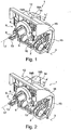
- Open-end spinning device 1 shown has a bearing device 2, with which it is limited pivotally mounted on a stationary, usually machine-length bearing axis 3.
- the in the Figures 1 and 2 For reasons of clarity, spinning rotor 7, not shown in more detail, is rotatably mounted with its rotor shaft 4 in a direct bearing device 5 and is driven by a circumferential, machine-length (not shown) tangential belt on which the rotor shaft 4 bears from below.
- the rotor housing 6, in which the spinning cup 11 of the spinning rotor 7 rotates at high speed during the spinning process, is closed by a cover element 8.
- the direct bearing device 5 and the rotor housing 6 form a rotor shaft bearing device 9, which is connected via a pivot axis 10 to a sliver opening device 12 of the open-end spinning device 1.
- the rotor shaft bearing device 9 is positioned in an inoperative position in which a brake member 13 abuts the rotor shaft 4, which is positioned at this time spaced from the machine-length, further circulating tangential belt.
- sliver opening device 12 In the sliver opening device 12, as usual, rotatably mounted an opening roller, which during the spinning operation, for example, by a machine-length Tangential belt is driven. Furthermore, a so-called sliver feed cylinder is rotatably mounted in the sliver opening device 12, the drive of which is effected in the exemplary embodiment via a single drive, for example a stepping motor.
- the axes of rotation of the opening roller and the sliver feed cylinder are arranged orthogonal to the axis of rotation 17 of the spinning rotor 7 during the spinning process.
- an upper cover 16 and a lower cover 15 are attached, which prevent too rapid contamination of the open-end spinning device 1.
- the upper cover 16 in this case has a connection socket 14, in which a holder 18, in the embodiment of FIGS. 1 and 3a , A holder 18 A is set interchangeable in each case.
- a relatively low installation height h for example, via a clip closure, a relatively short thread withdrawal tube 19 A set, which has a length I.
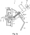
- FIG. 2 shows in perspective rear view of an open-end spinning device 1 for a workstation of an open-end rotor spinning machine, which operates in the so-called "Joint-Spinning-In” method and is equipped for this reason, for intermediate storage of the yarn with a thread as long as possible Fadenabzugsrschreibchen.
- the open-end spinning device 1 according to Fig. 2 corresponds to the holder 18 and the thread withdrawal tube 19 of the basis of the Fig.1 Open-end spinning device 1 described.
- Fig.2 can be seen in this embodiment on the terminal base 14 of the upper cover 16 interchangeably a holder 18 B set, the installation height H is well above the installation height h of the holder 18 A.
- the holder 18 B which has a relatively large installation height H, for example, via a clip closure, a relatively long thread withdrawal tube 19 B set, which has a length L.
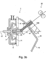
- the 3a shows in side view, partly in section like the Fig.1 , an open-end spinning device 1 for a workstation of an open-end rotor spinning machine, which is individually, preferably partially manually, spun.
- Such open-end spinning devices 1 are advantageously provided with a yarn clearer 21, and therefore require in the region between the mouth 22 of the yarn withdrawal tube 19A and a downstream yarn withdrawal device 20, some space, which through the use of a suitably adapted holder 18 A and an associated thread take-off tube 19 A is realized , For this reason, a holder 18 A is interchangeably fixed to the connection base 14 of the upper cover 16, which has a relatively small installation height h.
- a thread withdrawal tube 19 A set which also has a correspondingly short length I accordingly.
- the 3b also shows in side view and partly in section how the Fig.2 , an open-end spinning device 1 for a job of an open-end rotor spinning machine, which operates in the so-called "Joint-Spinning-In” method and is therefore equipped, for temporary storage of the Gamendes, with the longest possible Fadenabzugsrschreibchen.
- a holder 18 B is interchangeably fixed to the connection base 14 of the upper cover 16, which has a relatively large installation height H.
- a thread withdrawal tube 19 B is determined via a suitable fastening means, which has a relatively large length L.
- draw-off tubes 19 B with the long length L provide sufficient space for the twine to be temporarily stored in the event of a voltage drop and required for re-spinning in the "Joint-Spinning-In" method.
Landscapes
- Engineering & Computer Science (AREA)
- Mechanical Engineering (AREA)
- Textile Engineering (AREA)
- Spinning Or Twisting Of Yarns (AREA)
Description
Die Erfindung betrifft ein Verfahren zum Betreiben einer Offenend-Spinnvorrichtung für eine Offenend-Rotorspinn-maschine mit einem Spinnrotor, dessen Rotorschaft in einer Rotorschaftlagereinrichtung abgestützt und durch einen umlaufenden, maschinenlangen Tangentialriemen beaufschlagbar ist und dessen Rotortasse während des Spinnbetriebes mit hoher Drehzahl in einem unterdruckbeaufschlagbaren Rotorgehäuse umläuft. Das Rotorgehäuse ist durch ein Deckelelement verschließbar, in dem eine Fadenabzugsdüse sowie ein Fadenabzugsröhrchen angeordnet sind. Beabstandet zur Austrittsöffnung des Fadenabzugsröhrchens ist außerdem eine reversibel antreibbare Fadenabzugseinrichtung installiert.The invention relates to a method for operating an open-end spinning device for an open-end rotor spinning machine with a spinning rotor whose rotor shaft is supported in a rotor shaft bearing device and acted upon by a rotating machine-tangential tangential belt and its rotor cup during high-speed spinning operation in a rotor housing unterdruckbeaufschlagbaren circulates. The rotor housing can be closed by a cover element, in which a thread withdrawal nozzle and a thread withdrawal tube are arranged. In addition to the outlet opening of the thread withdrawal tube, a reversibly drivable thread withdrawal device is also installed.
In der Textilmaschinenindustrie sind im Zusammenhang mit Offenend-Rotorspinnmaschinen verschiedene Ausführungsformen Stand der Technik.
Die Offenend-Rotorspinnmaschinen können sich dabei sowohl bezüglich der Ausbildung ihrer Arbeitsstellen, speziell ihrer Offenend-Spinnvorrichtungen, als auch bezüglich der Arbeitsweise bzw. der Bedienung dieser Offenend-Spinnvorrichtungen nach einer Spinnunterbrechung unterscheiden.In the textile machinery industry, various embodiments are prior art in the context of open-end rotor spinning machines.
The open-end rotor spinning machines can differ in terms of the design of their jobs, especially their open-end spinning devices, as well as with respect to the operation or the operation of these open-end spinning devices after a spinning break.
Die
Insbesondere beim Wiederanspinnen der Arbeitsstellen nach einem Stromausfall, bei dem es an allen Arbeitsstellen der Spinnmaschine gleichzeitig zu einer Spinnunterbrechung gekommen ist, sind die Arbeitsweisen der bekannten Offenend-Rotorspinnmaschinen zum Teil recht unterschiedlich.In particular, when Wiederanspinnen the jobs after a power outage, in which it has come to a spinning break at all jobs of the spinning machine at the same time, the operations of the known open-end rotor spinning machines are sometimes quite different.
Durch die
Das heißt, die Arbeitsstellen dieser Offenend-Rotorspinnmaschinen sind so ausgebildet, dass sie nach einer Spinnunterbrechung ohne weitere Hilfe von außen selbsttätig wieder anspinnen können.That is, the jobs of these open-end rotor spinning machines are designed so that they can spontaneously spangle after a spin interruption without further help from the outside.
Nachteilig bei Offenend-Rotorspinnmaschinen, die mit solchen autarken Arbeitsstellen ausgerüstet sind, ist allerdings der relativ hohe Energiebedarf, insbesondere der Saugluftbedarf, den derartige Arbeitsstellen während eines Anspinnvorganges benötigen. Das hat zur Folge, dass nach einem Stromausfall immer nur eine begrenzte Anzahl, zum Beispiel zehn, dieser autarken Arbeitsstellen wieder gleichzeitig neu anspinnen können, mit der Folge, dass es aufgrund der Vielzahl von Arbeitsstellen solcher Offenend-Rotorspinnmaschinen stets eine geraume Zeit dauert, bis alle Arbeitsstellen der Spinnmaschine wieder neu angesponnen haben.
Entsprechend weisen diese bekannten Offenend-Rotorspinnmaschinen während der zahlreichen Wiederanspinnvorgänge stets nur einen verminderten Wirkungsgrad auf.A disadvantage of open-end rotor spinning machines, which are equipped with such self-sufficient jobs, however, is the relatively high energy consumption, in particular the Saugluftbedarf need such jobs during a piecing process. This has the consequence that after a power failure only a limited number, for example, ten, these self-sufficient jobs again simultaneously spindles can, with the result that it always takes a long time due to the large number of jobs such open-end rotor spinning machines until all workstations have spun the spinning machine again.
Accordingly, these known open-end rotor spinning always have only a reduced efficiency during the numerous Wiederanspinnvorgänge.
Des Weiteren sind beispielsweise durch die
Es ist leicht nachvollziehbar, dass bei derartigen Offenend-Rotorspinnmaschinen nach einem Stromausfall, durch den es an allen Arbeitsstellen der Offenend-Rotorspinnmaschine zu einer Spinnunterbrechung gekommen ist, selbst mehrere Anspinnwagen eine noch längere Zeit benötigen, um die zahlreichen Arbeitsstellen der Offenend-Rotorspinnmaschine wieder neu anzuspinnen.
Das bedeutet, die durch die
It is easy to understand that in such open-end rotor spinning after a power outage, which has come at all jobs of the open-end rotor spinning machine to a spinning break, even more Anspinnwagen need a longer time to the many jobs of the open-end rotor spinning machine again to spin.
That means that through the
Durch die
Des Weiteren weist jede Arbeitsstelle dieser semiautomatischen Offenend-Rotorspinnmaschinen eine Einrichtung zum definierten Ablängen eines vom Bedienpersonal manuell von der Kreuzspule zurückgeholten Fadens, eine Speichereinrichtung zur Aufnahme einer bestimmten Fadenmenge sowie eine gezielt ansteuerbare Antriebseinrichtung zum Abheben der Kreuzspule von der Spulenantriebswalze auf.
Bei diesen semiautomatischen Offenend-Rotorspinnmaschinen ist der Antrieb der Fadenabzugseinrichtung jeweils reversibel antreibbar. Außerdem verfügt jede Arbeitsstelle über eine manuell aktivierbare Steuereinrichtung, durch die der Anspinnvorgang gestartet werden kann, wobei während des Anspinnvorganges der Antrieb der Fadenabzugseinrichtung, der Antrieb des Faserbandeinzugszyünders sowie die Antriebseinrichtung zum Abheben der Kreuzspule entsprechend einem vorgegebenen Anspinnprogramm angesteuert werden.By the
Furthermore, each workstation of this semi-automatic open-end rotor spinning machine has a device for the defined cutting to length of a thread manually retrieved by the operating staff from the cross-wound bobbin, a storage device for receiving a certain amount of thread and a selectively controllable drive means for lifting the cheese from the bobbin drive roller.
In these semi-automatic open-end rotor spinning machines, the drive of the thread withdrawal device can each be reversibly driven. In addition, each workstation has a manually activatable control device by which the piecing process can be started, wherein during the piecing process, the drive of the thread take-off device, the drive of the sliver picking cycle and the drive device for lifting the cross-wound bobbin are controlled according to a predetermined piecing program.
Das heißt, die Arbeitsstellen solcher semiautomatischen Offenend-Rotorspinnmaschinen sind so ausgebildet, dass sie nach einer Spinnunterbrechung wieder problemlos angesponnen werden können, ohne dass dazu ein spezielles, kostenintensives Serviceaggregat notwendig ist. Die Qualität der erstellten Anspinner entspricht dabei den heutigen hohen Qualitätsstandards.That is, the jobs of such semi-automatic open-end rotor spinning machines are designed so that they can be spun easily after a spin interruption without the need for a special, costly service unit is necessary. The quality of the created piecing meets today's high quality standards.
Insgesamt stellen derartige semiautomatischen Offenend-Rotorspinnmaschinen verhältnismäßig kostengünstige Textilmaschinen dar. Allerdings ist auch bei diesen bekannten semiautomatischen Offenend-Rotorspinnmaschinen nachteilig, dass nach einem Stromausfall, bei dem es an allen Arbeitsstellen der Textilmaschine gleichzeitig zu einer Spinnunterbrechung kommt, die zahlreichen Arbeitsstellen wieder nacheinander zeitaufwendig einzeln neu angesponnen werden müssen, wobei das Bedienpersonal jeweils einen Teil der Arbeit jedes Anspinnvorganges übernehmen muss.Overall, such semiautomatic open-end rotor spinning machines are relatively inexpensive textile machines. However, even with these known semi-automatic open-end rotor spinning machines disadvantageous that after a power failure in which it comes at all jobs of the textile machine at the same time to a spinning break, the numerous jobs again time consuming individually need to be re-spun, the operator must take part of the work each piecing process.
Insbesondere in Gebieten, in denen häufiger mit Stromausfällen gerechnet werden muss, sind außerdem seit langem auch Offenend-Rotorspinnmaschinen im Einsatz, die im so genannten "Joint-Spinning-In"-Verfahren arbeiten.
Bei diesem auch als Massenanspinnen bekannten Verfahren spinnt eine Offenend-Rotorspinnmaschine nach einem Stromausfall die Offenend-Spinnvorrichtungen aller ihrer Arbeitsstellen gleichzeitig neu an.
Eine Offenend-Rotorspinnmaschine, die nach diesem seit langem bekannten Anspinnverfahren arbeitet, ist beispielsweise in der
In this method, which is also known as mass piecing, an open-end rotor spinning machine, after a power failure, simultaneously spins the open-end spinning devices of all its work stations at the same time.
An open-end rotor spinning machine, which works according to this long-known piecing process, is for example in the
Bei dieser bekannten Offenend-Rotorspinnmaschine erfolgt eine definierte Außerbetriebnahme aller ihrer Arbeitsstellen, wenn zum Beispiel die Versorgungsspannung ausfällt und nicht innerhalb von zwei Sekunden zurückkehrt.In this known open-end rotor spinning machine takes a defined decommissioning of all their jobs, for example, if the supply voltage fails and does not return within two seconds.
Das heißt, bei Offenend-Rotorspinnmaschinen, die nach dem "Joint-Spinning-In"-Verfahren arbeiten, wird beispielsweise an den Arbeitsstellen nach zwei Sekunden jeweils für ein gesteuertes Abbremsen der Auflaufspule gesorgt, gleichzeitig der jeweilige Abstand des Garnendes von der Fasersammelrinne des zugehörigen Spinnrotors ermittelt und für die spätere Wiederinbetriebnahme der Arbeitsstelle in einem Rechner gespeichert.
Das heißt, an allen Arbeitsstellen derartiger Offenend-Rotorspinnmaschinen verbleibt das Garnende bei einer Spinnunterbrechung stets im Bereich des jeweiligen Fadenabzugsröhrchens der Offenend-Spinnvorrichtung der Arbeitsstelle, das aus diesem Grunde eine relativ große Länge aufweist.That is, in open-end rotor spinning machines, which operate in accordance with the "Joint-Spinning-In" method, for example, at the workstations after two seconds each provided for a controlled braking of the package, at the same time the respective distance of the yarn end of the fiber collection channel of the associated Spinning rotor determined and stored for later recommissioning of the job in a computer.
That is, at all jobs such open-end rotor spinning machines the yarn end remains at a spinning interruption always in the range of the respective thread withdrawal tube of the open-end spinning device of the job, which for this reason has a relatively large length.
Bei diesen beispielsweise durch die
Nach einer vorgegebenen Zeitspanne werden die neu angesponnenen Fäden durch die jetzt wieder in Abzugsrichtung laufenden Fadenabzugseinrichtungen abgezogen.For example, by the
After a predetermined period of time, the newly spun threads are withdrawn through the now again in the withdrawal direction current thread withdrawal devices.
In der Praxis bedeutet dies, dass Offenend-Rotorspinnmaschinen, die im "Joint-Spinning-In"-Verfahren arbeiten, nach einem Stromausfall wieder deutlich schneller betriebsbereit sind, als Offenend-Rotorspinnmaschinen, deren Arbeitsstellen nach einem Stromausfall erst wieder nach und nach neu angesponnen werden müssen. Allerdings entsprechen die Anspinner, die im "Joint-Spinning-In"-Verfahren produziert werden, in der Regel keinen hohen Qualitätsstandards und würden durch einen Garnreiniger als Garnfehler sofort wieder herausgeschnitten.
Um dies zu vermeiden, wird bei Offenend-Rotorspinnmaschinen, die im "Joint-Spinning-In"-Verfahren arbeiten, in der Regel auf den Einsatz von Garnreinigern verzichtet, mit der Folge, dass das produzierte Garn hohen Qualitätsanforderungen oft nicht entspricht.In practice, this means that open-end rotor spinning machines, which work in the "Joint-Spinning-In" method, are operational again much faster after a power failure than open-end rotor spinning machines whose workstations after a power failure only gradually re-spun Need to become. However, the piecers produced in the "Joint-Spinning-In" process generally do not meet high quality standards and would be cut out immediately by a yarn cleaner as yarn defects.
In order to avoid this, in open-end rotor spinning machines, which work in the "Joint-Spinning-In" -Procedure, usually dispenses with the use of yarn cleaners, with As a result, the yarn produced often does not meet high quality requirements.
Ausgehend von Offenend-Rotorspinnmaschinen der vorstehend beschriebenen Gattung liegt der Erfindung die Aufgabe zugrunde, Verfahren zum Betreiben einer Offenend-Spinnvorrichtung zu entwickeln, das es ermöglicht, eine Offenend-Rotorspinnmaschine wahlweise entweder im "Joint-Spinning-ln"-Verfahren zu betreiben oder die Offenend-Spinnvorrichtungen der Arbeitsstellen der Offenend-Rotorspinnmaschinen einzeln, beispielsweise semiautomatisch, anzuspinnen, das heißt, eine Offenend-Spinnvorrichtung zu schaffen, die so modifiziert werden kann, dass sie entweder nach einem Stromausfall schnell wieder betriebsbereit ist, oder durch die Anordnung eines zwischen dem Fadenabzugsröhrchen und der Fadenabzugseinrichtung eingeschalteten Garnreinigers so gestaltet ist, dass die Qualität des Fadens sowie der Anspinner überwacht werden und damit die Produktion hochwertigen Garnes gewährleistet wird.Starting from open-end rotor spinning machines of the type described above, the invention has the object to develop methods for operating an open-end spinning device, which makes it possible to operate an open-end rotor spinning machine either either in the "Joint-Spinning-ln" method or Open-end spinning devices of the open-end rotor spinning machine workplaces are to be individually wound, for example semi-automatically, that is to provide an open-end spinning device that can be modified to recover quickly either after a power failure or through the arrangement of one between the two Thread take-off tube and the thread take-off device turned on yarn cleaner is designed so that the quality of the thread and the piecing are monitored and thus the production of high-quality yarn is guaranteed.
Ausgehend von einer Offenend-Spinnvorrichtung der vorstehend beschriebenen Gattung wird diese Aufgabe erfindungsgemäß durch ein Verfahren zum Betreiben einer Offenend-Spinnvorrichtung gemäß dem Anspruch 1 gelöst.Starting from an open-end spinning device of the type described above, this object is achieved according to the invention by a method for operating an open-end spinning device according to
Die Länge des eingesetzten Fadenabzugsröhrchens ist dabei jeweils abhängig vom Anspinnverfahren, welches beim Wiederanspinnen der Offenend-Spinnvorrichtungen der betreffenden Offenend-Rotorspinnmaschine zum Einsatz kommt.The length of the thread withdrawal tube used in each case depends on the piecing process which is used in the piecing back of the open-end spinning devices of the relevant open-end rotor spinning machine.
Eine solche Ausbildung hat den Vorteil, dass, wenn die Offenend-Rotorspinnmaschine im "Joint-Spinning-In"-Verfahren betrieben werden soll, Fadenabzugsröhrchen eingesetzt werden können, die so lang sind, dass bei einem durch einen Spannungsabfall initiierten, gesteuerten Herunterfahren der Arbeitsstellen ein Verbleib der Gamenden innerhalb der Fadenabzugsröhrchen auch bei großen, das heißt, verzögert stillsetzbaren Auflaufspulen gewährleistet ist.Such a design has the advantage that when the open-end rotor spinning machine is to be operated in the "Joint-Spinning-In" method, thread withdrawal tubes can be used which are so long that, in the event of a voltage drop initiated, controlled shutdown of the jobs a whereabouts of the Gamenden within the thread withdrawal tube is guaranteed even with large, that is, delay can be set up packages.
Alternativ sind die Fadenabzugsröhrchen, wenn der Anspinnvorgang an den Arbeitsstellen jeweils einzeln und zum Beispiel zum Teil manuell ausgeführt werden soll, kürzer ausgebildet, so dass ein Rückholen des auf die Auflaufspule aufgelaufenen Garnendes und dessen anschließendes Einführen in das Fadenabzugsröhrchen auch bei Anwesenheit eines Garnreinigers problemlos möglich ist.Alternatively, if the piecing operation at the work stations is to be performed individually and, for example, partially manually, the thread withdrawal tubes are made shorter, so that retrieval of the yarn end accumulated on the package and its subsequent insertion into the thread withdrawal tube is possible without difficulty even in the presence of a yarn cleaner is.
Die unterschiedlich langen Fadenabzugsröhrchen sind außerdem durch die vorteilhafterweise bezüglich ihrer Höhe verschieden großen Halter optimal im Deckelelement der Offenend-Rotorspinnvorrichtung festlegbar. Das heißt, abhängig von der Länge des Fadenabzugsröhrchens kommt jeweils ein in seiner Einbauhöhe optimal angepasster Halter zum Einsatz.The differently long thread withdrawal tubes are also optimally fixable in the cover element of the open-end rotor spinning device advantageously by the holder advantageously different in height. That is, depending on the length of the thread withdrawal tube, each one in its installation height optimally adapted holder is used.
In vorteilhafter Ausführungsform ist vorgesehen, dass bei einem vorgesehen Einsatz des so genannten "Joint-Spinning-In"-Verfahrens Fadenabzugsröhrchen zum Einsatz kommen, deren Länge jeweils größer ist, als die Länge von Fadenabzugsröhrchen, die Verwendung finden, wenn die Offenend-Spinnvorrichtungen der Offenend-Rotorspinnmaschine im Einzelanspinnen-Verfahren und damit vorzugsweise mit Garnreinigem betrieben werden.In an advantageous embodiment, it is provided that in an intended use of the so-called "Joint-Spinning-In" thread withdrawal tubes are used, the length of each is greater than the length of thread withdrawal tubes, which find use when the open-end spinning devices of Open-end rotor spinning machine in Einzelanspinnen method and thus preferably operated with Garnreinigem.
Wie vorstehend bereits angedeutet, kann beim "Joint-Spinning-In"-Verfahren durch den Einsatz relativ langer Fadenabzugsröhrchen sichergestellt werden, dass auch bei großen Auflaufspulen, die bekanntlich eine deutlich höhere kinetische Energie als kleine Auflaufspulen aufweisen, das Garnende stets, was zwingend erforderlich ist, innerhalb des Fadenabzugsröhrchens verbleibt.
Beim Einzelanspinnen der Arbeitsstellen kann anderseits durch den Einsatz von kurzen Fadenabzugsröhrchen auf einfache Weise in dem Bereich zwischen Fadenabzugsröhrchen und Fadenabzugseinrichtung der Platz geschaffen werden, der zum Einbau eines Garnreinigers benötigt wird, wobei gleichzeitig ausreichend Raum bleibt, um das zurückgeholte Garnende in das Fadenabzugsröhrchen einführen zu können.As already indicated above, in the "Joint-Spinning-In" method can be ensured by the use of relatively long thread withdrawal tube that even with large packages, which are known to have a significantly higher kinetic energy than small packages, the yarn always, which is absolutely necessary is, remains within the thread withdrawal tube.
On the other hand, when piecing workstations, the use of short draw-off tubes can easily create the space needed to install a yarn cleaner in the area between the draw-off tube and the draw-off device while leaving sufficient space to insert the recovered yarn end into the draw-off tube can.
In vorteilhafter Ausführungsform kommen beim Einsatz langer Fadenabzugsröhrchen vorzugsweise Halter mit einer relativ großen Einbauhöhe zum Einsatz, während bei kurzen Fadenabzugsröhrchen vorzugsweise Halter Verwendung finden, die eine relativ geringe Einbauhöhe aufweisen.
Auf diese Weise ist stets eine optimale Ausnutzung der bei Arbeitsstellen oberhalb der Offenend-Rotorspinnvorrichtungen gegebenen, bekanntlich etwas beengten Raumverhältnisse gewährleistet.In an advantageous embodiment, when using long thread withdrawal tubes preferably holders with a relatively large installation height are used, while at short thread withdrawal tube preferably find use holder, which have a relatively low installation height.
In this way, an optimal utilization of given at work above the open-end rotor spinning devices, known to be somewhat cramped space conditions is always guaranteed.
In vorteilhafter Ausführungsform sind die Fadenabzugsröhrchen jeweils aus Glas gefertigt, während die Halter jeweils aus Kunststoff hergestellt sind. Fadenabzugsröhrchen aus Glas stellen im Textilmaschinenbau seit langem bewährte Bauteile dar, die außerdem leicht und kostengünstig in nahezu jeder Länge zu fertigen sind.
Die Fertigung der Halter aus einem Kunststoff hat ebenfalls den Vorteil, dass ein solcher Halter relativ einfach und kostengünstig bei guter Festigkeit zu fertigen ist. Außerdem bildet ein Halter aus Kunststoff eine gegen ungünstige Umwelteinflüsse weitestgehend resistente Konstruktion.In an advantageous embodiment, the thread withdrawal tubes are each made of glass, while the holders are each made of plastic. Thread extractor tubes made of glass have long been proven components in textile machinery, which are also easy and inexpensive to manufacture in almost any length.
The production of the holder made of a plastic also has the advantage that such a holder is relatively easy and inexpensive to manufacture with good strength. In addition, a plastic holder forms a largely resistant to unfavorable environmental influences construction.
In vorteilhafter Ausführungsform ist des Weiteren vorgesehen, dass die Fadenabzugsröhrchen im Betriebszustand der Offenend-Spinnvorrichtungen in die Halter eingeclipst sind.In an advantageous embodiment, it is further provided that the thread withdrawal tubes are clipped into the holder in the operating state of the open-end spinning devices.
Eine solche Befestigungsmethode hat den Vorteil, dass die beiden Bauteile bei stillgesetzten Arbeitsstellen jederzeit problemlos auseinandergenommen oder zusammengefügt werden können. Das in ihrem zugehörigen Halter jeweils durch eine Clipsverbindung sicher befestigte Fadenabzugsröhrchen gewährleistet außerdem während des Spinnprozesses jederzeit einen ordnungsgemäßen Betrieb der Offenend-Rotorspinnvorrichtung der Arbeitsstelle.Such a method of attachment has the advantage that the two components can be easily taken apart or put together at shut down jobs anytime. The thread withdrawal tube securely fastened in its associated holder by a clip connection also ensures proper operation of the open-end rotor spinning device of the work site at any time during the spinning process.
Weitere Einzelheiten der Erfindung sind einem nachfolgend anhand der Zeichnungen dargestellten Ausführungsbeispiel entnehmbar.Further details of the invention are shown in an embodiment shown below with reference to the drawings.
Es zeigt:
- Fig. 1
- in perspektivischer Rückansicht eine Offenend-Spinnvorrichtung für eine Offenend-Rotorspinnmaschine, bei der die Arbeitsstellen mit einem Garnreiniger ausgestattet sind und bei der die Offenend-Spinnvorrichtungen einzeln, das heißt, nacheinander angesponnen werden,
- Fig. 2
- in perspektivischer Rückansicht eine Offenend-Spinnvorrichtung für eine Offenend-Rotorspinnmaschine, die im "Joint-Spinning-In"-Verfahren arbeitet,
- Fig. 3a
- in Seitenansicht, teilweise im Schnitt, eine Offenend-Spinnvorrichtung mit einem Halter und einem Fadenabzugsröhrchen, wie sie beim Einzelanspinnen zum Einsatz kommen,
- Fig. 3b
- in Seitenansicht, teilweise im Schnitt, eine Offenend-Spinnvorrichtung mit einem Halter und einem Fadenabzugsröhrchen, wie sie im "Joint-Spinning-In"-Verfahren zum Einsatz kommen.
- Fig. 1
- in perspective rear view of an open-end spinning device for an open-end rotor spinning machine, in which the jobs with a yarn cleaner and in which the open-end spinning devices are individually wound, that is, one after the other,
- Fig. 2
- in a perspective rear view of an open-end spinning device for an open-end rotor spinning machine, which operates in the "Joint Spinning-In" method,
- Fig. 3a
- in side view, partly in section, an open-end spinning device with a holder and a thread withdrawal tube, as used in Einzelanspinnen used
- Fig. 3b
- in side view, partially in section, an open-end spinning device with a holder and a thread withdrawal tube, as used in the "Joint-Spinning-In" method used.
Die in
Der in den
Bei (nicht dargestellter) geöffneter Offenend-Spinnvorrichtung 1 ist die Rotorschaftlagereinrichtung 9 in einer Außerbetriebsstellung positioniert, in der ein Bremselement 13 am Rotorschaft 4 anliegt, der zu diesem Zeitpunkt beabstandet zum maschinenlangen, weiter umlaufenden Tangentialriemen positioniert ist.In the
The in the
In (not shown) open open-
In der Faserbandauflöseeinrichtung 12 ist, wie üblich, rotierbar eine Auflösewalze gelagert, die während des Spinnbetriebes beispielsweise durch einen maschinenlangen Tangentialriemen angetrieben wird. Des Weiteren ist in der Faserbandauflöseeinrichtung 12 ein so genannter Faserbandeinzugszylinder rotierbar gelagert, dessen Antrieb im Ausführungsbeispiel über einen Einzelantrieb, zum Beispiel einen Schrittmotor, erfolgt. Die Rotationsachsen der Auflösewalze und des Faserbandeinzugzylinders sind während des Spinnprozesses orthogonal zur Rotationsachse 17 des Spinnrotors 7 angeordnet.In the
An der Faserbandauflöseeinrichtung 12 der Offenend-Spinnvorrichtung 1 sind eine obere Abdeckung 16 und eine untere Abdeckung 15 befestigt, die eine zu schnelle Verschmutzung der Offenend-Spinnvorrichtung 1 verhindern. Die obere Abdeckung 16 weist dabei einen Anschlusssockel 14 auf, in dem ein Halter 18, im Ausführungsbeispiel der
Wie nachfolgend anhand der
As follows from the
Die
Die Offenend-Spinnvorrichtung 1 gemäß
Wie aus
Wie nachfolgend anhand der
As follows from the
Die
Derartige Offenend-Spinnvorrichtungen 1 sind vorteilhafterweise mit einem Garnreiniger 21 ausgestattet und benötigen daher im Bereich zwischen der Mündung 22 des Fadenabzugsröhrchens 19A und einer nachgeschalteten Fadenabzugseinrichtung 20 etwas Platz, was durch den Einsatz eines entsprechend angepassten Halters 18A sowie eines zugehörigen Fadenabzugsröhrchens 19A realisiert wird.
Aus diesem Grunde ist am Anschlusssockel 14 der oberen Abdeckung 16 auswechselbar ein Halter 18A festgelegt, der eine verhältnismäßig geringe Einbauhöhe h aufweist. Im Halter 18A ist, beispielsweise über einen Clipverschluss, ein Fadenabzugsröhrchen 19A festgelegt, das entsprechend ebenfalls eine relativ kurze Länge I aufweist.The
Such open-
For this reason, a holder 18 A is interchangeably fixed to the
Die
Wie ersichtlich, ist am Anschlusssockel 14 der oberen Abdeckung 16 auswechselbar ein Halter 18B festgelegt, der eine verhältnismäßig große Einbauhöhe H aufweist.
Im Halter 18B ist über ein geeignetes Befestigungsmittel ein Fadenabzugsröhrchen 19B festgelegt, das eine relativ große Länge L aufweist.
In der Praxis bieten Fadenabzugsröhrchen 19B mit der großen Länge L ausreichend Platz für das bei einem Spannungsabfall zwischenzuspeichernde und beim Wiederanspinnen im "Joint-Spinning-In"-Verfahren zwingend benötigte Garnende.As can be seen, a holder 18 B is interchangeably fixed to the
In the holder 18 B , a thread withdrawal tube 19 B is determined via a suitable fastening means, which has a relatively large length L.
In practice, draw-off tubes 19 B with the long length L provide sufficient space for the twine to be temporarily stored in the event of a voltage drop and required for re-spinning in the "Joint-Spinning-In" method.
Claims (4)
- Method for operating an open-end spinning device (1) for an open-end rotor spinning machine comprising a spinning rotor (7), the rotor shaft (4) of which is supported in a rotor shaft bearing device (9) and can be pressurised by a rotating, machine-length tangential belt, and the rotor cup (11) of which rotates during the spinning operation at high speed in a rotor housing (6) which can be charged with negative pressure, which can be closed by a cover element (8), on which a thread take-off nozzle (23) and a thread take-off tube (19A, 19B) are arranged, wherein a reversibly drivable thread take-off device (20) is installed spaced apart from the opening (22) of the thread take-off tube (19),
characterised in that,
a cover (16) of the open-end spinning device (1) arranged at the top is provided respectively with a replaceable holder (18A, 18B) projecting over the latter for one end of a thread take-off tube (19A, 19B), which is connected at its other end to the cover element (8) in the region of the thread take-off nozzle (23), wherein two holders (18A, 18B), which have different dimensions with respect to their height projecting over the cover (16) arranged at the top, and the thread take-off tubes (19A, 19B), which vary in length (I, L) according to the difference in height, can be secured alternatively in the cover (16), and wherein a thread take-off tube (19A, 19B) is used, the length (I, L) of which is dependent respectively on the piecing method which is used when re-piecing the open-end spinning devices of the relevant open-end rotor spinning machine. - Method according to claim 1, characterised in that with the intended use of the so-called "joint spinning-in" method, thread take-off tubes (19B) are used, the length (L) of which is greater than the length (I) of thread take-off tubes (19A), which are used when the open-end spinning devices (1) of the open-end rotor spinning machine are operated in the individual piecing method.
- Method according to claim 2, characterised in that when using thread take-off tubes (19B) for the so-called "joint spinning-in" method holders (18B) are used, which have a relatively large installation height (H), whereas with thread take-off tubes (19A), which are used when the open-end rotor spinning devices (1) of the open-end rotor spinning machine are operated in an individual piecing method, holders (18A) are used which have a low installation height (h).
- Method according to claim 1, characterised in that the thread take-off tubes (19A, 19B) of the open-end- spinning devices (1) are clipped respectively into a holder (18A, 18B).
Applications Claiming Priority (1)
| Application Number | Priority Date | Filing Date | Title |
|---|---|---|---|
| DE102014008748.4A DE102014008748A1 (en) | 2014-06-12 | 2014-06-12 | Open-end spinning device |
Related Parent Applications (1)
| Application Number | Title | Priority Date | Filing Date |
|---|---|---|---|
| DE102014008748 Previously-Filed-Application | 2014-06-12 |
Publications (2)
| Publication Number | Publication Date |
|---|---|
| EP2957663A1 EP2957663A1 (en) | 2015-12-23 |
| EP2957663B1 true EP2957663B1 (en) | 2017-03-08 |
Family
ID=53298075
Family Applications (1)
| Application Number | Title | Priority Date | Filing Date |
|---|---|---|---|
| EP15001402.5A Not-in-force EP2957663B1 (en) | 2014-06-12 | 2015-05-08 | Method for operating an open-end spinning machine |
Country Status (3)
| Country | Link |
|---|---|
| EP (1) | EP2957663B1 (en) |
| CN (1) | CN105316812B (en) |
| DE (1) | DE102014008748A1 (en) |
Families Citing this family (5)
| Publication number | Priority date | Publication date | Assignee | Title |
|---|---|---|---|---|
| JP6971915B2 (en) * | 2018-06-05 | 2021-11-24 | 株式会社荏原製作所 | Plating method, plating equipment, and method for estimating critical current density |
| DE102019116278A1 (en) * | 2019-06-14 | 2020-12-17 | Saurer Intelligent Technology AG | Textile machine |
| DE102020101840A1 (en) * | 2020-01-27 | 2021-07-29 | Maschinenfabrik Rieter Ag | Thread guide unit, open-end rotor spinning machine and method for operating a spinning station |
| EP3919659B1 (en) * | 2020-06-03 | 2023-02-15 | Saurer Spinning Solutions GmbH & Co. KG | Open end rotor spinning device and method for operating an open end rotor spinning device |
| DE102020124125A1 (en) | 2020-09-16 | 2022-03-17 | Saurer Spinning Solutions Gmbh & Co. Kg | Textile machine producing cheeses |
Family Cites Families (15)
| Publication number | Priority date | Publication date | Assignee | Title |
|---|---|---|---|---|
| GB1192377A (en) * | 1966-11-09 | 1970-05-20 | Tmm Research Ltd | Improvements relating to the Spinning of Textile Yarns |
| CH672800A5 (en) * | 1986-03-19 | 1989-12-29 | Schlafhorst & Co W | |
| DE3635510C2 (en) | 1986-10-18 | 1995-10-26 | Schlafhorst & Co W | Method and device for decommissioning and subsequent recommissioning of an OE rotor spinning machine |
| DE3723504A1 (en) * | 1987-07-16 | 1989-01-26 | Schlafhorst & Co W | TWISTING ELEMENT FOR AN OPEN-END ROTOR SPINNING DEVICE |
| US5323599A (en) * | 1988-04-08 | 1994-06-28 | W. Schlafhorst & Co. | Process and apparatus for producing hairiness in an open-end spinning yarn |
| JPH03193927A (en) * | 1989-12-20 | 1991-08-23 | Asahi Chem Ind Co Ltd | False-twisting device in spinning equipment |
| DE19544617B4 (en) * | 1995-11-30 | 2008-06-12 | Maschinenfabrik Rieter Ag | Adapter for open-end spinning devices |
| US5913806A (en) * | 1997-11-08 | 1999-06-22 | Rieter Ingolstadt Spinnereimaschinenbau Ag | Device to convey fibers to the collection surface of a spinning rotor |
| DE19749492A1 (en) * | 1996-11-16 | 1998-05-20 | Rieter Ingolstadt Spinnerei | Combined feed tube and rotor box cover for open end spinning unit |
| DE19709747B4 (en) * | 1997-03-10 | 2005-10-06 | Saurer Gmbh & Co. Kg | Apparatus for preparing a piecing operation on an open-end spinning device |
| DE19836073A1 (en) * | 1998-08-10 | 2000-02-17 | Schlafhorst & Co W | Fiber channel plate for an open-end spinning device |
| DE19915924B4 (en) * | 1999-04-09 | 2009-12-10 | Rieter Ingolstadt Gmbh | Thread guide tube |
| DE19917968B4 (en) | 1999-04-21 | 2007-08-23 | Saurer Gmbh & Co. Kg | Service unit for a textile machine producing cross-wound bobbins |
| DE10139075A1 (en) | 2001-08-09 | 2003-02-20 | Schlafhorst & Co W | Open-end rotor spinning machine |
| DE102005036485A1 (en) | 2005-08-03 | 2007-02-08 | Saurer Gmbh & Co. Kg | Open-end rotor spinning machine |
-
2014
- 2014-06-12 DE DE102014008748.4A patent/DE102014008748A1/en not_active Withdrawn
-
2015
- 2015-05-08 EP EP15001402.5A patent/EP2957663B1/en not_active Not-in-force
- 2015-06-09 CN CN201510312581.7A patent/CN105316812B/en active Active
Also Published As
| Publication number | Publication date |
|---|---|
| CN105316812B (en) | 2017-09-22 |
| DE102014008748A1 (en) | 2015-12-17 |
| EP2957663A1 (en) | 2015-12-23 |
| CN105316812A (en) | 2016-02-10 |
Similar Documents
| Publication | Publication Date | Title |
|---|---|---|
| EP2957663B1 (en) | Method for operating an open-end spinning machine | |
| EP2801646B1 (en) | Method for operating an open end rotor spinning machine | |
| DE10139072B4 (en) | Service unit for re-spinning jobs of an open-end spinning machine | |
| EP1749906A2 (en) | Piecing arrangement for a rotor type open-end spinning machine | |
| DE102006047288A1 (en) | Workplace of a textile machine | |
| EP3260584B1 (en) | Method for optimizing the production of a rotor spinning machine | |
| EP2955143B1 (en) | Semi-automatic textile machine which produces crosswound bobbins | |
| EP2657380A2 (en) | Method and apparatus for operating workstations of an open-end rotor spinning machine | |
| EP3533739B1 (en) | Method for operating a textile machine and textile machine | |
| EP2966201A2 (en) | Semi-automatic opening rotor spinning machine | |
| EP2192213B1 (en) | Service device for supplying the workplaces of an open-end spinning machine | |
| EP3144418A1 (en) | Method for adapting a work-side design of an open ended rotor spinning machine related to yarn section production | |
| EP3312317B1 (en) | Workstation of a textile machine with a pneumatic thread storage body and textile machine | |
| WO2008128596A1 (en) | Open-end spinning machine | |
| DE102006050220B4 (en) | Method and device for operating a cheese-producing textile machine | |
| DE102013014195A1 (en) | Elimination of a thread break when winding a thread on a cross-wound bobbin | |
| DE19917968A1 (en) | Travelling service unit, especially for an open-end spinning machine, has different piecing program for end breaks and for bobbin start-up | |
| EP2251292B1 (en) | Paraffin device for a textile machine for the production of cross-wound bobbins | |
| EP2682509B1 (en) | Stretching unit for a spinning machine | |
| DE102015118987A1 (en) | Method for operating a spinning machine with a fully automatic piecing device and spinning machine with a fully automatic piecing device | |
| EP2660376A1 (en) | Apparatus for creating a spinnable yarn end in an open-end spinning machine | |
| DE102016108391A1 (en) | A process for Garnmassenanspinnen on the jobs of a rotor spinning machine and means for its execution | |
| DE102007038871A1 (en) | Joining-on thread to spindle of open-ended spinning machines from mobile service unit controls acceleration as spun-on thread is pulled from spinning unit | |
| EP3909896A1 (en) | Spinning device and method for piecing | |
| EP3031760A1 (en) | Method and device for operating a workstation of a textile machine for creating cross-wound spools |
Legal Events
| Date | Code | Title | Description |
|---|---|---|---|
| PUAI | Public reference made under article 153(3) epc to a published international application that has entered the european phase |
Free format text: ORIGINAL CODE: 0009012 |
|
| AK | Designated contracting states |
Kind code of ref document: A1 Designated state(s): AL AT BE BG CH CY CZ DE DK EE ES FI FR GB GR HR HU IE IS IT LI LT LU LV MC MK MT NL NO PL PT RO RS SE SI SK SM TR |
|
| AX | Request for extension of the european patent |
Extension state: BA ME |
|
| 17P | Request for examination filed |
Effective date: 20160623 |
|
| RBV | Designated contracting states (corrected) |
Designated state(s): AL AT BE BG CH CY CZ DE DK EE ES FI FR GB GR HR HU IE IS IT LI LT LU LV MC MK MT NL NO PL PT RO RS SE SI SK SM TR |
|
| GRAP | Despatch of communication of intention to grant a patent |
Free format text: ORIGINAL CODE: EPIDOSNIGR1 |
|
| RIC1 | Information provided on ipc code assigned before grant |
Ipc: D01H 4/40 20060101AFI20161027BHEP |
|
| INTG | Intention to grant announced |
Effective date: 20161111 |
|
| GRAS | Grant fee paid |
Free format text: ORIGINAL CODE: EPIDOSNIGR3 |
|
| GRAA | (expected) grant |
Free format text: ORIGINAL CODE: 0009210 |
|
| AK | Designated contracting states |
Kind code of ref document: B1 Designated state(s): AL AT BE BG CH CY CZ DE DK EE ES FI FR GB GR HR HU IE IS IT LI LT LU LV MC MK MT NL NO PL PT RO RS SE SI SK SM TR |
|
| REG | Reference to a national code |
Ref country code: GB Ref legal event code: FG4D Free format text: NOT ENGLISH |
|
| REG | Reference to a national code |
Ref country code: CH Ref legal event code: EP Ref country code: AT Ref legal event code: REF Ref document number: 873613 Country of ref document: AT Kind code of ref document: T Effective date: 20170315 |
|
| REG | Reference to a national code |
Ref country code: IE Ref legal event code: FG4D Free format text: LANGUAGE OF EP DOCUMENT: GERMAN |
|
| REG | Reference to a national code |
Ref country code: DE Ref legal event code: R096 Ref document number: 502015000663 Country of ref document: DE |
|
| REG | Reference to a national code |
Ref country code: LT Ref legal event code: MG4D |
|
| REG | Reference to a national code |
Ref country code: NL Ref legal event code: MP Effective date: 20170308 |
|
| PG25 | Lapsed in a contracting state [announced via postgrant information from national office to epo] |
Ref country code: FI Free format text: LAPSE BECAUSE OF FAILURE TO SUBMIT A TRANSLATION OF THE DESCRIPTION OR TO PAY THE FEE WITHIN THE PRESCRIBED TIME-LIMIT Effective date: 20170308 Ref country code: NO Free format text: LAPSE BECAUSE OF FAILURE TO SUBMIT A TRANSLATION OF THE DESCRIPTION OR TO PAY THE FEE WITHIN THE PRESCRIBED TIME-LIMIT Effective date: 20170608 Ref country code: LT Free format text: LAPSE BECAUSE OF FAILURE TO SUBMIT A TRANSLATION OF THE DESCRIPTION OR TO PAY THE FEE WITHIN THE PRESCRIBED TIME-LIMIT Effective date: 20170308 Ref country code: HR Free format text: LAPSE BECAUSE OF FAILURE TO SUBMIT A TRANSLATION OF THE DESCRIPTION OR TO PAY THE FEE WITHIN THE PRESCRIBED TIME-LIMIT Effective date: 20170308 Ref country code: GR Free format text: LAPSE BECAUSE OF FAILURE TO SUBMIT A TRANSLATION OF THE DESCRIPTION OR TO PAY THE FEE WITHIN THE PRESCRIBED TIME-LIMIT Effective date: 20170609 |
|
| PG25 | Lapsed in a contracting state [announced via postgrant information from national office to epo] |
Ref country code: RS Free format text: LAPSE BECAUSE OF FAILURE TO SUBMIT A TRANSLATION OF THE DESCRIPTION OR TO PAY THE FEE WITHIN THE PRESCRIBED TIME-LIMIT Effective date: 20170308 Ref country code: SE Free format text: LAPSE BECAUSE OF FAILURE TO SUBMIT A TRANSLATION OF THE DESCRIPTION OR TO PAY THE FEE WITHIN THE PRESCRIBED TIME-LIMIT Effective date: 20170308 Ref country code: BG Free format text: LAPSE BECAUSE OF FAILURE TO SUBMIT A TRANSLATION OF THE DESCRIPTION OR TO PAY THE FEE WITHIN THE PRESCRIBED TIME-LIMIT Effective date: 20170608 Ref country code: ES Free format text: LAPSE BECAUSE OF FAILURE TO SUBMIT A TRANSLATION OF THE DESCRIPTION OR TO PAY THE FEE WITHIN THE PRESCRIBED TIME-LIMIT Effective date: 20170308 Ref country code: LV Free format text: LAPSE BECAUSE OF FAILURE TO SUBMIT A TRANSLATION OF THE DESCRIPTION OR TO PAY THE FEE WITHIN THE PRESCRIBED TIME-LIMIT Effective date: 20170308 Ref country code: LU Free format text: LAPSE BECAUSE OF NON-PAYMENT OF DUE FEES Effective date: 20170531 |
|
| PG25 | Lapsed in a contracting state [announced via postgrant information from national office to epo] |
Ref country code: NL Free format text: LAPSE BECAUSE OF FAILURE TO SUBMIT A TRANSLATION OF THE DESCRIPTION OR TO PAY THE FEE WITHIN THE PRESCRIBED TIME-LIMIT Effective date: 20170308 |
|
| PG25 | Lapsed in a contracting state [announced via postgrant information from national office to epo] |
Ref country code: RO Free format text: LAPSE BECAUSE OF FAILURE TO SUBMIT A TRANSLATION OF THE DESCRIPTION OR TO PAY THE FEE WITHIN THE PRESCRIBED TIME-LIMIT Effective date: 20170308 Ref country code: EE Free format text: LAPSE BECAUSE OF FAILURE TO SUBMIT A TRANSLATION OF THE DESCRIPTION OR TO PAY THE FEE WITHIN THE PRESCRIBED TIME-LIMIT Effective date: 20170308 Ref country code: SK Free format text: LAPSE BECAUSE OF FAILURE TO SUBMIT A TRANSLATION OF THE DESCRIPTION OR TO PAY THE FEE WITHIN THE PRESCRIBED TIME-LIMIT Effective date: 20170308 |
|
| PG25 | Lapsed in a contracting state [announced via postgrant information from national office to epo] |
Ref country code: PT Free format text: LAPSE BECAUSE OF FAILURE TO SUBMIT A TRANSLATION OF THE DESCRIPTION OR TO PAY THE FEE WITHIN THE PRESCRIBED TIME-LIMIT Effective date: 20170710 Ref country code: PL Free format text: LAPSE BECAUSE OF FAILURE TO SUBMIT A TRANSLATION OF THE DESCRIPTION OR TO PAY THE FEE WITHIN THE PRESCRIBED TIME-LIMIT Effective date: 20170308 Ref country code: SM Free format text: LAPSE BECAUSE OF FAILURE TO SUBMIT A TRANSLATION OF THE DESCRIPTION OR TO PAY THE FEE WITHIN THE PRESCRIBED TIME-LIMIT Effective date: 20170308 Ref country code: IS Free format text: LAPSE BECAUSE OF FAILURE TO SUBMIT A TRANSLATION OF THE DESCRIPTION OR TO PAY THE FEE WITHIN THE PRESCRIBED TIME-LIMIT Effective date: 20170708 |
|
| REG | Reference to a national code |
Ref country code: DE Ref legal event code: R097 Ref document number: 502015000663 Country of ref document: DE |
|
| PLBE | No opposition filed within time limit |
Free format text: ORIGINAL CODE: 0009261 |
|
| STAA | Information on the status of an ep patent application or granted ep patent |
Free format text: STATUS: NO OPPOSITION FILED WITHIN TIME LIMIT |
|
| PG25 | Lapsed in a contracting state [announced via postgrant information from national office to epo] |
Ref country code: DK Free format text: LAPSE BECAUSE OF FAILURE TO SUBMIT A TRANSLATION OF THE DESCRIPTION OR TO PAY THE FEE WITHIN THE PRESCRIBED TIME-LIMIT Effective date: 20170308 Ref country code: MC Free format text: LAPSE BECAUSE OF FAILURE TO SUBMIT A TRANSLATION OF THE DESCRIPTION OR TO PAY THE FEE WITHIN THE PRESCRIBED TIME-LIMIT Effective date: 20170308 |
|
| 26N | No opposition filed |
Effective date: 20171211 |
|
| REG | Reference to a national code |
Ref country code: IE Ref legal event code: MM4A |
|
| PG25 | Lapsed in a contracting state [announced via postgrant information from national office to epo] |
Ref country code: SI Free format text: LAPSE BECAUSE OF FAILURE TO SUBMIT A TRANSLATION OF THE DESCRIPTION OR TO PAY THE FEE WITHIN THE PRESCRIBED TIME-LIMIT Effective date: 20170308 |
|
| REG | Reference to a national code |
Ref country code: FR Ref legal event code: ST Effective date: 20180131 |
|
| PG25 | Lapsed in a contracting state [announced via postgrant information from national office to epo] |
Ref country code: LU Free format text: LAPSE BECAUSE OF NON-PAYMENT OF DUE FEES Effective date: 20170508 |
|
| REG | Reference to a national code |
Ref country code: BE Ref legal event code: MM Effective date: 20170531 |
|
| PG25 | Lapsed in a contracting state [announced via postgrant information from national office to epo] |
Ref country code: IE Free format text: LAPSE BECAUSE OF NON-PAYMENT OF DUE FEES Effective date: 20170508 |
|
| PG25 | Lapsed in a contracting state [announced via postgrant information from national office to epo] |
Ref country code: FR Free format text: LAPSE BECAUSE OF NON-PAYMENT OF DUE FEES Effective date: 20170531 |
|
| PGFP | Annual fee paid to national office [announced via postgrant information from national office to epo] |
Ref country code: CZ Payment date: 20180503 Year of fee payment: 4 Ref country code: DE Payment date: 20180521 Year of fee payment: 4 |
|
| PG25 | Lapsed in a contracting state [announced via postgrant information from national office to epo] |
Ref country code: BE Free format text: LAPSE BECAUSE OF NON-PAYMENT OF DUE FEES Effective date: 20170531 |
|
| PGFP | Annual fee paid to national office [announced via postgrant information from national office to epo] |
Ref country code: IT Payment date: 20180531 Year of fee payment: 4 |
|
| REG | Reference to a national code |
Ref country code: DE Ref legal event code: R081 Ref document number: 502015000663 Country of ref document: DE Owner name: SAURER SPINNING SOLUTIONS GMBH & CO. KG, DE Free format text: FORMER OWNER: SAURER GERMANY GMBH & CO. KG, 42897 REMSCHEID, DE |
|
| PG25 | Lapsed in a contracting state [announced via postgrant information from national office to epo] |
Ref country code: MT Free format text: LAPSE BECAUSE OF FAILURE TO SUBMIT A TRANSLATION OF THE DESCRIPTION OR TO PAY THE FEE WITHIN THE PRESCRIBED TIME-LIMIT Effective date: 20170308 |
|
| REG | Reference to a national code |
Ref country code: CH Ref legal event code: PL |
|
| PG25 | Lapsed in a contracting state [announced via postgrant information from national office to epo] |
Ref country code: LI Free format text: LAPSE BECAUSE OF NON-PAYMENT OF DUE FEES Effective date: 20180531 Ref country code: CH Free format text: LAPSE BECAUSE OF NON-PAYMENT OF DUE FEES Effective date: 20180531 |
|
| PG25 | Lapsed in a contracting state [announced via postgrant information from national office to epo] |
Ref country code: HU Free format text: LAPSE BECAUSE OF FAILURE TO SUBMIT A TRANSLATION OF THE DESCRIPTION OR TO PAY THE FEE WITHIN THE PRESCRIBED TIME-LIMIT; INVALID AB INITIO Effective date: 20150508 |
|
| PG25 | Lapsed in a contracting state [announced via postgrant information from national office to epo] |
Ref country code: CY Free format text: LAPSE BECAUSE OF FAILURE TO SUBMIT A TRANSLATION OF THE DESCRIPTION OR TO PAY THE FEE WITHIN THE PRESCRIBED TIME-LIMIT Effective date: 20170308 |
|
| PG25 | Lapsed in a contracting state [announced via postgrant information from national office to epo] |
Ref country code: MK Free format text: LAPSE BECAUSE OF FAILURE TO SUBMIT A TRANSLATION OF THE DESCRIPTION OR TO PAY THE FEE WITHIN THE PRESCRIBED TIME-LIMIT Effective date: 20170308 |
|
| REG | Reference to a national code |
Ref country code: DE Ref legal event code: R119 Ref document number: 502015000663 Country of ref document: DE |
|
| GBPC | Gb: european patent ceased through non-payment of renewal fee |
Effective date: 20190508 |
|
| PG25 | Lapsed in a contracting state [announced via postgrant information from national office to epo] |
Ref country code: CZ Free format text: LAPSE BECAUSE OF NON-PAYMENT OF DUE FEES Effective date: 20190508 |
|
| PG25 | Lapsed in a contracting state [announced via postgrant information from national office to epo] |
Ref country code: TR Free format text: LAPSE BECAUSE OF FAILURE TO SUBMIT A TRANSLATION OF THE DESCRIPTION OR TO PAY THE FEE WITHIN THE PRESCRIBED TIME-LIMIT Effective date: 20170308 |
|
| PG25 | Lapsed in a contracting state [announced via postgrant information from national office to epo] |
Ref country code: DE Free format text: LAPSE BECAUSE OF NON-PAYMENT OF DUE FEES Effective date: 20191203 Ref country code: IT Free format text: LAPSE BECAUSE OF NON-PAYMENT OF DUE FEES Effective date: 20190508 Ref country code: GB Free format text: LAPSE BECAUSE OF NON-PAYMENT OF DUE FEES Effective date: 20190508 |
|
| PG25 | Lapsed in a contracting state [announced via postgrant information from national office to epo] |
Ref country code: AL Free format text: LAPSE BECAUSE OF FAILURE TO SUBMIT A TRANSLATION OF THE DESCRIPTION OR TO PAY THE FEE WITHIN THE PRESCRIBED TIME-LIMIT Effective date: 20170308 |
|
| REG | Reference to a national code |
Ref country code: AT Ref legal event code: MM01 Ref document number: 873613 Country of ref document: AT Kind code of ref document: T Effective date: 20200508 |
|
| PG25 | Lapsed in a contracting state [announced via postgrant information from national office to epo] |
Ref country code: AT Free format text: LAPSE BECAUSE OF NON-PAYMENT OF DUE FEES Effective date: 20200508 |