EP2957417B1 - Verfahren zum fluiddichten Verbinden eines Verschlussteils mit einem Verpackungsbehälter und entsprechend hergestellte Verpackung - Google Patents
Verfahren zum fluiddichten Verbinden eines Verschlussteils mit einem Verpackungsbehälter und entsprechend hergestellte Verpackung Download PDFInfo
- Publication number
- EP2957417B1 EP2957417B1 EP14172763.6A EP14172763A EP2957417B1 EP 2957417 B1 EP2957417 B1 EP 2957417B1 EP 14172763 A EP14172763 A EP 14172763A EP 2957417 B1 EP2957417 B1 EP 2957417B1
- Authority
- EP
- European Patent Office
- Prior art keywords
- packaging container
- connection region
- closure member
- laser light
- closure part
- Prior art date
- Legal status (The legal status is an assumption and is not a legal conclusion. Google has not performed a legal analysis and makes no representation as to the accuracy of the status listed.)
- Active
Links
- 238000004806 packaging method and process Methods 0.000 title claims description 189
- 238000000034 method Methods 0.000 title claims description 35
- 239000012530 fluid Substances 0.000 title claims 2
- 239000000463 material Substances 0.000 claims description 48
- 229920003023 plastic Polymers 0.000 claims description 41
- 239000004033 plastic Substances 0.000 claims description 40
- 238000003466 welding Methods 0.000 claims description 23
- 238000010521 absorption reaction Methods 0.000 claims description 22
- 239000011248 coating agent Substances 0.000 claims description 13
- 238000000576 coating method Methods 0.000 claims description 13
- 238000003825 pressing Methods 0.000 claims description 4
- 239000007787 solid Substances 0.000 claims description 4
- 235000011837 pasties Nutrition 0.000 claims description 3
- 239000000126 substance Substances 0.000 claims description 3
- 230000001678 irradiating effect Effects 0.000 claims description 2
- 230000035515 penetration Effects 0.000 claims 3
- 239000002250 absorbent Substances 0.000 claims 2
- 239000003086 colorant Substances 0.000 claims 2
- 230000002745 absorbent Effects 0.000 claims 1
- 239000010410 layer Substances 0.000 description 59
- 230000005540 biological transmission Effects 0.000 description 12
- 235000013361 beverage Nutrition 0.000 description 7
- 239000002985 plastic film Substances 0.000 description 7
- 229920006255 plastic film Polymers 0.000 description 7
- 239000000945 filler Substances 0.000 description 4
- 238000004519 manufacturing process Methods 0.000 description 4
- 238000002844 melting Methods 0.000 description 4
- 230000008018 melting Effects 0.000 description 4
- 238000007789 sealing Methods 0.000 description 3
- 238000007493 shaping process Methods 0.000 description 3
- 239000011111 cardboard Substances 0.000 description 2
- 239000002131 composite material Substances 0.000 description 2
- 239000000975 dye Substances 0.000 description 2
- 239000007788 liquid Substances 0.000 description 2
- 230000002093 peripheral effect Effects 0.000 description 2
- 230000006978 adaptation Effects 0.000 description 1
- XAGFODPZIPBFFR-UHFFFAOYSA-N aluminium Chemical compound [Al] XAGFODPZIPBFFR-UHFFFAOYSA-N 0.000 description 1
- 229910052782 aluminium Inorganic materials 0.000 description 1
- 230000015572 biosynthetic process Effects 0.000 description 1
- 230000001419 dependent effect Effects 0.000 description 1
- 238000010438 heat treatment Methods 0.000 description 1
- 229910052500 inorganic mineral Inorganic materials 0.000 description 1
- 239000011707 mineral Substances 0.000 description 1
- 238000012856 packing Methods 0.000 description 1
- 239000011087 paperboard Substances 0.000 description 1
- 239000000049 pigment Substances 0.000 description 1
- 230000005855 radiation Effects 0.000 description 1
- 239000002356 single layer Substances 0.000 description 1
- 230000001360 synchronised effect Effects 0.000 description 1
Images

Classifications
-
- B—PERFORMING OPERATIONS; TRANSPORTING
- B29—WORKING OF PLASTICS; WORKING OF SUBSTANCES IN A PLASTIC STATE IN GENERAL
- B29C—SHAPING OR JOINING OF PLASTICS; SHAPING OF MATERIAL IN A PLASTIC STATE, NOT OTHERWISE PROVIDED FOR; AFTER-TREATMENT OF THE SHAPED PRODUCTS, e.g. REPAIRING
- B29C65/00—Joining or sealing of preformed parts, e.g. welding of plastics materials; Apparatus therefor
- B29C65/02—Joining or sealing of preformed parts, e.g. welding of plastics materials; Apparatus therefor by heating, with or without pressure
- B29C65/14—Joining or sealing of preformed parts, e.g. welding of plastics materials; Apparatus therefor by heating, with or without pressure using wave energy, i.e. electromagnetic radiation, or particle radiation
- B29C65/16—Laser beams
- B29C65/1629—Laser beams characterised by the way of heating the interface
- B29C65/1635—Laser beams characterised by the way of heating the interface at least passing through one of the parts to be joined, i.e. laser transmission welding
-
- B—PERFORMING OPERATIONS; TRANSPORTING
- B29—WORKING OF PLASTICS; WORKING OF SUBSTANCES IN A PLASTIC STATE IN GENERAL
- B29C—SHAPING OR JOINING OF PLASTICS; SHAPING OF MATERIAL IN A PLASTIC STATE, NOT OTHERWISE PROVIDED FOR; AFTER-TREATMENT OF THE SHAPED PRODUCTS, e.g. REPAIRING
- B29C65/00—Joining or sealing of preformed parts, e.g. welding of plastics materials; Apparatus therefor
- B29C65/02—Joining or sealing of preformed parts, e.g. welding of plastics materials; Apparatus therefor by heating, with or without pressure
- B29C65/14—Joining or sealing of preformed parts, e.g. welding of plastics materials; Apparatus therefor by heating, with or without pressure using wave energy, i.e. electromagnetic radiation, or particle radiation
- B29C65/16—Laser beams
- B29C65/1629—Laser beams characterised by the way of heating the interface
- B29C65/1654—Laser beams characterised by the way of heating the interface scanning at least one of the parts to be joined
-
- B—PERFORMING OPERATIONS; TRANSPORTING
- B29—WORKING OF PLASTICS; WORKING OF SUBSTANCES IN A PLASTIC STATE IN GENERAL
- B29C—SHAPING OR JOINING OF PLASTICS; SHAPING OF MATERIAL IN A PLASTIC STATE, NOT OTHERWISE PROVIDED FOR; AFTER-TREATMENT OF THE SHAPED PRODUCTS, e.g. REPAIRING
- B29C65/00—Joining or sealing of preformed parts, e.g. welding of plastics materials; Apparatus therefor
- B29C65/02—Joining or sealing of preformed parts, e.g. welding of plastics materials; Apparatus therefor by heating, with or without pressure
- B29C65/14—Joining or sealing of preformed parts, e.g. welding of plastics materials; Apparatus therefor by heating, with or without pressure using wave energy, i.e. electromagnetic radiation, or particle radiation
- B29C65/16—Laser beams
- B29C65/1677—Laser beams making use of an absorber or impact modifier
- B29C65/168—Laser beams making use of an absorber or impact modifier placed at the interface
-
- B—PERFORMING OPERATIONS; TRANSPORTING
- B29—WORKING OF PLASTICS; WORKING OF SUBSTANCES IN A PLASTIC STATE IN GENERAL
- B29C—SHAPING OR JOINING OF PLASTICS; SHAPING OF MATERIAL IN A PLASTIC STATE, NOT OTHERWISE PROVIDED FOR; AFTER-TREATMENT OF THE SHAPED PRODUCTS, e.g. REPAIRING
- B29C65/00—Joining or sealing of preformed parts, e.g. welding of plastics materials; Apparatus therefor
- B29C65/02—Joining or sealing of preformed parts, e.g. welding of plastics materials; Apparatus therefor by heating, with or without pressure
- B29C65/14—Joining or sealing of preformed parts, e.g. welding of plastics materials; Apparatus therefor by heating, with or without pressure using wave energy, i.e. electromagnetic radiation, or particle radiation
- B29C65/16—Laser beams
- B29C65/1696—Laser beams making use of masks
-
- B—PERFORMING OPERATIONS; TRANSPORTING
- B29—WORKING OF PLASTICS; WORKING OF SUBSTANCES IN A PLASTIC STATE IN GENERAL
- B29C—SHAPING OR JOINING OF PLASTICS; SHAPING OF MATERIAL IN A PLASTIC STATE, NOT OTHERWISE PROVIDED FOR; AFTER-TREATMENT OF THE SHAPED PRODUCTS, e.g. REPAIRING
- B29C66/00—General aspects of processes or apparatus for joining preformed parts
- B29C66/003—Protecting areas of the parts to be joined from overheating
-
- B—PERFORMING OPERATIONS; TRANSPORTING
- B29—WORKING OF PLASTICS; WORKING OF SUBSTANCES IN A PLASTIC STATE IN GENERAL
- B29C—SHAPING OR JOINING OF PLASTICS; SHAPING OF MATERIAL IN A PLASTIC STATE, NOT OTHERWISE PROVIDED FOR; AFTER-TREATMENT OF THE SHAPED PRODUCTS, e.g. REPAIRING
- B29C66/00—General aspects of processes or apparatus for joining preformed parts
- B29C66/01—General aspects dealing with the joint area or with the area to be joined
- B29C66/05—Particular design of joint configurations
- B29C66/10—Particular design of joint configurations particular design of the joint cross-sections
- B29C66/11—Joint cross-sections comprising a single joint-segment, i.e. one of the parts to be joined comprising a single joint-segment in the joint cross-section
- B29C66/112—Single lapped joints
- B29C66/1122—Single lap to lap joints, i.e. overlap joints
-
- B—PERFORMING OPERATIONS; TRANSPORTING
- B29—WORKING OF PLASTICS; WORKING OF SUBSTANCES IN A PLASTIC STATE IN GENERAL
- B29C—SHAPING OR JOINING OF PLASTICS; SHAPING OF MATERIAL IN A PLASTIC STATE, NOT OTHERWISE PROVIDED FOR; AFTER-TREATMENT OF THE SHAPED PRODUCTS, e.g. REPAIRING
- B29C66/00—General aspects of processes or apparatus for joining preformed parts
- B29C66/01—General aspects dealing with the joint area or with the area to be joined
- B29C66/05—Particular design of joint configurations
- B29C66/10—Particular design of joint configurations particular design of the joint cross-sections
- B29C66/11—Joint cross-sections comprising a single joint-segment, i.e. one of the parts to be joined comprising a single joint-segment in the joint cross-section
- B29C66/114—Single butt joints
-
- B—PERFORMING OPERATIONS; TRANSPORTING
- B29—WORKING OF PLASTICS; WORKING OF SUBSTANCES IN A PLASTIC STATE IN GENERAL
- B29C—SHAPING OR JOINING OF PLASTICS; SHAPING OF MATERIAL IN A PLASTIC STATE, NOT OTHERWISE PROVIDED FOR; AFTER-TREATMENT OF THE SHAPED PRODUCTS, e.g. REPAIRING
- B29C66/00—General aspects of processes or apparatus for joining preformed parts
- B29C66/01—General aspects dealing with the joint area or with the area to be joined
- B29C66/05—Particular design of joint configurations
- B29C66/10—Particular design of joint configurations particular design of the joint cross-sections
- B29C66/13—Single flanged joints; Fin-type joints; Single hem joints; Edge joints; Interpenetrating fingered joints; Other specific particular designs of joint cross-sections not provided for in groups B29C66/11 - B29C66/12
- B29C66/131—Single flanged joints, i.e. one of the parts to be joined being rigid and flanged in the joint area
-
- B—PERFORMING OPERATIONS; TRANSPORTING
- B29—WORKING OF PLASTICS; WORKING OF SUBSTANCES IN A PLASTIC STATE IN GENERAL
- B29C—SHAPING OR JOINING OF PLASTICS; SHAPING OF MATERIAL IN A PLASTIC STATE, NOT OTHERWISE PROVIDED FOR; AFTER-TREATMENT OF THE SHAPED PRODUCTS, e.g. REPAIRING
- B29C66/00—General aspects of processes or apparatus for joining preformed parts
- B29C66/50—General aspects of joining tubular articles; General aspects of joining long products, i.e. bars or profiled elements; General aspects of joining single elements to tubular articles, hollow articles or bars; General aspects of joining several hollow-preforms to form hollow or tubular articles
- B29C66/51—Joining tubular articles, profiled elements or bars; Joining single elements to tubular articles, hollow articles or bars; Joining several hollow-preforms to form hollow or tubular articles
- B29C66/53—Joining single elements to tubular articles, hollow articles or bars
- B29C66/532—Joining single elements to the wall of tubular articles, hollow articles or bars
- B29C66/5324—Joining single elements to the wall of tubular articles, hollow articles or bars said single elements being substantially annular, i.e. of finite length
- B29C66/53245—Joining single elements to the wall of tubular articles, hollow articles or bars said single elements being substantially annular, i.e. of finite length said articles being hollow
- B29C66/53246—Joining single elements to the wall of tubular articles, hollow articles or bars said single elements being substantially annular, i.e. of finite length said articles being hollow said single elements being spouts, e.g. joining spouts to containers
- B29C66/53247—Joining single elements to the wall of tubular articles, hollow articles or bars said single elements being substantially annular, i.e. of finite length said articles being hollow said single elements being spouts, e.g. joining spouts to containers said spouts comprising flanges
-
- B—PERFORMING OPERATIONS; TRANSPORTING
- B29—WORKING OF PLASTICS; WORKING OF SUBSTANCES IN A PLASTIC STATE IN GENERAL
- B29C—SHAPING OR JOINING OF PLASTICS; SHAPING OF MATERIAL IN A PLASTIC STATE, NOT OTHERWISE PROVIDED FOR; AFTER-TREATMENT OF THE SHAPED PRODUCTS, e.g. REPAIRING
- B29C66/00—General aspects of processes or apparatus for joining preformed parts
- B29C66/50—General aspects of joining tubular articles; General aspects of joining long products, i.e. bars or profiled elements; General aspects of joining single elements to tubular articles, hollow articles or bars; General aspects of joining several hollow-preforms to form hollow or tubular articles
- B29C66/51—Joining tubular articles, profiled elements or bars; Joining single elements to tubular articles, hollow articles or bars; Joining several hollow-preforms to form hollow or tubular articles
- B29C66/53—Joining single elements to tubular articles, hollow articles or bars
- B29C66/534—Joining single elements to open ends of tubular or hollow articles or to the ends of bars
- B29C66/5346—Joining single elements to open ends of tubular or hollow articles or to the ends of bars said single elements being substantially flat
- B29C66/53461—Joining single elements to open ends of tubular or hollow articles or to the ends of bars said single elements being substantially flat joining substantially flat covers and/or substantially flat bottoms to open ends of container bodies
-
- B—PERFORMING OPERATIONS; TRANSPORTING
- B29—WORKING OF PLASTICS; WORKING OF SUBSTANCES IN A PLASTIC STATE IN GENERAL
- B29C—SHAPING OR JOINING OF PLASTICS; SHAPING OF MATERIAL IN A PLASTIC STATE, NOT OTHERWISE PROVIDED FOR; AFTER-TREATMENT OF THE SHAPED PRODUCTS, e.g. REPAIRING
- B29C66/00—General aspects of processes or apparatus for joining preformed parts
- B29C66/50—General aspects of joining tubular articles; General aspects of joining long products, i.e. bars or profiled elements; General aspects of joining single elements to tubular articles, hollow articles or bars; General aspects of joining several hollow-preforms to form hollow or tubular articles
- B29C66/65—General aspects of joining tubular articles; General aspects of joining long products, i.e. bars or profiled elements; General aspects of joining single elements to tubular articles, hollow articles or bars; General aspects of joining several hollow-preforms to form hollow or tubular articles with a relative motion between the article and the welding tool
-
- B—PERFORMING OPERATIONS; TRANSPORTING
- B29—WORKING OF PLASTICS; WORKING OF SUBSTANCES IN A PLASTIC STATE IN GENERAL
- B29C—SHAPING OR JOINING OF PLASTICS; SHAPING OF MATERIAL IN A PLASTIC STATE, NOT OTHERWISE PROVIDED FOR; AFTER-TREATMENT OF THE SHAPED PRODUCTS, e.g. REPAIRING
- B29C66/00—General aspects of processes or apparatus for joining preformed parts
- B29C66/70—General aspects of processes or apparatus for joining preformed parts characterised by the composition, physical properties or the structure of the material of the parts to be joined; Joining with non-plastics material
- B29C66/72—General aspects of processes or apparatus for joining preformed parts characterised by the composition, physical properties or the structure of the material of the parts to be joined; Joining with non-plastics material characterised by the structure of the material of the parts to be joined
- B29C66/723—General aspects of processes or apparatus for joining preformed parts characterised by the composition, physical properties or the structure of the material of the parts to be joined; Joining with non-plastics material characterised by the structure of the material of the parts to be joined being multi-layered
-
- B—PERFORMING OPERATIONS; TRANSPORTING
- B29—WORKING OF PLASTICS; WORKING OF SUBSTANCES IN A PLASTIC STATE IN GENERAL
- B29C—SHAPING OR JOINING OF PLASTICS; SHAPING OF MATERIAL IN A PLASTIC STATE, NOT OTHERWISE PROVIDED FOR; AFTER-TREATMENT OF THE SHAPED PRODUCTS, e.g. REPAIRING
- B29C66/00—General aspects of processes or apparatus for joining preformed parts
- B29C66/70—General aspects of processes or apparatus for joining preformed parts characterised by the composition, physical properties or the structure of the material of the parts to be joined; Joining with non-plastics material
- B29C66/73—General aspects of processes or apparatus for joining preformed parts characterised by the composition, physical properties or the structure of the material of the parts to be joined; Joining with non-plastics material characterised by the intensive physical properties of the material of the parts to be joined, by the optical properties of the material of the parts to be joined, by the extensive physical properties of the parts to be joined, by the state of the material of the parts to be joined or by the material of the parts to be joined being a thermoplastic or a thermoset
- B29C66/733—General aspects of processes or apparatus for joining preformed parts characterised by the composition, physical properties or the structure of the material of the parts to be joined; Joining with non-plastics material characterised by the intensive physical properties of the material of the parts to be joined, by the optical properties of the material of the parts to be joined, by the extensive physical properties of the parts to be joined, by the state of the material of the parts to be joined or by the material of the parts to be joined being a thermoplastic or a thermoset characterised by the optical properties of the material of the parts to be joined, e.g. fluorescence, phosphorescence
- B29C66/7334—General aspects of processes or apparatus for joining preformed parts characterised by the composition, physical properties or the structure of the material of the parts to be joined; Joining with non-plastics material characterised by the intensive physical properties of the material of the parts to be joined, by the optical properties of the material of the parts to be joined, by the extensive physical properties of the parts to be joined, by the state of the material of the parts to be joined or by the material of the parts to be joined being a thermoplastic or a thermoset characterised by the optical properties of the material of the parts to be joined, e.g. fluorescence, phosphorescence at least one of the parts to be joined being glossy or matt, reflective or refractive
- B29C66/73341—General aspects of processes or apparatus for joining preformed parts characterised by the composition, physical properties or the structure of the material of the parts to be joined; Joining with non-plastics material characterised by the intensive physical properties of the material of the parts to be joined, by the optical properties of the material of the parts to be joined, by the extensive physical properties of the parts to be joined, by the state of the material of the parts to be joined or by the material of the parts to be joined being a thermoplastic or a thermoset characterised by the optical properties of the material of the parts to be joined, e.g. fluorescence, phosphorescence at least one of the parts to be joined being glossy or matt, reflective or refractive at least one of the parts to be joined being glossy or reflective
-
- B—PERFORMING OPERATIONS; TRANSPORTING
- B29—WORKING OF PLASTICS; WORKING OF SUBSTANCES IN A PLASTIC STATE IN GENERAL
- B29C—SHAPING OR JOINING OF PLASTICS; SHAPING OF MATERIAL IN A PLASTIC STATE, NOT OTHERWISE PROVIDED FOR; AFTER-TREATMENT OF THE SHAPED PRODUCTS, e.g. REPAIRING
- B29C66/00—General aspects of processes or apparatus for joining preformed parts
- B29C66/80—General aspects of machine operations or constructions and parts thereof
- B29C66/83—General aspects of machine operations or constructions and parts thereof characterised by the movement of the joining or pressing tools
- B29C66/836—Moving relative to and tangentially to the parts to be joined, e.g. transversely to the displacement of the parts to be joined, e.g. using a X-Y table
-
- B—PERFORMING OPERATIONS; TRANSPORTING
- B65—CONVEYING; PACKING; STORING; HANDLING THIN OR FILAMENTARY MATERIAL
- B65B—MACHINES, APPARATUS OR DEVICES FOR, OR METHODS OF, PACKAGING ARTICLES OR MATERIALS; UNPACKING
- B65B51/00—Devices for, or methods of, sealing or securing package folds or closures; Devices for gathering or twisting wrappers, or necks of bags
- B65B51/10—Applying or generating heat or pressure or combinations thereof
-
- B—PERFORMING OPERATIONS; TRANSPORTING
- B65—CONVEYING; PACKING; STORING; HANDLING THIN OR FILAMENTARY MATERIAL
- B65B—MACHINES, APPARATUS OR DEVICES FOR, OR METHODS OF, PACKAGING ARTICLES OR MATERIALS; UNPACKING
- B65B7/00—Closing containers or receptacles after filling
- B65B7/16—Closing semi-rigid or rigid containers or receptacles not deformed by, or not taking-up shape of, contents, e.g. boxes or cartons
- B65B7/28—Closing semi-rigid or rigid containers or receptacles not deformed by, or not taking-up shape of, contents, e.g. boxes or cartons by applying separate preformed closures, e.g. lids, covers
- B65B7/2842—Securing closures on containers
- B65B7/2878—Securing closures on containers by heat-sealing
-
- B—PERFORMING OPERATIONS; TRANSPORTING
- B29—WORKING OF PLASTICS; WORKING OF SUBSTANCES IN A PLASTIC STATE IN GENERAL
- B29C—SHAPING OR JOINING OF PLASTICS; SHAPING OF MATERIAL IN A PLASTIC STATE, NOT OTHERWISE PROVIDED FOR; AFTER-TREATMENT OF THE SHAPED PRODUCTS, e.g. REPAIRING
- B29C65/00—Joining or sealing of preformed parts, e.g. welding of plastics materials; Apparatus therefor
- B29C65/02—Joining or sealing of preformed parts, e.g. welding of plastics materials; Apparatus therefor by heating, with or without pressure
- B29C65/14—Joining or sealing of preformed parts, e.g. welding of plastics materials; Apparatus therefor by heating, with or without pressure using wave energy, i.e. electromagnetic radiation, or particle radiation
- B29C65/16—Laser beams
- B29C65/1629—Laser beams characterised by the way of heating the interface
- B29C65/1654—Laser beams characterised by the way of heating the interface scanning at least one of the parts to be joined
- B29C65/1658—Laser beams characterised by the way of heating the interface scanning at least one of the parts to be joined scanning once, e.g. contour laser welding
-
- B—PERFORMING OPERATIONS; TRANSPORTING
- B29—WORKING OF PLASTICS; WORKING OF SUBSTANCES IN A PLASTIC STATE IN GENERAL
- B29C—SHAPING OR JOINING OF PLASTICS; SHAPING OF MATERIAL IN A PLASTIC STATE, NOT OTHERWISE PROVIDED FOR; AFTER-TREATMENT OF THE SHAPED PRODUCTS, e.g. REPAIRING
- B29C65/00—Joining or sealing of preformed parts, e.g. welding of plastics materials; Apparatus therefor
- B29C65/02—Joining or sealing of preformed parts, e.g. welding of plastics materials; Apparatus therefor by heating, with or without pressure
- B29C65/14—Joining or sealing of preformed parts, e.g. welding of plastics materials; Apparatus therefor by heating, with or without pressure using wave energy, i.e. electromagnetic radiation, or particle radiation
- B29C65/16—Laser beams
- B29C65/1629—Laser beams characterised by the way of heating the interface
- B29C65/1664—Laser beams characterised by the way of heating the interface making use of several radiators
- B29C65/1667—Laser beams characterised by the way of heating the interface making use of several radiators at the same time, i.e. simultaneous laser welding
-
- B—PERFORMING OPERATIONS; TRANSPORTING
- B29—WORKING OF PLASTICS; WORKING OF SUBSTANCES IN A PLASTIC STATE IN GENERAL
- B29C—SHAPING OR JOINING OF PLASTICS; SHAPING OF MATERIAL IN A PLASTIC STATE, NOT OTHERWISE PROVIDED FOR; AFTER-TREATMENT OF THE SHAPED PRODUCTS, e.g. REPAIRING
- B29C66/00—General aspects of processes or apparatus for joining preformed parts
- B29C66/70—General aspects of processes or apparatus for joining preformed parts characterised by the composition, physical properties or the structure of the material of the parts to be joined; Joining with non-plastics material
- B29C66/72—General aspects of processes or apparatus for joining preformed parts characterised by the composition, physical properties or the structure of the material of the parts to be joined; Joining with non-plastics material characterised by the structure of the material of the parts to be joined
- B29C66/723—General aspects of processes or apparatus for joining preformed parts characterised by the composition, physical properties or the structure of the material of the parts to be joined; Joining with non-plastics material characterised by the structure of the material of the parts to be joined being multi-layered
- B29C66/7232—General aspects of processes or apparatus for joining preformed parts characterised by the composition, physical properties or the structure of the material of the parts to be joined; Joining with non-plastics material characterised by the structure of the material of the parts to be joined being multi-layered comprising a non-plastics layer
- B29C66/72321—General aspects of processes or apparatus for joining preformed parts characterised by the composition, physical properties or the structure of the material of the parts to be joined; Joining with non-plastics material characterised by the structure of the material of the parts to be joined being multi-layered comprising a non-plastics layer consisting of metals or their alloys
-
- B—PERFORMING OPERATIONS; TRANSPORTING
- B29—WORKING OF PLASTICS; WORKING OF SUBSTANCES IN A PLASTIC STATE IN GENERAL
- B29C—SHAPING OR JOINING OF PLASTICS; SHAPING OF MATERIAL IN A PLASTIC STATE, NOT OTHERWISE PROVIDED FOR; AFTER-TREATMENT OF THE SHAPED PRODUCTS, e.g. REPAIRING
- B29C66/00—General aspects of processes or apparatus for joining preformed parts
- B29C66/70—General aspects of processes or apparatus for joining preformed parts characterised by the composition, physical properties or the structure of the material of the parts to be joined; Joining with non-plastics material
- B29C66/72—General aspects of processes or apparatus for joining preformed parts characterised by the composition, physical properties or the structure of the material of the parts to be joined; Joining with non-plastics material characterised by the structure of the material of the parts to be joined
- B29C66/723—General aspects of processes or apparatus for joining preformed parts characterised by the composition, physical properties or the structure of the material of the parts to be joined; Joining with non-plastics material characterised by the structure of the material of the parts to be joined being multi-layered
- B29C66/7232—General aspects of processes or apparatus for joining preformed parts characterised by the composition, physical properties or the structure of the material of the parts to be joined; Joining with non-plastics material characterised by the structure of the material of the parts to be joined being multi-layered comprising a non-plastics layer
- B29C66/72327—General aspects of processes or apparatus for joining preformed parts characterised by the composition, physical properties or the structure of the material of the parts to be joined; Joining with non-plastics material characterised by the structure of the material of the parts to be joined being multi-layered comprising a non-plastics layer consisting of natural products or their composites, not provided for in B29C66/72321 - B29C66/72324
- B29C66/72328—Paper
-
- B—PERFORMING OPERATIONS; TRANSPORTING
- B29—WORKING OF PLASTICS; WORKING OF SUBSTANCES IN A PLASTIC STATE IN GENERAL
- B29L—INDEXING SCHEME ASSOCIATED WITH SUBCLASS B29C, RELATING TO PARTICULAR ARTICLES
- B29L2031/00—Other particular articles
- B29L2031/712—Containers; Packaging elements or accessories, Packages
- B29L2031/7162—Boxes, cartons, cases
Definitions
- the invention relates to a method for fluid-tightly connecting a closure part to a packaging container of a fluid-tight packaging by means of laser transmission welding, the packaging container comprising plastic material at least as an outer layer in a connection region for the closure part, which completely completes a feed / removal opening for a filling material to be closed with the closure part wherein the closure part comprises at least at one of the connection region of the packaging container associated plastic material at least as a coating, wherein the closure part and the packaging container preferably provided filled with filling material and the closure part is placed with the connection area on the connection region of the packaging container, the packaging container and the closure part irradiated with a line-shaped or areal high-energy laser beam and a substance conclusive connection of the connection region of the closure part with the connection region of the packaging container is produced by pressing together.
- the invention also relates to a package for solid, free-flowing, pasty or liquid fillers, with a packaging container of a cavity for having the fillers, and with a closure member sealing the cavity fluid-tight, wherein the packaging container comprises plastic material at least as outer layer in a connection region for the closure part, which completely surrounds a to be closed with the closure part supply / discharge opening for the contents and wherein the closure part at least has plastic material at least as a coating at one of the connection region of the packaging container associated connection area, and the closure part is adhesively bonded to the packaging container by means of laser transmission welding.
- EP 1 911 677 A1 A method for producing a hermetically sealed package for beverages or foodstuffs, in which a container body of a packaging container and a lid disposed on the container body are sealed together as a closure member for the packaging container in a laser welding process to achieve an airtight state. While the packaging container is continuously moved on a conveyor line, the container body is irradiated with lid disposed on the container body for a period of time with laser light while the container is in a specific position range of a packaging machine. In this case, the intended welding area is simultaneously exposed to laser light by a laser beam which is annularly shaped by a beam-shaping element.
- the beam-shaping element is designed specifically for the annular weld of a container type to be produced. If the container type changes, an exchange or at least an adaptation of the beam-shaping element is usually necessary.
- Another disadvantage of the known method is that the annular laser beam conveyed Packaging container must follow to ensure sufficient energy transfer to the container body and / or the lid. For this purpose, the laser head must be tracked with the transport speed of the filled packaging container to the container and moved after the welding of the lid with the container body again to the next packaging container. This valuable process time is lost, which causes an undesirable reduction in capacity of the packaging machine.
- a method for sealing a package by means of laser transmission welding in conjunction with a shadow mask which comprises a cup-shaped receiving part for a Greet and a flat lid part, which are made of plastic material.
- the cover part is placed on the receiving part and completely engages around the supply / removal opening of the receiving part to be closed.
- the receiving part with the attached lid part is irradiated for welding the packaging with a linear or planar high-energy laser beam, wherein a conventional shading laser mask placed on the packaging and a cohesive connection of the lid part is made with the receiving part by pressing by means of the laser mask.
- the present invention seeks to propose a simplified manufacturing method for fluid-tight connection of a closure part with a packaging container by laser transmission welding, in which the laser head and the laser beam are stationary and the laser beam even with differently designed closure part and packaging container in his Form and location can be maintained unchanged.
- Another object of the invention is to provide a packaging with a fluid-tightly connected to the packaging container closure part, which allows the application of the proposed manufacturing method and is made accordingly.
- the inventive method for fluid-tight connection of a closure part with a packaging container in the laser transmission welding process requires that the packaging container plastic material at least as an outer layer in a connection region for the closure part and the closure part at least at one of the connection region of the packaging container affiliated connection area plastic material at least as a coating.
- the core idea of the invention consists in applying laser light to the packaging container and the closure part laterally beyond the connection region or the connection region by means of a line-shaped or planar energy-rich laser beam, without the packaging container or the closure part outside the connection region of the packaging container and / or Overheat connection area of the closure part and thus keep it free of possible damage. It should also be prevented irradiation of the recorded in the packaging container contents for the same reasons.
- Outside of the connection region and / or the connection region means in this context that the laser beam is directed to surrounding portions of the packaging container and / or closure part, which are enclosed by the connection area and / or connection area or embrace the connection area and / or the connection area.
- the laser beam is thereby moved relative to the connection region or connecting region, wherein in particular the laser beam is stationary and remains unchanged in its shape and the packaging container is moved with the closure part relative to the laser beam.
- the closure part and / or arranged in a cavity of the packaging container To exclude contents, the loading of the connection region of the packaging container or the connection region of the closure part with the high-energy laser light via a shadow mask, which drops the laser beam only on the connection area or the connection area.
- the shadow mask for the laser beam is arranged for the connecting process of packaging container and closure part directly adjacent to the connection area or connection area. It is connected to the packaging container or the closure part and part of the packaging container or the closure part.
- the shadow mask covers the packaging container and / or the closure part at least partially outside the connection region of the packaging container or the connection region of the closure part and thus protects those parts of the packaging container with closure part from incident laser light which are not to be heated.
- the connection region of the packaging container and the connection region of the closure part except, since there is a heating of the plastic material for its melting is necessary for the formation of a weld. It can also completely cover the supply / removal opening of the packaging container for the contents to be closed with the closure part.
- the bonding of the closure part to the packaging container in the laser transmission welding method requires after the melting of the connection region of the packaging container and / or the connecting portion of the closure part by means of the high-energy laser beam a force on these parts, which presses the closure member against the packaging container until the plastic material melt formed is cooled and solidified ,
- the required contact force can be effected with all suitable measures known to the person skilled in the art.
- the pressure of the closure part can be done for example by means of a wheel, preferably a segmented wheel, or a wedge-shaped tapered rail, which form a hold-down. It is an advantage, the hold-down in a transparent and thus permeable to laser light material.
- the packaging container outside the connection region and / or the closure part outside the connection region is coated with a reflection light layer reflecting laser light.
- the coating of the packaging container or of the closure part can take place by direct application of a material layer or by applying a coated sticker.
- the laser light-reflecting reflection layer is preferably bonded cohesively directly or indirectly to the packaging container or the closure part. It is understood that for the per se known laser transmission mask welding method, the packaging container or the closure part has laser-absorbing plastic material at least in the connection region or connection region and the other component is substantially transparent to the laser light, or that both the packaging container and the closure part are not designed to absorb laser light and a laser-absorbing plastic film is used as the intermediate layer.
- the packaging container with the attached closure part is moved continuously relative to a stationary laser beam.
- a plurality of juxtaposed packaging containers with closure part can simultaneously be exposed to laser light.
- one or more such packaging containers can easily be sealed with closure parts regardless of their size and shape and on the geometry of the connection region of the packaging container or the connection region of the closure part.
- the laser beam is synchronized with the movement speed of the packaging container with closure part switched on and off. This causes that not the entire packaging container is irradiated with the laser beam, but only the connection region of the packaging container or the connection region of the closure part and that part of the packaging container and / or the closure part outside the connection region or the connection region partially, where the laser light Reflective reflection layer is arranged.
- the surface of the reflective layer can thus be kept smaller compared to the dimensions of the packaging container, so that there is still enough space available for article-specific or company-specific inscriptions and / or illustrations.
- the reflection layer has a bright color in each case, so that the laser light is not absorbed and is therefore usually inconspicuous. It barely disturbs the appearance of the finished package or not.
- the reflective layer is preferably printed, wherein in particular reflective dyes are used.
- the reflection layer can be applied already during the production of the packaging container or the closure part or even later as a coating. A printing of the packaging container or the closure part is usually provided anyway, so that the application of the reflection layer can be done inexpensively in a common operation.
- laser material absorbing and permeable to the closure part laser light plastic material is used for the packaging container, wherein the reflection layer is arranged on the packaging container facing or facing away from the closure part.
- Another favored method form provides that for the packaging container and the closure member laser light permeable plastic material is used, wherein the reflective layer is disposed on the side facing away from the packaging container of the closure member and on the packaging container side facing the closure member at least in the connection region a laser light absorbing absorption layer is arranged.
- plastic material which is permeable to laser light is used for the packaging container and the closure part, wherein the reflection layer is arranged on the side of the closure part facing away from the packaging container, and at the connection region of the packaging container and / or at the connection region of the closure part a laser light absorbing absorption layer is arranged.
- the absorption layer is preferably printed.
- laser light absorbing dyes are used.
- connection region of the packaging container or the connection region of the closure part with laser light is effected in all the cases specified above, by the laser beam is directed to that component, packaging container or closure part, which is designed to be transparent to laser light and thus does not absorb the laser light.
- the proposed method according to the invention is suitable for fluid-tight sealing of a packaging container having a cavity for receiving filling material by means of a closure part which is made entirely of plastic or carries at least one plastic layer on the outside and whose plastic material can be laser-welded.
- the packaging container can be thermoformed, ie deep-drawn or injection-molded or folded from a plastic composite film, which is glued or welded at suitable edges.
- a flat unstructured and therefore flat plastic film can be used as the closure part.
- the shape, size, color, presentation and material or material combination of the packaging container and the closure part are arbitrary, as long as the Plastic materials are compatible and allow a plastic weld.
- the shadow mask is on the one hand inexpensive to produce, and on the other hand is not to be arranged on or above the packaging container with the closure part for the welding process. In addition, it does not have to be positioned by a special external device, moved together with the packaging container with closure parts arranged thereon and removed from these again.
- packaging container is connected by laser transmission welding, in which the closure part is sealed to the packaging container by laser transmission welding is connected or connectable, the packaging container outside the connection region and / or the closure part outside the connection region on a laser light reflecting reflective layer.
- the reflective coating may be a metallic coating that reflects the light back directly or a white, especially mineral, pigment that largely scatters the laser light back in a diffused manner.
- the packaging container at least as an outer layer layer in a connection region for the closure part and the closure part at least at one of the connection region of the packaging container associated plastic material plastic material at least as a coating, which are compatible with each other and thus can be bonded together by laser welding.
- a laser light absorbing absorption layer arranged, which is particularly effective when both the packaging container as well as the closure part are made of laser light transparent plastic material.
- the packaging container can be, for example, a deep-drawn shell made of a thicker plastic film with a peripheral edge as a connection region for a closure part in the form of an unstructured or slightly deep-drawn plastic film with an outer circumferential connecting region of the packaging container, at least in the region of the feed / removal opening for the product be assigned connection area.
- the packaging container can also be, for example, a plastic-coated folded, dense beverage carton, with a feed / removal opening, which can be closed in a fluid-tight manner by means of a closure part in the form of a plastic injection-molded part, which has a spout with a screw cap.
- Such a beverage carton has, around the feed / removal opening, an annularly extending connection region for the closure part, which is formed on a foot of the spout with a connection region assigned to the connection region of the packaging container.
- Both exemplary embodiments of the packaging mentioned above by way of example have a printed or laminated-on retroreflective reflection layer for the laser light of a linear or areal high-energy laser beam which extends outside the connection region of the packaging container or the connection region of the closure part.
- a suitable size of the reflection layer influencing of the material of the packaging container or the recorded in the cavity of the packaging container contents by the laser beam is largely excluded.
- the packaging board first coated in the connection region with a laser light absorbing absorption layer in the connection region.
- the packaging board is additionally coated with a laser light reflecting reflection layer surrounding the absorption layer.
- a spout preferably made of plastic material permeable to laser light, is placed with its connection region on the connection area of the packaging box and the absorption layer is exposed to laser light by means of a linear or planar laser beam, the applied reflection layer covering the laser beam from the beverage carton at least in a region around the Keeps the spout away so that the surface of the beverage carton is not changed there.
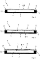
- FIGS. 1 to 7 show various embodiments of a fluid-tight packaging 1 according to the invention, which has a packaging container 2 and a packaging container 2 fluid-tightly closing closure member 3, each without arranged in a cavity 4 of the packaging container 2 filling material. However, this is received in the fluid-tight connection of the closure part 3 with the packaging container 2 in the cavity 4.
- Each of the packaging containers 2 of the various embodiments has a connection area 5 for the closure part 3.
- Each of the closure parts 3 has a connection region 6 assigned to the connection region 5 of the packaging container 2.
- the connection region 5 and the connection region 6 are assigned to one another and accordingly preferably have an identical shape and size.
- the connection region 5 of the packaging container 2 completely surrounds a supply / removal opening 7 for the contents to be closed with the closure part 3.
- the closure part 3 and the packaging container 2 are integrally connected to one another by means of laser transmission welding.
- the welding operation is carried out by means of a linear or planar laser beam, the laser light acting on the closure part 3 from the side facing away from the packaging container 2.
- d. H. Next to the connecting portion 6, the shutter member 3 passes and is acted upon by the supply / discharge port 7, and / or acts directly on the packaging container 2 in a surrounding portion around the connecting portion 5 past the shutter member 3, a reflection layer 8 is provided on the container Packing container 2 and / or the closure part 3 is arranged, which eliminates the connection region 5 of the packaging container 2 and the connecting portion 6 of the closure part 3.
- the shadow mask 9 shadows the supply / removal opening 7 of the packaging container 2 or the surface of the packaging container 2 not overlapped by the closure part 3 from laser radiation.
- the in the FIGS. 1 to 3 illustrated packaging 1 have a packaging container 2, which is cup-shaped with a circumferential collar 10 which forms the connection region 5 of the packaging container 2.
- the packaging container 2 is made of a laser light absorbing plastic material board made deep-drawn.
- the closure part 3 in the Figures 1 and 2 illustrated embodiments of a laser light permeable planar plastic film formed.
- the closure part 3 is integrally connected to the collar 10 of the packaging container 2 with a peripheral edge 11 which forms the connection region 6.
- the closure part 3 is not as in the embodiments of FIG. 1, 2 formed by a single-layer plastic film. Instead, the closure part 3 is formed in two layers, wherein the plastic composite film is laminated to a paper or cardboard blank.
- the reflection layer 8 formed in accordance with the size of the supply / discharge port 7 completely covers the cavity 4, respectively. It leaves only the edge 11 of the closure part 3 free.
- the reflection layer 8 is arranged on the side of the closure part 3 facing away from the packaging container 2, in which FIG. 2 on the packaging container 2 facing side of the closure part. 3
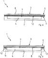
- the embodiments of the packaging according to FIGS. 4 and 5 differ from those in the FIGS. 1 to 3 illustrated embodiments in that the packaging container 2 is made of laser light-permeable plastic material and the closure part 3 is formed as a multilayer plastic film.
- the closure part 3 is also designed to be transparent to laser light.
- an absorption layer 12 is arranged between the packaging container 2 and the closure part 3.
- the absorption layer 12 is in each case applied to the side of the closure part 3 facing the packaging container 2 and extends according to FIG FIG. 4 over the entire surface of the closure part 3 and in the FIG. 5 only in the region of the connecting region 6 of the closure part 3. According to the FIG.
- the reflective layer 8 which engages over the cavity 4 of the packaging container 2, on the side facing away from the packaging container 2, the closure part 3 is arranged.
- the reflection layer 8 is arranged on the side of the closure part 3 facing the packaging container 2.
- the packaging container 2 is formed substantially closed and has only on the top of a small feed / discharge opening 7.
- the closure part 3 is the closure part 3 as a ripper with a gripping bottle and in the FIG. 7 designed as a spout with a lid, not shown in the drawing.
- the packaging container 2 is made entirely of plastic material or of a plastic coated cardboard or aluminum material. In particular, it is laser-opaque and laser-absorbing.
- the closure part 3 is made of a plastic material permeable to laser light.
- an absorption layer 12 is arranged in each case, which completely encompasses and / or engages over the supply / removal opening 7.
- the absorption layer 12 extends in particular as far as the connection region 5 of the packaging container 2 and the connection region 6 of the closure part 3. It encloses the supply / removal opening 7 completely.
- the absorption layer 12 is applied to the packaging container 2, preferably printed.
- the packaging container 2 has a reflection layer 8 which extends around the closure part 3 and encloses the absorption layer 12.
- the reflection layer 8 is preferably printed on the packaging container 2.
Description
- Die Erfindung betrifft ein Verfahren zum fluiddichten Verbinden eines Verschlussteils mit einem Verpackungsbehälter einer fluiddichten Verpackung mittels Laserdurchstrahlschweißen, wobei der Verpackungsbehälter Kunststoffmaterial zumindest als äußere Schichtlage in einem Anbindungsbereich für das Verschlussteil aufweist, der eine mit dem Verschlussteil zu verschließende Zuführ-/Entnahmeöffnung für ein Füllgut vollständig umgreift und wobei das Verschlussteil wenigstens an einem dem Anbindungsbereich des Verpackungsbehälters zugeordneten Verbindungsbereich Kunststoffmaterial zumindest als Beschichtung aufweist, wobei das Verschlussteil und der Verpackungsbehälter vorzugsweise mit Füllgut gefüllt bereitgestellt und das Verschlussteil mit dem Verbindungsbereich auf den Anbindungsbereich des Verpackungsbehälters aufgesetzt wird, der Verpackungsbehälter und das Verschlussteil mit einem linienförmigen oder flächenhaften energiereichen Laserstrahls bestrahlt und eine stoffschlüssige Verbindung des Verbindungsbereiches des Verschlussteils mit dem Anbindungsbereich des Verpackungsbehälters durch aneinander Pressen hergestellt wird.
- Die Erfindung betrifft außerdem eine Verpackung für feste, rieselfähige, pastöse oder flüssige Füllstoffe, mit einem Verpackungsbehälter der einen Hohlraum für die Füllstoffe aufweist, und mit einem den Hohlraum Fluiddicht verschließenden Verschlussteil, wobei der Verpackungsbehälter Kunststoffmaterial zumindest als äußere Schichtlage in einem Anbindungsbereich für das Verschlussteil aufweist, der eine mit dem Verschlussteil zu verschließende Zuführ-/Entnahmeöffnung für das Füllgut vollständig umgreift und wobei das Verschlussteil wenigstens an einem dem Anbindungsbereich des Verpackungsbehälters zugeordneten Verbindungsbereich Kunststoffmaterial zumindest als Beschichtung aufweist, und das Verschlussteil mit dem Verpackungsbehälter mittels Laserdurchstrahlschweißen stoffschlüssig verbunden ist.
- Das Verschweißen von Vollkunststoffteilen und/oder kunststoffbeschichteten Teilen miteinander, unter Einwirkung eines energiereichen Laserstrahls, ist aus dem Stand der Technik allgemein bekannt. Bei einem solchen Verfahren wird ein erstes Teil mit einem zweiten Teil durch Aufschmelzen deren Oberfläche in einem Anlagebereich unter gleichzeitiger Krafteinwirkung unter Ausbildung einer Schweißnaht stoffschlüssig verbunden. Die Energie zum lokalen Aufschmelzen des ersten und des zweiten Teils wird durch den Laserstrahl zur Verfügung gestellt, wobei eines der Teile aus einem Material besteht, welches die Energie des Laserstrahls nicht oder nur schwach absorbiert, und das andere Teil aus einem Material gefertigt ist, welches die Energie des Laserstrahls stark absorbiert. Beispielhaft wird auf die Druckschriften
DE 101 31 430 A1 undDE 10 2009 037 404 B4 verwiesen. - Zudem ist aus der
EP 1 911 677 A1 ein Verfahren zum Herstellen einer hermetisch abgedichteten Verpackung für Getränke oder Nahrungsmittel bekannt, bei dem ein Behälterkörper eines Verpackungsbehälters und ein an dem Behälterkörper angeordneter Deckel als Verschlussteil für den Verpackungsbehälter im Laserschweißverfahren zum Erzielen eines luftdichten Zustandes dichtend miteinander verbunden werden. Während der Verpackungsbehälter kontinuierlich auf einer Förderstrecke fortbewegt wird, wird der Behälterkörper mit an dem Behälterkörper angeordnetem Deckel für eine Zeitdauer mit Laserlicht bestrahlt, während der sich der Behälter in einen spezifischen Positionsbereich einer Verpackungsmaschine befindet. Dabei wird der vorgesehene Schweißbereich mit einem von einem Strahlformungselement ringförmig geformten Laserstrahl simultan mit Laserlicht beaufschlagt. Das Strahlformungselement ist spezifisch für die zu erzeugende ringförmige Schweißnaht eines Behältertyps ausgebildet. Wechselt der Behältertyp, so ist in der Regel ein Austausch oder zumindest eine Anpassung des Strahlformungselementes notwendig. Weiterer Nachteil bei dem bekannten Verfahren ist, dass der ringförmige Laserstrahl dem geförderten Verpackungsbehälter folgen muss, um einen ausreichenden Energieübertrag auf den Behälterkörper und/oder den Deckel zu gewährleisten. Dazu muss der Laserkopf mit der Transportgeschwindigkeit des gefüllten Verpackungsbehälters dem Behälter nachgeführt und nach der Verschweißung des Deckels mit dem Behälterkörper erneut zum nächsten Verpackungsbehälter verfahren werden. Damit geht wertvolle Prozesszeit verloren, die eine unerwünschte Kapazitätsminderung der Verpackungsmaschine bewirkt. - Des Weiteren ist aus der
JP 2013-203026 A - Ausgehend von diesem Stand der Technik liegt der Erfindung die Aufgabe zugrunde, ein vereinfachtes Herstellungsverfahren zum fluiddichten Verbinden eines Verschlussteils mit einem Verpackungsbehälter mittels Laserdurchstrahlschweißen vorzuschlagen, bei dem der Laserkopf und auch der Laserstrahl ortsfest sind und der Laserstrahl auch bei unterschiedlich ausgebildetem Verschlussteil und Verpackungsbehälter in seiner Form und Lage unverändert beibehalten werden kann. Weitere Aufgabe der Erfindung ist, eine Verpackung mit einer mit dem Verpackungsbehälter fluiddicht verbundenen Verschlussteil bereitzustellen, das die Anwendung des vorgeschlagenen Herstellungsverfahrens ermöglicht und entsprechend hergestellt ist.
- Diese Aufgabe wird erfindungsgemäß durch ein Verpackungsverfahren bzw. eine Verpackung mit den Merkmalen der beiden nebengeordneten unabhängigen Patentansprüche 1 und 11 gelöst. Weitere vorteilhafte Ausgestaltungen sind den jeweils rückbezogenen Patentansprüchen zu entnehmen.
- Das erfindungsgemäße Verfahren zum fluiddichten Verbinden eines Verschlussteils mit einem Verpackungsbehälter im Laserdurchstrahlschweißverfahren setzt voraus, dass der Verpackungsbehälter Kunststoffmaterial zumindest als äußere Schichtlage in einem Anbindungsbereich für das Verschlussteil und das Verschlussteil wenigstens an einem dem Anbindungsbereich des Verpackungsbehälters zuordneten Verbindungsbereich Kunststoffmaterial zumindest als Beschichtung aufweist. Der Kerngedanke der Erfindung besteht nun darin, den Verpackungsbehälter und das Verschlussteil über den Anbindungsbereich bzw. den Verbindungsbereich seitlich deutlich hinausgehend mittels eines linienförmigen oder flächenhaften energiereichen Laserstrahls mit Laserlicht zu beaufschlagen, ohne den Verpackungsbehälter oder das Verschlussteil außerhalb des Anbindungsbereiches des Verpackungsbehälters und/oder des Verbindungsbereiches der Verschlussteils übermäßig zu erhitzen und damit frei von möglichen Beschädigungen zu halten. Dabei soll auch eine Bestrahlung des in dem Verpackungsbehälter aufgenommenen Füllgutes aus den gleichen Gründen verhindert werden. Außerhalb des Anbindungsbereiches und/oder des Verbindungsbereiches bedeutet in diesem Zusammenhang, dass der Laserstrahl auf Umgebungsabschnitte des Verpackungsbehälters und/oder Verschlussteils gerichtet wird, die von dem Anbindungsbereich und/oder Verbindungsbereich eingeschlossen sind bzw. den Anbindungsbereich und/oder den Verbindungsbereich umgreifen.
- Während des Laserdurchstrahlschweißens wird der Laserstrahl dabei relativ zu dem Anbindungsbereich bzw. Verbindungsbereich bewegt, wobei insbesondere der Laserstrahl ortsfest ist und in seiner Form unverändert bleibt und der Verpackungsbehälter mit dem Verschlussteil gegenüber dem Laserstrahl bewegt wird. Um Beschädigungen oder Veränderungen des Verpackungsbehälters, des Verschlussteils und/oder von in einem Hohlraum des Verpackungsbehälters angeordnetem Füllgut auszuschließen, erfolgt die Beaufschlagung des Anbindungsbereiches des Verpackungsbehälters bzw. des Verbindungsbereiches des Verschlussteils mit dem energiereichen Laserlicht über eine Schattenmaske, die den Laserstrahl nur auf den Anbindungsbereich bzw. den Verbindungsbereich fallen lässt. Die Schattenmaske für den Laserstrahl wird für den Verbindungsvorgang von Verpackungsbehälter und Verschlussteil direkt angrenzend an den Anbindungsbereich bzw. Verbindungsbereich angeordnet. Sie ist mit dem Verpackungsbehälter oder dem Verschlussteil verbunden und Teil des Verpackungsbehälters oder des Verschlussteils. Sie wird von einer Beschichtung des Verpackungsbehälters bzw. des Verschlussteils gebildet, die stoffschlüssig aufgebracht ist. Die Schattenmaske überdeckt den Verpackungsbehälter und/oder das Verschlussteil zumindest teilweise außerhalb des Anbindungsbereiches des Verpackungsbehälters bzw. des Verbindungsbereiches des Verschlussteils und schützt damit diejenigen Stellen des Verpackungsbehälters mit Verschlussteils vor einfallendem Laserlicht, die nicht erhitzt werden sollen. Der Anbindungsbereiches des Verpackungsbehälters und der Verbindungsbereiches des Verschlussteils davon ausgenommen, da dort eine Erhitzung des Kunststoffmaterials zur dessen Aufschmelzung für die Ausbildung einer Schweißnaht notwendig ist. Die kann auch die mit dem Verschlussteil zu verschließende Zuführ-/Entnahmeöffnung des Verpackungsbehälters für das Füllgut vollständig abdecken.
- Das Verbinden des Verschlussteils mit dem Verpackungsbehälters im Laserdurchstrahlschweißverfahren erfordert nach dem Aufschmelzen des Anbindungsbereiches des Verpackungsbehälters und/oder des Verbindungsbereiches des Verschlussteils mittels des energiereichen Laserstrahls eine Krafteinwirkung auf diese Teile, die das Verschlussteil gegen den Verpackungsbehälter presst, bis die gebildete Kunststoffmaterialschmelze abgekühlt und erstarrt ist. Die erforderliche Anpresskraft kann mit allen geeigneten, dem Fachmann bekannten Maßnahmen bewirkt werden. Der Andruck des Verschlussteils kann beispielsweise mittels einem Rad, vorzugsweise einem segmentierten Rad, oder einer keilförmig zulaufenden Schiene erfolgen, die einen Niederhalter bilden. Es ist von Vorteil, den Niederhalter in einem transparenten und damit für Laserlicht durchlässigen Material auszuführen.
- Erfindungsgemäß wird der Verpackungsbehälter außerhalb des Anbindungsbereiches und/oder das Verschlussteil außerhalb des Verbindungsbereiches mit einer Laserlicht rückstrahlenden Reflexionsschicht beschichtet.
- Bei dem vorgeschlagenen Verfahren sind die folgenden Schritte vorgesehen:
- Beschichten des Verpackungsbehälters außerhalb des Anbindungsbereiches und/oder des Verschlussteils außerhalb des Verbindungsbereiches mit einer Laserlicht rückstrahlenden Reflexionsschicht;
- Bereitstellen des mit Füllgut gefüllten Verpackungsbehälters und Aufsetzen des Verschlussteils mit dem Verbindungsbereich auf den Anbindungsbereich des Verpackungsbehälters;
- Bestrahlen des Verpackungsbehälters und des Verschlussteils mit einem linienförmigen oder flächenhaften energiereichen Laserstrahl; und
- Herstellen einer stoffschlüssigen Verbindung des Verbindungsbereiches des Verschlussteils mit dem Anbindungsbereich des Verpackungsbehälters durch aneinander Pressen.
- Dabei kann die Beschichtung des Verpackungsbehälters bzw. des Verschlussteils durch direktes Auftragen einer Materialschicht oder durch Applizieren eines beschichteten Aufklebers erfolgen. Die Laserlicht rückstrahlende Reflexionsschicht ist vorzugsweise stoffschlüssig direkt oder indirekt mit dem Verpackungsbehälter bzw. dem Verschlussteil verbunden. Es ist selbstverständlich, dass für das an sich bekannte Laserdurchstrahl-Maskenschweißverfahren der Verpackungsbehälter oder das Verschlussteil Laserlicht absorbierendes Kunststoffmaterial zumindest im Anbindungsbereich bzw. Verbindungsbereich aufweist und die jeweils andere Komponente im Wesentlichen für das Laserlicht durchlässig ist, oder dass sowohl der Verpackungsbehälter wie auch das Verschlussteil nicht Laserlicht absorbierend ausgeführt sind und eine Laserlicht absorbierende Kunststofffolie als Zwischenschicht verwendet wird.
- Vorzugsweise wird bei dem vorgeschlagenen Verfahren zum fluiddichten Verbinden eines Verschlussteils mit einer Verpackungsbehälter, der Verpackungsbehälter mit dem aufgesetzten Verschlussteil gegenüber einem ortsfesten Laserstrahl kontinuierlich bewegt. Dabei können abhängig von der Breite des Laserstrahls mehrere nebeneinander angeordnete Verpackungsbehälter mit Verschlussteil gleichzeitig mit Laserlicht beaufschlagt werden. Insbesondere können ein oder mehr derartige Verpackungsbehälter mit Verschlussteilen unabhängig von ihrer Größe und Form und von der Geometrie des Anbindungsbereiches des Verpackungsbehälters bzw. des Verbindungsbereiches des Verschlussteils auf einfache Weise verschweißt werden.
- Bei einer weiteren bevorzugten Ausführungsform des erfindungsgemäßen Verfahrens wird der Laserstrahl synchronisiert mit der Bewegungsgeschwindigkeit des Verpackungsbehälters mit Verschlussteil ein- und ausgeschaltet. Dies bewirkt, dass nicht der gesamte Verpackungsbehälter mit dem Laserstrahl bestrahlt wird, sondern nur des Anbindungsbereiches des Verpackungsbehälters bzw. des Verbindungsbereiches des Verschlussteils sowie derjenige Teil des Verpackungsbehälters und/oder des Verschlussteils außerhalb des Anbindungsbereiches bzw. des Verbindungsbereiches partiell, an dem die das Laserlicht rückstrahlende Reflexionsschicht angeordnet ist. Die Fläche der Reflexionsschicht kann somit gegenüber den Abmaßen der Verpackungsbehälter kleiner gehalten werden, so dass noch genügend Fläche für artikelspezifische oder firmeneigene Beschriftungen und/oder Abbildungen zur Verfügung steht.
- Die Reflexionsschicht weist in jedem Fall eine helle Farbe auf, damit das Laserlicht nicht absorbiert wird und ist somit in der Regel unauffällig. Sie stört das Erscheinungsbild der fertiggestellten Verpackung kaum oder nicht. Die Reflexionsschicht wird vorzugsweise aufgedruckt, wobei insbesondere reflektierende Farbstoffe verwendet werden. Die Reflexionsschicht kann schon bei der Herstellung des Verpackungsbehälters bzw. des Verschlussteils oder auch später als Beschichtung aufgebracht werden. Ein Bedrucken des Verpackungsbehälters bzw. des Verschlussteils ist in der Regel ohnehin vorgesehen, so dass die Aufbringung der Reflexionsschicht in einem gemeinsamen Arbeitsgang kostengünstig erfolgen kann.
- Bei einer anderen bevorzugten Verfahrensform wird für den Verpackungsbehälter Laserlicht absorbierendes und für das Verschlussteil Laserlicht durchlässiges Kunststoffmaterial verwendet, wobei die Reflexionsschicht auf der dem Verpackungsbehälter zugewandten oder abgewandten Seite des Verschlussteils angeordnet wird. Eine andere begünstigte Verfahrensform sieht vor, dass für den Verpackungsbehälter und das Verschlussteil Laserlicht durchlässiges Kunststoffmaterial verwendet wird, wobei die Reflexionsschicht auf der dem Verpackungsbehälter abgewandten Seite des Verschlussteils angeordnet wird und auf der dem Verpackungsbehälter zugewandten Seite des Verschlussteils zumindest im Verbindungsbereich eine Laserlicht absorbierende Absorptionsschicht angeordnet wird.
- Bei einer weiteren anderen bevorzugten Verfahrensform ist vorgesehen, dass für den Verpackungsbehälter und das Verschlussteil Laserlicht durchlässiges Kunststoffmaterial verwendet wird, wobei die Reflexionsschicht auf der dem Verpackungsbehälter abgewandten Seite des Verschlussteils angeordnet wird, und an dem Anbindungsbereich des Verpackungsbehälters und/oder an dem Verbindungsbereich des Verschlussteils ein Laserlicht absorbierende Absorptionsschicht angeordnet wird.
- Die Absorptionsschicht wird vorzugsweise aufgedruckt. Dazu werden insbesondere Laserlicht absorbierende Farbstoffe verwendet.
- Damit sind alle beim Laserdurchstrahlschweißverfahren möglichen Konfigurationen abgedeckt. Die Beaufschlagung des Anbindungsbereiches des Verpackungsbehälters oder des Verbindungsbereiches des Verschlussteiles mit Laserlicht erfolgt in allen vorstehend angegebenen Fällen, indem der Laserstrahl auf diejenige Komponente, Verpackungsbehälter oder Verschlussteil, gerichtet wird, der für Laserlicht durchlässig ausgebildet ist und somit das Laserlicht nicht absorbiert.
- Das vorgeschlagene erfindungsgemäße Verfahren ist geeignet zum fluiddichten Verschließen eines einen Hohlraum für die Aufnahme von Füllgut aufweisenden Verpackungsbehälters mittels eines Verschlussteils, der vollständig aus Kunststoff hergestellt ist oder außen zumindest eine Kunststoffschicht trägt und dessen Kunststoffmaterial laserschweißbar ist. Der Verpackungsbehälter kann warm geformt, d. h. tiefgezogen bzw. spritzgegossen oder aus einer KunststoffVerbundfolie gefaltet sein, die an geeigneten Kanten verklebt oder verschweißt ist. Gleiches gilt für das Verschlussteil. Als Verschlussteil kann zudem auch eine ebene unstrukturierte und damit flache Kunststofffolie verwendet werden. Die Form, Größe, Farbe, Aufmachung und Materialart bzw. Materialkombination des Verpackungsbehälters und des Verschlussteils sind beliebig wählbar, solange die Kunststoffmaterialen kompatibel sind und eine Kunststoffschweißverbindung zulassen.
- Mit dem vorgeschlagenen Verfahren können insbesondere mit Füllgut gefüllte Verpackungsbehälter mittels des Verschlussteils einfach, schnell und sicher fluiddicht verschlossen werden. Vorteil des erfindungsgemäßen Verfahrens ist, dass die Schattenmaske zum einen kostengünstig herstellbar ist, und zum anderen nicht auf oder über den Verpackungsbehälter mit dem Verschlussteil für den Schweißvorgang anzuordnen ist. Sie muss zudem nicht durch eine spezielle externe Vorrichtung positioniert, mit dem Verpackungsbehälter mit daran angeordneten Verschlussteilen mitbewegt und von diesen wieder entfernt werden.
- Bei der erfindungsgemäßen fluiddichten Verpackung für feste, rieselfähige, pastöse oder flüssige Füllstoffe, mit einem Verpackungsbehälter, der einen Hohlraum für die Füllstoffe aufweist und mit einem den Hohlraum fluiddicht verschließenden Verschlussteil, Verpackungsbehälter mittels Laserdurchstrahlschweißen verbunden ist, bei dem das Verschlussteil mit dem Verpackungsbehälter mittels Laserdurchstrahlschweißen verbunden oder verbindbar ist, weist der Verpackungsbehälter außerhalb des Anbindungsbereiches und/oder das Verschlussteil außerhalb des Verbindungsbereiches eine Laserlicht rückstrahlende Reflexionsschicht auf. Die reflektierende Beschichtung kann eine metallische Beschichtung sein, die das Licht direkt zurückreflektiert oder ein weißes, insbesondere mineralisches Pigment, dass das Laserlicht größtenteils diffus zurückstreut. Der Verpackungsbehälter weist zumindest als äußere Schichtlage in einem Anbindungsbereich für das Verschlussteil und das Verschlussteil wenigstens an einem dem Anbindungsbereich des Verpackungsbehälters zugeordneten Verbindungsreich Kunststoffmaterial zumindest als Beschichtung auf, die kompatibel miteinander ausgewählt sind und somit im Laserschweißverfahren stoffschlüssig miteinander verbunden werden können.
- Bei einer bevorzugten Ausführungsform der erfindungsgemäßen ist zumindest an dem Anbindungsbereich des Verpackungsbehälters oder dem Verbindungsbereich des Verschlussteils eine Laserlicht absorbierende Absorptionsschicht angeordnet, die insbesondere dann wirksam ist, wenn sowohl der Verpackungsbehälter wie auch das Verschlussteil aus für Laserlicht transparenten Kunststoffmaterial hergestellt sind.
- Der Verpackungsbehälter kann beispielsweise eine aus einer stärkeren Kunststofffolie hergestellte tiefgezogene Schale mit einem umlaufenden Rand als Anbindungsbereich für ein zumindest im Bereich der Zuführ-/Entnahmeöffnung für das Füllgut eben ausgebildetes Verschlussteil in Form einer unstrukturierten oder geringfügig tiefgezogenen Kunststofffolie mit einem außen umlaufenden dem Anbindungsbereich des Verpackungsbehälters zugeordneten Verbindungsbereich sein. Der Verpackungsbehälter kann zum Beispiel auch ein innen und außen kunststoffbeschichteter gefalteter dichter Getränkekarton sein, mit einer Zuführ-/Entnahmeöffnung, die mittels eines Verschlussteils in Form eines Kunststoffspritzteils, das einen Ausgießer mit einem Schraubdeckel aufweist, fluiddicht verschließbar ist. Ein solcher Getränkekarton weist um die Zuführ-/Entnahmeöffnung herum einen sich ringförmig geschlossen erstreckenden Anbindungsbereich für das Verschlussteil auf, das an einem Fuß des Ausgießers mit einen dem Anbindungsbereich des Verpackungsbehälters zugeordneten Verbindungsbereich ausgebildet ist.
- Beide vorstehend beispielhaft genannten Ausführungsbeispiele der Verpackung weisen eine aufgedruckte oder auflaminierte rückstrahlende Reflexionsschicht für das Laserlicht eines linienförmigen oder flächenhaften energiereichen Laserstrahls auf, die außerhalb des Anbindungsbereichs des Verpackungsbehälters bzw. des Verbindungsbereichs des Verschlussteils verläuft. Bei entsprechender Größe der Reflexionsschicht ist eine Beeinflussung des Materials des Verpackungsbehälters bzw. des in dem Hohlraum des Verpackungsbehälters aufgenommenen Füllgutes durch den Laserstrahl weitgehend ausgeschlossen.
- Das erfindungsgemäße vorstehend beschriebene Verfahren kann auch für die Fertigstellung einer derartigen Getränkekartonverpackung verwendet werden, bei der der gefüllte Getränkekarton mittels des den Schraubverschluss tragenden Ausgießers fluiddicht verschlossen wird. Dazu wird bei einer bevorzugten Ausführungsform der Erfindung der Verpackungskarton zuerst im Verbindungsbereich mit einer Laserlicht absorbierenden Absorptionsschicht im Anbindungsbereich beschichtet. Zudem wird der Verpackungskarton mit einer die Absorptionsschicht umschließenden laserlichtrückstrahlenden Reflexionsschicht noch zusätzlich beschichtet. Dann wird ein vorzugsweise aus für Laserlicht durchlässigen Kunststoffmaterial hergestellte Ausgießer mit Schraubverschluss mit seinem Verbindungsbereich auf den Anbindungsbereich des Verpackungskartons aufgesetzt und die Absorptionsschicht mit Laserlicht mittels einem linienförmigen oder flächenhaften Laserstrahls beaufschlagt, wobei die aufgebrachte Reflexionsschicht den Laserstrahl von dem Getränkekarton zumindest in einem Bereich um den Ausgießer fern hält, so dass die Oberfläche des Getränkekartons dort nicht verändert wird.
- Nachfolgend wird die Erfindung anhand mehrerer in der Zeichnung dargestellter Ausführungsbeispiele näher erläutert. Weitere Merkmale der Erfindung ergeben sich aus der folgenden Beschreibung des Ausführungsbeispiels der Erfindung in Verbindung mit den Ansprüchen und den beigefügten Figuren. Die einzelnen Merkmale der Erfindung können für sich allein oder zu mehreren bei unterschiedlichen Ausführungsformen der Erfindung verwirklicht sein. Es zeigen:
- Figur 1
- eine erfindungsgemäße Verpackung mit einem Laserlicht absorbierenden Verpackungsbehälter und einem Laserlicht durchlässigen Verschlussteil, wobei die Reflexionsschicht oben an dem Verschlussteil angeordnet ist;
- Figur 2
- eine andere erfindungsgemäße Verpackung mit einem Laserlicht absorbierenden Verpackungsbehälter und einem Laserlicht durchlässigen Verschlussteil, wobei die Reflexionsschicht unten an dem Verschlussteil angeordnet ist;
- Figur 3
- eine weitere erfindungsgemäße Verpackung mit einem Laserlicht absorbierenden Verpackungsbehälter und einem Laserlicht durchlässigen Verschlussteil, wobei das Verschlussteil zweilagig ausgebildet und die Reflexionsschicht oben auf dem Verschlussteil angeordnet ist;
- Figur 4
- eine erfindungsgemäße Verpackung mit einem Laserlicht durchlässigen Verpackungsbehälter und einem ebensolchen Verschlussteil, wobei das Verschlussteil zweilagig ausgebildet ist und die Reflexionsschicht oben auf dem Verschlussteil und unten an dem Verschlussteil eine Absorptionsschicht für das Laserlicht angeordnet ist.
- Figur 5
- eine erfindungsgemäße Verpackung mit einem Laserlicht durchlässigen Verpackungsbehälter und ein ebensolches Verschlussteil, wobei die Reflexionsschicht oben auf dem Verschlussteil angeordnet ist und das Verschlussteil in seinem Verbindungsbereich unten örtlich eine Absorptionsschicht für das Laserlicht aufweist;
- Figur 6
- eine weitere erfindungsgemäße Verpackung mit einem Laserlicht absorbierenden im Wesentlichen geschlossenen Verpackungsbehälter und einem Laserlicht durchlässigen Verschlussteil in Form eines Aufreißers, wobei der Verpackungsbehälter im Bereich des Verschlussteils eine Absorptionsschicht und eine die Absorptionsschicht umgreifende Reflexionsschicht für das Laserlicht aufweist; und
- Figur 7
- eine andere erfindungsgemäße Verpackung, die ähnlich der der
Figur 6 ausgebildet ist, wobei der Aufreißer durch einen Ausgießer ersetzt ist. - Die
Figuren 1 bis 7 zeigen verschiedene Ausführungsformen einer erfindungsgemäßen fluiddichten Verpackung 1, die einen Verpackungsbehälter 2 und ein den Verpackungsbehälter 2 fluiddicht verschließendes Verschlussteil 3 aufweist, jeweils ohne in einem Hohlraum 4 des Verpackungsbehälters 2 angeordneten Füllgut. Dieses ist jedoch beim fluiddichten Verbinden des Verschlussteils 3 mit dem Verpackungsbehälter 2 in dem Hohlraum 4 aufgenommen. Jeder der Verpackungsbehälter 2 der verschiedenen Ausführungsbeispiele weist einen Anbindungsbereich 5 für das Verschlussteil 3 auf. Jedes der Verschlussteile 3 weist einen dem Anbindungsbereich 5 des Verpackungsbehälters 2 zugeordneten Verbindungsbereich 6 auf. Der Anbindungsbereich 5 und der Verbindungsbereich 6 sind einander zugeordnet und weisen dementsprechend vorzugsweise eine identische Form und Größe auf. Der Anbindungsbereich 5 des Verpackungsbehälters 2 umgreift eine mit dem Verschlussteil 3 zu verschließende Zuführ-/Entnahmeöffnung 7 für das Füllgut vollständig. - Das Verschlussteil 3 und der Verpackungsbehälter 2 sind mittels Laserdurchstrahlschweißen miteinander stoffschlüssig verbunden. Der Schweißvorgang wird mittels eines linienförmigen oder flächenhaften Laserstrahls ausgeführt, wobei das Laserlicht das Verschlussteil 3 von der dem Verpackungsbehälter 2 abgewandten Seite her beaufschlagt. Um zu verhindern, dass das Laserlicht auf das in dem Hohlraum 4 aufgenommene Füllgut fällt, d. h. neben dem Verbindungsbereich 6 das Verschlussteil 3 passiert und durch die Zuführ-/Entnahmeöffnung 7 hindurch beaufschlagt, und/oder direkt auf den Verpackungsbehälter 2 in einem Umgebungsabschnitt um den Anbindungsbereich 5 herum, an dem Verschlussteil 3 vorbei, einwirkt, ist eine Reflexionsschicht 8 an dem Verpackungsbehälter 2 und/oder dem Verschlussteil 3 angeordnet, die den Anbindungsbereich 5 des Verpackungsbehälters 2 sowie den Verbindungsbereich 6 des Verschlussteils 3 ausspart. Die Reflexionsschicht 8, die als Schattenmaske 9 für den in den Figuren nicht dargestellten Laserstrahl wirkt, reicht dabei direkt außen bis an den Anbindungsbereich 5 des Verpackungsbehälters 2 oder innen an den Verbindungsbereich 6 des Verschlussteils 3 heran. Die Schattenmaske 9 schattet die Zuführ-/Entnahmeöffnung 7 des Verpackungsbehälters 2 oder die nicht von dem Verschlussteil 3 übergriffenen Fläche des Verpackungsbehälters 2 vor Laserstrahlung ab.
- Die in den
Figuren 1 bis 3 dargestellten Verpackungen 1 weisen einen Verpackungsbehälter 2 auf, der schalenförmig mit einem umlaufenden Bund 10 ausgebildet ist, der den Anbindungsbereich 5 des Verpackungsbehälters 2 bildet. Der Verpackungsbehälter 2 ist aus einer Laserlicht absorbierenden Kunststoffmaterialtafel tiefgezogen hergestellt. Demgegenüber ist das Verschlussteil 3 der in denFiguren 1 und 2 dargestellten Ausführungsbeispiele von einer Laserlicht durchlässigen planen Kunststofffolie gebildet. Das Verschlussteil 3 ist mit einem umlaufenden Rand 11, der den Verbindungsbereich 6 bildet, mit dem Bund 10 des Verpackungsbehälters 2 stoffschlüssig verbunden. Bei der in derFigur 3 dargestellten Ausführungsform der Verpackung 1 wird das Verschlussteil 3 nicht wie bei dem Ausführungsformen vonFigur 1, 2 von einer einlagigen Kunststofffolie gebildet. Stattdessen ist das Verschlussteil 3 zweilagig ausgebildet, wobei die Kunststoffverbundfolie auf einen Papier- oder Kartonzuschnitt auflaminiert ist. Gemäß den Abbildungen 1 bis 3 deckt die Reflexionsschicht 8, die entsprechend der Größe der Zuführ-/Entnahmeöffnung 7 ausgebildet ist, jeweils den Hohlraum 4 vollkommen ab. Sie lässt nur den Rand 11 des Verschlussteils 3 frei. In denFiguren 1 und 3 ist die Reflexionsschicht 8 auf der dem Verpackungsbehälter 2 abgewandten Seite des Verschlussteils 3 angeordnet, bei derFigur 2 auf der dem Verpackungsbehälter 2 zugewandten Seite des Verschlussteils 3. - Die Ausführungsformen der Verpackungen gemäß
Figur 4 und 5 unterscheiden sich von den in denFiguren 1 bis 3 dargestellten Ausführungsbeispielen dadurch, dass der Verpackungsbehälter 2 aus Laserlicht durchlässigem Kunststoffmaterial hergestellt ist und das Verschlussteil 3 als Multilayer-Kunststofffolie ausgebildet ist. Das Verschlussteil 3 ist ebenfalls für Laserlicht durchlässig ausgeführt. Demzufolge ist eine Absorptionsschicht 12 zwischen dem Verpackungsbehälter 2 und dem Verschlussteil 3 angeordnet. Die Absorptionsschicht 12 ist jeweils auf der dem Verpackungsbehälter 2 zugewandten Seite des Verschlussteils 3 aufgebracht und erstreckt sich gemäß derFigur 4 über die gesamte Fläche des Verschlussteils 3 und bei derFigur 5 nur im Bereich des Verbindungsbereiches 6 des Verschlussteils 3. Gemäß derFigur 4 ist die Reflexionsschicht 8, die den Hohlraum 4 des Verpackungsbehälters 2 übergreift, auf der den Verpackungsbehälter 2 abgewandten Seite, des Verschlussteils 3 angeordnet. Demgegenüber ist bei derFigur 5 die Reflexionsschicht 8 auf der dem Verpackungsbehälter 2 zugewandten Seite des Verschlussteils 3 angeordnet. - Bei den in den
Figuren 6, 7 abgebildeten Ausführungsformen der erfindungsgemäßen Verpackung 1 ist der Verpackungsbehälter 2 im Wesentlichen geschlossen ausgebildet und weist lediglich auf der Oberseite eine kleine Zuführ-/Entnahmeöffnung 7 auf. In derFigur 6 ist das Verschlussteil 3 als Aufreißer mit einer Greifflasche und in derFigur 7 als Ausgießer mit einem in der Zeichnung nicht dargestellten Deckel ausgeführt. Der Verpackungsbehälter 2 ist vollständig aus Kunststoffmaterial hergestellt oder aus einem mit Kunststoff beschichtetem Karton- oder Aluminium-Material. Er ist insbesondere Laserlicht undurchlässig und Laserlicht absorbierend ausgeführt. Das Verschlussteil 3 ist demgegenüber aus einem Laserlicht durchlässigen Kunststoffmaterial hergestellt. Zwischen dem Verschlussteil 3 und dem Verpackungsbehälter 2 ist jeweils eine Absorptionsschicht 12 angeordnet, die die Zuführ-/Entnahmeöffnung 7 vollständig umgreift und/oder übergreift. Die Absorptionsschicht 12 reicht insbesondere bis hin zu dem Anbindungsbereich 5 des Verpackungsbehälters 2 und dem Verbindungsbereich 6 des Verschlussteils 3. Sie umschließt die Zuführ-/Entnahmeöffnung 7 vollständig. Die Absorptionsschicht 12 ist auf den Verpackungsbehälter 2 aufgebracht, vorzugsweise aufgedruckt. Zudem weist der Verpackungsbehälter 2 eine Reflexionsschicht 8 auf, die sich um das Verschlussteil 3 herum erstreckt und die Absorptionsschicht 12 einschließt. Die Reflexionsschicht 8 ist auf den Verpackungsbehälter 2 vorzugsweise aufgedruckt.
Claims (12)
- Verfahren zum fluiddichten Verbinden eines Verschlussteils (3) mit einem Verpackungsbehälter (2) einer fluiddichten Verpackung (1) mittels Laserdurchstrahlschweißen, wobei der Verpackungsbehälter (2) Kunststoffmaterial zumindest als äußere Schichtlage in einem Anbindungsbereich (5) für das Verschlussteil (3) aufweist, der eine mit dem Verschlussteil (3) zu verschließende Zuführ-/Entnahmeöffnung (7) für ein Füllgut vollständig umgreift und wobei das Verschlussteil (3) wenigstens an einem dem Anbindungsbereich (5) zugeordneten Verbindungsbereich (6) Kunststoffmaterial zumindest als Beschichtung aufweist, mit den folgenden Schritten:- Beschichten des Verpackungsbehälters (2) außerhalb des Anbindungsbereiches (5) und/oder des Verschlussteils (3) außerhalb des Verbindungsbereiches (6) mit einer Laserlicht rückstrahlenden Reflexionsschicht (8);- Bereitstellen des vorzugsweise mit Füllgut gefüllten Verpackungsbehälters (2) und Aufsetzen des Verschlussteils (3) mit dem Verbindungsbereich (6) auf den Anbindungsbereich (5) des Verpackungsbehälters (2);- Bestrahlen des Verpackungsbehälters (2) und des Verschlussteiles (3) mit einem linienförmigen oder flächenhaften energiereichen Laserstrahls;- Herstellen einer stoffschlüssigen Verbindung des Verbindungsbereiches (6) des Verschlussteils (3) mit dem Anbindungsbereich (5) des Verpackungsbehälters durch aneinander Pressen.
- Verfahren nach Anspruch 1, dadurch gekennzeichnet, dass der Verpackungsbehälter (2) mit dem aufgesetzten Verschlussteil (3) beim Laserdurchstrahlschweißen gegenüber einem ortsfesten Laserstrahl kontinuierlich bewegt wird.
- Verfahren nach Anspruch 2, dadurch gekennzeichnet, dass der Laserstrahl synchronisiert mit der Bewegung des Verpackungsbehälters (2) mit Verschlussteil (3) ein- und ausgeschaltet wird.
- Verfahren nach einem der vorstehenden Ansprüche, dadurch gekennzeichnet, dass die Reflexionsschicht (8) auf den Verpackungsbehälter (2) und/oder das Verschlussteil (3) aufgedruckt wird.
- Verfahren nach Anspruch 4, dadurch gekennzeichnet, dass für die Reflexionsschicht (8) reflektierende Farbstoffe verwendet werden.
- Verfahren nach einem der vorstehenden Ansprüche, dadurch gekennzeichnet, dass für den Verpackungsbehälter (2) Laserlicht absorbierendes und für das Verschlussteil (3) Laserlicht durchlässiges Kunststoffmaterial verwendet wird, wobei die Reflexionsschicht (8) auf der den Verpackungsbehälter (2) zugewandten oder abgewandten Seite des Verschlussteils (3) angeordnet wird.
- Verfahren nach einem der vorstehenden Ansprüche 1 bis 5, dadurch gekennzeichnet, dass für den Verpackungsbehälter (2) und das Verschlussteil (3) Laserlicht durchlässiges Kunststoffmaterial verwendet wird, wobei die Reflexionsschicht (8) auf der dem Verpackungsbehälter (2) abgewandten Seite des Verschlussteils (3) angeordnet wird und wobei auf der dem Verpackungsbehälter (2) zugewandten Seite des Verschlussteils (3) zumindest im Verbindungsbereich (6) eine Laserlicht absorbierende Absorptionsschicht (12) aufgebracht wird.
- Verfahren nach einem der vorstehenden Ansprüche 1 bis 5, dadurch gekennzeichnet, dass für den Verpackungsbehälter (2) und das Verschlussteil (3) Laserlicht durchlässiges Kunststoffmaterial verwendet wird, wobei die Reflexionsschicht (8) auf der dem Verpackungsbehälter (2) abgewandten Seite des Verschlussteils (3) angeordnet wird und an dem Anbindungsbereich (5) des Verpackungsbehälters (2) oder an dem Verbindungsbereich (6) des Verschlussteils (3) eine Laserlicht absorbierende Absorptionsschicht (12) aufgebracht wird.
- Verfahren nach Anspruch 7 oder 8, dadurch gekennzeichnet, dass die Absorptionsschicht (12) aufgedruckt wird,
- Verfahren nach Anspruch 9, dadurch gekennzeichnet, dass für die Absorptionsschicht (12) absorbierende Farbstoffe verwendet werden.
- Fluiddichte Verpackung (1) für feste, rieselfähige, pastöse oder flüssige Füllstoffe mit einem Verpackungsbehälter (2), der einen Hohlraum (4) für die Füllstoffe aufweist und mit einem den Hohlraum (4) fluiddicht verschließenden Verschlussteil (3), wobei der Verpackungsbehälter (2) Kunststoffmaterial zumindest als äußere Schichtlage in einem Anbindungsbereich (5) für das Verschlussteil (3) aufweist, der eine mit dem Verschlussteil (3) zu verschließende Zuführ-/Entnahmeöffnung (7) für das Füllgut vollständig umgreift, und wobei das Verschlussteil (3) wenigstens an einem dem Anbindungsbereich (5) des Verpackungsbehälters (2) zugeordneten Verbindungsbereich (6) Kunststoffmaterial zumindest als Beschichtung aufweist, und wobei das Verschlussteil (3) mit dem Verpackungsbehälter (2) mittels Laserdurchstrahlschweißen stoffschlüssig verbunden bzw. verbindbar ist, dadurch gekennzeichnet, dass der Verpackungsbehälter (2) außerhalb des Anbindungsbereiches (5) und/oder das Verschlussteil (3) außerhalb des Verbindungsbereiches (6) eine Laserlicht rückstrahlende Reflexionsschicht (8) aufweist.
- Verpackung nach Anspruch 11, dadurch gekennzeichnet, dass zumindest an dem Anbindungsbereich (5) des Verpackungsbehälters (2) oder an dem Verbindungsbereich (6) des Verschlussteils (3) eine Laserlicht absorbierende Absorptionsschicht (12) angeordnet ist.
Priority Applications (1)
| Application Number | Priority Date | Filing Date | Title |
|---|---|---|---|
| EP14172763.6A EP2957417B1 (de) | 2014-06-17 | 2014-06-17 | Verfahren zum fluiddichten Verbinden eines Verschlussteils mit einem Verpackungsbehälter und entsprechend hergestellte Verpackung |
Applications Claiming Priority (1)
| Application Number | Priority Date | Filing Date | Title |
|---|---|---|---|
| EP14172763.6A EP2957417B1 (de) | 2014-06-17 | 2014-06-17 | Verfahren zum fluiddichten Verbinden eines Verschlussteils mit einem Verpackungsbehälter und entsprechend hergestellte Verpackung |
Publications (2)
| Publication Number | Publication Date |
|---|---|
| EP2957417A1 EP2957417A1 (de) | 2015-12-23 |
| EP2957417B1 true EP2957417B1 (de) | 2017-08-09 |
Family
ID=51062656
Family Applications (1)
| Application Number | Title | Priority Date | Filing Date |
|---|---|---|---|
| EP14172763.6A Active EP2957417B1 (de) | 2014-06-17 | 2014-06-17 | Verfahren zum fluiddichten Verbinden eines Verschlussteils mit einem Verpackungsbehälter und entsprechend hergestellte Verpackung |
Country Status (1)
| Country | Link |
|---|---|
| EP (1) | EP2957417B1 (de) |
Families Citing this family (1)
| Publication number | Priority date | Publication date | Assignee | Title |
|---|---|---|---|---|
| CN114474748A (zh) * | 2020-11-12 | 2022-05-13 | 神讯电脑(昆山)有限公司 | 激光焊接方法及其治具与封装物件 |
Family Cites Families (4)
| Publication number | Priority date | Publication date | Assignee | Title |
|---|---|---|---|---|
| DE10131430A1 (de) | 2001-06-29 | 2003-01-16 | Bosch Gmbh Robert | Verfahren zum Verschweißen |
| JP4877906B2 (ja) | 2005-08-05 | 2012-02-15 | 麒麟麦酒株式会社 | 飲料用又は食品用の密封容器の製造方法 |
| DE102009037404C5 (de) | 2009-08-13 | 2019-01-10 | Multivac Sepp Haggenmüller Se & Co. Kg | Lasersiegeln von Verpackungen |
| JP2013203026A (ja) * | 2012-03-29 | 2013-10-07 | Sumitomo Chemical Co Ltd | 中空成形体の製造方法および中空成形体 |
-
2014
- 2014-06-17 EP EP14172763.6A patent/EP2957417B1/de active Active
Non-Patent Citations (1)
| Title |
|---|
| None * |
Also Published As
| Publication number | Publication date |
|---|---|
| EP2957417A1 (de) | 2015-12-23 |
Similar Documents
| Publication | Publication Date | Title |
|---|---|---|
| EP2321195B1 (de) | PLATINE ZUM VERSCHLIEßEN EINES BECHERS | |
| DE4409947C2 (de) | Quaderförmige Flachgiebelpackung mit Giebelnaht | |
| DE2703012A1 (de) | Verfahren und vorrichtung zum verschliessen von kartons oder behaeltern aus mit thermoplastischem material ueberzogener pappe | |
| DE2412447A1 (de) | Fluessigkeits- und gasdichter behaelter und verfahren und vorrichtung zur herstellung desselben | |
| EP0363693A1 (de) | Verpackung aus Verbundfolie sowie Verfahren zum Herstellen derselben | |
| DE2541912C2 (de) | Behälter, insbesondere Verpackungsbehälter, sowie Verfahren zum Herstellen eines solchen Behälters und Vorrichtung zum Durchführen des Verfahrens | |
| DE1284619B (de) | Verfahren und Vorrichtung zum Verschliessen von Dosen aus verschweissbaren einschichtigen Kunststoffolien oder Folien mit verschweissbarer Kunststoff-Oberflaechenkaschierung | |
| DE4102021C2 (de) | Verfahren zum Herstellen einer Faltschachtelpackung aus einem flüssigkeitsdichten, heißsiegelfähig beschichteten Kartonverbundmaterial | |
| WO2019068384A1 (de) | Packungsmantel, verpackung und verfahren zur herstellung einer verpackung | |
| EP1858767B1 (de) | Aufreissdeckel und verfahren zu dessen herstellung | |
| DE19516726A1 (de) | Verfahren zum Formen und Verschließen einer Faltschachtel | |
| EP2208554B1 (de) | Verfahren und Vorrichtung zur Herstellung von Aufreissdeckeln | |
| DE2428355C3 (de) | Verfahren zum Füllen und Verschließen von Verpackungsbehältern und nach dem Verfahren hergestellter Behälter | |
| DE60106923T2 (de) | Schutzkappen mit gerollter schürze | |
| EP2957417B1 (de) | Verfahren zum fluiddichten Verbinden eines Verschlussteils mit einem Verpackungsbehälter und entsprechend hergestellte Verpackung | |
| DE102009004235A1 (de) | Deckel zum Verschließen einer Behälteröffnung, Verpackung mit einem Behälter und einem solchen Deckel sowie Verfahren zum Versiegeln eines Behälters mit einem solchen Deckel | |
| DE4409255A1 (de) | Hermetisch verschließbare, formstabile Verpackung sowie Verfahren und Vorrichtung zum Formen und Verschließen von Faltschachteln | |
| DE3316238C1 (de) | Kartonbahn bzw. -zuschnitt für eine licht-, luft- und flüssigkeitsdichte, heißsiegelbare Faltschachtel, insbesondere Aseptik-Flüssigkeitsverpackung | |
| DE102005035489B4 (de) | Vorrichtung und Verfahren zum Beschichten von Verpackungen | |
| WO2005090168A1 (de) | VERFAHREN ZUM HERSTELLEN EINER MIT EINEM AUSGIEßELEMENT VERSEHENEN KARTON/KUNSTSTOFF-VERBUNDPACKUNG UND DANACH HERGESTELLTE PACKUNG | |
| DE60029984T2 (de) | Verfahren zur herstellung eines verpackungsbehaelters mit einer oeffnungsvorrichtung | |
| EP1819501B1 (de) | Siegelmaschine und verfahren | |
| DE102004017429A1 (de) | Siegeleinheit zum Aufbringen einer Kunststoffolie auf ein Substratmaterial | |
| DE102017123011A1 (de) | Packungsmantel, Verpackung und Verfahren zur Herstellung einer Verpackung | |
| DE19527291C2 (de) | Verfahren zur Herstellung eines Konservenbehälters |
Legal Events
| Date | Code | Title | Description |
|---|---|---|---|
| PUAI | Public reference made under article 153(3) epc to a published international application that has entered the european phase |
Free format text: ORIGINAL CODE: 0009012 |
|
| 17P | Request for examination filed |
Effective date: 20141219 |
|
| AK | Designated contracting states |
Kind code of ref document: A1 Designated state(s): AL AT BE BG CH CY CZ DE DK EE ES FI FR GB GR HR HU IE IS IT LI LT LU LV MC MK MT NL NO PL PT RO RS SE SI SK SM TR |
|
| AX | Request for extension of the european patent |
Extension state: BA ME |
|
| GRAP | Despatch of communication of intention to grant a patent |
Free format text: ORIGINAL CODE: EPIDOSNIGR1 |
|
| RIC1 | Information provided on ipc code assigned before grant |
Ipc: B65B 51/10 20060101ALI20170206BHEP Ipc: B65B 7/28 20060101ALI20170206BHEP Ipc: B29C 65/16 20060101AFI20170206BHEP |
|
| INTG | Intention to grant announced |
Effective date: 20170222 |
|
| GRAS | Grant fee paid |
Free format text: ORIGINAL CODE: EPIDOSNIGR3 |
|
| GRAJ | Information related to disapproval of communication of intention to grant by the applicant or resumption of examination proceedings by the epo deleted |
Free format text: ORIGINAL CODE: EPIDOSDIGR1 |
|
| GRAL | Information related to payment of fee for publishing/printing deleted |
Free format text: ORIGINAL CODE: EPIDOSDIGR3 |
|
| GRAR | Information related to intention to grant a patent recorded |
Free format text: ORIGINAL CODE: EPIDOSNIGR71 |
|
| GRAA | (expected) grant |
Free format text: ORIGINAL CODE: 0009210 |
|
| INTC | Intention to grant announced (deleted) | ||
| AK | Designated contracting states |
Kind code of ref document: B1 Designated state(s): AL AT BE BG CH CY CZ DE DK EE ES FI FR GB GR HR HU IE IS IT LI LT LU LV MC MK MT NL NO PL PT RO RS SE SI SK SM TR |
|
| INTG | Intention to grant announced |
Effective date: 20170703 |
|
| REG | Reference to a national code |
Ref country code: GB Ref legal event code: FG4D Free format text: NOT ENGLISH |
|
| REG | Reference to a national code |
Ref country code: CH Ref legal event code: EP Ref country code: AT Ref legal event code: REF Ref document number: 916347 Country of ref document: AT Kind code of ref document: T Effective date: 20170815 |
|
| REG | Reference to a national code |
Ref country code: IE Ref legal event code: FG4D Free format text: LANGUAGE OF EP DOCUMENT: GERMAN |
|
| REG | Reference to a national code |
Ref country code: DE Ref legal event code: R096 Ref document number: 502014004890 Country of ref document: DE |
|
| REG | Reference to a national code |
Ref country code: SE Ref legal event code: TRGR |
|
| REG | Reference to a national code |
Ref country code: NL Ref legal event code: MP Effective date: 20170809 |
|
| REG | Reference to a national code |
Ref country code: LT Ref legal event code: MG4D Ref country code: NO Ref legal event code: T2 Effective date: 20170809 |
|
| PG25 | Lapsed in a contracting state [announced via postgrant information from national office to epo] |
Ref country code: FI Free format text: LAPSE BECAUSE OF FAILURE TO SUBMIT A TRANSLATION OF THE DESCRIPTION OR TO PAY THE FEE WITHIN THE PRESCRIBED TIME-LIMIT Effective date: 20170809 Ref country code: LT Free format text: LAPSE BECAUSE OF FAILURE TO SUBMIT A TRANSLATION OF THE DESCRIPTION OR TO PAY THE FEE WITHIN THE PRESCRIBED TIME-LIMIT Effective date: 20170809 Ref country code: NL Free format text: LAPSE BECAUSE OF FAILURE TO SUBMIT A TRANSLATION OF THE DESCRIPTION OR TO PAY THE FEE WITHIN THE PRESCRIBED TIME-LIMIT Effective date: 20170809 Ref country code: HR Free format text: LAPSE BECAUSE OF FAILURE TO SUBMIT A TRANSLATION OF THE DESCRIPTION OR TO PAY THE FEE WITHIN THE PRESCRIBED TIME-LIMIT Effective date: 20170809 |
|
| PG25 | Lapsed in a contracting state [announced via postgrant information from national office to epo] |
Ref country code: RS Free format text: LAPSE BECAUSE OF FAILURE TO SUBMIT A TRANSLATION OF THE DESCRIPTION OR TO PAY THE FEE WITHIN THE PRESCRIBED TIME-LIMIT Effective date: 20170809 Ref country code: LV Free format text: LAPSE BECAUSE OF FAILURE TO SUBMIT A TRANSLATION OF THE DESCRIPTION OR TO PAY THE FEE WITHIN THE PRESCRIBED TIME-LIMIT Effective date: 20170809 Ref country code: PL Free format text: LAPSE BECAUSE OF FAILURE TO SUBMIT A TRANSLATION OF THE DESCRIPTION OR TO PAY THE FEE WITHIN THE PRESCRIBED TIME-LIMIT Effective date: 20170809 Ref country code: ES Free format text: LAPSE BECAUSE OF FAILURE TO SUBMIT A TRANSLATION OF THE DESCRIPTION OR TO PAY THE FEE WITHIN THE PRESCRIBED TIME-LIMIT Effective date: 20170809 Ref country code: GR Free format text: LAPSE BECAUSE OF FAILURE TO SUBMIT A TRANSLATION OF THE DESCRIPTION OR TO PAY THE FEE WITHIN THE PRESCRIBED TIME-LIMIT Effective date: 20171110 Ref country code: IS Free format text: LAPSE BECAUSE OF FAILURE TO SUBMIT A TRANSLATION OF THE DESCRIPTION OR TO PAY THE FEE WITHIN THE PRESCRIBED TIME-LIMIT Effective date: 20171209 Ref country code: BG Free format text: LAPSE BECAUSE OF FAILURE TO SUBMIT A TRANSLATION OF THE DESCRIPTION OR TO PAY THE FEE WITHIN THE PRESCRIBED TIME-LIMIT Effective date: 20171109 |
|
| PG25 | Lapsed in a contracting state [announced via postgrant information from national office to epo] |
Ref country code: DK Free format text: LAPSE BECAUSE OF FAILURE TO SUBMIT A TRANSLATION OF THE DESCRIPTION OR TO PAY THE FEE WITHIN THE PRESCRIBED TIME-LIMIT Effective date: 20170809 Ref country code: RO Free format text: LAPSE BECAUSE OF FAILURE TO SUBMIT A TRANSLATION OF THE DESCRIPTION OR TO PAY THE FEE WITHIN THE PRESCRIBED TIME-LIMIT Effective date: 20170809 Ref country code: CZ Free format text: LAPSE BECAUSE OF FAILURE TO SUBMIT A TRANSLATION OF THE DESCRIPTION OR TO PAY THE FEE WITHIN THE PRESCRIBED TIME-LIMIT Effective date: 20170809 |
|
| REG | Reference to a national code |
Ref country code: DE Ref legal event code: R097 Ref document number: 502014004890 Country of ref document: DE |
|
| PG25 | Lapsed in a contracting state [announced via postgrant information from national office to epo] |
Ref country code: EE Free format text: LAPSE BECAUSE OF FAILURE TO SUBMIT A TRANSLATION OF THE DESCRIPTION OR TO PAY THE FEE WITHIN THE PRESCRIBED TIME-LIMIT Effective date: 20170809 Ref country code: SM Free format text: LAPSE BECAUSE OF FAILURE TO SUBMIT A TRANSLATION OF THE DESCRIPTION OR TO PAY THE FEE WITHIN THE PRESCRIBED TIME-LIMIT Effective date: 20170809 Ref country code: SK Free format text: LAPSE BECAUSE OF FAILURE TO SUBMIT A TRANSLATION OF THE DESCRIPTION OR TO PAY THE FEE WITHIN THE PRESCRIBED TIME-LIMIT Effective date: 20170809 |
|
| REG | Reference to a national code |
Ref country code: CH Ref legal event code: NV Representative=s name: ABACUS PATENTANWAELTE KLOCKE SPAETH BARTH, CH |
|
| PLBE | No opposition filed within time limit |
Free format text: ORIGINAL CODE: 0009261 |
|
| REG | Reference to a national code |
Ref country code: CH Ref legal event code: PLX |
|
| STAA | Information on the status of an ep patent application or granted ep patent |
Free format text: STATUS: NO OPPOSITION FILED WITHIN TIME LIMIT |
|
| REG | Reference to a national code |
Ref country code: FR Ref legal event code: PLFP Year of fee payment: 5 |
|
| 26N | No opposition filed |
Effective date: 20180511 |
|
| PG25 | Lapsed in a contracting state [announced via postgrant information from national office to epo] |
Ref country code: LI Free format text: LAPSE BECAUSE OF THE APPLICANT RENOUNCES Effective date: 20170809 Ref country code: CH Free format text: LAPSE BECAUSE OF THE APPLICANT RENOUNCES Effective date: 20170809 |
|
| PG25 | Lapsed in a contracting state [announced via postgrant information from national office to epo] |
Ref country code: SI Free format text: LAPSE BECAUSE OF FAILURE TO SUBMIT A TRANSLATION OF THE DESCRIPTION OR TO PAY THE FEE WITHIN THE PRESCRIBED TIME-LIMIT Effective date: 20170809 |
|
| PG25 | Lapsed in a contracting state [announced via postgrant information from national office to epo] |
Ref country code: MT Free format text: LAPSE BECAUSE OF FAILURE TO SUBMIT A TRANSLATION OF THE DESCRIPTION OR TO PAY THE FEE WITHIN THE PRESCRIBED TIME-LIMIT Effective date: 20170809 |
|
| REG | Reference to a national code |
Ref country code: BE Ref legal event code: MM Effective date: 20180630 |
|
| REG | Reference to a national code |
Ref country code: IE Ref legal event code: MM4A |
|
| PG25 | Lapsed in a contracting state [announced via postgrant information from national office to epo] |
Ref country code: MC Free format text: LAPSE BECAUSE OF FAILURE TO SUBMIT A TRANSLATION OF THE DESCRIPTION OR TO PAY THE FEE WITHIN THE PRESCRIBED TIME-LIMIT Effective date: 20170809 Ref country code: LU Free format text: LAPSE BECAUSE OF NON-PAYMENT OF DUE FEES Effective date: 20180617 |
|
| PG25 | Lapsed in a contracting state [announced via postgrant information from national office to epo] |
Ref country code: IE Free format text: LAPSE BECAUSE OF NON-PAYMENT OF DUE FEES Effective date: 20180617 |
|
| PG25 | Lapsed in a contracting state [announced via postgrant information from national office to epo] |
Ref country code: BE Free format text: LAPSE BECAUSE OF NON-PAYMENT OF DUE FEES Effective date: 20180630 |
|
| PG25 | Lapsed in a contracting state [announced via postgrant information from national office to epo] |
Ref country code: TR Free format text: LAPSE BECAUSE OF FAILURE TO SUBMIT A TRANSLATION OF THE DESCRIPTION OR TO PAY THE FEE WITHIN THE PRESCRIBED TIME-LIMIT Effective date: 20170809 |
|
| PG25 | Lapsed in a contracting state [announced via postgrant information from national office to epo] |
Ref country code: PT Free format text: LAPSE BECAUSE OF FAILURE TO SUBMIT A TRANSLATION OF THE DESCRIPTION OR TO PAY THE FEE WITHIN THE PRESCRIBED TIME-LIMIT Effective date: 20170809 |
|
| PG25 | Lapsed in a contracting state [announced via postgrant information from national office to epo] |
Ref country code: HU Free format text: LAPSE BECAUSE OF FAILURE TO SUBMIT A TRANSLATION OF THE DESCRIPTION OR TO PAY THE FEE WITHIN THE PRESCRIBED TIME-LIMIT; INVALID AB INITIO Effective date: 20140617 Ref country code: CY Free format text: LAPSE BECAUSE OF FAILURE TO SUBMIT A TRANSLATION OF THE DESCRIPTION OR TO PAY THE FEE WITHIN THE PRESCRIBED TIME-LIMIT Effective date: 20170809 Ref country code: MK Free format text: LAPSE BECAUSE OF NON-PAYMENT OF DUE FEES Effective date: 20170809 |
|
| PG25 | Lapsed in a contracting state [announced via postgrant information from national office to epo] |
Ref country code: AL Free format text: LAPSE BECAUSE OF FAILURE TO SUBMIT A TRANSLATION OF THE DESCRIPTION OR TO PAY THE FEE WITHIN THE PRESCRIBED TIME-LIMIT Effective date: 20170809 |
|
| REG | Reference to a national code |
Ref country code: AT Ref legal event code: MM01 Ref document number: 916347 Country of ref document: AT Kind code of ref document: T Effective date: 20190617 |
|
| PG25 | Lapsed in a contracting state [announced via postgrant information from national office to epo] |
Ref country code: AT Free format text: LAPSE BECAUSE OF NON-PAYMENT OF DUE FEES Effective date: 20190617 |
|
| REG | Reference to a national code |
Ref country code: DE Ref legal event code: R082 Ref document number: 502014004890 Country of ref document: DE Representative=s name: WITTE, WELLER & PARTNER PATENTANWAELTE MBB, DE |
|
| P01 | Opt-out of the competence of the unified patent court (upc) registered |
Effective date: 20230502 |
|
| PGFP | Annual fee paid to national office [announced via postgrant information from national office to epo] |
Ref country code: NO Payment date: 20230622 Year of fee payment: 10 Ref country code: FR Payment date: 20230628 Year of fee payment: 10 |
|
| PGFP | Annual fee paid to national office [announced via postgrant information from national office to epo] |
Ref country code: SE Payment date: 20230620 Year of fee payment: 10 |
|
| PGFP | Annual fee paid to national office [announced via postgrant information from national office to epo] |
Ref country code: IT Payment date: 20230623 Year of fee payment: 10 Ref country code: GB Payment date: 20230622 Year of fee payment: 10 |
|
| PGFP | Annual fee paid to national office [announced via postgrant information from national office to epo] |
Ref country code: DE Payment date: 20230725 Year of fee payment: 10 |