EP2956738B1 - Leichtes waffensystem - Google Patents
Leichtes waffensystem Download PDFInfo
- Publication number
- EP2956738B1 EP2956738B1 EP14711805.3A EP14711805A EP2956738B1 EP 2956738 B1 EP2956738 B1 EP 2956738B1 EP 14711805 A EP14711805 A EP 14711805A EP 2956738 B1 EP2956738 B1 EP 2956738B1
- Authority
- EP
- European Patent Office
- Prior art keywords
- tube
- weapon system
- drawer
- mortar
- light weapon
- Prior art date
- Legal status (The legal status is an assumption and is not a legal conclusion. Google has not performed a legal analysis and makes no representation as to the accuracy of the status listed.)
- Active
Links
- 239000004570 mortar (masonry) Substances 0.000 claims description 24
- 238000010304 firing Methods 0.000 claims description 12
- 241000497429 Obus Species 0.000 description 2
- 239000000463 material Substances 0.000 description 2
- 230000003213 activating effect Effects 0.000 description 1
- 230000005484 gravity Effects 0.000 description 1
Images


Classifications
-
- F—MECHANICAL ENGINEERING; LIGHTING; HEATING; WEAPONS; BLASTING
- F41—WEAPONS
- F41F—APPARATUS FOR LAUNCHING PROJECTILES OR MISSILES FROM BARRELS, e.g. CANNONS; LAUNCHERS FOR ROCKETS OR TORPEDOES; HARPOON GUNS
- F41F1/00—Launching apparatus for projecting projectiles or missiles from barrels, e.g. cannons; Harpoon guns
- F41F1/06—Mortars
-
- F—MECHANICAL ENGINEERING; LIGHTING; HEATING; WEAPONS; BLASTING
- F41—WEAPONS
- F41A—FUNCTIONAL FEATURES OR DETAILS COMMON TO BOTH SMALLARMS AND ORDNANCE, e.g. CANNONS; MOUNTINGS FOR SMALLARMS OR ORDNANCE
- F41A23/00—Gun mountings, e.g. on vehicles; Disposition of guns on vehicles
- F41A23/24—Turret gun mountings
-
- F—MECHANICAL ENGINEERING; LIGHTING; HEATING; WEAPONS; BLASTING
- F41—WEAPONS
- F41A—FUNCTIONAL FEATURES OR DETAILS COMMON TO BOTH SMALLARMS AND ORDNANCE, e.g. CANNONS; MOUNTINGS FOR SMALLARMS OR ORDNANCE
- F41A9/00—Feeding or loading of ammunition; Magazines; Guiding means for the extracting of cartridges
- F41A9/38—Loading arrangements, i.e. for bringing the ammunition into the firing position
-
- F—MECHANICAL ENGINEERING; LIGHTING; HEATING; WEAPONS; BLASTING
- F41—WEAPONS
- F41H—ARMOUR; ARMOURED TURRETS; ARMOURED OR ARMED VEHICLES; MEANS OF ATTACK OR DEFENCE, e.g. CAMOUFLAGE, IN GENERAL
- F41H5/00—Armour; Armour plates
- F41H5/22—Manhole covers, e.g. on tanks; Doors on armoured vehicles or structures
- F41H5/223—Manhole covers specially adapted for armoured or fighting vehicles
Definitions
- the technical field of the invention is that of light weapon systems adaptable to a vehicle hatch.
- Armored vehicles for military use often include a panel of weapons adapted to their main mission.
- a tank that is a vehicle specialized in direct fire or tight fire, it includes a gun for direct anti-tank fire or anti infrastructure.
- This weapon is often associated with a secondary weapon of small or medium caliber intended for the direct fire antipersonnel or anti light material.
- the invention proposes a weapon system that can equip a vehicle, mortar-type weapon system that can be served from inside the vehicle and without causing a heavy impact on the architecture of the vehicle.
- the light weapon system comprises a closure means of the opening ensuring a ballistic protection.
- the closure means is secured to a loading means comprising a drawer intended to contain a shell, the slide being slidably mounted by a sliding connection in the opening of the riser.
- the drawer has a chute for passing the tube, the drawer pushing when sliding the shell in the mouth of the tube.
- the chute of the drawer is open in its upper part to let in and out of the drawer the mouth of the tube during positioning movements in site thereof.
- the light weapon system may include a site angle sensor for pointing up the tube.
- the firing means is a striker controllable from inside the vehicle and located in the cylinder head of the tube.
- the tube orientation means of the tube is an electric jack.
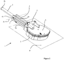
- a turret 100 of an armored vehicle (vehicle shown very schematically) comprises two manholes 101 and 102 intended to let in or out all or part of a crew member in a passenger compartment formed by the turret 100.
- Each manhole is closed by an articulated hatch 101a and 102a.
- One of the manholes 101 carries a light weapon system 1 according to the invention, which is intended to fire mortar shells.
- This weapon system 1 comprises a mortar tube 2 which is, according to the embodiment shown, oriented in parallel with the reference to the main weapon 100a of the turret 100.
- the bearing pointing of the weapon system 1 will therefore be carried out by rotating the turret or the entire vehicle.
- the weapon system 1 is fixed at the manhole by conventional fastening means, such as screws and / or bolts, other means may be used.
- the weapon system comprises a riser 3 which extends vertically above the manhole 101a (not visible hole).
- This enhancement 3 surrounds the entire periphery of the manhole.
- a support 4 of the mortar tube 2 is secured in a fixed manner at a first end of the riser 2, below a hinge 5 serving to open the hatch 6.
- the support 4 extending substantially horizontally in an interfacing plane P of the weapon system 1 on the manhole.
- the support 4 comprises at its second end a pivot connection 4b intended to allow the rotation of the tube 2 around the horizontal axis A to orient the tube 2 in place and thus adjust the rise.
- the support 4 comprises two lateral flanks 4a between which a front portion of the tube 2 having the mouth of the tube 2a can be placed when it is horizontal.
- the weapon system 1 comprises an orientation means 7 of the tube 2 in site.
- the orientation means 7 is an electric jack secured to a flank 4a of the support 4 and secured by another end of the pivot connection 4b connected to the tube 2 (for example by a connecting rod - crank system ).
- the second end of the jack may be integral with the tube 2 directly.
- This cylinder 7 is controllable from the cabin of the turret 100.
- the weapon system 1 comprises a measuring means (not shown) for the orientation of the tube 2.
- a measuring means for the orientation of the tube 2.
- Such means are well known to those skilled in the art, they may be constituted by an angular sensor for example or any other measuring means for indicating the value of pointing in site of the tube to a servant of the weapon system located in the cabin of the turret 100.
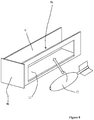
- the weapon system 1 is shown without its hatch or hinge to see the internal operation of the weapon system 1.
- the riser 3 has in its wall an opening 8 opening, towards the outside of the extension 3, between the flanks 4a of the support 4 and facing the mouth 2a of the tube 2 when it is at the horizontal.
- This opening 8 corresponds with a loading means 9 of the tube 2.
- This loading means may be a slide 9 which is slidably mounted by a sliding connection 10 in the opening 8, the sliding drawer of the inside of the riser 3 to outside and vice versa.
- the drawer 9 has on one of its sides a window 11 intended to allow to place a shell 12 inside the drawer 9.
- the shell 12 is placed so that its rear part is closest to the opening 8 so that this part subsequently enters the first in the mouth 2a of the tube 2 during the loading of the shell 12 as shown in FIG. figure 4 .
- the servant During loading, from the cabin of the turret 100, the servant has access to the drawer while being protected by the hatch 6 which closes the raiser (hatch not shown at the figure 4 ). It pushes the drawer towards the tube 2a, thus causing the shell 12 to enter the mouth of the tube 2a.
- the drawer 9 has a stretcher shape and therefore comprises a chute 9a which is dimensioned so as to allow the tube 2 to enter the drawer 9 when the latter is pushed to slide the shell 12 into the mouth 2a of the tube 2 .
- the chute 9a of the drawer 9 is also completely open in its upper part. Thus the tube can be rotated for its positioning in the site without being obstructed by the drawer 9.
- the slide 9 carries at its rear part a plate 9b ( figure 8 ) forming a closing means of the bottom of the opening 8.
- This plate 9b provides ballistic protection of the riser 3 after the tube tilted.
- a locking means (not shown) will lock the drawer 9 relative to the riser 3 in this position.
- the plate 9b will be made of a material having resistance capabilities similar to that of the riser 3 and will have a thickness of the same order as that of the riser.
- the drawer 9 is open on its upper part leaving the tube 2 apparent and free to move upwards.
- the servant controls the setting firing site from the inside of the turret by activating the cylinder 7.
- the tube 2 under the action of the orientation means 7, raises the mouth 2a of the tube which causes the descent of the shell at the bottom of the tube 2 by gravity.
- the servant can control the firing of the shell by means conventionally known to those skilled in the art such as a remotely controllable striker located in the cylinder head 2b of the tube 2.
- the weapon system According to a simpler embodiment of the weapon system according to the invention, it is conceivable not to equip the weapon system with a loading drawer. In this case, the shell will be inserted manually into the mouth of the tube through the opening 8.
- a pivoting flap may be provided to close the opening 8 but the ballistic seal is not guaranteed in this case during the loading phase.
- the small size of the opening 8 and its position protected by the flanks 4a of the support 4 provides a low exposure of the servant vis-à-vis the ballistic threats.
- the invention makes it possible to equip an armored vehicle with a light weapon system that can be safely served from the passenger compartment of the vehicle without causing the vehicle to be heavily modified.
- pivot connection 4b between the tube 2 and the support 4 is located cantilevered with respect to the turret nape. This allows the tube 2 to point in height without its breech interferes with the turret.
- the pivot connection 4b between the tube 2 and the support 4 is situated at the rear part of the tube, which avoids, during the raising of the tube 2, any interference with elements of the vehicle placed under the device 1.
Landscapes
- Engineering & Computer Science (AREA)
- General Engineering & Computer Science (AREA)
- Aiming, Guidance, Guns With A Light Source, Armor, Camouflage, And Targets (AREA)
Claims (8)
- - Leichtes Waffensystem (1) für Mörsergranaten (12), das mit einem Mannloch (101) eines Innenraums (100) verbunden ist und folgendes umfasst:- ein Mörserrohr (2)- eine Erhöhung (3), die das Mannloch (101) umgibt und senkrecht oberhalb des Mannlochs (101) verläuft, wobei die Erhöhung (3) von einer angelenkten Falltür (6) verschlossen wird und eine Öffnung (8) umfasst, damit das Mörserrohr (2) mit einer Granate (12) versorgt werden kann,- eine Stütze (4) des Mörserrohrs (2), die mit der Erhöhung (3) durch ein erstes Ende fest verbunden ist und an ihrem anderen Ende eine Drehzapfen-Verbindung (4a) umfasst, die mit dem Mörserrohr (2) verbunden ist,- wobei die Öffnung (8) nach außerhalb der Erhöhung (3) zwischen Flanken (4a) der Stütze (4) und gegenüber der Mündung (2a) des Rohrs (2) mündet, wenn diese waagrecht ist,- ein Ausrichtungsmittel (7) am Aufstellungsort des Mörserrohrs (2),- ein Zündmittel (2b), um den Schuss der Granate (12) auszulösen.
- - Leichtes Waffensystem (1) nach Anspruch 1, gekennzeichnet dadurch, dass es ein Verschlussmittel für die Öffnung (8) umfasst, das einen ballistischen Schutz garantiert.
- - Leichtes Waffensystem nach Anspruch 2, gekennzeichnet dadurch, dass das Verschlussmittel einstückig mit einem Belademittel mit einem Einschub (9) ist, der eine Granate (12) enthält, wobei der Einschub (9) durch eine Gleitverbindung (10) in der Öffnung (8) der Erhöhung (3) gleitend montiert ist.
- - Leichtes Waffensystem nach Anspruch 3, gekennzeichnet dadurch, dass der Einschub (9) eine Rinne (9a) umfasst, durch die das Rohr (2) hindurchgeht, wobei der Einschub durch sein Gleiten die Granate (12) in die Mündung (2a) des Rohrs (2) schiebt.
- - Leichtes Waffensystem (1) nach Anspruch 4, gekennzeichnet dadurch, dass die Rinne des Einschubs (9) oben offen ist, damit die Mündung (2a) des Rohrs (2) während der Positionierungsbewegungen vor Ort des Einschubs (9) in diesen ein- und wieder austreten kann.
- - Leichtes Waffensystem (1) nach einem der Ansprüche 1 bis 5, gekennzeichnet dadurch, dass es einen Ortswinkelsensor (20) umfasst, zum Anvisieren beim Heben des Rohrs (2).
- - Leichtes Waffensystem (1) nach einem der Ansprüche 1 bis 6, gekennzeichnet dadurch, dass das Zündmittel ein vom Fahrzeuginnern aus bedienbarer Schlagbolzen ist, der in dem Verschluss (2b) des Rohrs gelegen ist.
- - Leichtes Waffensystem nach einem der Ansprüche 1 bis 7, gekennzeichnet dadurch, dass das Mittel zur Ausrichtung (7) des Rohrs vor Ort ein elektrischer Stellzylinder (7) ist.
Priority Applications (1)
| Application Number | Priority Date | Filing Date | Title |
|---|---|---|---|
| PL14711805T PL2956738T3 (pl) | 2013-02-12 | 2014-02-07 | System broni lekkiej |
Applications Claiming Priority (2)
| Application Number | Priority Date | Filing Date | Title |
|---|---|---|---|
| FR1300314A FR3002030B1 (fr) | 2013-02-12 | 2013-02-12 | Systeme d'arme leger |
| PCT/FR2014/050240 WO2014125195A1 (fr) | 2013-02-12 | 2014-02-07 | Systeme d'arme leger |
Publications (2)
| Publication Number | Publication Date |
|---|---|
| EP2956738A1 EP2956738A1 (de) | 2015-12-23 |
| EP2956738B1 true EP2956738B1 (de) | 2017-04-19 |
Family
ID=48856677
Family Applications (1)
| Application Number | Title | Priority Date | Filing Date |
|---|---|---|---|
| EP14711805.3A Active EP2956738B1 (de) | 2013-02-12 | 2014-02-07 | Leichtes waffensystem |
Country Status (5)
| Country | Link |
|---|---|
| EP (1) | EP2956738B1 (de) |
| FR (1) | FR3002030B1 (de) |
| PL (1) | PL2956738T3 (de) |
| RU (1) | RU2638203C2 (de) |
| WO (1) | WO2014125195A1 (de) |
Citations (21)
| Publication number | Priority date | Publication date | Assignee | Title |
|---|---|---|---|---|
| FR819842A (fr) | 1936-06-29 | 1937-10-27 | Plate-forme orientable et pivotante pour armes à feu et autres applications analogues | |
| GB772463A (en) | 1954-02-16 | 1957-04-10 | Georges Even | Armoured vehicle |
| DE2043852A1 (de) | 1969-09-04 | 1971-03-11 | Societe Nationale Industrielle Aerospatiale Paris | Versenkbare Abschußvorrichtung fur Lenkwaffen |
| EP0011856A1 (de) | 1978-11-29 | 1980-06-11 | Industrie-Werke Karlsruhe Augsburg Aktiengesellschaft | Vorrichtung zum Verriegeln eines um eine liegende Drehachslinie drehbaren Trägers einer der Höhe nach richtbaren Waffe, z. B. einer Schnellfeuerkanone |
| DE3436369A1 (de) | 1984-10-04 | 1986-04-10 | Diehl GmbH & Co, 8500 Nürnberg | Waffensystem mit einer fahrzeuggebundenen vorderladerwaffe |
| EP0373283A1 (de) | 1987-12-14 | 1990-06-20 | NORICUM MASCHINENBAU UND HANDEL GESELLSCHAFT m.b.H. | Einrichtung zum Richten von mobilen Steilfeuerwaffen |
| EP0402753A2 (de) | 1989-06-12 | 1990-12-19 | DIEHL GMBH & CO. | Rohrwaffe |
| FR2674949A1 (fr) | 1991-04-04 | 1992-10-09 | Giat Ind Sa | Mortier par chargement a l'arriere. |
| EP0540848A1 (de) | 1991-11-07 | 1993-05-12 | Wegmann & Co. GmbH | Drehringlafette für eine leichte Waffe an einem Kampffahrzeug, insbesondere an einer Luke eines Kampfpanzers |
| DE3440467C2 (de) | 1984-11-06 | 1993-06-03 | Diehl Gmbh & Co, 8500 Nuernberg, De | |
| FR2698438A1 (fr) | 1992-11-26 | 1994-05-27 | Bofors Ab | Mortier. |
| DE4304761A1 (de) | 1993-02-17 | 1994-08-18 | Mak System Gmbh | Waffenlafette für Panzerfahrzeuge |
| EP1273869A2 (de) | 2001-07-07 | 2003-01-08 | Rheinmetall Landsysteme GmbH | Gepanzertes Fahrzeug |
| EP1318375A2 (de) | 2001-12-07 | 2003-06-11 | Rheinmetall Landsysteme GmbH | Luke für einen multifunktionalen Aufnahmering an gepanzerten Fahrzeugen |
| JP2003336998A (ja) | 2002-05-21 | 2003-11-28 | Komatsu Ltd | 車両搭載式火砲発射機構 |
| EP2124011A2 (de) | 2008-05-19 | 2009-11-25 | Alenia Aeronautica S.P.A. | Waffenturm, insbesondere für ein militärisches Panzerfahrzeuge, mit einer Waffenhalterung |
| DE102009009082A1 (de) | 2009-02-14 | 2010-08-19 | Krauss-Maffei Wegmann Gmbh & Co. Kg | Wirkmittelwurfsystem zum Abschuss nicht-letaler Wirkmittel von einem Fahrzeug, insbesondere einem Polizei-oder Militärfahrzeug |
| DE102007018507B4 (de) | 2007-04-19 | 2012-05-03 | Krauss-Maffei Wegmann Gmbh & Co. Kg | Verfahren und Vorrichtung zur Bekämpfung einer Angriffsmunitionskörper-Abschussvorrichtung |
| US20120167750A1 (en) | 2011-01-04 | 2012-07-05 | Lockheed Martin Corporation | Rapid fire launch system |
| DE102011050277B4 (de) | 2011-05-11 | 2012-11-29 | Krauss-Maffei Wegmann Gmbh & Co. Kg | Adapter zur Befestigung einer Lafette an einem Objekt, Lafette und militärisches Fahrzeug |
| DE102012001172A1 (de) | 2012-01-24 | 2013-07-25 | Rheinmetall Waffe Munition Gmbh | Waffe, wie Mörser oder Düsenmörser, mit Lafette |
Family Cites Families (2)
| Publication number | Priority date | Publication date | Assignee | Title |
|---|---|---|---|---|
| FR2163932A5 (de) * | 1971-12-07 | 1973-07-27 | France Etat | |
| RU2184333C2 (ru) * | 2000-08-21 | 2002-06-27 | Открытое акционерное общество "Завод им. В.А. Дегтярева" | Башня бронемашины с системой оружия |
-
2013
- 2013-02-12 FR FR1300314A patent/FR3002030B1/fr not_active Expired - Fee Related
-
2014
- 2014-02-07 PL PL14711805T patent/PL2956738T3/pl unknown
- 2014-02-07 WO PCT/FR2014/050240 patent/WO2014125195A1/fr active Application Filing
- 2014-02-07 EP EP14711805.3A patent/EP2956738B1/de active Active
- 2014-02-07 RU RU2015138764A patent/RU2638203C2/ru active
Patent Citations (21)
| Publication number | Priority date | Publication date | Assignee | Title |
|---|---|---|---|---|
| FR819842A (fr) | 1936-06-29 | 1937-10-27 | Plate-forme orientable et pivotante pour armes à feu et autres applications analogues | |
| GB772463A (en) | 1954-02-16 | 1957-04-10 | Georges Even | Armoured vehicle |
| DE2043852A1 (de) | 1969-09-04 | 1971-03-11 | Societe Nationale Industrielle Aerospatiale Paris | Versenkbare Abschußvorrichtung fur Lenkwaffen |
| EP0011856A1 (de) | 1978-11-29 | 1980-06-11 | Industrie-Werke Karlsruhe Augsburg Aktiengesellschaft | Vorrichtung zum Verriegeln eines um eine liegende Drehachslinie drehbaren Trägers einer der Höhe nach richtbaren Waffe, z. B. einer Schnellfeuerkanone |
| DE3436369A1 (de) | 1984-10-04 | 1986-04-10 | Diehl GmbH & Co, 8500 Nürnberg | Waffensystem mit einer fahrzeuggebundenen vorderladerwaffe |
| DE3440467C2 (de) | 1984-11-06 | 1993-06-03 | Diehl Gmbh & Co, 8500 Nuernberg, De | |
| EP0373283A1 (de) | 1987-12-14 | 1990-06-20 | NORICUM MASCHINENBAU UND HANDEL GESELLSCHAFT m.b.H. | Einrichtung zum Richten von mobilen Steilfeuerwaffen |
| EP0402753A2 (de) | 1989-06-12 | 1990-12-19 | DIEHL GMBH & CO. | Rohrwaffe |
| FR2674949A1 (fr) | 1991-04-04 | 1992-10-09 | Giat Ind Sa | Mortier par chargement a l'arriere. |
| EP0540848A1 (de) | 1991-11-07 | 1993-05-12 | Wegmann & Co. GmbH | Drehringlafette für eine leichte Waffe an einem Kampffahrzeug, insbesondere an einer Luke eines Kampfpanzers |
| FR2698438A1 (fr) | 1992-11-26 | 1994-05-27 | Bofors Ab | Mortier. |
| DE4304761A1 (de) | 1993-02-17 | 1994-08-18 | Mak System Gmbh | Waffenlafette für Panzerfahrzeuge |
| EP1273869A2 (de) | 2001-07-07 | 2003-01-08 | Rheinmetall Landsysteme GmbH | Gepanzertes Fahrzeug |
| EP1318375A2 (de) | 2001-12-07 | 2003-06-11 | Rheinmetall Landsysteme GmbH | Luke für einen multifunktionalen Aufnahmering an gepanzerten Fahrzeugen |
| JP2003336998A (ja) | 2002-05-21 | 2003-11-28 | Komatsu Ltd | 車両搭載式火砲発射機構 |
| DE102007018507B4 (de) | 2007-04-19 | 2012-05-03 | Krauss-Maffei Wegmann Gmbh & Co. Kg | Verfahren und Vorrichtung zur Bekämpfung einer Angriffsmunitionskörper-Abschussvorrichtung |
| EP2124011A2 (de) | 2008-05-19 | 2009-11-25 | Alenia Aeronautica S.P.A. | Waffenturm, insbesondere für ein militärisches Panzerfahrzeuge, mit einer Waffenhalterung |
| DE102009009082A1 (de) | 2009-02-14 | 2010-08-19 | Krauss-Maffei Wegmann Gmbh & Co. Kg | Wirkmittelwurfsystem zum Abschuss nicht-letaler Wirkmittel von einem Fahrzeug, insbesondere einem Polizei-oder Militärfahrzeug |
| US20120167750A1 (en) | 2011-01-04 | 2012-07-05 | Lockheed Martin Corporation | Rapid fire launch system |
| DE102011050277B4 (de) | 2011-05-11 | 2012-11-29 | Krauss-Maffei Wegmann Gmbh & Co. Kg | Adapter zur Befestigung einer Lafette an einem Objekt, Lafette und militärisches Fahrzeug |
| DE102012001172A1 (de) | 2012-01-24 | 2013-07-25 | Rheinmetall Waffe Munition Gmbh | Waffe, wie Mörser oder Düsenmörser, mit Lafette |
Also Published As
| Publication number | Publication date |
|---|---|
| RU2638203C2 (ru) | 2017-12-12 |
| EP2956738A1 (de) | 2015-12-23 |
| WO2014125195A1 (fr) | 2014-08-21 |
| PL2956738T3 (pl) | 2017-08-31 |
| FR3002030B1 (fr) | 2017-08-11 |
| FR3002030A1 (fr) | 2014-08-15 |
| RU2015138764A (ru) | 2017-03-17 |
Similar Documents
| Publication | Publication Date | Title |
|---|---|---|
| US8393258B2 (en) | Retractable turret | |
| US9080828B2 (en) | Assembly of turret and low radar reflection weapon | |
| EP1714105B1 (de) | Gesicherte vorrichtung zur zuführung und zündung von patronen wie zum beispiel scheinpatronen | |
| EP2672217A1 (de) | Motorisierte Drehscheibe für Revolverkopf-Zusatzelemente | |
| EP2071268B1 (de) | Versenkbare Luke | |
| EP1950522B1 (de) | Täuschkörperwerfer für Flugzeuge | |
| US9360266B2 (en) | Cannon and military vehicle | |
| EP2956738B1 (de) | Leichtes waffensystem | |
| EP2962060B1 (de) | Munition mit veränderbarer explosiver kapazität | |
| US20130213278A1 (en) | Gun port arrangement for an armoured structure | |
| FR2950962A1 (fr) | Tourelleau de montage d'un equipement, tel un armement secondaire | |
| EP2163843B1 (de) | Versenkbare Luke | |
| EP3699542B1 (de) | Tarnkappenfahrzeug mit integriertem waffensystem zur raschen bereitstellung | |
| FR3022338A1 (fr) | Tourelleau comportant un magasin a munitions | |
| EP2913628B1 (de) | Geschosszünder eines Artillerieprojektils, der eine in Flugrichtung wirkende Bremsvorrichtung umfasst | |
| IL229623A (en) | Entry pipe for firing sub-caliber ammunition bodies and weapons containing an entry pipe | |
| EP2437025B1 (de) | Waffensystem mit Rohrverlängerung | |
| WO2021070056A1 (fr) | Conteneur logistique destiné à être équipé d'au moins un moyen de protection | |
| FR3061768A1 (fr) | Dispositif d'evacuation de douilles | |
| FR2898968A1 (fr) | Amelioration de la protection des vehicules blindes | |
| EP3201557B1 (de) | Zugangsklappe für unbemannten turm eines gepanzerten fahrzeuges | |
| EP4339550A2 (de) | Drehturm mit versenkbarem schutzdach | |
| FR2725268A1 (fr) | Lanceur de projectile, a canon consommable | |
| FR3058789A1 (fr) | Systeme de tir de projectile |
Legal Events
| Date | Code | Title | Description |
|---|---|---|---|
| PUAI | Public reference made under article 153(3) epc to a published international application that has entered the european phase |
Free format text: ORIGINAL CODE: 0009012 |
|
| 17P | Request for examination filed |
Effective date: 20150911 |
|
| AK | Designated contracting states |
Kind code of ref document: A1 Designated state(s): AL AT BE BG CH CY CZ DE DK EE ES FI FR GB GR HR HU IE IS IT LI LT LU LV MC MK MT NL NO PL PT RO RS SE SI SK SM TR |
|
| AX | Request for extension of the european patent |
Extension state: BA ME |
|
| DAX | Request for extension of the european patent (deleted) | ||
| GRAP | Despatch of communication of intention to grant a patent |
Free format text: ORIGINAL CODE: EPIDOSNIGR1 |
|
| STAA | Information on the status of an ep patent application or granted ep patent |
Free format text: STATUS: GRANT OF PATENT IS INTENDED |
|
| INTG | Intention to grant announced |
Effective date: 20161129 |
|
| GRAS | Grant fee paid |
Free format text: ORIGINAL CODE: EPIDOSNIGR3 |
|
| GRAA | (expected) grant |
Free format text: ORIGINAL CODE: 0009210 |
|
| STAA | Information on the status of an ep patent application or granted ep patent |
Free format text: STATUS: THE PATENT HAS BEEN GRANTED |
|
| AK | Designated contracting states |
Kind code of ref document: B1 Designated state(s): AL AT BE BG CH CY CZ DE DK EE ES FI FR GB GR HR HU IE IS IT LI LT LU LV MC MK MT NL NO PL PT RO RS SE SI SK SM TR |
|
| REG | Reference to a national code |
Ref country code: GB Ref legal event code: FG4D Free format text: NOT ENGLISH |
|
| REG | Reference to a national code |
Ref country code: CH Ref legal event code: EP |
|
| REG | Reference to a national code |
Ref country code: AT Ref legal event code: REF Ref document number: 886397 Country of ref document: AT Kind code of ref document: T Effective date: 20170515 |
|
| REG | Reference to a national code |
Ref country code: IE Ref legal event code: FG4D Free format text: LANGUAGE OF EP DOCUMENT: FRENCH |
|
| REG | Reference to a national code |
Ref country code: DE Ref legal event code: R096 Ref document number: 602014008780 Country of ref document: DE |
|
| REG | Reference to a national code |
Ref country code: SE Ref legal event code: TRGR |
|
| REG | Reference to a national code |
Ref country code: NL Ref legal event code: MP Effective date: 20170419 |
|
| REG | Reference to a national code |
Ref country code: NO Ref legal event code: T2 Effective date: 20170419 |
|
| REG | Reference to a national code |
Ref country code: LT Ref legal event code: MG4D |
|
| REG | Reference to a national code |
Ref country code: AT Ref legal event code: MK05 Ref document number: 886397 Country of ref document: AT Kind code of ref document: T Effective date: 20170419 |
|
| PG25 | Lapsed in a contracting state [announced via postgrant information from national office to epo] |
Ref country code: NL Free format text: LAPSE BECAUSE OF FAILURE TO SUBMIT A TRANSLATION OF THE DESCRIPTION OR TO PAY THE FEE WITHIN THE PRESCRIBED TIME-LIMIT Effective date: 20170419 |
|
| PG25 | Lapsed in a contracting state [announced via postgrant information from national office to epo] |
Ref country code: ES Free format text: LAPSE BECAUSE OF FAILURE TO SUBMIT A TRANSLATION OF THE DESCRIPTION OR TO PAY THE FEE WITHIN THE PRESCRIBED TIME-LIMIT Effective date: 20170419 Ref country code: AT Free format text: LAPSE BECAUSE OF FAILURE TO SUBMIT A TRANSLATION OF THE DESCRIPTION OR TO PAY THE FEE WITHIN THE PRESCRIBED TIME-LIMIT Effective date: 20170419 Ref country code: GR Free format text: LAPSE BECAUSE OF FAILURE TO SUBMIT A TRANSLATION OF THE DESCRIPTION OR TO PAY THE FEE WITHIN THE PRESCRIBED TIME-LIMIT Effective date: 20170720 Ref country code: HR Free format text: LAPSE BECAUSE OF FAILURE TO SUBMIT A TRANSLATION OF THE DESCRIPTION OR TO PAY THE FEE WITHIN THE PRESCRIBED TIME-LIMIT Effective date: 20170419 Ref country code: LT Free format text: LAPSE BECAUSE OF FAILURE TO SUBMIT A TRANSLATION OF THE DESCRIPTION OR TO PAY THE FEE WITHIN THE PRESCRIBED TIME-LIMIT Effective date: 20170419 |
|
| PG25 | Lapsed in a contracting state [announced via postgrant information from national office to epo] |
Ref country code: BG Free format text: LAPSE BECAUSE OF FAILURE TO SUBMIT A TRANSLATION OF THE DESCRIPTION OR TO PAY THE FEE WITHIN THE PRESCRIBED TIME-LIMIT Effective date: 20170719 Ref country code: LV Free format text: LAPSE BECAUSE OF FAILURE TO SUBMIT A TRANSLATION OF THE DESCRIPTION OR TO PAY THE FEE WITHIN THE PRESCRIBED TIME-LIMIT Effective date: 20170419 Ref country code: IS Free format text: LAPSE BECAUSE OF FAILURE TO SUBMIT A TRANSLATION OF THE DESCRIPTION OR TO PAY THE FEE WITHIN THE PRESCRIBED TIME-LIMIT Effective date: 20170819 Ref country code: RS Free format text: LAPSE BECAUSE OF FAILURE TO SUBMIT A TRANSLATION OF THE DESCRIPTION OR TO PAY THE FEE WITHIN THE PRESCRIBED TIME-LIMIT Effective date: 20170419 |
|
| REG | Reference to a national code |
Ref country code: DE Ref legal event code: R026 Ref document number: 602014008780 Country of ref document: DE |
|
| REG | Reference to a national code |
Ref country code: FR Ref legal event code: PLFP Year of fee payment: 5 |
|
| PLBI | Opposition filed |
Free format text: ORIGINAL CODE: 0009260 |
|
| PG25 | Lapsed in a contracting state [announced via postgrant information from national office to epo] |
Ref country code: CZ Free format text: LAPSE BECAUSE OF FAILURE TO SUBMIT A TRANSLATION OF THE DESCRIPTION OR TO PAY THE FEE WITHIN THE PRESCRIBED TIME-LIMIT Effective date: 20170419 Ref country code: RO Free format text: LAPSE BECAUSE OF FAILURE TO SUBMIT A TRANSLATION OF THE DESCRIPTION OR TO PAY THE FEE WITHIN THE PRESCRIBED TIME-LIMIT Effective date: 20170419 Ref country code: DK Free format text: LAPSE BECAUSE OF FAILURE TO SUBMIT A TRANSLATION OF THE DESCRIPTION OR TO PAY THE FEE WITHIN THE PRESCRIBED TIME-LIMIT Effective date: 20170419 Ref country code: EE Free format text: LAPSE BECAUSE OF FAILURE TO SUBMIT A TRANSLATION OF THE DESCRIPTION OR TO PAY THE FEE WITHIN THE PRESCRIBED TIME-LIMIT Effective date: 20170419 Ref country code: SK Free format text: LAPSE BECAUSE OF FAILURE TO SUBMIT A TRANSLATION OF THE DESCRIPTION OR TO PAY THE FEE WITHIN THE PRESCRIBED TIME-LIMIT Effective date: 20170419 |
|
| PLAX | Notice of opposition and request to file observation + time limit sent |
Free format text: ORIGINAL CODE: EPIDOSNOBS2 |
|
| 26 | Opposition filed |
Opponent name: RHEINMETALL WAFFE MUNITION GMBH Effective date: 20180119 |
|
| PG25 | Lapsed in a contracting state [announced via postgrant information from national office to epo] |
Ref country code: SM Free format text: LAPSE BECAUSE OF FAILURE TO SUBMIT A TRANSLATION OF THE DESCRIPTION OR TO PAY THE FEE WITHIN THE PRESCRIBED TIME-LIMIT Effective date: 20170419 |
|
| PG25 | Lapsed in a contracting state [announced via postgrant information from national office to epo] |
Ref country code: SI Free format text: LAPSE BECAUSE OF FAILURE TO SUBMIT A TRANSLATION OF THE DESCRIPTION OR TO PAY THE FEE WITHIN THE PRESCRIBED TIME-LIMIT Effective date: 20170419 |
|
| PLBB | Reply of patent proprietor to notice(s) of opposition received |
Free format text: ORIGINAL CODE: EPIDOSNOBS3 |
|
| REG | Reference to a national code |
Ref country code: CH Ref legal event code: PL |
|
| PG25 | Lapsed in a contracting state [announced via postgrant information from national office to epo] |
Ref country code: MC Free format text: LAPSE BECAUSE OF FAILURE TO SUBMIT A TRANSLATION OF THE DESCRIPTION OR TO PAY THE FEE WITHIN THE PRESCRIBED TIME-LIMIT Effective date: 20170419 Ref country code: MT Free format text: LAPSE BECAUSE OF FAILURE TO SUBMIT A TRANSLATION OF THE DESCRIPTION OR TO PAY THE FEE WITHIN THE PRESCRIBED TIME-LIMIT Effective date: 20170419 |
|
| REG | Reference to a national code |
Ref country code: IE Ref legal event code: MM4A |
|
| REG | Reference to a national code |
Ref country code: BE Ref legal event code: MM Effective date: 20180228 |
|
| PG25 | Lapsed in a contracting state [announced via postgrant information from national office to epo] |
Ref country code: CH Free format text: LAPSE BECAUSE OF NON-PAYMENT OF DUE FEES Effective date: 20180228 Ref country code: LU Free format text: LAPSE BECAUSE OF NON-PAYMENT OF DUE FEES Effective date: 20180207 Ref country code: LI Free format text: LAPSE BECAUSE OF NON-PAYMENT OF DUE FEES Effective date: 20180228 |
|
| PG25 | Lapsed in a contracting state [announced via postgrant information from national office to epo] |
Ref country code: IE Free format text: LAPSE BECAUSE OF NON-PAYMENT OF DUE FEES Effective date: 20180207 |
|
| PG25 | Lapsed in a contracting state [announced via postgrant information from national office to epo] |
Ref country code: BE Free format text: LAPSE BECAUSE OF NON-PAYMENT OF DUE FEES Effective date: 20180228 |
|
| REG | Reference to a national code |
Ref country code: DE Ref legal event code: R100 Ref document number: 602014008780 Country of ref document: DE |
|
| PLCK | Communication despatched that opposition was rejected |
Free format text: ORIGINAL CODE: EPIDOSNREJ1 |
|
| PLBN | Opposition rejected |
Free format text: ORIGINAL CODE: 0009273 |
|
| STAA | Information on the status of an ep patent application or granted ep patent |
Free format text: STATUS: OPPOSITION REJECTED |
|
| 27O | Opposition rejected |
Effective date: 20190626 |
|
| PG25 | Lapsed in a contracting state [announced via postgrant information from national office to epo] |
Ref country code: PT Free format text: LAPSE BECAUSE OF FAILURE TO SUBMIT A TRANSLATION OF THE DESCRIPTION OR TO PAY THE FEE WITHIN THE PRESCRIBED TIME-LIMIT Effective date: 20170419 |
|
| PG25 | Lapsed in a contracting state [announced via postgrant information from national office to epo] |
Ref country code: HU Free format text: LAPSE BECAUSE OF FAILURE TO SUBMIT A TRANSLATION OF THE DESCRIPTION OR TO PAY THE FEE WITHIN THE PRESCRIBED TIME-LIMIT; INVALID AB INITIO Effective date: 20140207 Ref country code: MK Free format text: LAPSE BECAUSE OF NON-PAYMENT OF DUE FEES Effective date: 20170419 Ref country code: CY Free format text: LAPSE BECAUSE OF FAILURE TO SUBMIT A TRANSLATION OF THE DESCRIPTION OR TO PAY THE FEE WITHIN THE PRESCRIBED TIME-LIMIT Effective date: 20170419 |
|
| PG25 | Lapsed in a contracting state [announced via postgrant information from national office to epo] |
Ref country code: AL Free format text: LAPSE BECAUSE OF FAILURE TO SUBMIT A TRANSLATION OF THE DESCRIPTION OR TO PAY THE FEE WITHIN THE PRESCRIBED TIME-LIMIT Effective date: 20170419 |
|
| PGFP | Annual fee paid to national office [announced via postgrant information from national office to epo] |
Ref country code: NO Payment date: 20230120 Year of fee payment: 10 Ref country code: FR Payment date: 20230119 Year of fee payment: 10 |
|
| PGFP | Annual fee paid to national office [announced via postgrant information from national office to epo] |
Ref country code: TR Payment date: 20230125 Year of fee payment: 10 Ref country code: SE Payment date: 20230119 Year of fee payment: 10 Ref country code: PL Payment date: 20230123 Year of fee payment: 10 Ref country code: IT Payment date: 20230120 Year of fee payment: 10 |
|
| PGFP | Annual fee paid to national office [announced via postgrant information from national office to epo] |
Ref country code: FI Payment date: 20240123 Year of fee payment: 11 Ref country code: DE Payment date: 20240123 Year of fee payment: 11 Ref country code: GB Payment date: 20240123 Year of fee payment: 11 |