EP2956349B1 - Dispositif d'escamotage d'une colonne de direction - Google Patents
Dispositif d'escamotage d'une colonne de direction Download PDFInfo
- Publication number
- EP2956349B1 EP2956349B1 EP13820836.8A EP13820836A EP2956349B1 EP 2956349 B1 EP2956349 B1 EP 2956349B1 EP 13820836 A EP13820836 A EP 13820836A EP 2956349 B1 EP2956349 B1 EP 2956349B1
- Authority
- EP
- European Patent Office
- Prior art keywords
- steering column
- geared motor
- outer tube
- leg
- motor unit
- Prior art date
- Legal status (The legal status is an assumption and is not a legal conclusion. Google has not performed a legal analysis and makes no representation as to the accuracy of the status listed.)
- Active
Links
Images




Classifications
-
- B—PERFORMING OPERATIONS; TRANSPORTING
- B62—LAND VEHICLES FOR TRAVELLING OTHERWISE THAN ON RAILS
- B62D—MOTOR VEHICLES; TRAILERS
- B62D1/00—Steering controls, i.e. means for initiating a change of direction of the vehicle
- B62D1/02—Steering controls, i.e. means for initiating a change of direction of the vehicle vehicle-mounted
- B62D1/16—Steering columns
- B62D1/18—Steering columns yieldable or adjustable, e.g. tiltable
- B62D1/181—Steering columns yieldable or adjustable, e.g. tiltable with power actuated adjustment, e.g. with position memory
Definitions
- the present invention relates to a steering column of a motor vehicle.
- a driver rides in a car he may be embarrassed to sit because of the steering wheel that is placed in front of the seat. It is possible to hide the steering wheel and leave room for the driver to sit down.
- the steering column which adjusts the position of the steering wheel to improve the ergonomics of the driving position, also in some cases to put the steering wheel in a specific position that facilitates the exit or installation of the driver in the vehicle: it is the function of retraction.
- the existing devices use an axial steering function of the steering wheel, which can sometimes be combined with a function of vertical adjustment of the steering wheel.
- Each function uses a specific engine.
- the axial adjustment of the steering wheel is performed at a relatively slow speed to allow precise positioning of the steering wheel when the driver adjusts the depth of the steering wheel.
- the speed of retraction is identical to that of the adjustment of the steering wheel which generates a significant execution time of the retraction function, especially if the stroke thereof is greater than that concerning the adjustment of the position of the wheel.
- the document EP1733950 A1 describes the preamble of claim 1.
- the object of the present invention is to provide a steering column that allows a larger and faster retraction of the steering wheel.
- the steering column comprises a lug, a cap, an inner tube, an outer tube, a steering wheel tip and at least one adjusting gear motor, it is characterized in that the leg is movable axially and that the column comprises a gear motor controlling the leg.
- the fact of having a movable lug makes it possible to increase the retraction length of the steering wheel, indeed, the deflection is the sum of the movements of the lug and the gear motor of adjustment whereas in the state of the art only the outer tube is movable in translation or vertically.
- Geared motors may be electric.
- the outer tube is axially movable and an axial adjustment gear motor controls said outer tube.
- the movement of the steering wheel is then the sum of the translation of the tab and the outer tube.
- the column is tilting and a vertical adjustment gear motor controls the inclination of said column.
- the deflection of the steering wheel is then the sum of the translation of the leg and the outer tube and the inclination of the steering column.
- a control device actuates geared motors.
- the geared motors are operated by the same control device.
- the controller can be set to turn on the retract feature when the driver turns off the vehicle and reposition the steering wheel when it turns the ignition on.
- control device actuates all the geared motors at the same time.
- the resulting speed is increased for executing the steering wheel retraction function.
- the outer tube slides on the inner tube.
- the two outer and inner tubes are coaxial and allow to adjust the depth of the steering wheel.
- the sliding of the outer tube on the inner tube takes place with a sheath. This makes it possible to limit the friction forces and the noise during the axial adjustment of the steering wheel. This also allows a connection without play between the tubes to have a good stiffness.
- the tab slides inside the cap by means of a guide system composed of rails and balls.
- the tab slides inside the cap by friction. This solution is cheaper.
- the axial adjustment geared motor is connected to the outer tube by a threaded axis.
- the threaded shaft allows fine adjustment of the steering wheel by the driver.
- the axial adjustment geared motor is fixed on the lug.
- the axial adjustment geared motor is fixed on the outer tube.
- the retracting geared motor is fixed on the cap.
- the retraction geared motor is fixed on the tab.
- the tab slides in the cap with a vertical angle relative to the displacement of the outer tube. This makes it possible to have the vertical ascent of the steering wheel at the same time as the axial displacement and makes it possible to clear more space for access to the vehicle.
- the tab slides in the cap parallel to the displacement of the outer tube.
- the system is more compact.
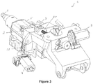
- the steering column 1 illustrated in figures 1 , 2 and 3 comprises a cap 2, a lug 3, an inner tube 4, an outer tube 5, a flying ferrule 6, an axial adjustment geared motor 7, a vertical adjustment geared motor 8 and a geared motor 9.
- the flying ferrule 6 is linked to the outer tube 5.
- the axial adjustment geared motor 7 is fixed on the lug 3.
- a screw 50 is connected to the geared motor 7 and fixed to the outer tube 5. The action of the geared motor 7 slides the outer tube 5 back and forth.
- the vertical adjustment geared motor 8, illustrated figures 2 and 3 is fixed on the lug 3 and actuates a screw 32 which cooperates with a square nut 33 and makes it possible to orient the outer tube 5 vertically (cf. figure 9 ).
- the geared motor 9 is fixed on the cap 2.
- a screw 20 is connected to the motor 9, fixed on the leg 3 and allows the retraction of the steering wheel.
- the position of the steering wheel (not shown), fixed on the flying endpiece 6, is adjustable via the geared motors 7 and 9.
- the upper tube 5 slides on the inner tube 4 with a intermediate sleeve 40 and the column is oriented vertically by a rotational movement about an axis X substantially horizontal with respect to the vehicle and perpendicular to the main axis of the column 1.
- the sliding between tube 4 and tube 5 can also s' without sheath, with or without surface coating.
- the activation of the geared motor 7 makes it possible to adjust the position of the flywheel in the axis of the tubes 4 and 5.
- the supply voltage of the geared motor 7 makes it possible to control the speed of this adjustment of the outer tube 5 on the inner tube 4 : either V1, axial direction or substantially horizontal.
- the geared motor 8 makes it possible to orient the position of the steering wheel at the top or at the bottom.
- the supply voltage of the geared motor 8 makes it possible to adjust the speed of the inclination of the steering wheel: that is to say V2, of vertical direction.
- the activation of the geared motor 9 allows the leg 3 to slide in the cap 2 which at the same time drives the motor 7, the screw 50, the outer tube 5 and the flying end 6 to adjust the position of the steering wheel.
- the supply voltage of the geared motor 9 makes it possible to control the speed of this adjustment: V3. This velocity has a vertical component V3v and a horizontal or axial component V3h.
- the outer tube 5 slides on the inner tube 4 and the lug 3 slides inside the cap 2 by means of a guide system composed of rails 30 and balls 31 ( figure 8 ).
- a guide system composed of rails 30 and balls 31 ( figure 8 ).
- the ball system may be replaced by a friction system with or without a surface coating without departing from the scope of the present invention.
- Column 1 is then in the retracted position as illustrated in FIGS. figures 4 and 7 .
- the tilt adjustment gearmotor 8 can be combined with the others to raise the steering wheel and thus better clear access to the driver's seat.
Landscapes
- Engineering & Computer Science (AREA)
- Chemical & Material Sciences (AREA)
- Combustion & Propulsion (AREA)
- Transportation (AREA)
- Mechanical Engineering (AREA)
- Steering Controls (AREA)
- Body Structure For Vehicles (AREA)
Description
- La présente invention se rapporte à une colonne de direction d'un véhicule automobile. En particulier, lorsqu'un conducteur monte dans une voiture il peut être gêné pour s'assoir à cause du volant qui est placé devant le siège. Il est possible d'escamoter le volant et de laisser de la place au conducteur pour s'assoir.
- La colonne de direction qui permet d'ajuster la position du volant afin d'améliorer l'ergonomie du poste de conduite, permet également dans certain cas de mettre le volant dans une position spécifique qui facilite la sortie ou l'installation du conducteur dans le véhicule : c'est la fonction d'escamotage. Plus la course d'escamotage est importante et plus elle sera intéressante pour l'utilisateur, et faciliter son installation dans son siège.
- Pour effectuer cette fonction d'escamotage, les dispositifs existant utilisent une fonction d'ajustement axial du volant, qui peut parfois être combinée avec une fonction d'ajustement vertical du volant. Chaque fonction utilise un moteur spécifique.
- Cependant, l'ajustement axial du volant est effectué à une vitesse relativement lente pour permettre un positionnement précis du volant lorsque le conducteur règle la profondeur du volant. La vitesse d'escamotage est identique à celle de l'ajustement du volant ce qui engendre un temps d'exécution important de la fonction escamotage, surtout si la course de celle-ci est plus importante que celle concernant l'ajustement de la position du volant. Le document
EP1733950 A1 décrit le préambule de la revendication 1. - L'objet de la présente invention est de proposer une colonne de direction qui permette un escamotage plus important et plus rapide du volant.
- La colonne de direction selon l'invention comprend une patte, une casquette, un tube intérieur, un tube extérieur, un embout de volant et au moins un motoréducteur d'ajustement, elle est caractérisée en ce que la patte est mobile axialement et que la colonne comprend un motoréducteur commandant la patte. Le fait d'avoir une patte mobile permet d'augmenter la longueur d'escamotage du volant, en effet, le débattement est la somme des mouvements de la patte et du motoréducteur d'ajustement alors que dans l'état de la technique seul le tube extérieur est mobile en translation ou verticalement. Les motoréducteurs pourront être électriques.
- Selon l'invention le tube extérieur est mobile axialement et un motoréducteur d'ajustement axial commande ledit tube extérieur. Le débattement du volant est alors la somme de la translation de la patte et du tube extérieur.
- Selon une autre caractéristique, la colonne est inclinable et qu'un motoréducteur d'ajustement vertical commande l'inclinaison de ladite colonne. Le débattement du volant est alors la somme de la translation de la patte et du tube extérieur et l'inclinaison de la colonne de direction.
- Selon une disposition particulière, un dispositif de commande actionne les motoréducteurs. Les motoréducteurs sont actionnés par un même dispositif de commande. Le dispositif de commande peut être réglé afin de mettre en marche la fonction d'escamotage lorsque le conducteur coupe le contact du véhicule et de repositionner le volant quand il remet le contact.
- Selon une autre disposition, le dispositif de commande actionne tous les motoréducteurs en même temps. En actionnant simultanément le moteur d'ajustement axial du volant, le moteur d'ajustement vertical de la colonne et le moteur d'escamotage, on augmente la vitesse résultante pour l'exécution de la fonction escamotage du volant.
- Selon une caractéristique particulière, le tube extérieur coulisse sur le tube intérieur. Les deux tubes extérieur et intérieur sont coaxiaux et permettent de régler la profondeur du volant.
- Selon une autre caractéristique particulière, le coulissement du tube extérieur sur le tube intérieur s'effectue avec un fourreau. Cela permet de limiter les efforts de friction et le bruit lors de l'ajustement axial du volant. Cela permet également une connexion sans jeu entre les tubes pour avoir une bonne raideur.
- Selon une mode de réalisation particulier, la patte coulisse à l'intérieur de la casquette par l'intermédiaire d'un système de guidage composé de rails et de billes. On a ainsi les mêmes avantages qu'avec le foureau pour l'escamotage du volant et cela évite aussi le jeu entre les pièces pour avoir une raideur élevée. Il n'y a pas d'influence par rapport aux efforts latéraux.
- Selon une autre mode de réalisation, la patte coulisse à l'intérieur de la casquette par friction. Cette solution est moins chère.
- Selon une disposition particulière, le motoréducteur d'ajustement axial est relié au tube extérieur par un axe fileté. L'axe fileté permet un réglage fin du volant par le conducteur.
- Selon une première disposition, le motoréducteur d'ajustement axial est fixé sur la patte.
- Selon une deuxième disposition, le motoréducteur d'ajustement axial est fixé sur le tube extérieur.
- Selon un deuxième mode de réalisation, le motoréducteur d'escamotage est fixé sur la casquette.
- Selon un premier mode de réalisation, le motoréducteur d'escamotage est fixé sur la patte.
- Selon un premier dispositif, la patte coulisse dans la casquette avec un angle vertical par rapport au déplacement du tube extérieur. Ceci permet d'avoir la remontée verticale du volant en même temps que le déplacement axial et permet de dégager plus de place pour accède rua véhicule.
- Selon un deuxième dispositif, la patte coulisse dans la casquette parallèlement au déplacement du tube extérieur. Le système est plus compact.
- D'autres avantages pourront encore apparaître à l'homme du métier à la lecture des exemples ci-dessous, illustrés par les figures annexées, donnés à titre d'exemple.
- La
figure 1 est une vue en perspective d'une colonne de direction selon l'invention, - La
figure 2 représente une vue en perspective de l'autre coté par rapport à lafigure 1 , - La
figure 3 est une vue en perspective d'une colonne de direction vue de l'arrière, - La
figure 4 est une vue en perspective d'une colonne de direction selon l'invention en position escamotée, - Les
figures 5, 6 et 7 sont des vues de coté d'une colonne de direction en position déployée, en position reculée et en position escamotée, - La
figure 8 est une vue en coupe en bout de casquette, - La
figure 9 est une vue en coupe à la hauteur d'un motoréducteur d'escamotage vertical, - La
figure 10 est une vue éclatée de la colonne de direction. - La colonne de direction 1 illustrée aux
figures 1 ,2 et3 comprend une casquette 2, une patte 3, un tube intérieur 4, un tube extérieur 5, un embout volant 6, un motoréducteur d'ajustement axial 7, un motoréducteur d'ajustement vertical 8 et un motoréducteur 9. L'embout volant 6 est lié au tube extérieur 5. - Sur la
figure 1 , le motoréducteur d'ajustement axial 7 est fixé sur la patte 3. Une vis 50 est connectée au motoréducteur 7 et fixée sur le tube extérieur 5. L'action du motoréducteur 7 fait coulisser le tube externe 5 d'avant en arrière. - Le motoréducteur d'ajustement vertical 8, illustré
figures 2 et3 , est fixé sur la patte 3 et actionne une vis 32 qui coopère avec un écrou carré 33 et permet d'orienter verticalement le tube extérieur 5 (cffigure 9 ). - Sur la
figure 1 , le motoréducteur 9 est fixé sur la casquette 2. Une vis 20 est connectée au moteur 9, fixée sur la patte 3 et permet l'escamotage du volant. - La position du volant (non représenté), fixé sur l'embout volant 6, est ajustable par l'intermédiaire des motoréducteurs 7 et 9. Lors de l'ajustement ergonomique du volant, le tube supérieur 5 coulisse sur le tube intérieur 4 avec un fourreau intermédiaire 40 et la colonne est orientée verticalement par un mouvement de rotation autour d'un axe X sensiblement horizontal par rapport au véhicule et perpendiculaire à l'axe principal de la colonne 1. Le coulissement entre tube 4 et tube 5 peut aussi s'effectuer sans fourreau, avec ou sans revêtement de surface.
- La mise en fonction du motoréducteur 7 permet d'ajuster la position du volant dans l'axe des tubes 4 et 5. La tension d'alimentation du motoréducteur 7 permet de maitriser la vitesse de cet ajustement du tube extérieur 5 sur le tube intérieur 4: soit V1, de direction axiale ou sensiblement horizontale.
- La mise en fonction du motoréducteur 8 permet d'orienter la position du volant en haut ou en bas. La tension d'alimentation du motoréducteur 8 permet de régler la vitesse de l'inclinaison du volant : soit V2, de direction verticale.
- La mise en fonction du motoréducteur 9 permet de faire coulisser la patte 3 dans la casquette 2 qui entraine en même temps le moteur 7, la vis 50, le tube extérieur 5 et l'embout volant 6 afin d'ajuster la position du volant. La tension d'alimentation du motoréducteur 9 permet de maitriser la vitesse de cet ajustement : V3. Cette vitesse a une composante verticale V3v et une composante horizontale ou axiale V3h.
- La mise en fonction simultanée des motoréducteurs 7, 8 et 9 permet d'ajuster la position du volant. La vitesse de ce mouvement est alors une combinaison des 3 vitesses individuelles, soit V4 avec une composante horizontale V4h= V1 + V3h et une composante verticale V4v = V2 + V3v.
- Il est possible de prévoir que seulement un motoréducteur d'ajustement soit actionné 7 ou 8 (et non les deux 7 et 8) avec le motoréducteur 9, on aura alors V'4 avec deux composantes :
V'4h= V3h et V'4v= V2 + V3v
ou V"4 avec deux composantes :
V"4h= V1 + V3h et V"4v= V3v. - Nous allons maintenant décrire l'escamotage du volant. Le tube extérieur 5 coulisse sur le tube intérieur 4 et la patte 3 coulisse à l'intérieur de la casquette 2 par l'intermédiaire d'un système de guidage composé de rails 30 et de billes 31 (
figure 8 ). On pourra par exemple avoir deux rangées de 3 billes 31 et quatre rails 30. Le système à bille peut être remplacé par un système à friction avec ou sans revêtement de surface sans sortir du cadre de la présente invention. La colonne 1 est alors en position escamotée comme illustré auxfigures 4 et7 . - Le motoréducteur d'ajustement d'inclinaison 8 peut être combiné avec les autres pour relever le volant et ainsi mieux dégager encore l'accès au siège conducteur.
- Sans sortir du cadre de la présente invention, il est possible de modifier certaines caractéristiques comme par exemple :
- intégrer un système d'absorption d'énergie entre la casquette 2 et la patte 3,
- avoir une direction de déplacement de la patte 3 dans la casquette 2 parallèle aux axes des tubes 4 et 5 ou bien suivant une direction spécifique
- prévoir que le motoréducteur d'ajustement vertical 8 pour le réglage vertical est fixé sur la casquette 2 au lieu de la patte 3,
- fixer le motoréducteur 9 sur la patte 3 au lieu de la casquette 2,
- fixer le motoréducteur d'ajustement axial 7 sur le sur tube extérieur 5 au lieu de la patte 3,
- avoir un guidage entre la patte 3 et la caquette 2 qui peut être rectiligne, curviligne ou autre profil spécifique
Claims (15)
- Colonne de direction (1) comprenant une patte (3), une casquette (2), un tube intérieur (4), un tube extérieur (5), un embout de volant (6) et au moins un motoréducteur d'ajustement (7, 8), la patte (3) étant mobile axialement et la colonne (1) comprenant un motoréducteur (9) commandant la patte (3) caractérisée en ce que le tube extérieur (5) est mobile axialement et qu'un motoréducteur d'ajustement axial (7) commande ledit tube extérieur (5).
- Colonne de direction (1) selon une des revendications précédentes, caractérisé en ce que la colonne (1) est inclinable et qu'un motoréducteur d'ajustement vertical (8) commande l'inclinaison de ladite colonne (1).
- Colonne de direction (1) selon une des revendications précédentes, caractérisé en ce qu'un dispositif de commande actionne les motoréducteurs (7, 8, 9).
- Colonne de direction (1) selon la revendication précédente, caractérisé en ce que le dispositif de commande actionne tous les motoréducteurs (7, 8, 9) en même temps.
- Colonne de direction (1) selon une des revendications précédentes, caractérisé en ce que le tube extérieur (5) coulisse sur le tube intérieur (4).
- Colonne de direction (1) selon la revendication précédente, caractérisé en ce que le coulissement du tube extérieur (5) sur le tube intérieur (4) s'effectue avec un fourreau (40).
- Colonne de direction (1) selon une des revendications précédentes, caractérisé en ce que la patte (3) coulisse à l'intérieur de la casquette (2) par l'intermédiaire d'un système de guidage composé de rails (30) et de billes (31).
- Colonne de direction (1) selon la revendication précédente, caractérisé en ce que la patte (3) coulisse à l'intérieur de la casquette (2) par friction.
- Colonne de direction (1) selon une des revendications précédentes, caractérisé en ce que le motoréducteur d'ajustement axial (7) est relié au tube extérieur (5) par une vis filetée (50).
- Colonne de direction (1) selon une des revendications précédentes, caractérisé en ce que le motoréducteur d'ajustement axial (7) est fixé sur la patte (3).
- Colonne de direction (1) selon une des revendications 1 à 10, caractérisé en ce que le motoréducteur d'ajustement axial est fixé sur le tube extérieur.
- Colonne de direction (1) selon une des revendications précédentes, caractérisé en ce que le motoréducteur (9) est fixé sur la casquette (2).
- Colonne de direction (1) selon une des revendications 1 à 11, caractérisé en ce que le motoréducteur (9) est fixé sur la patte (3).
- Colonne de direction (1) selon une des revendications précédentes, caractérisé en ce que la patte coulisse dans la casquette avec un angle vertical par rapport au déplacement du tube extérieur.
- Colonne de direction (1) selon une des revendications précédentes, caractérisé en ce que la patte coulisse dans la casquette parallèlement au déplacement du tube extérieur.
Applications Claiming Priority (3)
| Application Number | Priority Date | Filing Date | Title |
|---|---|---|---|
| FR1351197A FR3001940A1 (fr) | 2013-02-12 | 2013-02-12 | Dispositif d'escamotage d'une colonne de direction. |
| FR1351340A FR3001941B1 (fr) | 2013-02-12 | 2013-02-15 | Dispositif d'escamotage d'une colonne de direction. |
| PCT/FR2013/053205 WO2014125174A1 (fr) | 2013-02-12 | 2013-12-19 | Dispositif d'escamotage d'une colonne de direction |
Publications (2)
| Publication Number | Publication Date |
|---|---|
| EP2956349A1 EP2956349A1 (fr) | 2015-12-23 |
| EP2956349B1 true EP2956349B1 (fr) | 2018-12-12 |
Family
ID=48083430
Family Applications (1)
| Application Number | Title | Priority Date | Filing Date |
|---|---|---|---|
| EP13820836.8A Active EP2956349B1 (fr) | 2013-02-12 | 2013-12-19 | Dispositif d'escamotage d'une colonne de direction |
Country Status (5)
| Country | Link |
|---|---|
| US (1) | US9487228B2 (fr) |
| EP (1) | EP2956349B1 (fr) |
| CN (1) | CN105102300B (fr) |
| FR (2) | FR3001940A1 (fr) |
| WO (1) | WO2014125174A1 (fr) |
Cited By (2)
| Publication number | Priority date | Publication date | Assignee | Title |
|---|---|---|---|---|
| WO2020260353A1 (fr) * | 2019-06-25 | 2020-12-30 | Brose Fahrzeugteile SE & Co. Kommanditgesellschaft, Coburg | Dispositif de direction réglable par moteur électrique d'un véhicule à moteur terrestre |
| DE102021214797A1 (de) | 2021-12-21 | 2023-06-22 | Thyssenkrupp Ag | Lenksystem für ein Kraftfahrzeug |
Families Citing this family (34)
| Publication number | Priority date | Publication date | Assignee | Title |
|---|---|---|---|---|
| FR2979403B1 (fr) | 2011-08-31 | 2014-02-14 | Zf Systemes De Direction Nacam Sas | Dispositif de liaison d'une colonne de direction avec un boitier de direction. |
| FR3027862B1 (fr) | 2014-10-30 | 2016-11-25 | Zf Systemes De Direction Nacam Sas | Colonne de direction de vehicule comprenant une cale a cremaillere |
| US11560169B2 (en) | 2015-06-11 | 2023-01-24 | Steering Solutions Ip Holding Corporation | Retractable steering column system and method |
| US10343706B2 (en) | 2015-06-11 | 2019-07-09 | Steering Solutions Ip Holding Corporation | Retractable steering column system, vehicle having the same, and method |
| CN106256651B (zh) | 2015-06-16 | 2019-06-04 | 操纵技术Ip控股公司 | 可缩回转向柱组件及方法 |
| DE102016111473A1 (de) | 2015-06-25 | 2016-12-29 | Steering Solutions Ip Holding Corporation | Stationäre lenkradbaugruppe und verfahren |
| DE102016202465B4 (de) | 2016-02-18 | 2019-05-29 | Thyssenkrupp Ag | Motorisch verstellbare Lenksäule für ein Kraftfahrzeug |
| CN107521547B (zh) | 2016-06-21 | 2020-03-10 | 操纵技术Ip控股公司 | 转向柱组件的自锁伸缩式致动器 |
| US10457313B2 (en) | 2016-06-28 | 2019-10-29 | Steering Solutions Ip Holding Corporation | ADAS wheel locking device |
| US10363958B2 (en) | 2016-07-26 | 2019-07-30 | Steering Solutions Ip Holding Corporation | Electric power steering mode determination and transitioning |
| US10189496B2 (en) | 2016-08-22 | 2019-01-29 | Steering Solutions Ip Holding Corporation | Steering assembly having a telescope drive lock assembly |
| US20180086378A1 (en) * | 2016-09-27 | 2018-03-29 | Steering Solutions Ip Holding Corporation | Position detection system for a retractable steering column |
| CN110139792B (zh) * | 2016-11-17 | 2022-03-22 | 罗伯特·博世汽车转向有限责任公司 | 用于可调节转向柱的运动控制装置 |
| US10351160B2 (en) | 2016-11-30 | 2019-07-16 | Steering Solutions Ip Holding Corporation | Steering column assembly having a sensor assembly |
| US10370022B2 (en) | 2017-02-13 | 2019-08-06 | Steering Solutions Ip Holding Corporation | Steering column assembly for autonomous vehicle |
| US10385930B2 (en) | 2017-02-21 | 2019-08-20 | Steering Solutions Ip Holding Corporation | Ball coupling assembly for steering column assembly |
| CN109664932B (zh) * | 2017-10-17 | 2021-12-31 | 操纵技术Ip控股公司 | 可收起的转向柱设备 |
| US10577010B2 (en) * | 2018-01-08 | 2020-03-03 | Steering Solutions Ip Holding Corporation | Telescoping steering column |
| US10640139B2 (en) * | 2018-01-08 | 2020-05-05 | Steering Solutions Ip Holding Corporation | Telescoping steering column |
| US10974756B2 (en) | 2018-07-31 | 2021-04-13 | Steering Solutions Ip Holding Corporation | Clutch device latching system and method |
| KR102111357B1 (ko) * | 2018-09-21 | 2020-05-15 | 주식회사 만도 | 차량의 조향 컬럼 |
| DE102018127098B3 (de) * | 2018-10-30 | 2019-11-21 | Thyssenkrupp Ag | Lenkwelle für eine Lenksäule eines Kraftfahrzeugs und Lenksäule für ein Kraftfahrzeug |
| US11472465B2 (en) * | 2019-04-25 | 2022-10-18 | Jtekt Corporation | Steering device |
| US11383756B2 (en) * | 2019-11-06 | 2022-07-12 | Steering Solutions Ip Holding Corporation | System, method and apparatus translating and telescoping a steering column |
| CN114650943B (zh) * | 2019-11-22 | 2024-10-08 | 罗伯特博世汽车转向旺多姆公司 | 包括用于调节两个管之间的相对位置的调节系统的转向柱套筒 |
| KR102885483B1 (ko) * | 2020-02-25 | 2025-11-14 | 에이치엘만도 주식회사 | 자동차의 조향컬럼 |
| KR102368822B1 (ko) * | 2020-06-30 | 2022-03-03 | 남양넥스모 주식회사 | 레일 스토어블 전동 컬럼 |
| US11267502B1 (en) * | 2020-09-28 | 2022-03-08 | Steering Solutions Ip Holding Corporation | Steering column rake pivot assembly |
| JP2023010104A (ja) * | 2021-07-09 | 2023-01-20 | 日本精工株式会社 | 操舵装置及び運転切替制御装置 |
| KR102612219B1 (ko) * | 2021-07-22 | 2023-12-12 | 남양넥스모 주식회사 | 레일 스토어블 전동 컬럼 |
| KR102651684B1 (ko) * | 2021-07-22 | 2024-03-28 | 남양넥스모 주식회사 | 레일 스토어블 전동 컬럼 |
| CN115092241A (zh) * | 2022-06-27 | 2022-09-23 | 东风柳州汽车有限公司 | 一种转向管柱高度及角度调整机构 |
| KR102938441B1 (ko) * | 2023-03-31 | 2026-03-13 | 에이치엘만도 주식회사 | 자동차의 조향장치 |
| KR20240148480A (ko) * | 2023-04-04 | 2024-10-11 | 에이치엘만도 주식회사 | 자동차 조향컬럼 |
Family Cites Families (15)
| Publication number | Priority date | Publication date | Assignee | Title |
|---|---|---|---|---|
| JPS5833569A (ja) * | 1981-08-21 | 1983-02-26 | Aisin Seiki Co Ltd | 車上姿勢制御装置 |
| DE19962494A1 (de) * | 1998-12-25 | 2000-07-06 | Nsk Ltd | Elektrische Lenksäulenvorrichtung |
| US6390505B1 (en) * | 2000-04-19 | 2002-05-21 | International Truck Intellectual Property Company, L.L.C. | Steering column adjustment system using force feedback system |
| JP4325403B2 (ja) * | 2002-03-20 | 2009-09-02 | 日本精工株式会社 | 電動式ステアリングコラム装置 |
| US6637284B1 (en) * | 2002-04-16 | 2003-10-28 | Delphi Technologies, Inc. | Position depend tilt and telescoping steering column |
| DE10251764A1 (de) * | 2002-11-07 | 2004-05-27 | Daimlerchrysler Ag | Kraftfahrzeuglenksäule |
| US7280046B2 (en) * | 2005-06-15 | 2007-10-09 | Delphi Technologies, Inc. | Steering system with haptic driver warning |
| US20080216597A1 (en) * | 2006-03-03 | 2008-09-11 | Nsk Ltd. | Steering Apparatus |
| KR100848500B1 (ko) * | 2007-01-31 | 2008-07-28 | 주식회사 만도 | 틸트 및 텔레스코프 조향장치 |
| JP5067252B2 (ja) * | 2008-04-22 | 2012-11-07 | 日本精工株式会社 | ステアリング装置の製造方法 |
| DE102008054310B4 (de) * | 2008-11-03 | 2010-09-02 | Brose Fahrzeugteile Gmbh & Co. Kommanditgesellschaft, Coburg | Lenksäule |
| CN201534560U (zh) * | 2009-07-30 | 2010-07-28 | 比亚迪股份有限公司 | 转向管柱调节机构 |
| JP2012218455A (ja) * | 2011-04-04 | 2012-11-12 | Aisin Seiki Co Ltd | 車両のステアリング装置 |
| CN203005509U (zh) * | 2011-09-26 | 2013-06-19 | 爱信精机株式会社 | 车辆的转向装置 |
| US8862331B2 (en) * | 2011-10-26 | 2014-10-14 | Jtekt Corporation | Controller for steering apparatus |
-
2013
- 2013-02-12 FR FR1351197A patent/FR3001940A1/fr active Pending
- 2013-02-15 FR FR1351340A patent/FR3001941B1/fr active Active
- 2013-12-19 CN CN201380072482.5A patent/CN105102300B/zh active Active
- 2013-12-19 EP EP13820836.8A patent/EP2956349B1/fr active Active
- 2013-12-19 US US14/765,827 patent/US9487228B2/en active Active
- 2013-12-19 WO PCT/FR2013/053205 patent/WO2014125174A1/fr not_active Ceased
Non-Patent Citations (1)
| Title |
|---|
| None * |
Cited By (3)
| Publication number | Priority date | Publication date | Assignee | Title |
|---|---|---|---|---|
| WO2020260353A1 (fr) * | 2019-06-25 | 2020-12-30 | Brose Fahrzeugteile SE & Co. Kommanditgesellschaft, Coburg | Dispositif de direction réglable par moteur électrique d'un véhicule à moteur terrestre |
| DE102021214797A1 (de) | 2021-12-21 | 2023-06-22 | Thyssenkrupp Ag | Lenksystem für ein Kraftfahrzeug |
| EP4201787A1 (fr) | 2021-12-21 | 2023-06-28 | thyssenkrupp Presta Aktiengesellschaft | Système de direction pour un véhicule automobile |
Also Published As
| Publication number | Publication date |
|---|---|
| FR3001940A1 (fr) | 2014-08-15 |
| CN105102300A (zh) | 2015-11-25 |
| EP2956349A1 (fr) | 2015-12-23 |
| US20150375768A1 (en) | 2015-12-31 |
| FR3001941A1 (fr) | 2014-08-15 |
| WO2014125174A1 (fr) | 2014-08-21 |
| FR3001941B1 (fr) | 2015-02-27 |
| CN105102300B (zh) | 2017-10-20 |
| US9487228B2 (en) | 2016-11-08 |
Similar Documents
| Publication | Publication Date | Title |
|---|---|---|
| EP2956349B1 (fr) | Dispositif d'escamotage d'une colonne de direction | |
| FR2919830A1 (fr) | Siege de vehicule automobile a profondeur d'assise reglable. | |
| CA2611970C (fr) | Dispositif de direction a encombrement reduit pour atterrisseur d'aeronef | |
| EP1163130A1 (fr) | Arceau de protection pour vehicule decouvrable a toit repliable | |
| FR2918937A1 (fr) | Lampe pour vehicule et dispositif de reglage d'axe optique pour cette lampe | |
| WO1987003256A1 (fr) | Siege dynamique dont l'inclinaison du dossier et de l'appui-tete varie en fonction des accelerations et des decelerations du vehicule | |
| EP2322972A1 (fr) | Dispositif d'affichage, notamment pour véhicule automobile | |
| FR3088107A1 (fr) | Aerateur mince a effet coanda pour vehicule automobile | |
| FR3088856A1 (fr) | Aérateur mince à effet Coanda pour véhicule automobile | |
| FR2630978A1 (fr) | Pare-soleil coulissant pour interieur d'automobile | |
| CN108859884B (zh) | 一种角度无级调节机构以及儿童安全座椅 | |
| FR3099455A1 (fr) | Dispositif de direction par fils a volant escamotable pour vehicules automobiles | |
| EP2969705B1 (fr) | Vehicule automobile comportant des moyens de positionnement d'une colonne de direction retractable | |
| EP0945293A1 (fr) | Pare-soleil notamment de véhicule automobile | |
| EP2704944B1 (fr) | Voilier comportant une structure à flotteur munie d'un mât | |
| WO2018060562A1 (fr) | Mecanisme pour un element de carrosserie de vehicule | |
| KR102677666B1 (ko) | 차량용 조향장치 | |
| FR2955552A1 (fr) | Dispositif pour le reglage actif de la trajectoire des roues | |
| WO2008065080A1 (fr) | Agencement d'un interrupteur sur un ouvrant de vehicule automobile | |
| WO2002047930A1 (fr) | Toit retractable pour vehicule comprenant les elements de toit equipes de glissieres telescopiques | |
| US20110192952A1 (en) | Angle Adjustment Device for a Vehicle Rear View Mirror | |
| FR2827226A1 (fr) | Dispositif formant pare-soleil d'un vehicule automobile | |
| FR2856960A1 (fr) | Dispositif de commande externe de boite de vitesses pour planche de bord | |
| WO2019016483A1 (fr) | Diffuseur arriere a bielles coulissantes | |
| FR2856961A1 (fr) | Dispositif de commande externe de boite de vitesses pour planche de bord de vehicule |
Legal Events
| Date | Code | Title | Description |
|---|---|---|---|
| PUAI | Public reference made under article 153(3) epc to a published international application that has entered the european phase |
Free format text: ORIGINAL CODE: 0009012 |
|
| 17P | Request for examination filed |
Effective date: 20150625 |
|
| AK | Designated contracting states |
Kind code of ref document: A1 Designated state(s): AL AT BE BG CH CY CZ DE DK EE ES FI FR GB GR HR HU IE IS IT LI LT LU LV MC MK MT NL NO PL PT RO RS SE SI SK SM TR |
|
| AX | Request for extension of the european patent |
Extension state: BA ME |
|
| DAX | Request for extension of the european patent (deleted) | ||
| STAA | Information on the status of an ep patent application or granted ep patent |
Free format text: STATUS: EXAMINATION IS IN PROGRESS |
|
| 17Q | First examination report despatched |
Effective date: 20180425 |
|
| GRAP | Despatch of communication of intention to grant a patent |
Free format text: ORIGINAL CODE: EPIDOSNIGR1 |
|
| STAA | Information on the status of an ep patent application or granted ep patent |
Free format text: STATUS: GRANT OF PATENT IS INTENDED |
|
| INTG | Intention to grant announced |
Effective date: 20180925 |
|
| GRAS | Grant fee paid |
Free format text: ORIGINAL CODE: EPIDOSNIGR3 |
|
| GRAA | (expected) grant |
Free format text: ORIGINAL CODE: 0009210 |
|
| STAA | Information on the status of an ep patent application or granted ep patent |
Free format text: STATUS: THE PATENT HAS BEEN GRANTED |
|
| AK | Designated contracting states |
Kind code of ref document: B1 Designated state(s): AL AT BE BG CH CY CZ DE DK EE ES FI FR GB GR HR HU IE IS IT LI LT LU LV MC MK MT NL NO PL PT RO RS SE SI SK SM TR |
|
| REG | Reference to a national code |
Ref country code: GB Ref legal event code: FG4D Free format text: NOT ENGLISH |
|
| REG | Reference to a national code |
Ref country code: CH Ref legal event code: EP |
|
| REG | Reference to a national code |
Ref country code: AT Ref legal event code: REF Ref document number: 1075565 Country of ref document: AT Kind code of ref document: T Effective date: 20181215 |
|
| REG | Reference to a national code |
Ref country code: DE Ref legal event code: R096 Ref document number: 602013048206 Country of ref document: DE |
|
| REG | Reference to a national code |
Ref country code: IE Ref legal event code: FG4D Free format text: LANGUAGE OF EP DOCUMENT: FRENCH |
|
| REG | Reference to a national code |
Ref country code: NL Ref legal event code: MP Effective date: 20181212 |
|
| REG | Reference to a national code |
Ref country code: LT Ref legal event code: MG4D |
|
| PG25 | Lapsed in a contracting state [announced via postgrant information from national office to epo] |
Ref country code: LV Free format text: LAPSE BECAUSE OF FAILURE TO SUBMIT A TRANSLATION OF THE DESCRIPTION OR TO PAY THE FEE WITHIN THE PRESCRIBED TIME-LIMIT Effective date: 20181212 Ref country code: FI Free format text: LAPSE BECAUSE OF FAILURE TO SUBMIT A TRANSLATION OF THE DESCRIPTION OR TO PAY THE FEE WITHIN THE PRESCRIBED TIME-LIMIT Effective date: 20181212 Ref country code: NO Free format text: LAPSE BECAUSE OF FAILURE TO SUBMIT A TRANSLATION OF THE DESCRIPTION OR TO PAY THE FEE WITHIN THE PRESCRIBED TIME-LIMIT Effective date: 20190312 Ref country code: BG Free format text: LAPSE BECAUSE OF FAILURE TO SUBMIT A TRANSLATION OF THE DESCRIPTION OR TO PAY THE FEE WITHIN THE PRESCRIBED TIME-LIMIT Effective date: 20190312 Ref country code: HR Free format text: LAPSE BECAUSE OF FAILURE TO SUBMIT A TRANSLATION OF THE DESCRIPTION OR TO PAY THE FEE WITHIN THE PRESCRIBED TIME-LIMIT Effective date: 20181212 Ref country code: LT Free format text: LAPSE BECAUSE OF FAILURE TO SUBMIT A TRANSLATION OF THE DESCRIPTION OR TO PAY THE FEE WITHIN THE PRESCRIBED TIME-LIMIT Effective date: 20181212 Ref country code: ES Free format text: LAPSE BECAUSE OF FAILURE TO SUBMIT A TRANSLATION OF THE DESCRIPTION OR TO PAY THE FEE WITHIN THE PRESCRIBED TIME-LIMIT Effective date: 20181212 |
|
| REG | Reference to a national code |
Ref country code: AT Ref legal event code: MK05 Ref document number: 1075565 Country of ref document: AT Kind code of ref document: T Effective date: 20181212 |
|
| PG25 | Lapsed in a contracting state [announced via postgrant information from national office to epo] |
Ref country code: SE Free format text: LAPSE BECAUSE OF FAILURE TO SUBMIT A TRANSLATION OF THE DESCRIPTION OR TO PAY THE FEE WITHIN THE PRESCRIBED TIME-LIMIT Effective date: 20181212 Ref country code: RS Free format text: LAPSE BECAUSE OF FAILURE TO SUBMIT A TRANSLATION OF THE DESCRIPTION OR TO PAY THE FEE WITHIN THE PRESCRIBED TIME-LIMIT Effective date: 20181212 Ref country code: GR Free format text: LAPSE BECAUSE OF FAILURE TO SUBMIT A TRANSLATION OF THE DESCRIPTION OR TO PAY THE FEE WITHIN THE PRESCRIBED TIME-LIMIT Effective date: 20190313 Ref country code: AL Free format text: LAPSE BECAUSE OF FAILURE TO SUBMIT A TRANSLATION OF THE DESCRIPTION OR TO PAY THE FEE WITHIN THE PRESCRIBED TIME-LIMIT Effective date: 20181212 |
|
| PG25 | Lapsed in a contracting state [announced via postgrant information from national office to epo] |
Ref country code: NL Free format text: LAPSE BECAUSE OF FAILURE TO SUBMIT A TRANSLATION OF THE DESCRIPTION OR TO PAY THE FEE WITHIN THE PRESCRIBED TIME-LIMIT Effective date: 20181212 |
|
| PG25 | Lapsed in a contracting state [announced via postgrant information from national office to epo] |
Ref country code: CZ Free format text: LAPSE BECAUSE OF FAILURE TO SUBMIT A TRANSLATION OF THE DESCRIPTION OR TO PAY THE FEE WITHIN THE PRESCRIBED TIME-LIMIT Effective date: 20181212 Ref country code: PL Free format text: LAPSE BECAUSE OF FAILURE TO SUBMIT A TRANSLATION OF THE DESCRIPTION OR TO PAY THE FEE WITHIN THE PRESCRIBED TIME-LIMIT Effective date: 20181212 Ref country code: PT Free format text: LAPSE BECAUSE OF FAILURE TO SUBMIT A TRANSLATION OF THE DESCRIPTION OR TO PAY THE FEE WITHIN THE PRESCRIBED TIME-LIMIT Effective date: 20190412 Ref country code: IT Free format text: LAPSE BECAUSE OF FAILURE TO SUBMIT A TRANSLATION OF THE DESCRIPTION OR TO PAY THE FEE WITHIN THE PRESCRIBED TIME-LIMIT Effective date: 20181212 |
|
| REG | Reference to a national code |
Ref country code: CH Ref legal event code: PL |
|
| PG25 | Lapsed in a contracting state [announced via postgrant information from national office to epo] |
Ref country code: SK Free format text: LAPSE BECAUSE OF FAILURE TO SUBMIT A TRANSLATION OF THE DESCRIPTION OR TO PAY THE FEE WITHIN THE PRESCRIBED TIME-LIMIT Effective date: 20181212 Ref country code: IS Free format text: LAPSE BECAUSE OF FAILURE TO SUBMIT A TRANSLATION OF THE DESCRIPTION OR TO PAY THE FEE WITHIN THE PRESCRIBED TIME-LIMIT Effective date: 20190412 Ref country code: RO Free format text: LAPSE BECAUSE OF FAILURE TO SUBMIT A TRANSLATION OF THE DESCRIPTION OR TO PAY THE FEE WITHIN THE PRESCRIBED TIME-LIMIT Effective date: 20181212 Ref country code: EE Free format text: LAPSE BECAUSE OF FAILURE TO SUBMIT A TRANSLATION OF THE DESCRIPTION OR TO PAY THE FEE WITHIN THE PRESCRIBED TIME-LIMIT Effective date: 20181212 Ref country code: SM Free format text: LAPSE BECAUSE OF FAILURE TO SUBMIT A TRANSLATION OF THE DESCRIPTION OR TO PAY THE FEE WITHIN THE PRESCRIBED TIME-LIMIT Effective date: 20181212 Ref country code: LU Free format text: LAPSE BECAUSE OF NON-PAYMENT OF DUE FEES Effective date: 20181219 |
|
| REG | Reference to a national code |
Ref country code: DE Ref legal event code: R097 Ref document number: 602013048206 Country of ref document: DE |
|
| REG | Reference to a national code |
Ref country code: IE Ref legal event code: MM4A |
|
| REG | Reference to a national code |
Ref country code: BE Ref legal event code: MM Effective date: 20181231 |
|
| PLBE | No opposition filed within time limit |
Free format text: ORIGINAL CODE: 0009261 |
|
| STAA | Information on the status of an ep patent application or granted ep patent |
Free format text: STATUS: NO OPPOSITION FILED WITHIN TIME LIMIT |
|
| PG25 | Lapsed in a contracting state [announced via postgrant information from national office to epo] |
Ref country code: SI Free format text: LAPSE BECAUSE OF FAILURE TO SUBMIT A TRANSLATION OF THE DESCRIPTION OR TO PAY THE FEE WITHIN THE PRESCRIBED TIME-LIMIT Effective date: 20181212 Ref country code: MC Free format text: LAPSE BECAUSE OF FAILURE TO SUBMIT A TRANSLATION OF THE DESCRIPTION OR TO PAY THE FEE WITHIN THE PRESCRIBED TIME-LIMIT Effective date: 20181212 Ref country code: IE Free format text: LAPSE BECAUSE OF NON-PAYMENT OF DUE FEES Effective date: 20181219 Ref country code: AT Free format text: LAPSE BECAUSE OF FAILURE TO SUBMIT A TRANSLATION OF THE DESCRIPTION OR TO PAY THE FEE WITHIN THE PRESCRIBED TIME-LIMIT Effective date: 20181212 Ref country code: DK Free format text: LAPSE BECAUSE OF FAILURE TO SUBMIT A TRANSLATION OF THE DESCRIPTION OR TO PAY THE FEE WITHIN THE PRESCRIBED TIME-LIMIT Effective date: 20181212 |
|
| 26N | No opposition filed |
Effective date: 20190913 |
|
| GBPC | Gb: european patent ceased through non-payment of renewal fee |
Effective date: 20190312 |
|
| PG25 | Lapsed in a contracting state [announced via postgrant information from national office to epo] |
Ref country code: BE Free format text: LAPSE BECAUSE OF NON-PAYMENT OF DUE FEES Effective date: 20181231 |
|
| PG25 | Lapsed in a contracting state [announced via postgrant information from national office to epo] |
Ref country code: LI Free format text: LAPSE BECAUSE OF NON-PAYMENT OF DUE FEES Effective date: 20181231 Ref country code: CH Free format text: LAPSE BECAUSE OF NON-PAYMENT OF DUE FEES Effective date: 20181231 |
|
| PG25 | Lapsed in a contracting state [announced via postgrant information from national office to epo] |
Ref country code: MT Free format text: LAPSE BECAUSE OF FAILURE TO SUBMIT A TRANSLATION OF THE DESCRIPTION OR TO PAY THE FEE WITHIN THE PRESCRIBED TIME-LIMIT Effective date: 20181212 Ref country code: GB Free format text: LAPSE BECAUSE OF NON-PAYMENT OF DUE FEES Effective date: 20190312 |
|
| PG25 | Lapsed in a contracting state [announced via postgrant information from national office to epo] |
Ref country code: TR Free format text: LAPSE BECAUSE OF FAILURE TO SUBMIT A TRANSLATION OF THE DESCRIPTION OR TO PAY THE FEE WITHIN THE PRESCRIBED TIME-LIMIT Effective date: 20181212 |
|
| PG25 | Lapsed in a contracting state [announced via postgrant information from national office to epo] |
Ref country code: MK Free format text: LAPSE BECAUSE OF NON-PAYMENT OF DUE FEES Effective date: 20181212 Ref country code: CY Free format text: LAPSE BECAUSE OF FAILURE TO SUBMIT A TRANSLATION OF THE DESCRIPTION OR TO PAY THE FEE WITHIN THE PRESCRIBED TIME-LIMIT Effective date: 20181212 Ref country code: HU Free format text: LAPSE BECAUSE OF FAILURE TO SUBMIT A TRANSLATION OF THE DESCRIPTION OR TO PAY THE FEE WITHIN THE PRESCRIBED TIME-LIMIT; INVALID AB INITIO Effective date: 20131219 |
|
| PGFP | Annual fee paid to national office [announced via postgrant information from national office to epo] |
Ref country code: FR Payment date: 20201222 Year of fee payment: 8 |
|
| PG25 | Lapsed in a contracting state [announced via postgrant information from national office to epo] |
Ref country code: FR Free format text: LAPSE BECAUSE OF NON-PAYMENT OF DUE FEES Effective date: 20211231 |
|
| PGFP | Annual fee paid to national office [announced via postgrant information from national office to epo] |
Ref country code: DE Payment date: 20260223 Year of fee payment: 13 |