EP2955351A1 - Befüllen eines harnstoff-fördersystems - Google Patents
Befüllen eines harnstoff-fördersystems Download PDFInfo
- Publication number
- EP2955351A1 EP2955351A1 EP15171691.7A EP15171691A EP2955351A1 EP 2955351 A1 EP2955351 A1 EP 2955351A1 EP 15171691 A EP15171691 A EP 15171691A EP 2955351 A1 EP2955351 A1 EP 2955351A1
- Authority
- EP
- European Patent Office
- Prior art keywords
- supply
- urea water
- supply valve
- valve
- supply path
- Prior art date
- Legal status (The legal status is an assumption and is not a legal conclusion. Google has not performed a legal analysis and makes no representation as to the accuracy of the status listed.)
- Granted
Links
- WTHDKMILWLGDKL-UHFFFAOYSA-N urea;hydrate Chemical compound O.NC(N)=O WTHDKMILWLGDKL-UHFFFAOYSA-N 0.000 title claims abstract description 316
- 239000003054 catalyst Substances 0.000 claims description 76
- QGZKDVFQNNGYKY-UHFFFAOYSA-N Ammonia Chemical compound N QGZKDVFQNNGYKY-UHFFFAOYSA-N 0.000 claims description 38
- 238000002485 combustion reaction Methods 0.000 claims description 36
- 229910021529 ammonia Inorganic materials 0.000 claims description 19
- 238000011144 upstream manufacturing Methods 0.000 claims description 16
- 238000000034 method Methods 0.000 claims description 9
- 239000003638 chemical reducing agent Substances 0.000 claims description 8
- 230000008569 process Effects 0.000 claims description 7
- 230000008859 change Effects 0.000 description 13
- 230000003647 oxidation Effects 0.000 description 13
- 238000007254 oxidation reaction Methods 0.000 description 13
- 230000004044 response Effects 0.000 description 12
- 230000003111 delayed effect Effects 0.000 description 9
- 238000001514 detection method Methods 0.000 description 9
- 239000004202 carbamide Substances 0.000 description 7
- 230000005012 migration Effects 0.000 description 7
- 238000013508 migration Methods 0.000 description 7
- XSQUKJJJFZCRTK-UHFFFAOYSA-N urea group Chemical group NC(=O)N XSQUKJJJFZCRTK-UHFFFAOYSA-N 0.000 description 7
- 238000006722 reduction reaction Methods 0.000 description 6
- 239000000446 fuel Substances 0.000 description 5
- 230000009467 reduction Effects 0.000 description 5
- 239000004071 soot Substances 0.000 description 4
- 239000000126 substance Substances 0.000 description 4
- XLYOFNOQVPJJNP-UHFFFAOYSA-N water Substances O XLYOFNOQVPJJNP-UHFFFAOYSA-N 0.000 description 4
- 238000000151 deposition Methods 0.000 description 3
- 230000002411 adverse Effects 0.000 description 2
- 238000005260 corrosion Methods 0.000 description 2
- 230000007797 corrosion Effects 0.000 description 2
- 230000008021 deposition Effects 0.000 description 2
- 238000010586 diagram Methods 0.000 description 2
- 239000002243 precursor Substances 0.000 description 2
- 230000010349 pulsation Effects 0.000 description 2
- 238000009834 vaporization Methods 0.000 description 2
- 230000008016 vaporization Effects 0.000 description 2
- QGZKDVFQNNGYKY-UHFFFAOYSA-O Ammonium Chemical compound [NH4+] QGZKDVFQNNGYKY-UHFFFAOYSA-O 0.000 description 1
- 230000006399 behavior Effects 0.000 description 1
- 230000000694 effects Effects 0.000 description 1
- 230000002708 enhancing effect Effects 0.000 description 1
- 239000000463 material Substances 0.000 description 1
- 230000001590 oxidative effect Effects 0.000 description 1
- 238000001179 sorption measurement Methods 0.000 description 1
Images


Classifications
-
- F—MECHANICAL ENGINEERING; LIGHTING; HEATING; WEAPONS; BLASTING
- F01—MACHINES OR ENGINES IN GENERAL; ENGINE PLANTS IN GENERAL; STEAM ENGINES
- F01N—GAS-FLOW SILENCERS OR EXHAUST APPARATUS FOR MACHINES OR ENGINES IN GENERAL; GAS-FLOW SILENCERS OR EXHAUST APPARATUS FOR INTERNAL COMBUSTION ENGINES
- F01N11/00—Monitoring or diagnostic devices for exhaust-gas treatment apparatus, e.g. for catalytic activity
-
- F—MECHANICAL ENGINEERING; LIGHTING; HEATING; WEAPONS; BLASTING
- F01—MACHINES OR ENGINES IN GENERAL; ENGINE PLANTS IN GENERAL; STEAM ENGINES
- F01N—GAS-FLOW SILENCERS OR EXHAUST APPARATUS FOR MACHINES OR ENGINES IN GENERAL; GAS-FLOW SILENCERS OR EXHAUST APPARATUS FOR INTERNAL COMBUSTION ENGINES
- F01N13/00—Exhaust or silencing apparatus characterised by constructional features ; Exhaust or silencing apparatus, or parts thereof, having pertinent characteristics not provided for in, or of interest apart from, groups F01N1/00 - F01N5/00, F01N9/00, F01N11/00
- F01N13/009—Exhaust or silencing apparatus characterised by constructional features ; Exhaust or silencing apparatus, or parts thereof, having pertinent characteristics not provided for in, or of interest apart from, groups F01N1/00 - F01N5/00, F01N9/00, F01N11/00 having two or more separate purifying devices arranged in series
- F01N13/0093—Exhaust or silencing apparatus characterised by constructional features ; Exhaust or silencing apparatus, or parts thereof, having pertinent characteristics not provided for in, or of interest apart from, groups F01N1/00 - F01N5/00, F01N9/00, F01N11/00 having two or more separate purifying devices arranged in series the purifying devices are of the same type
-
- F—MECHANICAL ENGINEERING; LIGHTING; HEATING; WEAPONS; BLASTING
- F01—MACHINES OR ENGINES IN GENERAL; ENGINE PLANTS IN GENERAL; STEAM ENGINES
- F01N—GAS-FLOW SILENCERS OR EXHAUST APPARATUS FOR MACHINES OR ENGINES IN GENERAL; GAS-FLOW SILENCERS OR EXHAUST APPARATUS FOR INTERNAL COMBUSTION ENGINES
- F01N13/00—Exhaust or silencing apparatus characterised by constructional features ; Exhaust or silencing apparatus, or parts thereof, having pertinent characteristics not provided for in, or of interest apart from, groups F01N1/00 - F01N5/00, F01N9/00, F01N11/00
- F01N13/011—Exhaust or silencing apparatus characterised by constructional features ; Exhaust or silencing apparatus, or parts thereof, having pertinent characteristics not provided for in, or of interest apart from, groups F01N1/00 - F01N5/00, F01N9/00, F01N11/00 having two or more purifying devices arranged in parallel
-
- F—MECHANICAL ENGINEERING; LIGHTING; HEATING; WEAPONS; BLASTING
- F01—MACHINES OR ENGINES IN GENERAL; ENGINE PLANTS IN GENERAL; STEAM ENGINES
- F01N—GAS-FLOW SILENCERS OR EXHAUST APPARATUS FOR MACHINES OR ENGINES IN GENERAL; GAS-FLOW SILENCERS OR EXHAUST APPARATUS FOR INTERNAL COMBUSTION ENGINES
- F01N3/00—Exhaust or silencing apparatus having means for purifying, rendering innocuous, or otherwise treating exhaust
- F01N3/08—Exhaust or silencing apparatus having means for purifying, rendering innocuous, or otherwise treating exhaust for rendering innocuous
- F01N3/10—Exhaust or silencing apparatus having means for purifying, rendering innocuous, or otherwise treating exhaust for rendering innocuous by thermal or catalytic conversion of noxious components of exhaust
- F01N3/18—Exhaust or silencing apparatus having means for purifying, rendering innocuous, or otherwise treating exhaust for rendering innocuous by thermal or catalytic conversion of noxious components of exhaust characterised by methods of operation; Control
- F01N3/20—Exhaust or silencing apparatus having means for purifying, rendering innocuous, or otherwise treating exhaust for rendering innocuous by thermal or catalytic conversion of noxious components of exhaust characterised by methods of operation; Control specially adapted for catalytic conversion ; Methods of operation or control of catalytic converters
- F01N3/2066—Selective catalytic reduction [SCR]
-
- F—MECHANICAL ENGINEERING; LIGHTING; HEATING; WEAPONS; BLASTING
- F01—MACHINES OR ENGINES IN GENERAL; ENGINE PLANTS IN GENERAL; STEAM ENGINES
- F01N—GAS-FLOW SILENCERS OR EXHAUST APPARATUS FOR MACHINES OR ENGINES IN GENERAL; GAS-FLOW SILENCERS OR EXHAUST APPARATUS FOR INTERNAL COMBUSTION ENGINES
- F01N3/00—Exhaust or silencing apparatus having means for purifying, rendering innocuous, or otherwise treating exhaust
- F01N3/08—Exhaust or silencing apparatus having means for purifying, rendering innocuous, or otherwise treating exhaust for rendering innocuous
- F01N3/10—Exhaust or silencing apparatus having means for purifying, rendering innocuous, or otherwise treating exhaust for rendering innocuous by thermal or catalytic conversion of noxious components of exhaust
- F01N3/24—Exhaust or silencing apparatus having means for purifying, rendering innocuous, or otherwise treating exhaust for rendering innocuous by thermal or catalytic conversion of noxious components of exhaust characterised by constructional aspects of converting apparatus
- F01N3/28—Construction of catalytic reactors
- F01N3/2896—Liquid catalyst carrier
-
- F—MECHANICAL ENGINEERING; LIGHTING; HEATING; WEAPONS; BLASTING
- F01—MACHINES OR ENGINES IN GENERAL; ENGINE PLANTS IN GENERAL; STEAM ENGINES
- F01N—GAS-FLOW SILENCERS OR EXHAUST APPARATUS FOR MACHINES OR ENGINES IN GENERAL; GAS-FLOW SILENCERS OR EXHAUST APPARATUS FOR INTERNAL COMBUSTION ENGINES
- F01N2610/00—Adding substances to exhaust gases
- F01N2610/02—Adding substances to exhaust gases the substance being ammonia or urea
-
- F—MECHANICAL ENGINEERING; LIGHTING; HEATING; WEAPONS; BLASTING
- F01—MACHINES OR ENGINES IN GENERAL; ENGINE PLANTS IN GENERAL; STEAM ENGINES
- F01N—GAS-FLOW SILENCERS OR EXHAUST APPARATUS FOR MACHINES OR ENGINES IN GENERAL; GAS-FLOW SILENCERS OR EXHAUST APPARATUS FOR INTERNAL COMBUSTION ENGINES
- F01N2610/00—Adding substances to exhaust gases
- F01N2610/14—Arrangements for the supply of substances, e.g. conduits
- F01N2610/1433—Pumps
- F01N2610/144—Control thereof
-
- F—MECHANICAL ENGINEERING; LIGHTING; HEATING; WEAPONS; BLASTING
- F01—MACHINES OR ENGINES IN GENERAL; ENGINE PLANTS IN GENERAL; STEAM ENGINES
- F01N—GAS-FLOW SILENCERS OR EXHAUST APPARATUS FOR MACHINES OR ENGINES IN GENERAL; GAS-FLOW SILENCERS OR EXHAUST APPARATUS FOR INTERNAL COMBUSTION ENGINES
- F01N2610/00—Adding substances to exhaust gases
- F01N2610/14—Arrangements for the supply of substances, e.g. conduits
- F01N2610/1466—Means for venting air out of conduits or tanks
-
- F—MECHANICAL ENGINEERING; LIGHTING; HEATING; WEAPONS; BLASTING
- F01—MACHINES OR ENGINES IN GENERAL; ENGINE PLANTS IN GENERAL; STEAM ENGINES
- F01N—GAS-FLOW SILENCERS OR EXHAUST APPARATUS FOR MACHINES OR ENGINES IN GENERAL; GAS-FLOW SILENCERS OR EXHAUST APPARATUS FOR INTERNAL COMBUSTION ENGINES
- F01N2610/00—Adding substances to exhaust gases
- F01N2610/14—Arrangements for the supply of substances, e.g. conduits
- F01N2610/148—Arrangement of sensors
-
- F—MECHANICAL ENGINEERING; LIGHTING; HEATING; WEAPONS; BLASTING
- F01—MACHINES OR ENGINES IN GENERAL; ENGINE PLANTS IN GENERAL; STEAM ENGINES
- F01N—GAS-FLOW SILENCERS OR EXHAUST APPARATUS FOR MACHINES OR ENGINES IN GENERAL; GAS-FLOW SILENCERS OR EXHAUST APPARATUS FOR INTERNAL COMBUSTION ENGINES
- F01N2610/00—Adding substances to exhaust gases
- F01N2610/14—Arrangements for the supply of substances, e.g. conduits
- F01N2610/1493—Purging the reducing agent out of the conduits or nozzle
-
- F—MECHANICAL ENGINEERING; LIGHTING; HEATING; WEAPONS; BLASTING
- F01—MACHINES OR ENGINES IN GENERAL; ENGINE PLANTS IN GENERAL; STEAM ENGINES
- F01N—GAS-FLOW SILENCERS OR EXHAUST APPARATUS FOR MACHINES OR ENGINES IN GENERAL; GAS-FLOW SILENCERS OR EXHAUST APPARATUS FOR INTERNAL COMBUSTION ENGINES
- F01N2900/00—Details of electrical control or of the monitoring of the exhaust gas treating apparatus
- F01N2900/06—Parameters used for exhaust control or diagnosing
- F01N2900/18—Parameters used for exhaust control or diagnosing said parameters being related to the system for adding a substance into the exhaust
- F01N2900/1806—Properties of reducing agent or dosing system
- F01N2900/1808—Pressure
-
- F—MECHANICAL ENGINEERING; LIGHTING; HEATING; WEAPONS; BLASTING
- F01—MACHINES OR ENGINES IN GENERAL; ENGINE PLANTS IN GENERAL; STEAM ENGINES
- F01N—GAS-FLOW SILENCERS OR EXHAUST APPARATUS FOR MACHINES OR ENGINES IN GENERAL; GAS-FLOW SILENCERS OR EXHAUST APPARATUS FOR INTERNAL COMBUSTION ENGINES
- F01N2900/00—Details of electrical control or of the monitoring of the exhaust gas treating apparatus
- F01N2900/06—Parameters used for exhaust control or diagnosing
- F01N2900/18—Parameters used for exhaust control or diagnosing said parameters being related to the system for adding a substance into the exhaust
- F01N2900/1806—Properties of reducing agent or dosing system
- F01N2900/1822—Pump parameters
-
- Y—GENERAL TAGGING OF NEW TECHNOLOGICAL DEVELOPMENTS; GENERAL TAGGING OF CROSS-SECTIONAL TECHNOLOGIES SPANNING OVER SEVERAL SECTIONS OF THE IPC; TECHNICAL SUBJECTS COVERED BY FORMER USPC CROSS-REFERENCE ART COLLECTIONS [XRACs] AND DIGESTS
- Y02—TECHNOLOGIES OR APPLICATIONS FOR MITIGATION OR ADAPTATION AGAINST CLIMATE CHANGE
- Y02T—CLIMATE CHANGE MITIGATION TECHNOLOGIES RELATED TO TRANSPORTATION
- Y02T10/00—Road transport of goods or passengers
- Y02T10/10—Internal combustion engine [ICE] based vehicles
- Y02T10/12—Improving ICE efficiencies
Definitions
- the present invention relates to a urea water supply system that supplies urea water to the exhaust emission for reduction of NOx using a selective reduction NOx catalyst provided in an exhaust passage of an internal combustion engine.
- a known configuration of an exhaust emission control device provides a selective reduction NOx catalyst (hereinafter simply referred to as "NOx catalyst") that reduces NOx included in the exhaust emission discharged from an internal combustion engine by using ammonia as a reducing agent.
- NOx catalyst selective reduction NOx catalyst
- a supply valve is provided in the upstream of the NOx catalyst to supply urea water to the exhaust emission, in order to control the adsorption amount of ammonia on the NOx catalyst to a suitable condition for reduction of NOx.
- Urea water used for producing ammonia causes deposition of urea after vaporization of its water content. This may adversely affect components involved in supply of urea water, for example, the supply valve and a pump for pressure-feeding urea water.
- Patent Literature 1 describes the adverse effects of the released urea on the pump. More specifically, Patent Literature 1 has noted that urea depositing by vaporization of water after a stop of operation of the pump is likely to enter the clearance between components of the pump and cause a trouble and provides a configuration of making a continuous flow of urea water in the pump even after a stop of operation of the pump, in order to suppress deposition of urea.
- a proposed technique provides two NOx catalysts placed in the exhaust passage for the purpose of removing NOx in the exhaust emission discharged from the internal combustion engine.
- the two NOx catalysts may be provided for various reasons, for example, providing two exhaust passages extended from an internal combustion engine or enhancing the efficiency of removal of NOx as much as possible.
- one applicable configuration may place two supply valves corresponding to the two NOx catalysts for supplying ammonia efficiently to the respective NOx catalysts and supply the amount of urea water required for each NOx catalyst from the supply valve to the exhaust emission.
- a pump used to pressure-feed the urea water to the respective supply valves may be shared by the respective supply valves, in order to reduce an increase in total number of components.
- the configuration of supplying urea water from a common pump to a plurality of supply valves is called "pump share-type" in the description below.
- the urea included in urea water is the precursor of ammonia.
- ammonia may be produced from the remaining urea water by, for example, heat energy from the exhaust passage and accelerate corrosion of the supply valve or the supply path.
- the urea water filled in the supply valve and the supply path is thus required to be sucked back to a tank, when there is no need to continue supplying the urea water to the exhaust emission for the purpose of reduction of NOx.
- the supply valve and the supply path are filled with urea water again to prepare for resuming supply of urea water to the exhaust emission.
- the different capacities of the supply paths connecting with the respective supply valves may result in different filling behaviors of urea water in the respective supply paths. More specifically, the different capacities of the supply paths may cause a failure in supply of urea water (hereinafter may be simply referred to as "failure in supply”), for example, insufficient filling into one of the supply valves through one of the supply paths or leakage of urea water by excessive filling.
- an object of the invention is to suppress the occurrence of a failure in supply of urea water as much as possible in filling control of urea water in two supply paths in a pump share-type urea water supply system with two supply valves and two supply paths connecting with the respective supply valves.
- Open-close control of the respective supply valves is required for moving and filling urea water by the operation of the pump in the supply path of urea water. More specifically, in order to move urea water by the pressure-feed capacity of the pump, the supply valve needs to be opened to set the internal pressure of the supply path to a condition that allows for migration of urea water.
- the invention thus aims to adequately control the respective valve-opening times of the two supply valves during operation of the pump, in order to eliminate a failure in supply of urea water due to the difference between the capacities of the supply paths connecting with the respective supply valves.
- an exhaust emission control device that is provided in an exhaust passage of an internal combustion engine and has a first NOx catalyst and a second NOx catalyst configured to reduce NOx by using ammonia as a reducing agent, there is provided a urea water supply system that supplies urea water to the exhaust passage.
- the urea water supply system may comprise a first supply valve that is located in upstream of the first NOx catalyst and is configured to supply urea water to an exhaust emission flowing into the first NOx catalyst; a second supply valve that is located in upstream of the second NOx catalyst and is configured to supply the urea water to the exhaust emission flowing into the second NOx catalyst; a urea water tank that is configured to store the urea water; a urea water supply path that is arranged to connect the urea water tank with each of the first supply valve and the second supply valve and includes a first supply path which only the urea water to be supplied to the first supply valve flows through and a second supply path which only the urea water to be supplied to the second supply valve flows through, wherein the second supply path has a larger capacity than capacity of the first supply path by a predetermined volume; a pump that is configured to pressure-feed the urea water in the urea water supply path; an acquirer that is configured to obtain a pressure value in the urea water supply path or
- the controller may pressure-feed the urea water to the first supply valve and the first supply path by the pump operated in the specified operating state in a state that at least the first supply valve out of the first and second supply valves is opened, and may close the first supply valve based on the pressure value or the pressure variation per unit time obtained by the acquirer.
- the exhaust emission control device has the two NOx catalysts, i.e., the first NOx catalyst and the second NOx catalyst as described above.
- the urea water supply system of the invention is provided with the first supply valve for supply of urea water corresponding to the first NOx catalyst and the second supply valve for supply of urea water corresponding to the second NOx catalyst.
- Each of the supply valves may have any configuration that enables urea water to be supplied suitably for the corresponding NOx catalysts. Accordingly, in a range that ensures suitable supply of urea water, the respective supply valves may have an identical specification with regard to supply of urea water or may have different specifications.
- the urea water is pressure-fed by one pump to be filled into the first supply valve and the second supply valve.
- the urea water supply system employs the configuration of pump share-type urea water supply. Migration of urea water from the urea water tank to each of the supply valves is through the urea water supply path.
- the urea water supply path is configured to enable the urea water to be flowed between the urea water tank and each of the supply valves by pressure-feeding of the pump and includes the first supply path which only the urea water to be supplied to the first supply valve flows through and the second supply path which only the urea water to be supplied to the second supply valve flows through.
- both the urea water to be supplied to the first supply valve and the urea water to be supplied to the second supply valve flows through this additional supply path.
- this additional supply path is shared by the two supply valves.
- the controller performs the filling control of urea water into the respective supply valves. More specifically, the controller operates the pump in the specified operating state and subsequently performs open-close control of the first supply valve and the second supply valve.
- the specified operating state denotes an operating state that enables the pressure-feed capacity of the pump for filling urea water and may be any operating state that allows for filling of urea water. For example, an operating unit in the pump is rotated in a predetermined rotating direction to feed urea water to the supply valve side, while being rotated in a reverse direction to suck back urea water from the supply valve side.
- opening the first supply valve allows for migration of urea water in the first supply valve and in the first supply path
- opening the second supply valve allows for migration of urea water in the second supply valve and in the second supply path.
- Opening both the first supply valve and the second supply valve allows for migration of urea water in the respective supply valves and in the respective supply paths.
- the pump is operated to move the urea water by its pressure-feed capacity.
- filling control of opening both the supply valves to move the urea water from the urea water tank into both the supply valves and the supply paths filling the urea water on the basis of the first supply path having the smaller capacity may result in insufficient filling of urea water into the second supply path.
- Filling the urea water on the basis of the capacity of the second supply path may cause urea water to be leaked from the first supply valve connecting with the first supply path having the smaller capacity.
- the controller controls open/close of the first supply valve at least in the case of filling urea water into the first supply valve and the first supply path, based on the pressure value or the pressure variation per unit time obtained by the acquirer.
- the controller opens at least the first supply valve to fill urea water. More specifically, the controller may open only the first supply valve or may open both the first supply valve and the second supply valve.
- opening the first supply valve causes urea water to be filled into the first supply valve and the relevant first supply path.
- the supply path connecting the first supply valve with the pump is filled with urea water.
- This provides a change of the pressure value or the like obtained by the acquirer, in response to completion of filling urea water into the first supply path.
- opening both the supply valves causes urea water to be filled into both the first supply valve and the relevant first supply path and the second supply valve and the relevant second supply path.
- the capacity of the first supply path is smaller than the capacity of the second supply path, so that filling urea water is completed at the earlier timing for the first supply path.
- the supply path connecting the first supply valve with the pump is filled with urea water.
- This provides a change of the pressure value or the like obtained by the acquirer, in response to completion of filling urea water into the first supply path.
- This adequately determines the timing of completion of filling urea water in the first supply valve and the first supply path, based on the pressure value or the like obtained by the acquirer, and thereby enables just the enough amount of urea water to be filled.
- the valve-opening timings of the first supply valve and the second supply valve to start filling may be determined based on the difference between the capacities of the first supply path and the second supply path (predetermined volume), such that the first supply path is filled with urea water first. It is, however, preferable to open the first supply path and the second supply path simultaneously.
- the controller may pressure-feed the urea water to the second supply valve and the second supply path by means of the pump operated in the specified operating state in the state that the second supply valve is opened, and may close the second supply valve based on the pressure value or the pressure variation per unit time obtained by the acquirer. This adequately determines the timing of completion of filling urea water in the second supply valve and the second supply path and enables just the enough amount of urea water to be filled.
- the controller may close the first supply valve, when the pressure value or the pressure variation per unit time obtained by the acquirer during pressure-feeding of the urea water by the pump operated in the specified operating state in the state that at least the first supply valve is opened is increased from a previously obtained pressure value or pressure variation per unit time.
- pressure-feeding by the pump causes a certain degree of pressure pulsation.
- the urea water supply system of the above aspect may further comprise a determiner that is configured to perform a determination process of determining whether either of the first supply valve and the first supply path is clogged, based on a pressure in the urea water supply path or in the pump during the filling control.
- the controller may reopen the first supply valve while operating the pump in the specified operating state.
- the urea water is moved through the urea water supply path by the pressure-feed capacity of the pump. Accordingly, when the urea water is smoothly moved through the urea water supply path, a specific pressure condition that allows for migration of urea water is provided.
- controlling the valve-closing timing of the first supply valve based on the pressure value or the like obtained by the acquirer described above may fail in providing a target state with regard to urea water (i.e., the state that urea water is filled, hereinafter referred to as "predetermined target state") inside of the first supply valve or inside of the first supply path after the valve-closing.
- the determiner may thus determine whether the first supply valve or the first supply path is clogged, based on the pressure in the urea water supply path or in the pump after the valve-closing of the first supply valve.
- the determiner determines that the first supply valve or the first supply path is clogged, it is expected that the filling control does not cause inside of the first supply valve and inside of the first supply path to reach the predetermined target state as described above.
- reopening the first supply valve with operating the pump in the specified operating state definitely causes the state inside of the first supply valve and inside of the first supply path to reach the predetermined target state and thereby suppresses the occurrence of a failure in supply of urea water.
- the controller may pressure-feed the urea water to the first supply valve, the first supply path, the second supply valve and the second supply path by the pump operated in the specified operating state in a state that both the first supply valve and the second supply valve are opened, and may close the first supply valve based on the pressure value or the pressure variation per unit time obtained by the acquirer.
- the determiner may determine that the first supply valve or the first supply path is clogged when a pressure condition of urea water induced by valve-closing of the first supply valve continues for a predetermined time after valve-closing of the first supply valve.
- the controller may close the second supply valve and reopen the first supply valve while operating the pump in the specified operating state.
- This configuration starts filling urea water simultaneously into the first supply valve and the second supply valve.
- urea water is unlikely to be filled into the first supply valve side.
- This causes a larger amount of urea water than expected to be filled into the second supply valve side and results in filling the second supply valve and the second supply path of the relatively larger capacity prior to the first supply valve and the first supply path.
- the controller closes the first supply valve, based on a change of the pressure value or the like due to filling of the second supply valve and the like. In spite of this, there is a high possibility that filling of urea water is not completed in the first supply valve and the first supply path.
- the second supply valve and the second supply path have already been filled, while the first supply valve or the first supply path is clogged. This results in maintaining the pressure condition induced by the change of the pressure value or the like.
- the determiner may thus determine that the first supply valve or the first supply path is clogged, when the pressure condition continues for the predetermined time.
- the second supply valve While the above pressure condition continues, the second supply valve is kept open, so that urea water is leaked from the second supply valve. It is accordingly preferable to set a time as short as possible to the predetermined time to accurately determine clogging of the first supply valve or the like while reducing the amount of leakage of urea water as much as possible.
- the controller closes the second supply valve to suppress leakage of urea water, and reopens the first supply valve to restart filling urea water into the first supply valve and the first supply path.
- the first NOx catalyst and the second NOx catalyst may be arranged in series along a flow of the exhaust emission in the exhaust passage of the internal combustion engine, and the first NOx catalyst may be placed in upstream of the second NOx catalyst.
- the first supply valve corresponding to the first NOx catalyst located on the upstream side is placed nearer to the internal combustion engine than the second supply valve. The first supply valve is accordingly exposed to the environment that makes soot in the exhaust emission more likely to enter the supply valve through its opening. The determination process by the determiner described above is thus especially advantageous in this configuration.
- the configuration with regard to the determiner described above may be applied to a configuration that the first NOx catalyst and the second NOx catalyst are arranged in parallel in the exhaust passage of the internal combustion engine.
- the amount of soot included in the exhaust emission flowing into the first NOx catalyst may not be necessarily greater than the amount of soot included in the exhaust emission flowing into the second NOx catalyst.
- the above aspects of the invention suppress the occurrence of a failure in supply of urea water as much as possible in filling control of urea water in two supply paths in a pump share-type urea water supply system with two supply valves and two supply paths connecting with the respective supply valves.
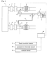
- a urea water supply system (hereinafter may simply be referred to as "system") and an exhaust emission control device of an internal combustion engine which the system is applied to, with reference to Figs. 1 and 2 .
- An internal combustion engine 1 shown in Fig. 1 is a diesel engine for driving a vehicle.
- the internal combustion engine of the invention is, however, not limited to the diesel engine but may be a gasoline engine or the like.
- the urea water supply system of the invention is configured to supply urea water to supply valves that are arranged to supply ammonium as a reducing agent to two NOx catalysts provided in an exhaust passage of the internal combustion engine 1.
- Exhaust emission control devices of Figs. 1 and 2 are illustrated as examples of the exhaust emission control device of the internal combustion engine which the system is applied to and are not at all intended to limit the application of the invention to both or either of the exhaust emission control devices.
- the following describes a first configuration of the urea water supply system of the invention and the exhaust emission control device of the internal combustion engine 1 which the urea water supply system is applied to, with reference to Fig. 1 .
- the internal combustion engine 1 is a V engine and has two connected exhaust passages 2 and 12 corresponding to respective banks of the V engine.
- the respective exhaust passages 2 and 12 basically have similar schematic configurations.
- a first NOx catalyst 5 is placed in the exhaust passage 2 to selectively reduce NOx in exhaust emission using ammonia as the reducing agent.
- urea water as a precursor of ammonia is stored in a urea water tank 9 and is supplied to the exhaust emission by means of a first supply valve 6 that is located in the upstream of the first NOx catalyst 5.
- the urea water supplied by the first supply valve 6 is hydrolyzed with heat of exhaust emission to produce ammonia.
- the ammonia then flows into and is adsorbed to the first NOx catalyst 5, so that NOx in the exhaust emission is removed through reduction reaction of ammonia with NOx.
- An oxidation catalyst for oxidizing ammonia slipped from the first NOx catalyst 5 (hereinafter referred to as "ASC catalyst") is provided in the downstream of the first NOx catalyst 5, although not being illustrated in Fig. 1 .
- an oxidation catalyst 3 having oxidation function and a filter 4 for trapping particulate substances in the exhaust emission are provided in the upstream of the first NOx catalyst 5 and the first supply valve 6.
- the oxidation catalyst 3 serves to oxidize a fuel component included in the exhaust emission, raise the temperature of the exhaust emission and flows out the heated exhaust emission to the filter 4, so that the particulate substances trapped by the filter 4 are oxidized and removed.
- the temperature rise of the exhaust emission by the oxidation catalyst 3 is achieved by adequately controlling the combustion conditions in the internal combustion engine 1 to regulate the fuel component (uncombusted component) in the exhaust emission and accelerate oxidation of the fuel component by the oxidation catalyst 3.
- a fuel supply valve may be provided in the upstream of the oxidation catalyst 3 to supply the fuel of the internal combustion engine 1 to the oxidation catalyst 3 via the exhaust emission.
- a second NOx catalyst 15 and a second supply valve 16 for supply urea water corresponding to the NOx catalyst are also provided in the exhaust passage 12 provided in parallel to the exhaust passage 2. Additionally, an oxidation catalyst 13 having oxidation function and a filter 14 for trapping particulate substances in the exhaust emission are provided in the upstream of the second NOx catalyst 15 and the second supply valve 16.
- the following describes a configuration of supplying urea water from the urea water tank 9 to the first supply valve 6 and the second supply valve 16.
- the urea water tank 9 is connected with the first supply valve 6 by a supply path L1 (supply path division from a point P1 on the urea water tank 9-side to a branch point P2) and a supply path L2 (supply path division from the branch point P2 to a first supply valve P3) that are arranged to supply the urea water.
- the urea water tank 9 is, on the other hand, connected with the second supply valve 16 by the supply path L1 and a supply path L3 (supply path division from the branch point P2 to a second supply valve P4) that are arranged to supply the rear water.
- the supply path L1 is shared by the supply paths formed between the urea water tank 9 and the first supply valve 6 and between the urea water tank 9 and the second supply valve 16, and only the flow of urea water to be supplied to each of the supply valves is pressure-fed through the supply path from the branch point P2 to each supply valve.
- a pump 7 for pressure-feeding the urea water in the supply paths L1 to L3 is provided in the common supply path L1. Normal rotation of the pump 7 causes the urea water to be pressure fed from the urea water tank 9 to each supply valve, and reverse rotation of the pump 7 causes the urea water to be pressure fed from each supply valve to the urea water tank 9.
- the exhaust passages 2 and 12, the urea water tank and the supply paths of urea water are placed along the vehicle body frame.
- the urea water tank 9 is placed at the position nearer to the exhaust passage 2.
- the overall length of the supply path L2 for the flow of urea water including the first supply valve 6 is thus shorter than the overall length of the supply path L3 for the flow of urea water including the second supply valve 16 (i.e., L2 ⁇ L3).
- the supply paths L1, L2 and L3 have an identical sectional area. The different lengths of the supply paths L2 and L3 accordingly causes the capacity of the supply path L3 to be greater than the capacity of the supply path L2 by a specified volume ⁇ V.
- a pressure sensor 8 is mounted to the pump 8 to detect the internal pressure of the supply path L1 for the urea water.
- the internal combustion engine 1 is provided with an electronic control unit (ECU) 20 that controls the operating conditions of the internal combustion engine 1 and the exhaust emission control device.
- the ECU 20 is electrically connected with a crank positions sensor 21 and an accelerator position sensor 22 in addition to the above pressure sensor 8 to receive detection values sent from the respective sensors.
- the ECU 20 accordingly obtains the operating conditions of the internal combustion engine 1, such as the detected internal pressure of the supply path L1, the engine rotation speed based on the detection of the crank position sensor 21 and the engine load based on the detection of the accelerator position sensor 22.
- the internal pressure of the supply path L1 may alternatively be estimated from, for example, the relationship between the driving power and the rotation speed of the pump 7.
- the pressure of urea water may be estimated by using the relationship between the driving power and the rotation speed.
- This modified configuration allows for omission of the pressure sensor 8.
- the ECU 20 is electrically connected with an ignition switch 23 to receive an ignition ON/OFF signal of the internal combustion engine 1.
- the pump 7, the first supply valve 6 and the second supply valve 16 are also electrically connected with the ECU 20 and are driven in response to control signals from the ECU 20.
- the following describes a second configuration of the urea water supply system of the invention and the exhaust emission control device of the internal combustion engine 1 which the urea water supply system is applied to, with reference to Fig. 2 .
- the like components of the urea supply system and the exhaust emission control device of the second configuration that are substantially similar to the components of the first configuration are expressed by the like signs and are not specifically described here.
- the internal combustion engine 1 of this configuration has one exhaust passage 2. Two NOx catalysts are arranged in series in the exhaust passage 2. More specifically, a first NOx catalyst 5 is arranged in the upstream along the flow of the exhaust emission, and a second NOx catalyst 15 is arranged in the downstream. In order to produce ammonia that works as the reducing agent in the first NOx catalyst 5, urea water stored in a urea water tank 9 is supplied to the exhaust emission by means of a first supply valve 6 that is located in the upstream of the first NOx catalyst 5.
- the urea water stored in the urea water tank 9 is supplied to the exhaust emission by means of a second supply valve 16 that is located in the upstream of the second NOx catalyst 15 but in the downstream of the first NOx catalyst 5.
- An oxidation catalyst 3 having oxidation function and a filter 4 for trapping particulate substances in the exhaust emission are provided in the upstream of the first NOx catalyst 5 and the first supply valve 6.
- the urea water tank 9 is connected with the first supply valve 6 by a supply path L1 (supply path division from a point P1 on the urea water tank 9-side to a branch point P2) and a supply path L2 (supply path division from the branch point P2 to a first supply valve P3) that are arranged to supply the urea water.
- a supply path L1 supply path division from a point P1 on the urea water tank 9-side to a branch point P2
- a supply path L2 supply path division from the branch point P2 to a first supply valve P3
- the urea water tank 9 is, on the other hand, connected with the second supply valve 16 by the supply path L1 and a supply path L3 (supply path division from the branch point P2 to a second supply valve P4) that are arranged to supply the rear water. Accordingly, the supply path L1 is shared by the supply paths formed between the urea water tank 9 and the first supply valve 6 and between the urea water tank 9 and the second supply valve 16, and only the flow of urea water to be supplied to each of the supply valves is pressure-fed through the supply path from the branch point P2 to each supply valve.
- the urea water tank 9 is placed at the position nearer to the first supply valve 6 than the second supply valve 16.
- the overall length of the supply path L2 for the flow of urea water including the first supply valve 6 is thus shorter than the overall length of the supply path L3 for the flow of urea water including the second supply valve 16.
- the urea water is pressure-fed from the urea water tank 9 to each supply valve and is supplied to the exhaust emission, in order to reduce NOx included in the discharged exhaust emission during operation of the internal combustion engine 1.
- ammonia is likely to be produced from the remaining urea water due to, for example, external heat and cause corrosion of the supply valve or the supply path.
- the urea water supply system of the invention performs control with regard to supply of urea water, in order to prevent the urea water from remaining in any of the supply valves and the supply paths when there is no requirement for using the urea water in the exhaust emission control device of the internal combustion engine 1.
- the urea water supply system of the invention performs suck-back control to return the urea water remaining in any of the supply valves and the supply paths to the urea water tank 9 at a stop of the internal combustion engine 1 and filling control to fill urea water into the vacant supply valves and supply paths to allow for supply of urea water to the exhaust emission at a start of the internal combustion engine 1, as the control with regard to supply of urea water.
- the following describes the details of filling control to fill urea water into the first supply valve 6, the second supply valve 16 and the relevant supply paths, in which no urea water substantially remains by the previous suck-back control.
- Fig. 3 is a flowchart of filling control performed by the ECU 20.
- the filling control is repeatedly performed at predetermined time intervals by the ECU 20 during operation of the internal combustion engine 1.
- the ECU 20 executes a predetermined control program to perform the control shown in the flowchart of Fig. 3 .
- the flow determines whether the current state is the state that is ready for supply of urea water from the urea water tank 9 to the respective supply valves 6 and 16. More specifically, when the internal combustion engine 1 is started and warm-up of both the NOx catalysts is completed, a filling ready flag for the filling control is changed from OFF to ON. An affirmative answer is given at S101 in response to the ON setting of the filling ready flag, and a negative answer is given at S101 in response to the OFF setting of the filling ready flag. In response to the affirmative answer at S101, the flow proceeds to S102. In response to the negative answer at S101, the flow terminates this control. Prior to a start of the internal combustion engine 1, no urea water substantially remains in the respective supply valves and the respective supply paths as described above.
- the flow normally rotates the pump 7. This applies a pressure to feed urea water from the urea water tank 9 to the supply paths L1 to L3 and the respective supply valves 6 and 16.
- the normally rotating state of the pump 7 corresponds to the specified operating state for filling of the claims.
- the flow starts open-close control of the respective supply valves 6 and 16, while the pump 7 is maintained in the normally rotating state. The details of open-close control will be described later.
- the flow proceeds to S104.
- the flow determines whether filling of urea water into the first supply valve 6 is completed. More specifically, the determination process of S104 determines an estimated time when filling of urea water into the first supply valve 6 is expected to be completed, based on a variation in internal pressure of the supply path L1 as described later. In response to an affirmative answer at S104, the flow proceeds to S105. In response to a negative answer at S104, the flow repeats the processing of S104. At S105, the flow closes the first supply valve 6.
- the flow proceeds to S106 to determine whether filling of urea water into the second supply valve 16 is completed. More specifically, the determination process of S106 determines an estimated time when filling of urea water into the second supply valve 16 is expected to be completed, based on a variation in internal pressure of the supply path L1 as described later. In response to an affirmative answer at S106, the flow closes the second supply valve 16 at S107 and then terminates this control. In response to a negative answer at S106, the flow repeats the processing of S106.
- Figs. 4 and 5 are time charts showing (a) variation in setting of the filling ready flag, (b) variation in pump rotation signal, (c) variation in open-close signal of the first supply valve 6, (d) variation in open-close signal of the second supply valve 16, (e) variation in amount of urea water in the supply path L2, (f) variation in amount of urea water in the supply path L3 and (g) variation in internal pressure of the supply path L1 with respect to the open-close control of the respective supply valves in various different filling patterns.
- the internal pressure of the supply path L1 denotes the pressure detected by the pressure sensor 8.
- the following describes the open-close control of the respective supply valves in the respective patterns of Figs. 4 and 5 .
- the following describes a first pattern of the open-close control of the respective supply valves for filling with reference to Fig. 4 .
- the filling ready flag is set ON at a time t11 as shown in Fig. 4(a)
- the pump 7 is normally rotated at the time t11 as shown in Fig. 4(b) (processing of S102).
- the pump 7 has the constant rotation speed and maintains the substantially constant pressure-feed capacity as described above.
- the first pattern as shown in Figs. 4(c) and 4(d) , the first supply valve 6 and the second supply valve 16 are simultaneously opened at a time t12, so that filling of urea water from the urea water tank 9 into the respective supply valves 6 and 16 is started.
- Figs. 4(e) and 4(f) show variations in amount of urea water in the supply paths L2 and L3 by such valve open-close control.
- urea water is first filled into the supply path L1 and is subsequently filled into the supply paths L2 and L3 and the respective supply valves 6 and 16.
- a time Tov1 after the time t17 corresponds to the valve-opening time of the first supply valve 6 to fill the supply path L2
- a time Tov2 after the time t17 corresponds to the valve-opening time of the second supply valve 16 to fill the supply path L3.
- the time period from the time t12 to the time t17 may be given as V2/ ⁇ , where V2 represents the capacity of the supply path L1 and ⁇ represents the pressure-feed capacity of the pump 7.
- completion of filling of urea water into each of the supply valves is determined, based on a variation in internal pressure of the supply path L1.
- simultaneously opening both the supply valves 6 and 16 at the time t12 fills urea water into the supply paths L2 and L3.
- the capacity of the supply path L2 is smaller than the capacity of the supply path L3 by a predetermined volume ⁇ V, so that filling of urea water into the supply path L2 and the first supply valve 6 is expected to be completed at an earlier timing than filling of urea water into the supply path L3 and the second supply valve 16.
- the resistance with regard to migration of urea water on the first supply valve 6-side increases to increase the pressure applied to the urea water in the course of filling.
- completion of filling of urea water into the first supply valve 6 is detected at the time when a time rate of change (rise rate) in internal pressure of the supply path L1 is significantly increased from the previous time rate of change of the pressure as shown in Fig. 4(g) . Based on this detection result, the first supply valve 6 is closed at a time t13 slightly delayed from the time t15 (processing of S105).
- the valve-closing time t13 is slightly delayed from the filling completion time t15, since a certain delay time is required between completion of filling of urea water into the supply path L2 and the first supply valve 6 and reflection of the completion of filling on the pressure of urea water to be detectable by the pressure sensor 8.
- urea water from the urea water tank 9 is only filled into the second supply valve 16.
- a time rate of change (rise rate) in internal pressure of the supply path L1 is significantly increased from the previous time rate of change of the pressure in the time period from the time t15 to the time t16 as shown in Fig. 4(g) .
- filling of urea water into the second supply valve 16 is detected.
- the second supply valve 16 is closed at a time t14 slightly delayed from the time t16 (processing of S107).
- the valve-closing time t14 is slightly delayed from the filling completion time t16, because of the same reason as that described above with regard to the first supply valve 6.
- Such open-close control of the respective supply valves 6 and 16 enables just enough amounts of urea water to be filled into the first supply valve 6 and the second supply valve 16.
- a difference between the valve-opening time Tov1 of the first supply valve 6 and the valve-opening time Tov2 of the second supply valve 16 for filling urea water reflects the predetermined volume ⁇ V that is the difference between the capacities of the supply paths L2 and L3. Accordingly, the valve-opening time Tov1 of the first supply valve 6 is shorter than the valve-opening time Tov2 of the second supply valve 16 by a time required for filling urea water into the predetermined volume ⁇ V of the supply path L3.
- the valve-closing timings of the first supply valve 6 and the second supply valve 16 are determined based on the pressure value detected by the pressure sensor 8 and its time rate of change, so as to ensure efficient filling of urea water.
- the following describes a second pattern of the open-close control of the respective supply valves for filling with reference to Fig.5 .
- the filling ready flag is set ON at a time t11 as shown in Fig. 5(a)
- the pump 7 is normally rotated at the time t11 as shown in Fig. 5(b) (processing of S102).
- the pump 7 has the constant rotation speed and maintains the substantially constant pressure-feed capacity as described above.
- the open-close control of the respective supply valves is started at a time t12.
- the second pattern as shown in Figs. 5(c) and 5(d) , at the time t12, only the first supply valve 6 is opened, so that filling of urea water into the first supply valve 6 is performed.
- Figs. 5(e) and 5(f) show variations in amount of urea water in the supply paths L2 and L3 by such valve open-close control.
- urea water is first filled into the supply path L1 and is subsequently filled into the supply path L2 and the first supply valve 6.
- a time Tov1 after the time t17 corresponds to the valve-opening time of the first supply valve 6 to fill the supply path L2
- a time Tov2 after closing the first supply valve 6 corresponds to the valve-opening time of the second supply valve 16 to fill the supply path L3.
- the time period from the time t12 to the time t17 may be given as V2/ ⁇ .
- completion of filling of urea water into each of the supply valves is also determined, based on a variation in internal pressure of the supply path L1.
- opening only the first supply valve 6 at the time t12 causes urea water to be filled into the supply path L2 after the time t17.
- the second supply valve 16 is still kept closed, so that the internal pressure of the supply path L1 abruptly increases. Completion of filling of urea water into the first supply valve 6 is detected at the time of the abrupt pressure increase.
- the first supply valve 6 is closed at a time t13 slightly delayed from the time t15.
- the valve-closing time t13 is slightly delayed from the filling completion time t15, since a certain delay time is required to make the pressure increase detectable by the pressure sensor 8.
- the first supply valve 6 is closed on completion of filling (processing of S105) and the second supply valve 16 is opened at the same time. This suppresses the increase in internal pressure of the supply path L1. Subsequently urea water is filled through the supply path L3 into the second supply valve 16.
- a time rate of change (rise rate) in internal pressure of the supply path L1 is significantly increased from the previous time rate of change of the pressure in the time period from the time t15 to the time t16 as shown in Fig. 5(g) .
- the second supply valve 16 is closed at a time t14 slightly delayed from the time t16 (processing of S107).
- the valve-closing time t14 is slightly delayed from the filling completion time t16, because of the same reason as that described above with regard to the first supply valve 6.
- Such open-close control of the respective supply valves 6 and 16 enables just enough amounts of urea water to be filled into the first supply valve 6 and the second supply valve 16.
- a difference between the valve-opening time Tov1 of the first supply valve 6 and the valve-opening time Tov2 of the second supply valve 16 for filling urea water reflects the predetermined volume ⁇ V that is the difference between the capacities of the supply paths L2 and L3. Accordingly, the valve-opening time Tov1 of the first supply valve 6 is shorter than the valve-opening time Tov2 of the second supply valve 16 by a time required for filling urea water into the predetermined volume ⁇ V of the supply path L3.
- the valve-closing timings of the first supply valve 6 and the second supply valve 16 are determined based on the pressure value detected by the pressure sensor 8 and its time rate of change, so as to ensure efficient filling of urea water.
- Fig. 7 shows a time chart showing (a) variation in setting of the filling ready flag, (b) variation in pump rotation signal, (c) variation in open-close signal of the first supply valve 6, (d) variation in open-close signal of the second supply valve 16, (e) variation in amount of urea water in the supply path L2, (f) variation in amount of urea water in the supply path L3 and (g) variation in internal pressure of the supply path L1 with respect to the open-close control of the respective supply valves in the filling control shown in Fig. 6 .
- the flow performs a clogging detection process with regard to clogging in the first supply valve 6 at S201.
- completion of filling of urea water into each of the supply valves is determined, based on a variation in internal pressure of the supply path L1. More specifically, at a time t20 when the internal pressure of the supply path L1 has an increase after the first supply valve 6 and the second supply valve 16 are opened, the flow determines that filling of urea water into the first supply valve 6 is completed (affirmative answer is given at S104) and closes the first supply valve 6 (processing of S105). As a result, only the second supply valve 16 is kept open.
- the predetermined time T0 is preferably set to be as short as possible in such a range that allows for detection of clogging of the first supply valve 6, in order to suppress urea water from leaking from the second supply valve 16 that has already been filled with urea water.
- the flow closes the second supply valve 16 in order to suppress urea water from leaking from the second supply valve 16 that has already been filled with urea water, while additionally opening the first supply valve 6 (processing of S202) in order to additionally fill urea water into the first supply valve 6 in the insufficient filling state.
- completion of filling into the first supply valve 6 may be determined, based on a variation in internal pressure of the supply path L1 at a time t22 when urea water is actually filled into the supply path L2 and reaches the first supply valve 6 (processing of S203).
- the flow then closes the first supply valve 6 (processing of S204) at a time t23 slightly delayed from the time t22 when an affirmative answer is given at S203. If the flow determines that the first supply valve 6 is not clogged at S201 (negative answer is given at S201), the flow proceeds to S106 and S107.
- Such open-close control of the respective supply valves 6 and 16 enables urea water to be efficiently filled into the respective supply valves 6 and 16 even when the first supply valve 6 is clogged.
Applications Claiming Priority (3)
| Application Number | Priority Date | Filing Date | Title |
|---|---|---|---|
| JP2014121579 | 2014-06-12 | ||
| JP2015105675 | 2015-05-25 | ||
| JP2015114340A JP6222168B2 (ja) | 2014-06-12 | 2015-06-04 | 尿素水供給システム |
Publications (2)
| Publication Number | Publication Date |
|---|---|
| EP2955351A1 true EP2955351A1 (de) | 2015-12-16 |
| EP2955351B1 EP2955351B1 (de) | 2017-07-26 |
Family
ID=53433033
Family Applications (1)
| Application Number | Title | Priority Date | Filing Date |
|---|---|---|---|
| EP15171691.7A Active EP2955351B1 (de) | 2014-06-12 | 2015-06-11 | Befüllen eines harnstoff-fördersystems |
Country Status (2)
| Country | Link |
|---|---|
| US (1) | US9551261B2 (de) |
| EP (1) | EP2955351B1 (de) |
Cited By (2)
| Publication number | Priority date | Publication date | Assignee | Title |
|---|---|---|---|---|
| WO2019025870A1 (en) * | 2017-08-02 | 2019-02-07 | Robert Bosch Gmbh | FED INJECTION STRATEGY FOR MULTIPLE INJECTION SYSTEMS |
| US11098625B2 (en) | 2017-08-02 | 2021-08-24 | Robert Bosch Gmbh | Multiple def injection concept for reducing risk of solid deposits formation in diesel aftertreatment systems |
Families Citing this family (5)
| Publication number | Priority date | Publication date | Assignee | Title |
|---|---|---|---|---|
| SE539129C2 (en) | 2015-08-27 | 2017-04-11 | Scania Cv Ab | Process and system for processing a single stream combustion exhaust stream |
| SE539133C2 (sv) * | 2015-08-27 | 2017-04-11 | Scania Cv Ab | Avgasbehandlingssystem och förfarande för behandling av en avgasström |
| EP4234901A3 (de) * | 2016-02-24 | 2024-02-28 | Jtsmcdp, Llc | Systeme, vorrichtungen und verfahren zur regeneration eines partikelfilters |
| JP7447839B2 (ja) * | 2021-02-08 | 2024-03-12 | 株式会社デンソー | 尿素水供給システム |
| CN114215629B (zh) * | 2021-12-02 | 2023-01-31 | 江铃汽车股份有限公司 | 一种电控式尿素喷射系统的排空方法 |
Citations (5)
| Publication number | Priority date | Publication date | Assignee | Title |
|---|---|---|---|---|
| US20040118109A1 (en) * | 2002-12-19 | 2004-06-24 | Gladden John R. | Enhanced ammonia feed control for selective catalytic reduction |
| JP2010007617A (ja) | 2008-06-30 | 2010-01-14 | Denso Corp | 還元剤供給システム |
| EP2660436A1 (de) * | 2012-05-03 | 2013-11-06 | Emitec France S.A.S. | Verfahren zum Entlüften einer Fördereinheit für ein flüssiges Additiv |
| JP2014001835A (ja) | 2012-06-20 | 2014-01-09 | Nissei Corp | ピニオン付きシャフト及び減速機 |
| WO2014041899A1 (ja) * | 2012-09-13 | 2014-03-20 | 株式会社小松製作所 | 排ガス処理装置、ディーゼルエンジン及び排ガス処理方法 |
Family Cites Families (12)
| Publication number | Priority date | Publication date | Assignee | Title |
|---|---|---|---|---|
| JP3246086B2 (ja) | 1993-06-11 | 2002-01-15 | トヨタ自動車株式会社 | 内燃機関の排気浄化装置 |
| US6471924B1 (en) | 1995-07-12 | 2002-10-29 | Engelhard Corporation | Method and apparatus for NOx abatement in lean gaseous streams |
| US6125629A (en) * | 1998-11-13 | 2000-10-03 | Engelhard Corporation | Staged reductant injection for improved NOx reduction |
| US6182444B1 (en) | 1999-06-07 | 2001-02-06 | Ford Global Technologies, Inc. | Emission control system |
| US6293097B1 (en) | 1999-08-16 | 2001-09-25 | Ford Global Technologies, Inc. | On-board reductant delivery system |
| US6269633B1 (en) | 2000-03-08 | 2001-08-07 | Ford Global Technologies, Inc. | Emission control system |
| US7021048B2 (en) * | 2002-01-25 | 2006-04-04 | Arvin Technologies, Inc. | Combination emission abatement assembly and method of operating the same |
| CN101292077B (zh) * | 2005-10-18 | 2010-06-23 | 丰田自动车株式会社 | 内燃机的排气净化装置 |
| GB2460825A (en) * | 2008-06-06 | 2009-12-16 | Delphi Tech Inc | Reagent dosing system |
| US8635855B2 (en) * | 2009-06-17 | 2014-01-28 | GM Global Technology Operations LLC | Exhaust gas treatment system including a lean NOx trap and two-way catalyst and method of using the same |
| US8997461B2 (en) * | 2012-05-21 | 2015-04-07 | Cummins Emission Solutions Inc. | Aftertreatment system having two SCR catalysts |
| US9150139B2 (en) | 2012-06-29 | 2015-10-06 | Caterpillar Inc. | Reductant refill and purging system |
-
2015
- 2015-06-11 EP EP15171691.7A patent/EP2955351B1/de active Active
- 2015-06-12 US US14/737,602 patent/US9551261B2/en active Active
Patent Citations (5)
| Publication number | Priority date | Publication date | Assignee | Title |
|---|---|---|---|---|
| US20040118109A1 (en) * | 2002-12-19 | 2004-06-24 | Gladden John R. | Enhanced ammonia feed control for selective catalytic reduction |
| JP2010007617A (ja) | 2008-06-30 | 2010-01-14 | Denso Corp | 還元剤供給システム |
| EP2660436A1 (de) * | 2012-05-03 | 2013-11-06 | Emitec France S.A.S. | Verfahren zum Entlüften einer Fördereinheit für ein flüssiges Additiv |
| JP2014001835A (ja) | 2012-06-20 | 2014-01-09 | Nissei Corp | ピニオン付きシャフト及び減速機 |
| WO2014041899A1 (ja) * | 2012-09-13 | 2014-03-20 | 株式会社小松製作所 | 排ガス処理装置、ディーゼルエンジン及び排ガス処理方法 |
Cited By (3)
| Publication number | Priority date | Publication date | Assignee | Title |
|---|---|---|---|---|
| WO2019025870A1 (en) * | 2017-08-02 | 2019-02-07 | Robert Bosch Gmbh | FED INJECTION STRATEGY FOR MULTIPLE INJECTION SYSTEMS |
| US10954840B2 (en) | 2017-08-02 | 2021-03-23 | Robert Bosch Gmbh | Def injection strategy for multiple injection systems |
| US11098625B2 (en) | 2017-08-02 | 2021-08-24 | Robert Bosch Gmbh | Multiple def injection concept for reducing risk of solid deposits formation in diesel aftertreatment systems |
Also Published As
| Publication number | Publication date |
|---|---|
| US9551261B2 (en) | 2017-01-24 |
| US20150361858A1 (en) | 2015-12-17 |
| EP2955351B1 (de) | 2017-07-26 |
Similar Documents
| Publication | Publication Date | Title |
|---|---|---|
| US9512769B2 (en) | Urea water supply system | |
| US9551261B2 (en) | Urea water supply system | |
| US9181834B2 (en) | Method and device for adapting the injection agent supply in an injection system, and exhaust gas aftertreatment system | |
| EP1900928A1 (de) | Abgasreinigungssystem für einen verbrennungsmotor | |
| US10337386B2 (en) | Method of testing a proper functioning of a selective catalytic reduction system | |
| US20160356193A1 (en) | Method For Checking A Temperature Sensor In An SCR Exhaust Gas Post-Treatment System | |
| FR2926847A1 (fr) | Procede de diagnostic d'un dispositif de traitement des gaz d'echappement et dispositif pour la mise en oeuvre du procede. | |
| CN106246378B (zh) | 用于操作内燃发动机的方法 | |
| US8540953B2 (en) | Exhaust gas control apparatus and reductant dispensing method for internal combustion engine | |
| JP6222168B2 (ja) | 尿素水供給システム | |
| EP2573344A1 (de) | Gültigkeitsdiagnosesystem für einen harnstofftemperatursensor | |
| EP3025036B1 (de) | Scr-abgasemissionssteuerungssystem und verfahren dafür zum auffüllen des harnstoff-reduktionsmittels nach rückführung in den tank | |
| EP1662123B1 (de) | Vorrichtung zur Erhöhung der Temperatur eines Katalysators für Brennkraftmaschine | |
| JP6409700B2 (ja) | 燃料用フィルタ装置 | |
| US8943814B2 (en) | Warm-up system for exhaust system of internal combustion engine | |
| EP2905443B1 (de) | Abgasreinigungsvorrichtung für einen verbrennungsmotor | |
| US10344645B2 (en) | Exhaust gas purification apparatus for internal combustion engine | |
| US9567891B2 (en) | Method for controlling an oxygen concentration | |
| JP7013820B2 (ja) | 還元剤添加システム | |
| JP2018135776A (ja) | 排気処理装置 | |
| GB2585911A (en) | A liquid injection system for a vehicle | |
| JP7447839B2 (ja) | 尿素水供給システム | |
| JP6354558B2 (ja) | 燃料噴射システムの制御装置 | |
| JP6459463B2 (ja) | 燃料噴射システムの制御装置 | |
| JP2017089445A (ja) | 内燃機関の制御装置 |
Legal Events
| Date | Code | Title | Description |
|---|---|---|---|
| PUAI | Public reference made under article 153(3) epc to a published international application that has entered the european phase |
Free format text: ORIGINAL CODE: 0009012 |
|
| 17P | Request for examination filed |
Effective date: 20150611 |
|
| AK | Designated contracting states |
Kind code of ref document: A1 Designated state(s): AL AT BE BG CH CY CZ DE DK EE ES FI FR GB GR HR HU IE IS IT LI LT LU LV MC MK MT NL NO PL PT RO RS SE SI SK SM TR |
|
| AX | Request for extension of the european patent |
Extension state: BA ME |
|
| GRAP | Despatch of communication of intention to grant a patent |
Free format text: ORIGINAL CODE: EPIDOSNIGR1 |
|
| STAA | Information on the status of an ep patent application or granted ep patent |
Free format text: STATUS: GRANT OF PATENT IS INTENDED |
|
| INTG | Intention to grant announced |
Effective date: 20170109 |
|
| GRAS | Grant fee paid |
Free format text: ORIGINAL CODE: EPIDOSNIGR3 |
|
| GRAA | (expected) grant |
Free format text: ORIGINAL CODE: 0009210 |
|
| STAA | Information on the status of an ep patent application or granted ep patent |
Free format text: STATUS: THE PATENT HAS BEEN GRANTED |
|
| AK | Designated contracting states |
Kind code of ref document: B1 Designated state(s): AL AT BE BG CH CY CZ DE DK EE ES FI FR GB GR HR HU IE IS IT LI LT LU LV MC MK MT NL NO PL PT RO RS SE SI SK SM TR |
|
| REG | Reference to a national code |
Ref country code: GB Ref legal event code: FG4D |
|
| REG | Reference to a national code |
Ref country code: CH Ref legal event code: EP |
|
| REG | Reference to a national code |
Ref country code: AT Ref legal event code: REF Ref document number: 912602 Country of ref document: AT Kind code of ref document: T Effective date: 20170815 |
|
| REG | Reference to a national code |
Ref country code: IE Ref legal event code: FG4D |
|
| REG | Reference to a national code |
Ref country code: DE Ref legal event code: R096 Ref document number: 602015003720 Country of ref document: DE |
|
| REG | Reference to a national code |
Ref country code: NL Ref legal event code: MP Effective date: 20170726 |
|
| REG | Reference to a national code |
Ref country code: LT Ref legal event code: MG4D |
|
| REG | Reference to a national code |
Ref country code: AT Ref legal event code: MK05 Ref document number: 912602 Country of ref document: AT Kind code of ref document: T Effective date: 20170726 |
|
| PG25 | Lapsed in a contracting state [announced via postgrant information from national office to epo] |
Ref country code: FI Free format text: LAPSE BECAUSE OF FAILURE TO SUBMIT A TRANSLATION OF THE DESCRIPTION OR TO PAY THE FEE WITHIN THE PRESCRIBED TIME-LIMIT Effective date: 20170726 Ref country code: NL Free format text: LAPSE BECAUSE OF FAILURE TO SUBMIT A TRANSLATION OF THE DESCRIPTION OR TO PAY THE FEE WITHIN THE PRESCRIBED TIME-LIMIT Effective date: 20170726 Ref country code: HR Free format text: LAPSE BECAUSE OF FAILURE TO SUBMIT A TRANSLATION OF THE DESCRIPTION OR TO PAY THE FEE WITHIN THE PRESCRIBED TIME-LIMIT Effective date: 20170726 Ref country code: LT Free format text: LAPSE BECAUSE OF FAILURE TO SUBMIT A TRANSLATION OF THE DESCRIPTION OR TO PAY THE FEE WITHIN THE PRESCRIBED TIME-LIMIT Effective date: 20170726 Ref country code: AT Free format text: LAPSE BECAUSE OF FAILURE TO SUBMIT A TRANSLATION OF THE DESCRIPTION OR TO PAY THE FEE WITHIN THE PRESCRIBED TIME-LIMIT Effective date: 20170726 Ref country code: NO Free format text: LAPSE BECAUSE OF FAILURE TO SUBMIT A TRANSLATION OF THE DESCRIPTION OR TO PAY THE FEE WITHIN THE PRESCRIBED TIME-LIMIT Effective date: 20171026 Ref country code: SE Free format text: LAPSE BECAUSE OF FAILURE TO SUBMIT A TRANSLATION OF THE DESCRIPTION OR TO PAY THE FEE WITHIN THE PRESCRIBED TIME-LIMIT Effective date: 20170726 |
|
| PG25 | Lapsed in a contracting state [announced via postgrant information from national office to epo] |
Ref country code: GR Free format text: LAPSE BECAUSE OF FAILURE TO SUBMIT A TRANSLATION OF THE DESCRIPTION OR TO PAY THE FEE WITHIN THE PRESCRIBED TIME-LIMIT Effective date: 20171027 Ref country code: PL Free format text: LAPSE BECAUSE OF FAILURE TO SUBMIT A TRANSLATION OF THE DESCRIPTION OR TO PAY THE FEE WITHIN THE PRESCRIBED TIME-LIMIT Effective date: 20170726 Ref country code: IS Free format text: LAPSE BECAUSE OF FAILURE TO SUBMIT A TRANSLATION OF THE DESCRIPTION OR TO PAY THE FEE WITHIN THE PRESCRIBED TIME-LIMIT Effective date: 20171126 Ref country code: ES Free format text: LAPSE BECAUSE OF FAILURE TO SUBMIT A TRANSLATION OF THE DESCRIPTION OR TO PAY THE FEE WITHIN THE PRESCRIBED TIME-LIMIT Effective date: 20170726 Ref country code: RS Free format text: LAPSE BECAUSE OF FAILURE TO SUBMIT A TRANSLATION OF THE DESCRIPTION OR TO PAY THE FEE WITHIN THE PRESCRIBED TIME-LIMIT Effective date: 20170726 Ref country code: LV Free format text: LAPSE BECAUSE OF FAILURE TO SUBMIT A TRANSLATION OF THE DESCRIPTION OR TO PAY THE FEE WITHIN THE PRESCRIBED TIME-LIMIT Effective date: 20170726 Ref country code: BG Free format text: LAPSE BECAUSE OF FAILURE TO SUBMIT A TRANSLATION OF THE DESCRIPTION OR TO PAY THE FEE WITHIN THE PRESCRIBED TIME-LIMIT Effective date: 20171026 |
|
| REG | Reference to a national code |
Ref country code: DE Ref legal event code: R084 Ref document number: 602015003720 Country of ref document: DE |
|
| REG | Reference to a national code |
Ref country code: GB Ref legal event code: 746 Effective date: 20180320 |
|
| PG25 | Lapsed in a contracting state [announced via postgrant information from national office to epo] |
Ref country code: DK Free format text: LAPSE BECAUSE OF FAILURE TO SUBMIT A TRANSLATION OF THE DESCRIPTION OR TO PAY THE FEE WITHIN THE PRESCRIBED TIME-LIMIT Effective date: 20170726 Ref country code: CZ Free format text: LAPSE BECAUSE OF FAILURE TO SUBMIT A TRANSLATION OF THE DESCRIPTION OR TO PAY THE FEE WITHIN THE PRESCRIBED TIME-LIMIT Effective date: 20170726 Ref country code: RO Free format text: LAPSE BECAUSE OF FAILURE TO SUBMIT A TRANSLATION OF THE DESCRIPTION OR TO PAY THE FEE WITHIN THE PRESCRIBED TIME-LIMIT Effective date: 20170726 |
|
| REG | Reference to a national code |
Ref country code: DE Ref legal event code: R097 Ref document number: 602015003720 Country of ref document: DE |
|
| REG | Reference to a national code |
Ref country code: FR Ref legal event code: PLFP Year of fee payment: 4 |
|
| PG25 | Lapsed in a contracting state [announced via postgrant information from national office to epo] |
Ref country code: SK Free format text: LAPSE BECAUSE OF FAILURE TO SUBMIT A TRANSLATION OF THE DESCRIPTION OR TO PAY THE FEE WITHIN THE PRESCRIBED TIME-LIMIT Effective date: 20170726 Ref country code: SM Free format text: LAPSE BECAUSE OF FAILURE TO SUBMIT A TRANSLATION OF THE DESCRIPTION OR TO PAY THE FEE WITHIN THE PRESCRIBED TIME-LIMIT Effective date: 20170726 Ref country code: EE Free format text: LAPSE BECAUSE OF FAILURE TO SUBMIT A TRANSLATION OF THE DESCRIPTION OR TO PAY THE FEE WITHIN THE PRESCRIBED TIME-LIMIT Effective date: 20170726 Ref country code: IT Free format text: LAPSE BECAUSE OF FAILURE TO SUBMIT A TRANSLATION OF THE DESCRIPTION OR TO PAY THE FEE WITHIN THE PRESCRIBED TIME-LIMIT Effective date: 20170726 |
|
| PLBE | No opposition filed within time limit |
Free format text: ORIGINAL CODE: 0009261 |
|
| STAA | Information on the status of an ep patent application or granted ep patent |
Free format text: STATUS: NO OPPOSITION FILED WITHIN TIME LIMIT |
|
| 26N | No opposition filed |
Effective date: 20180430 |
|
| PG25 | Lapsed in a contracting state [announced via postgrant information from national office to epo] |
Ref country code: SI Free format text: LAPSE BECAUSE OF FAILURE TO SUBMIT A TRANSLATION OF THE DESCRIPTION OR TO PAY THE FEE WITHIN THE PRESCRIBED TIME-LIMIT Effective date: 20170726 |
|
| REG | Reference to a national code |
Ref country code: CH Ref legal event code: PL |
|
| REG | Reference to a national code |
Ref country code: BE Ref legal event code: MM Effective date: 20180630 |
|
| REG | Reference to a national code |
Ref country code: IE Ref legal event code: MM4A |
|
| PG25 | Lapsed in a contracting state [announced via postgrant information from national office to epo] |
Ref country code: MC Free format text: LAPSE BECAUSE OF FAILURE TO SUBMIT A TRANSLATION OF THE DESCRIPTION OR TO PAY THE FEE WITHIN THE PRESCRIBED TIME-LIMIT Effective date: 20170726 Ref country code: LU Free format text: LAPSE BECAUSE OF NON-PAYMENT OF DUE FEES Effective date: 20180611 |
|
| PG25 | Lapsed in a contracting state [announced via postgrant information from national office to epo] |
Ref country code: IE Free format text: LAPSE BECAUSE OF NON-PAYMENT OF DUE FEES Effective date: 20180611 Ref country code: CH Free format text: LAPSE BECAUSE OF NON-PAYMENT OF DUE FEES Effective date: 20180630 Ref country code: LI Free format text: LAPSE BECAUSE OF NON-PAYMENT OF DUE FEES Effective date: 20180630 |
|
| PG25 | Lapsed in a contracting state [announced via postgrant information from national office to epo] |
Ref country code: BE Free format text: LAPSE BECAUSE OF NON-PAYMENT OF DUE FEES Effective date: 20180630 |
|
| PG25 | Lapsed in a contracting state [announced via postgrant information from national office to epo] |
Ref country code: MT Free format text: LAPSE BECAUSE OF NON-PAYMENT OF DUE FEES Effective date: 20180611 |
|
| PG25 | Lapsed in a contracting state [announced via postgrant information from national office to epo] |
Ref country code: TR Free format text: LAPSE BECAUSE OF FAILURE TO SUBMIT A TRANSLATION OF THE DESCRIPTION OR TO PAY THE FEE WITHIN THE PRESCRIBED TIME-LIMIT Effective date: 20170726 |
|
| PG25 | Lapsed in a contracting state [announced via postgrant information from national office to epo] |
Ref country code: PT Free format text: LAPSE BECAUSE OF FAILURE TO SUBMIT A TRANSLATION OF THE DESCRIPTION OR TO PAY THE FEE WITHIN THE PRESCRIBED TIME-LIMIT Effective date: 20170726 |
|
| PG25 | Lapsed in a contracting state [announced via postgrant information from national office to epo] |
Ref country code: HU Free format text: LAPSE BECAUSE OF FAILURE TO SUBMIT A TRANSLATION OF THE DESCRIPTION OR TO PAY THE FEE WITHIN THE PRESCRIBED TIME-LIMIT; INVALID AB INITIO Effective date: 20150611 Ref country code: CY Free format text: LAPSE BECAUSE OF FAILURE TO SUBMIT A TRANSLATION OF THE DESCRIPTION OR TO PAY THE FEE WITHIN THE PRESCRIBED TIME-LIMIT Effective date: 20170726 Ref country code: MK Free format text: LAPSE BECAUSE OF NON-PAYMENT OF DUE FEES Effective date: 20170726 |
|
| PG25 | Lapsed in a contracting state [announced via postgrant information from national office to epo] |
Ref country code: AL Free format text: LAPSE BECAUSE OF FAILURE TO SUBMIT A TRANSLATION OF THE DESCRIPTION OR TO PAY THE FEE WITHIN THE PRESCRIBED TIME-LIMIT Effective date: 20170726 |
|
| REG | Reference to a national code |
Ref country code: DE Ref legal event code: R081 Ref document number: 602015003720 Country of ref document: DE Owner name: KABUSHIKI KAISHA TOYOTA JIDOSHOKKI, KARIYA-SHI, JP Free format text: FORMER OWNER: TOYOTA JIDOSHA KABUSHIKI KAISHA, TOYOTA-SHI, AICHI-KEN, JP |
|
| PGFP | Annual fee paid to national office [announced via postgrant information from national office to epo] |
Ref country code: GB Payment date: 20220428 Year of fee payment: 8 Ref country code: DE Payment date: 20220505 Year of fee payment: 8 |
|
| REG | Reference to a national code |
Ref country code: GB Ref legal event code: 732E Free format text: REGISTERED BETWEEN 20220908 AND 20220914 |
|
| PGFP | Annual fee paid to national office [announced via postgrant information from national office to epo] |
Ref country code: FR Payment date: 20230510 Year of fee payment: 9 |
|
| P01 | Opt-out of the competence of the unified patent court (upc) registered |
Effective date: 20231024 |
|
| REG | Reference to a national code |
Ref country code: DE Ref legal event code: R119 Ref document number: 602015003720 Country of ref document: DE |
|
| GBPC | Gb: european patent ceased through non-payment of renewal fee |
Effective date: 20230611 |
|
| PG25 | Lapsed in a contracting state [announced via postgrant information from national office to epo] |
Ref country code: DE Free format text: LAPSE BECAUSE OF NON-PAYMENT OF DUE FEES Effective date: 20240103 Ref country code: GB Free format text: LAPSE BECAUSE OF NON-PAYMENT OF DUE FEES Effective date: 20230611 |